UAV-1004233-001 Rev D
AV-30-E
Pilot’s Guide

UAV-1004233-001, AV-30-E Pilot’s Guide Rev D Page 2
© 2020 - 2021 uAvionix Corporation. All rights reserved.
uAvionix Corporation
Bigfork, MT
www.uavionix.com
Except as expressly provided herein, no part of this guide may be
reproduced, transmitted, disseminated, downloaded, or stored in any
storage medium, for any purpose without the express written permission of
uAvionix. uAvionix grants permissions to download a single copy of this
guide onto an electronic storage medium to be viewed for personal use,
provided that the complete text of this copyright notice is retained.
Unauthorized commercial distribution of this manual or any revision hereto
is strictly prohibited.
uAvionix® and Ping® are registered trademarks of uAvionix Corporation
and may not be used without express permission of uAvionix.
AV-30, AV-30-E, and AV-30-C, BeaconX, tailBeaconX, and skyBeaconX
are trademarks of uAvionix Corporation and may not be used without
express permission of uAvionix.
Patents uavionix.com/patents

UAV-1004233-001, AV-30-E Pilot’s Guide Rev D Page 3
1 Revision History
Revision Date Comments
A. 6/2/2020 Initial release.
B. 5/4/2021
Add AV-Link feature.
Add traffic display feature.
Add transponder control feature.
C 5/20/2021 Section 7.5.5 Correction of non-slaved DG
D 7/22/2021 Added features of tailBeaconX and software
update aiding features.

UAV-1004233-001, AV-30-E Pilot’s Guide Rev D Page 4
2 Warnings / Disclaimers
All device operational procedures must be learned on the ground.
uAvionix is not liable for damages arising from the use or misuse of this
product.
This equipment is classified by the United States Department of
Commerce's Bureau of Industry and Security (BIS) as Export Control
Classification Number (ECCN) 7A994.
These items are controlled by the U.S. Government and authorized for
export only to the country of ultimate destination for use by the ultimate
consignee or end-user(s) herein identified. They may not be resold,
transferred, or otherwise disposed of, to any other country or to any
person other than the authorized ultimate consignee or end-user(s), either
in their original form or after being incorporated into other items, without
first obtaining approval from the U.S. Government or as otherwise
authorized by U.S. law and regulations.

UAV-1004233-001, AV-30-E Pilot’s Guide Rev D Page 5
3 Limited Warranty
uAvionix products are warranted to be free from defects in material and
workmanship for two years from the installation of AV-30-E on the aircraft.
For the duration of the warranty period, uAvionix, at its sole option, will
repair or replace any product which fails in normal use. Such repairs or
replacement will be made at no charge to the customer for parts or labor,
provided that the customer shall be responsible for any transportation cost.
Restrictions: This warranty does not apply to cosmetic damage,
consumable parts, damage caused by accident, abuse, misuse, fire or
flood, theft, damage caused by unauthorized servicing, or product that has
been modified or altered.
Disclaimer of Warranty: IN NO EVENT, SHALL UAVIONIX BE LIABLE
FOR ANY INCIDENTAL, SPECIAL, INDIRECT OR CONSEQUENTIAL
DAMAGES, WHETHER RESULTING FROM THE USE, MISUSE, OR
INABILITY TO USE THE PRODUCT OR FROM DEFECTS IN THE
PRODUCT. SOME STATES DO NOT ALLOW THE EXCLUSION OF
INCIDENTAL OR CONSEQUENTIAL DAMAGES, SO THE ABOVE
LIMITATIONS MAY NOT APPLY TO YOU.
Warranty Service: Warranty repair service shall be provided directly by
uAvionix. Proof of purchase for the product from uAvionix or authorized
reseller is required to obtain and better expedite warranty service.
Please email or call uAvionix support with a description of the problem you
are experiencing. Also, please provide the model, serial number, shipping
address and a daytime contact number.
You will be promptly contacted with further troubleshooting steps or return
instructions. It is recommended to use a shipping method with tracking and
insurance.
UAV-1004233-001, AV-30-E Pilot’s Guide Rev D Page 6
4 Table of Contents
1 Revision History ................................................................................. 3
2 Warnings / Disclaimers ....................................................................... 4
3 Limited Warranty ................................................................................ 5
4 Table of Contents ............................................................................... 6
5 AV-30-E System Information ............................................................ 10
System Description .................................................................... 10
System Functions ...................................................................... 12
6 Unit Interfaces .................................................................................. 13
Aircraft Systems Interfaces ........................................................ 13
Power Input (Required) ............................................................. 14
Pitot and Static Interfaces (Required) ........................................ 15
GPS Interface (Optional) ........................................................... 15
OAT Probe (Optional) ................................................................ 15
Audio Output (Optional) ............................................................. 16
Transponder Control (Optional) ................................................. 16
AV-Link Interface (Optional) ...................................................... 16
Magnetometer Aiding (Optional) ................................................ 17
7 User Interface ................................................................................... 17
Startup and Common Controls .................................................. 17
Push-Set ................................................................................... 18
User Interface Customization .................................................... 20
7.3.1 AI Mode Customization ........................................................ 21
7.3.2 Edit Presented Data ............................................................. 22
AI Mode Display Components ................................................... 23
7.4.1 Basic Components ............................................................... 23
7.4.2 Customizable Data Overlay Fields ....................................... 23
7.4.3 Attitude / Slip ........................................................................ 24
7.4.4 Airspeed Indicator ................................................................ 25

UAV-1004233-001, AV-30-E Pilot’s Guide Rev D Page 7
7.4.5 Flight Direction Indicator ...................................................... 27
7.4.6 Barometric Corrected Altitude Indicator ................................ 27
7.4.7 AoA Indication ...................................................................... 29
7.4.8 Vertical Trend Indicator ........................................................ 30
7.4.9 G-Load Indicator .................................................................. 30
7.4.10 Text Fields ........................................................................... 31
7.4.11 Accessing Reversionary AI .................................................. 31
DG Mode Display Components ................................................. 32
7.5.1 DG Mode Customization ...................................................... 32
7.5.2 Non-Slaved Heading Mode .................................................. 32
7.5.3 GPS HSI Mode .................................................................... 32
7.5.4 GPS ARC Mode ................................................................... 33
7.5.5 Operational Aspects ............................................................. 34
7.5.6 Accessing Reversionary AI .................................................. 35
AI / DG Displayable Parameters ................................................ 35
MFD Mode ................................................................................. 37
7.7.1 Features............................................................................... 37
7.7.2 Firmware Update ................................................................. 38
7.7.3 Display Functions ................................................................. 39
7.7.4 Display Zoom ....................................................................... 39
7.7.5 Target Relative Altitude ........................................................ 40
7.7.6 Target Airspeed ................................................................... 41
7.7.7 Target Tracking Function ..................................................... 41
7.7.8 Accessing Reversionary AI .................................................. 42
7.7.9 Traffic Mode Configuration ................................................... 43
Reversionary AI ......................................................................... 46
Transponder Control .................................................................. 46
7.9.1 Changing Squawk ................................................................ 46
7.9.2 Changing Flight ID ............................................................... 47

UAV-1004233-001, AV-30-E Pilot’s Guide Rev D Page 8
7.9.3 Changing Transponder Mode .............................................. 47
7.9.4 To Send IDENT ................................................................... 48
7.9.5 Quick Squawk VFR .............................................................. 48
Brightness Menu ....................................................................... 48
8 User Interface and Font Style Options .............................................. 50
9 Alerts and Alert Limits ...................................................................... 51
10 Internal Battery Operation ................................................................ 53
General ..................................................................................... 53
Battery Transition Logic ............................................................. 53
10.2.1 Power-On Self-Test (Pre-Flight) ........................................... 53
10.2.2 Power Loss, Airspeed Above 40 Knots (In-Flight) ................ 54
10.2.3 Power Loss, Airspeed Below 40 Knots (On-Ground)............ 54
Battery Charge Status ............................................................... 55
11 AoA Operation and Configuration ..................................................... 56
Operational Methodology........................................................... 56
Configured Limits....................................................................... 57
Setting AoA Upper Limit ............................................................ 58
Setting AoA Lower Limit ............................................................ 59
AoA Alert Types and Thresholds ............................................... 60
Flap Setting Observations ......................................................... 60
12 Setup Menu ...................................................................................... 62
13 AV-Link ............................................................................................ 64
Overview ................................................................................... 64
Additional Required Equipment ................................................. 64
Connecting ................................................................................ 65
Home Page ............................................................................... 66
13.4.1 Settings ................................................................................ 66
13.4.2 Status .................................................................................. 66
13.4.3 Device Information ............................................................... 66

UAV-1004233-001, AV-30-E Pilot’s Guide Rev D Page 9
13.4.4 Navigating to Other Pages ................................................... 67
Wi-Fi Settings Page ................................................................... 68
13.5.1 ADS-B Receiver Settings ..................................................... 68
14 Operating Limits & System Specifications ........................................ 70

UAV-1004233-001, AV-30-E Pilot’s Guide Rev D Page 10
5 AV-30-E System Information
System Description
The uAvionix AV-30-E is a fully digital multi-mode instrument that mounts
in the legacy 3-1/8” round instrument panel. It can be field configured as
either an Attitude Indicator (AI), a Directional Gyro (DG) indicator or Multi-
Function Display (MFD). It is fully self-contained with dual-precision
inertial and pressure sensors and allows for a wide variety of pilot
customization.
Figure 1 - AV-30-E Multi Mode AI/DG/MFD – Basic Display
When configured as an AI, primary attitude and slip are always displayed.
The unused portions of the display area can be customized by the pilot to
show a variety of textual and graphical data overlay fields. Three pages
may be customized by the pilot while a fourth page presents a fully
decluttered view of only attitude and slip.
When configured as a Directional Gyro (DG), direction of flight information
is presented. The flight direction can be configured to be presented as a
non-slaved heading, aided by an optional internal magnetometer, or
inertially stabilized GPS track when connected to an external GPS
navigator. Multiple display presentations, including compass rose, GPS
HSI, and GPS Arc views can be selected by the pilot. The unused
portions of the display area can similarly be configured for a variety of
textual data-overlays.

UAV-1004233-001, AV-30-E Pilot’s Guide Rev D Page 11
When configured as a Multi-Function Display (MFD) and connected to AV-
Link, live airborne and ground traffic from a supported Wi-Fi capable
Automatic Dependent Surveillance-Broadcast (ADS-B) receiver is
available.
In AI or DG operating modes, the pilot may select from multiple visual
styles which are intended to improve visual compatibility with legacy
aircraft instrumentation and preserve the look-and-feel of older aircraft
applications.
A wide variety of supplemental functions, including audio alerting, derived
angle of attack presentation, G-load display, and more are provided. An
internal, rechargeable battery allows for operation for a nominal 2 hours in
the event of aircraft power loss and 30 minutes minimum under all
operating temperature conditions.

UAV-1004233-001, AV-30-E Pilot’s Guide Rev D Page 12
System Functions
Primary Functions
- Primary Attitude (AI Mode)
- Primary Slip (AI Mode)
- Primary Direction of Flight indication (DG Mode)
- Primary Transponder Control (AI/DG/MFD Mode)
Supplemental Functions
- Indicated Airspeed
- Altitude
- V-Speeds
- Angle of Attack
- Vertical Trend
- Vertical Speed
- Set Altitude
- Heading
- Bus Voltage
- G Load
- Outside Air Temperature
- True Airspeed
- Density Altitude
- GPS Navigator/Waypoint Data
- GPS Navigator Nav Data
- GPS Navigator Route Line
- Heading Bug
- Traffic page with AV-Link
- Transponder control
Audio and Visual Alerting Functions
- AoA Alerting
- G Limit Alerting
- Excessive Roll Alerting
Miscellaneous Functions
- Internal Battery Operation
- Auto/Manual Brightness

UAV-1004233-001, AV-30-E Pilot’s Guide Rev D Page 13
6 Unit Interfaces
Aircraft Systems Interfaces
The following describes each of the AV-30-E system interconnects for both
the AI, DG and MFD installation configurations. Note that, as shown in
Figure 2 – AV-30-E Aircraft Systems Interfaces – AI Mode, that some
interfaces are optional and may not be available in each installation.
Figure 2 – AV-30-E Aircraft Systems Interfaces – AI Mode
When installed as a DG, no audio outputs are supported, and air data
related parameters are only available when the optional OAT probe is
equipped.

UAV-1004233-001, AV-30-E Pilot’s Guide Rev D Page 14
Figure 3 – AV-30-E Aircraft Systems Interfaces – DG Mode
Power Input (Required)
Power input is required in both AI, DG and MFD configurations and each
unit has a dedicated circuit breaker. The power input is internally
connected, and diode protected with the unit’s internal battery via a
processor-controlled switch. This architecture allows the unit to continue
operation if external power fluctuates or is completely lost.
When external power is supplied to the AV-30-E, there is no mechanism to
turn the unit off. When operating on battery, the unit may be forced off
with a user interface action of pressing the left and right buttons until the
unit shuts off. See §10 - Internal Battery Operation for more information.
The AV-Link accessory is not powered by the AV-30-E internal
battery. Wi-Fi traffic data provided to the MFD mode will be
unavailable during a power loss.

UAV-1004233-001, AV-30-E Pilot’s Guide Rev D Page 15
Pitot and Static Interfaces (Required)
Pitot and static connections are required for AI, DG, and MFD mode.
Airspeed, altitude, derived angle of attack, True Airspeed (TAS) and Digital
Altitude (DALT) all require pitot and static connections as they are based
on either altitude or airspeed measured from those connections.
Airspeed, altitude, derived angle of attack (AoA), True Airspeed (TAS),
Density Altitude (DALT), DG heading, and traffic altitude all require pitot
and static connections as they are based on either altitude or airspeed
measured from those connections.
When installed as an MFD, the pitot and static connections are required
for traffic relative altitude. If unconnected, incorrect relative altitudes may
be displayed.
GPS Interface (Optional)
The Global Positioning System (GPS) interface is an optional RS-232
serial input that is compatible with the industry standard aviation output
provided by most panel mounted GPS units, and NMEA serial interfaces
provided by most hand-held GPS units.
This is a text/binary protocol output by the GPS navigator that contains
situational awareness information such as ground speed, track, distance to
destination, cross track, etc., and is typically utilized by remote
mapping/display products to provide additional pilot awareness.
This output does not provide IFR compliant lateral or vertical guidance,
therefore all deviation related data presented is for VFR operations only.
The AV-30-E does no computations or operations on the data obtained
from the GPS navigator, and simply displays the received data in a textual
or graphical format as configured by the pilot.
OAT Probe (Optional)
The optional Outside Air Temperature (OAT) probe interface is compatible
with the industry standard “Davtron” (C307PS) probe which is mounted

UAV-1004233-001, AV-30-E Pilot’s Guide Rev D Page 16
external to the aircraft. OAT data is available as a textual data overlay and
is used to compute temperature dependent data such as True Airspeed
(TAS) and Digital Altitude (DALT). Each AV-30-E requires a dedicated
probe. A single OAT probe cannot be shared between multiple units.
The OAT probe is automatically detected by the system, and when
present, allows temperature related parameters to be selected for display.
If the OAT probe is not detected, display of these parameters is inhibited.
Audio Output (Optional)
The optional audio output provides audio alerts for the various alerting
conditions. This output is typically connected to the aircraft’s non-switched
audio input on the audio panel. Audio alerting thresholds and alert
enablement are configured by the pilot in the Setup Menu.
Audio alerting is only supported when configured as an AI.
Transponder Control (Optional)
The AV-30-E has the option of being the control interface for select
uAvionix transponders (including the BeaconX family). This provides
pressure altitude, mode, squawk code and IDENT information to the
transponder, and displays status and annunciations from the transponder.
Reference the transponder installation guidance for more details.
AV-Link Interface (Optional)
The AV-30-E has the option of being a traffic display using AV-Link as an
integrated Wi-Fi bridge that allows for communication between AV-30-E
and Wi-Fi capable ADS-B receivers. The AV-30-E will display a separate
navigational page with traffic when configured and connected to a
supported receiver.
The AV-Link accessory is not powered by the AV-30-E internal
battery. Wi-Fi traffic data provided to the MFD mode will be
unavailable during a power loss.

UAV-1004233-001, AV-30-E Pilot’s Guide Rev D Page 17
Magnetometer Aiding (Optional)
The internal magnetometer is detected in software version 2.1.1 or later
and requires calibration before use. If magnetometer is desired and is not
detected, please contact uAvionix technical support to upgrade your unit.
See section 12 of the installation manual on how to calibrate the AV-30
magnetometer and gyro.
7 User Interface
Startup and Common Controls
The initial power-on splash screen presents the company logo, unit model
number, and the currently installed software version.
Figure 4 – Splash Screen
Operation in AI, DG and MFD modes share the following common user
interface controls.

UAV-1004233-001, AV-30-E Pilot’s Guide Rev D Page 18
Rotary Knob with Momentary Push
Left Push ButtonRight Push Button
(Hold ForBrightness Adjust)
Photo Cell(Auto Screen Brightness)
TFT Color Display
Figure 5 - Common User Interface Components
Press and hold the center knob to switch between AI, DG, and MFD
modes when the Function Lock feature is disabled. If the Function Lock
feature is enabled, then the pilot may not switch between modes. See AV-
30-E Installation Manual for configuring the Function Lock feature.
Push-Set
Activate the Push-Set window for accessing context menus and settings
by momentarily pushing and releasing the main rotary knob.
This activates a window along the bottom of the display to allow various
parameters to be adjusted with the rotary knob. Momentarily push and
release the knob to scroll through each option.
When you reach the option to change, rotate the knob to scroll through all
available values for this option. If the range setting has reached a limit, the
left or right indication arrows will indicate which direction the rotary knob
will change the setting. Both arrows indicate the setting can be increased
or decreased.
Momentarily push and release the knob to save the updated option value.
The settings window will disappear, and the new setting is saved.
The parameters that can be adjusted will vary, based on the
mode of the unit and the current configuration of the display.

UAV-1004233-001, AV-30-E Pilot’s Guide Rev D Page 19
Figure 6 shows how the barometric setting is adjusted when
altitude has been configured for display.
Figure 6 - Push-Set Example – SET BARO

UAV-1004233-001, AV-30-E Pilot’s Guide Rev D Page 20
User Interface Customization
The fourth simplified reversionary page is not configurable and displays
minimally required information.
In general, is it suggested that the display be customized prior
to flight, and that each page be setup for the different basic
modes of flight operations (Departure, En route, Terminal) prior
to actual flight operations.

UAV-1004233-001, AV-30-E Pilot’s Guide Rev D Page 21
7.3.1 AI Mode Customization
Pressing the lower left options MENU button will bring up the first menu,
which is the user interface customization menu. In this mode, the cursor
can be moved to each customizable area by rotating the rotary knob.
Figure 7 – UI Customization, Menu Entry
The currently selected field will be indicated by a darkened block with a
cyan bracket. Rotating the knob left and right will change the currently
selected field. To edit the overlay value presented in the currently
highlighted field, push the rotary knob.
Figure 8 – UI Customization - Field Selection

UAV-1004233-001, AV-30-E Pilot’s Guide Rev D Page 22
A second push of the lower left options MENU button will bring up the
second menu. Menu options related to the current screen are displayed.
7.3.2 Edit Presented Data
The following shows the display when the edit mode is active. Rotating
the knob left and right will then select from the various overlay values that
can be presented in the selected field.
When the desired data type is presented, pressing the knob in
will accept the current value, and the edit mode will remain
active.
Pressing the DONE shown in the lower left button will accept
the current value and exit the UI customization mode.
Figure 9 - Display Edit Value
Take note that not all data values can be presented in each editable field
area. For example, airspeed will only be displayed on the left main area
and altitude will only be displayed on the right side. Additionally, when
operating in the DG mode, the available data displayed is different than
when operating in the AI mode.

UAV-1004233-001, AV-30-E Pilot’s Guide Rev D Page 23
AI Mode Display Components
7.4.1 Basic Components
Figure 10 – Basic AI Mode User Interface shows the basic AI with all
customizable data overlay fields turned off.
The data shown cannot be disabled or customized:
Roll / Pitch
Battery StatusSlip Indicator
Charging Status
Page SelectionOpens Menu
Figure 10 – Basic AI Mode User Interface
7.4.2 Customizable Data Overlay Fields
Figure 11 - AI Mode, Customizable Field Locations shows the locations of
the inner and outer customizable fields when operating in the AI mode.
Outer Textual Fields
Inner Graphical Fields
Outer Textual Fields
Figure 11 - AI Mode, Customizable Field Locations

UAV-1004233-001, AV-30-E Pilot’s Guide Rev D Page 24
There are three independent pages on this screen that may be custom
configured as desired by the pilot.
Figure 12 – Data Overlay Examples shows an example of the pilot
customizable data overlays (both textual and graphical), located in the
non-utilized areas of the display area.
Customizable
Inner Graphical
Fields
(3 Total)
Customizable
Data Overlay
Fields
(6 Total)
Figure 12 – Data Overlay Examples
When in AI mode, there are three independently customizable pages
which are selected round-robin fashion by momentarily pushing and
releasing the page selection button repeatedly. The active page is
displayed as 1:3, 2:3 and 3:3 on the lower right corner of the display.
A fourth, fully decluttered page allows all supplemental information to be
hidden, leaving just attitude and slip displayed. This is accessed by
momentarily pushing and releasing the page selection button a fourth time.
Return to page 1 by momentarily pushing and releasing the page selection
button.
7.4.3 Attitude / Slip
The basic display of attitude and slip consists of a traditional attitude
indicator display and slip-ball as follows:

UAV-1004233-001, AV-30-E Pilot’s Guide Rev D Page 25
Figure 13 - AI Mode, Attitude Indicator
On initial startup the red ALIGN flag will flash,
indicating that the attitude is still stabilizing.
The aircraft should be held as motionless as
possible during the alignment process.
If power is removed from unit during the alignment
phase the unit will remain on battery power until it
has aligned.
When the ALIGN annunciator is displayed, the
presented attitude may be incorrect. If ALIGN
annunciator does not extinguish after 3 minutes,
please contact uAvionix support.
7.4.4 Airspeed Indicator
Indicated airspeed is configured for display on the left side of the screen.
The configured units (KTS or MPH) are displayed below the speed value.

UAV-1004233-001, AV-30-E Pilot’s Guide Rev D Page 26
Figure 14 – AI Mode, IAS Indicator
The inner arc is a color-coded v-Speed band that rotates to show the
configured v-Speed limits against the non-moving white tic mark. The
lower arc portion below Vs1 provides a red colored slow-speed band that
is only displayed when the airspeed has been above Vs1 for a given flight.
The color of the indicated airspeed numerals will turn yellow when
operating in the yellow speed arc, red when operating in a red speed arc,
but are otherwise white.
Vfe
Vs1
Vs0
Vno
Vne
Color Coded
Presentation
Figure 15 - AI Mode, V-Speed Limits
On initial startup, the airspeed field will be dashed while
sensor stabilization occurs.
Airspeed display units and v-Speed limits are configured
during installation and are not pilot accessible.

UAV-1004233-001, AV-30-E Pilot’s Guide Rev D Page 27
7.4.5 Flight Direction Indicator
The upper portion of the AI can be configured to display direction of flight
in the form of either non-slaved DG (non-slaved heading), magnetometer
aided, or GPS track.
Both modes support a magenta heading bug, and the GPS track mode
supports a green bearing-to indicator. The heading bug is not interfaced
to the autopilot and is for reference only.
If no GPS is detected, an amber “NO GPS” will be displayed.
If either the heading bug or the bearing to bug are off the left or right sides
of the screen, a colored arrow will show the shortest-turn direction to the
corresponding bug. To align the DG bug to current heading, select DG
bug, push and hold center rotary knob.
Figure 16 - AI Mode, Direction Indication, Bearing To Off-Screen
7.4.6 Barometric Corrected Altitude Indicator
Barometric corrected altitude (BCA) can be configured for display on the
right side of the screen and shows the barometric altitude in feet. When
this field is configured for altitude display, the lower right field will be
locked to the barometric setting and cannot be modified to display a
different parameter.

UAV-1004233-001, AV-30-E Pilot’s Guide Rev D Page 28
Figure 17 - AI Mode, Altitude Indicator
Adjust the barometric setting utilizing the rotary knob. See §7.2 - Push-Set
for addition details.
Barometric setting in inches of Mercury (inHg) or Millibars (MB) are
selected during installation. It is not a pilot accessible setting.
On initial startup, the field will be dashed while sensor
stabilization occurs.
On unit power-down, the current field elevation and
barometric pressure are stored in internal non-volatile
memory. On the next power-up, this field elevation is
utilized to compute an estimated barometric setting,
potentially reducing the required adjustment amount
required by the pilot. During this process, the barometric
value will be shown in light grey.

UAV-1004233-001, AV-30-E Pilot’s Guide Rev D Page 29
7.4.7 AoA Indication
Derived Angle of Attack can be configured for display in the inner left area
of the screen and consists of a series of colored stacked bars that
indicates the current AoA relative to the configured minimum and
maximum limits.
The lowest green bar corresponds to a current AoA matching the
configured lower limit point. The first red bar corresponds to a current AoA
matching the configured upper limit.
AoA limit points are pilot selectable and are set in the
pilot accessible Setup Menu.
Figure 18 - AI Mode, AoA Indication
AoA is determined by the difference between the aircrafts pitch angle and
the path through the air. See §11 - AoA Operation and Configuration for
additional details on the AoA operation and setup.
Angle Of Attack
Pitch Angle
Flight Path
Level Ref
Figure 19 – AoA Computation

UAV-1004233-001, AV-30-E Pilot’s Guide Rev D Page 30
7.4.8 Vertical Trend Indicator
Vertical trend can be configured for display in the inner right area of the
screen and consists of a white tick mark on a background scale. The
upper and lower limits of the scale correspond to ±1000 feet per minute.
This display augments the existing vertical speed in the aircraft but does
not replaces its functionality.
Figure 20 - AI Mode, Vertical Trend Indication
7.4.9 G-Load Indicator
The current G-Load can be configured for display on the inner right or left
area of the screen and consists of a ball marker on a background scale.
The upper and lower limits of the scale correspond to the upper and lower
G limits set in the pilot accessible Setup Menu.
Figure 21 - AI Mode, G-Load Indication
The center most tic mark represents 1.0 G. Values above the center mark
represent positive G, while those below represent less than 1.0 G levels.
The scale markers will change color based on G limits set.
See §9 - Alerts and Alert Limits for additional G limit alerting details.

UAV-1004233-001, AV-30-E Pilot’s Guide Rev D Page 31
7.4.10 Text Fields
The four corners of the display screen can be configured to show various
textual parameters. In this example, distance to destination, next waypoint
identifier, safety altitude and barometric pressure are displayed.
Figure 22 - AI Mode, Text Fields
If a given parameter is invalid or currently unavailable, it
will be presented as a dashed field.
See §7.6 - AI / DG Displayable Parameters for which
parameters can be configured for display in these fields.
7.4.11 Accessing Reversionary AI
A reversionary style display of attitude and slip is available from the traffic
page. Push and release the right button to engage this screen. Push and
release the right button again to disengage. When a transponder is
interfaced, this page also allows control and monitoring of the transponder
as detailed in §7.8 - Reversionary AI. This mode page cannot be
customized by the pilot.

UAV-1004233-001, AV-30-E Pilot’s Guide Rev D Page 32
DG Mode Display Components
7.5.1 DG Mode Customization
The DG customization mode is like the AI customization and the same
method is utilized to enter and exit the customization mode.
Editing the upper most field will change the overall direction indication
between basic ROSE presentation, GPS HSI presentation, and the GPS
ARC presentation.
The individual textual fields may also be selected and customized.
All three pages of the DG may be customized in a similar manner.
7.5.2 Non-Slaved Heading Mode
Figure 23 – Basic DG Mode User Interface shows the non-slaved DG
heading mode (DG HDG). Six textual fields are available for
customization.
Heading Bug
Display Mode
Textual Overlays
Page Selection
Textual Overlays
Figure 23 – Basic DG Mode User Interface
7.5.3 GPS HSI Mode
The display type can also be configured to show GPS navigation data
when connected to an external GPS navigator and presented in the
traditional HSI format:

UAV-1004233-001, AV-30-E Pilot’s Guide Rev D Page 33
Bearing To & Heading BugDisplay Mode
(GPS Track)
Course To
Fixed Deviation Scale ( 1 nm Per Dot)
Nav Mode(VFR Only)
Course Deviation
Figure 24 – GPS HSI Mode
7.5.4 GPS ARC Mode
The display type can also be configured to show GPS track in an ARC
mode, showing a map style presentation of the current waypoint and
current navigational leg.
Bearing To & Heading BugDisplay Mode
(GPS Track)
Destination Waypoint
Display Scale(Ownship to Arc in nm)
Nav Mode(VFR Only)
Route Leg
Display Scale Adjust
Figure 25 – GPS ARC Mode
Note: The entire programmed flight plan is not displayed, only the current
navigation leg and current waypoint.

UAV-1004233-001, AV-30-E Pilot’s Guide Rev D Page 34
The display scale is adjusted by rotating the rotary knob and represents
the display distance from the ownship icon to the outer compass ring. The
following scales may be selected for display:
Selectable Display Scales:
1, 2, 5, 10, 20, 50 and 100 N Mi
All GPS deviation data is limited to VFR operations only, as
indicated by the Nav Mode indication (“VFR”).
7.5.5 Operational Aspects
The following applies to operation in DG mode.
• As with the AI mode, three customizable pages can be setup by the
pilot. Each page can be configured to show any of the above three
display modes.
• Non-Slaved Heading mode requires the pilot to set the initial heading
and correct the heading not more than every 15 minutes based on the
compass. The DG needs 15 minutes between corrections to accept
and apply the correction. The system will initialize to the last set
heading on shutdown. Refer to AV-30-E Installation Guide UAV-
1004234-001 section 11.2.2 for information regarding the hard
calibration procedure.
• GPS HSI and ARC modes are for VFR operations only. No vertical
deviations are shown, and lateral deviations are not scaled for
approach / IFR operations.
• Air data / temperature related parameters (TAS, DALT, OAT) are only
available if the DG has been connected to and OAT probe, otherwise
they will not be selectable for display.
• The currently displayed GPS track may optionally be gyroscopically
stabilized, allow smoother operation when in turns. This option is
configured in the pilot accessible Setup Menu (GPS Track
Stabilization).

UAV-1004233-001, AV-30-E Pilot’s Guide Rev D Page 35
7.5.6 Accessing Reversionary AI
A reversionary style display of attitude and slip is available from the traffic
page. Push and release the right button to engage this screen. Push and
release the right button again to disengage. When a transponder is
interfaced, this page also allows control and monitoring of the transponder
as detailed in §7.8 - Reversionary AI. This mode page cannot be
customized by the pilot.
AI / DG Displayable Parameters
The following table shows which data fields can be presented when
operating in AI and DG modes.
The presentation type of graphical indicates that the data is presented in a
graphical format (dial, tape, bug, etc.), while a presentation type of text
indicates that a textual presentation is available.
The OAT field indicates that an OAT probe must be installed for this
parameter to be selectable.
The GPS field indicates that a connection to an external GPS navigator is
required for the parameter to be selectable.
Table 1 - Data Overlay Types vs Operational Mode
Data Type Presentation AI Mode DG Mode OAT GPS
Blank Overlay Field N/A ✓ ✓
Attitude Graphical ✓ ✓
Non-Slaved Heading Graphical ✓ ✓
Bus Voltage Textual ✓ ✓
G Load Value Textual ✓ ✓
G Load Indicator Graphical ✓
Indicated Airspeed Textual ✓
Barometric Corrected
Altitude Textual ✓

UAV-1004233-001, AV-30-E Pilot’s Guide Rev D Page 36
Angle of Attack Graphical ✓
Vertical Trend
Indicator Graphical ✓
Vertical Speed Textual ✓
Set Altitude Textual ✓
Outside Air Temp Textual ✓ ✓
True Airspeed Textual ✓ ✓
Density Altitude Textual ✓ ✓
Direction Tape Graphical ✓
Direction Rose Graphical ✓
Direction Arc Graphical ✓ ✓
Direction HSI Graphical ✓ ✓
GPS Navigator Data Textual ✓ ✓ ✓
GPS HSI Indicator Graphical ✓ ✓
GPS Navigator Route Graphical ✓ ✓
Heading Bug Graphical ✓ ✓

UAV-1004233-001, AV-30-E Pilot’s Guide Rev D Page 37
MFD Mode
When equipped, the AV-30-E can display real-time traffic data. To access
the MFD mode page, ensure that SERIAL 3 is configured for AVLINK, and
then push and hold the center button until the screen changes. If you are
on the AI mode screen, you will change to the DG mode screen. If you are
on the DG mode screen, you will change to the MFD mode screen. Push
and hold the button one more time to change back to the AI mode screen.
This page will be accessible and display traffic (left example in Figure 26)
only when AV-Link is connected to the AV-30-E according to the
installation manual. If configured but not properly connected, the words
“NO DATA” will be displayed in the center of the screen (right example in
Figure 26).
Figure 26 - AV-30-E Traffic Page
The AV-Link accessory is not powered by the AV-30-E internal
battery. Wi-Fi traffic data provided to the MFD mode will be
unavailable during a power loss.
7.7.1 Features
When AV-Link is installed and configured to connect to a Wi-Fi capable
ADS-B receiver, traffic display, both airborne and ground, are available.
Only Wi-Fi capable ADS-B receivers are supported. Bluetooth enabled
ADS-B receivers are not supported.

UAV-1004233-001, AV-30-E Pilot’s Guide Rev D Page 38
ADS-B Wi-Fi receivers that have been confirmed as compatible include:
• Sentry.
• Sentry Mini.
• skyEcho2.
• skySensor.
• echoUAT.
• Stratus 3 (in Open GDL Mode only).
• Dynon Avionics DRX.
• Levil Aviation iLevil 3 AW.
o BOM, iLevil 3 SW, and Astro Link should work.
• SkyGuardTWX.
• Stratux.
• Falken Avionics FlightBox .
This is not an exhaustive list.
Some of these receivers will require setting the AV-Link to a custom port
value if the ADS-B receiver transmits GDL90 information on a port other
than 4000 (default).
More receivers may be compatible using the AV-Link ADS-B Wi-Fi settings
custom port setting. See §13.5.1 - ADS-B Receiver Settings to configure
the AV-Link custom port setting.
7.7.2 Firmware Update
After the AV-Link and AV-30-E have been installed, a firmware update
may be required to enable the AV-Link features of the AV-30-E. See AV-
30-E Installation Manual for instructions on installing firmware. A minimum
version of 2.0 is required to support MFD Mode.
After the update, the AV-30 MFD screen will display the words “NO DATA”
until an attached AV-Link is installed, powered, and connected to your
ADS-B receiver.
See §13.5.1 - ADS-B Receiver Settings for guidance for updating AV-Link
and connecting to traffic sources.

UAV-1004233-001, AV-30-E Pilot’s Guide Rev D Page 39
7.7.3 Display Functions
Traffic display, both airborne and ground, are available. Traffic is
represented by a chevron icon, pointing in the direction of travel. Traffic on
the ground is colored brown and traffic in the air is colored cyan.
Traffic that has no heading is classified as an airborne obstacle and is
represented by a cyan diamond icon.
In normal monitor mode, the screen will display active traffic and has a
zoom function to permit the pilot to view traffic from 1 nautical mile (N Mi)
to 40 nautical mile range. Due to the placement of the ownship icon, more
distance is displayed forward of ownship than behind.
Concentric rings display hints on distance. There are three in total.
Depending on the range selected, these represent the 1/3, 2/3 and full
display distance. Each are marked with the current range distance. For
example, at 1 nautical mile range setting, the rings are set at 0.33 N Mi,
0.66 N Mi, and 1 N Mi.
Figure 27 - Traffic Display
7.7.4 Display Zoom
Target detail will vary based on the current zoom level. This is to reduce
visual clutter. As zoom is set to closer distances, extra target information
will be placed next to the target icon. These include relative altitude to
ownship and the speed vector extending from the front of the target.

UAV-1004233-001, AV-30-E Pilot’s Guide Rev D Page 40
Figure 28 - Traffic Display Zoom
Selectable Display Scales:
1, 2, 5, 10, 15, 20, 30 and 40 NM
7.7.5 Target Relative Altitude
Relative altitude is determined using real-time altitude information from
ownship as well as each individual target. It is possible to have two types
of altitude information, traffic pressure altitude and geometric altitude.
In compliance with DO-317C §2.3.5.15.1, the traffic relative altitude is
calculated by either (1) using the pressure altitude of both aircraft or (2) if
valid pressure altitude is unavailable, by using the geometric altitude of
both aircraft. The relative altitude shown for traffic is positive when the
target is higher than ownship and negative when the target is lower than
ownship. If the same altitude type is not available for both ownship and the
target, then no relative altitude is displayed for that target.
Note: AV-30-E must be connected to aircraft pitot and static pneumatic
connections for correct relative altitudes to be displayed.

UAV-1004233-001, AV-30-E Pilot’s Guide Rev D Page 41
Figure 29 - Traffic Target Relative Altitude
Some uncertified advisory display products will use a combination of
pressure altitude and geometric altitude for the calculation of the target
relative altitude. This is not in compliance with DO-317C §2.3.5.15.1 and
therefore may result in a difference between the relative altitude display on
the AV-30-E and the other product.
Relative altitude is displayed in units of hundreds of feet. For example, a
display of +335 indicates that the target is 33,500 feet above ownship. The
“+” indicates the target is above ownship and the label is placed above the
target icon. If the target is below ownship, then a “-” value is used, and the
label is place below the target icon.
7.7.6 Target Airspeed
Target airspeed is indicated by a vector line extending from the front of the
target. A longer vector indicates that the target airspeed is faster than a
different target with a shorter vector. This vector is visible only when the
zoom range is 20 nautical miles or closer.
Tracking the target will provide detailed information about the target,
including the current airspeed.
7.7.7 Target Tracking Function
Momentarily pushing and releasing the center button activates target
tracking function. Use the rotary knob to select the target to track.
Information details about the target will appear at the top of the display.
UAV-1004233-001, AV-30-E Pilot’s Guide Rev D Page 42
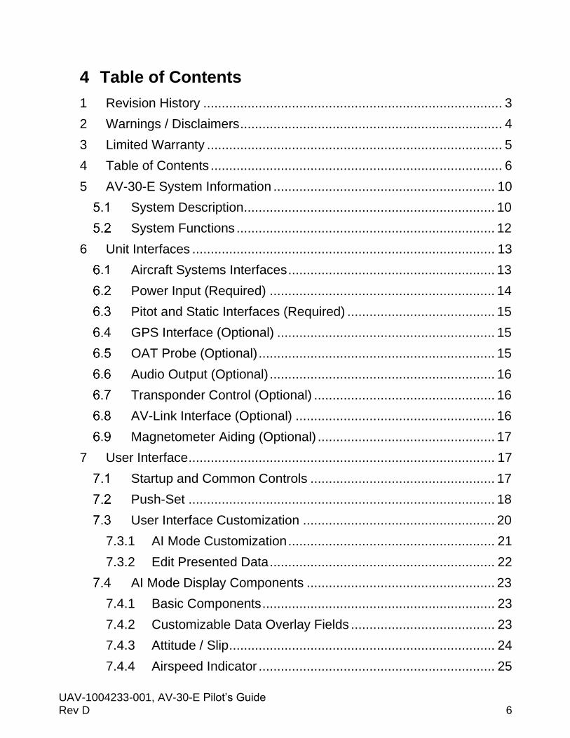
This information includes callsign or flight plan identifier, information
source, type of aircraft, distance, altitude, and airspeed. If an information
item is unavailable, then dashes “---” will appear for the item.
Figure 30 - Traffic Target Tracking Function
The screen will stay in tracking mode until disengaged with a push and
release of the center button. During tracking, the zoom function is
disabled.
7.7.8 Accessing Reversionary AI
A reversionary style display of attitude and slip is available from the traffic
page. Push and release the right button to engage this screen. Push and
release the right button again to disengage.
Distance,
altitude,
and
airspeed.
Callsign or Flight Identifier.
Target type.
Direction of flight,
relative altitude.
Highlighted tracked target.
Descending indicator.

UAV-1004233-001, AV-30-E Pilot’s Guide Rev D Page 43
Figure 31 - Traffic Reversionary AI Activation
When a transponder is interfaced, this page also allows control and
monitoring of the transponder as detailed in §7.8 - Reversionary AI. This
mode page cannot be customized by the pilot.
7.7.9 Traffic Mode Configuration
The traffic mode has settings that can be configured for ownship identity,
to prevent the ownship from being displayed as “ghost” aircraft, and traffic
filtering for reducing the content displayed on the screen.
7.7.9.1 Ownship ICAO
If your aircraft is not equipped with an ADS-B Out system, Air Traffic
Control (ATC) can rebroadcast your Mode-C target to nearby aircraft using
Automatic Dependent Surveillance – Rebroadcast (ADS-R). ADS-R is a
client-based service that relays ADS-B information transmitted by aircraft
on one line to aircraft equipped with ADS-B In on the other link.
If you receive that transmission, it can cause your own aircraft to be
displayed as a nearby target, usually slightly behind you and ± 100 to 200
feet in altitude, from the slight delay in the transmission reaching you due
to the secondary surveillance radar processing and rebroadcasting delay.
Every ADS-B In system occasionally displays a ghost, even for those
aircraft equipped with ADS-B Out. Entering your ownship ICAO can
remove that identified ghost from the traffic screen.

UAV-1004233-001, AV-30-E Pilot’s Guide Rev D Page 44
Ownship ICAO can be entered manually using the OWNSHIP ICAO menu
entry. Once entered, the value is saved but can be changed at any time.
If a uAvionix transponder is installed, and transponder control is enabled,
ownship is automatically detected and entered for you on this screen.
Manual override of this value is not permitted when transponder control is
enabled.
7.7.9.2 Traffic Filtering
Traffic can be filtered by ownship relative altitude to reduce the information
displayed on the screen. Ownship altitude is collected from one of multiple
sources: ownship reports, GPS altitude, ownship barometric altitude.

UAV-1004233-001, AV-30-E Pilot’s Guide Rev D Page 45
Traffic filter selection options are Normal, Above, Below, Only Own and
None. Full descriptions of each of these are found in Table 2 - Traffic Filter
Options.
Figure 32 - Examples of Alternate Filter Values
Table 2 - Traffic Filter Options
Setting Options Description
Filter.
Normal. Filter ownship, traffic above and below 2700 feet
relative to ownship.
Above. Filter ownship, traffic above 8700 feet and below
2700 feet relative to ownship.
Below. Filter ownship, traffic above 2700 feet and below
8700 feet relative to ownship.
Only Own. Filter only ownship.
None. Displays all traffic.
Ownship
ICAO.
Dependent on
registration number.
Press and release, then rotate center knob to select
each number or letter associated with aircraft ICAO.
This will allow for ownship filtering.

UAV-1004233-001, AV-30-E Pilot’s Guide Rev D Page 46
Reversionary AI
Figure 33 - Reversionary Attitude Indicator
The fourth page of the AI and DG operating modes, as well as the second
page of the MFD operating mode, presents a reversionary style display of
attitude and slip. When a transponder is interfaced, this page also allows
control and monitoring of the transponder. This mode page cannot be
customized by the pilot, but the transponder control can. See §7.9 -
Transponder Control for details on transponder control.
Transponder Control
When installed and configured, the AV-30 can be used to control select
uAvionix transponders (including the BeaconX family). The transponder
controls are available on the Reversionary AI page in each mode.
The reversionary AI page is accessed by pressing and releasing the right
button repeatedly until AI appears in lower right corner of the display.
7.9.1 Changing Squawk
• Press and release the center knob.
• Navigate highlighted cursor to desired digit by rotating the knob.
• Press and release the center knob to select the squawk digit to change.
• Rotate the center knob to change the highlighted squawk digit.
• Press and release the center knob to accept the changed squawk.
• Press and release the left button (DONE) to finish and save the setting.

UAV-1004233-001, AV-30-E Pilot’s Guide Rev D Page 47
7.9.2 Changing Flight ID
• Press and release the center knob
• When the Squawk code is displayed, push and hold the center button
again until FLIGHT ID appears
• Press and release to enter the first value
• Rotate center knob to change the Flight ID value. When desired value
appears, push the center knob to accept the value
• Push and release the right button (CLEAR) at any time to clear the
Flight ID completely
• Navigate highlighted cursor to desired character by rotating the knob
• Repeat until the entire Flight ID has been entered
• Press and release the left button (DONE) to finish and save the setting
Note: No spaces are permitted in the FLIGHT ID
7.9.3 Changing Transponder Mode
• Press and release the center knob.
• Press and release the right button to cycle through each mode selection
(STBY, ON, ALT).
• Press and release the left button (DONE) to finish and save the setting.
A. Configured Callsign / Flight ID
B. Current Squawk Code.
C. Mode Selection (STBY, ON, ALT).
D. GPS NIC (integrity metric).
E. GPS NACp (accuracy metric).
F. Pressure Altitude - Green indicates radar interrogation and will change to IDT if IDENT is active.
G. Communication status (OK, TMOUT).
Figure 34 - Transponder Control

UAV-1004233-001, AV-30-E Pilot’s Guide Rev D Page 48
7.9.4 To Send IDENT
• Press and release the left button
7.9.5 Quick Squawk VFR
BeaconX transponders store a VFR squawk code internally. By default,
this is set to 1200 for U.S. operations, but may be changed in the
transponder configuration.
In operation, there are two ways to change the squawk code to the default
VFR code:
• Press and hold the left button until the VFR squawk code is shown in
the SQWK field
- or -
• Press and release the center knob.
• Press and release the center knob to select a squawk digit.
• Press and release the right button to quick squawk VFR
• Press and release the left button (DONE) to finish
Brightness Menu
The brightness menu is activated by pressing and holding the lower right
button until the brightness option appears.
Figure 35 - Brightness Menu

UAV-1004233-001, AV-30-E Pilot’s Guide Rev D Page 49
The left button toggles between AUTO BRT (automatic brightness mode),
and MANUAL BRT (manual brightness mode).
When in manual brightness mode, utilizing the rotary knob, the display
brightness setting can be adjusted from 1 to 100. When in automatic
brightness mode, the display brightness adjusts set automatically based
on the bezel-mounted photocell.
Pressing the DONE button will exit the menu and save the setting.

UAV-1004233-001, AV-30-E Pilot’s Guide Rev D Page 50
8 User Interface and Font Style Options
Three different cosmetic styles and two different fonts are selectable by
the pilot. The three UI styles are LEGACY, EFIS and VINTAGE. The two
font selections are ARIAL and LCD.
Figure 36 - UI Style Options
These settings only effect the displayed colors and font style – all
functional operations are identical regardless of style settings.

UAV-1004233-001, AV-30-E Pilot’s Guide Rev D Page 51
9 Alerts and Alert Limits
There are three alert types.
• Excessive Bank Angle Alerts.
• Excessive G-Load Limit Alerts.
• Excessive Angle of Attack (AoA) Limit Alerts.
Figure 37 shows an example how the visual alerts are displayed.
Figure 37 – Example of Alert Annunciator on Screen
The priority and warning / alert levels, from the lowest priority to the
highest priority are found in Table 3.
UAV-1004233-001, AV-30-E Pilot’s Guide Rev D Page 52
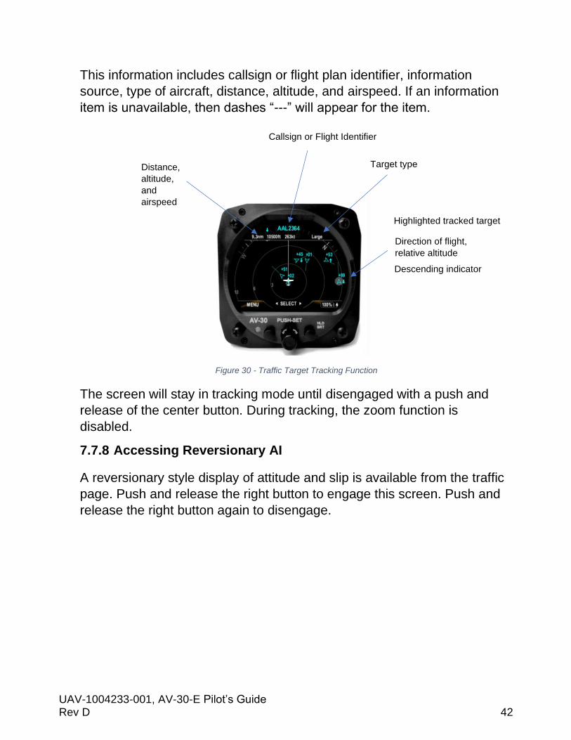
Table 3 - Alert Types and Priorities
.Type. .Priority. .Percent. .Aural. .Visual.
Roll 7 100% “Roll”
AoA 6 80% One Tone
AoA 5 90% Two Tones
AoA 4 100% “Check Angle”
G Limit 3 80% One Tone
G Limit 2 90% Two Tones
G Limit 1 100% “G Limit”
The thresholds for each alert are pilot adjustable, and each alert type can
be independently enabled or disabled.
Pressing the rotary knob when an alert is active will clear alert.

UAV-1004233-001, AV-30-E Pilot’s Guide Rev D Page 53
10 Internal Battery Operation
General
The internal battery consists of a rechargeable battery system with
automatic recharge, self-test, and power switching capability. The internal
battery capacity will provide approximately 2 hours of operation at
standard temperatures and 30 minutes (minimum) of operational capacity
over the operational temperature range.
Battery Transition Logic
The battery is tested, enabled, and disabled based on airspeed and
aircraft bus voltage.
10.2.1 Power-On Self-Test (Pre-Flight)
On powerup, the battery charge status will show “TEST” in amber. During
this process, an internal load is being applied to the battery to determine
general capacity capability. If the battery fails this self-test, the charge
status field will show “FAIL” in red, and no battery capability will be
available.
Figure 38- Battery Test Indicators
If the battery status shows “FAIL”, departure into actual or
planned IFR conditions must not be performed.

UAV-1004233-001, AV-30-E Pilot’s Guide Rev D Page 54
10.2.2 Power Loss, Airspeed Above 40 Knots (In-Flight)
When in flight and the bus voltage drops below 7 VDC, the unit will
automatically transition to internal battery operation; no pilot action is
required for continued operation.
The “ON BATTERY” annunciation will be displayed:
Figure 39 - On Battery Operation
If bus voltage returns, the unit will automatically transition back to aircraft
bus power; no pilot action is required. The “ON BATTERY” annunciation
will extinguish.
10.2.3 Power Loss, Airspeed Below 40 Knots (On-Ground)
When on ground and the bus voltage drops below 7 VDC, the unit will
initiate a shut-down sequence. This is the normal “on-ground” shutdown
method. Pilot may discontinue the shutdown with any knob or button push.
If bus voltage returns, the shutdown sequence will automatically
discontinue, and the unit will return to normal operating mode.
If bus voltage is not returned and the unit remains on, it can be shut down
by pressing and holding the left and right buttons until screen goes black.

UAV-1004233-001, AV-30-E Pilot’s Guide Rev D Page 55
Battery Charge Status
The battery charge state is shown in percentage from 0 to 100. An
internal battery charger will re-charge the battery if bus voltage is above
approximately 10 VDC. The battery charge icon (presented adjacent to
the battery charge state), will be illuminated during the charge cycle as
shown in Figure 40 - Battery Charge Status.
Figure 40 - Battery Charge Status
It is normal for the battery charge icon to intermittently flash during the
battery charge cycle.

UAV-1004233-001, AV-30-E Pilot’s Guide Rev D Page 56
11 AoA Operation and Configuration
The following provides a description of how the derived Angle of Attack
(AoA) operates and presents the corresponding AoA information to the
pilot.
One of the main advantages of an AoA system is that it can provide an
early indication of a stall, bringing enhanced awareness to the pilot.
However, the AV-30-E system is supplemental in nature and
does not replace the functionality provided by the aircrafts
existing stall warning system.
Operational Methodology
Angle of attack is determined by comparing aircraft pitch to the aircraft
flight path angle through the air. In level flight this directly corresponds to
the angle at which the wing is intercepting the body of air surrounding the
aircraft, with correlates to the current AoA.
Pitch is determined by the precision internal AHRS and flight path angle is
determined by air-data based airspeed versus vertical speed
measurements.
Angle Of Attack
Pitch Angle
Flight Path
Level Ref
Pitch Angle = AHRS Measured PitchFlight Path Angle = ADC Vertical Speed / Indicated Airspeed
Figure 41 – AoA Computation
As an example of this relationship, during a climb, if the pitch angle is 10
degrees upward, and the aircrafts flight path through the air (forward

UAV-1004233-001, AV-30-E Pilot’s Guide Rev D Page 57
airspeed and vertical speed) is also 10 degrees upward, the equivalent
AoA is 0 degrees. If, however, the pitch angle is 10 degrees upward, and
the aircrafts flight path through the air is only 5 degrees, this corresponds
to a positive 5-degree AoA.
A second example is where the pitch is 0 degrees, but the aircraft is
descending. The AoA is then equivalent to the descent angle, which will be
a negative AoA.
Configured Limits
As each aircraft make and model has different flight characteristics and
post-production modifications such as altered wing tips, performance kits
and other related modifications may change the flight dynamics of the
aircraft, each aircraft has unique configuration limits that must be set for
proper AoA operation.
An upper and lower configuration limit is pilot adjustable and provides the
scaling mechanism for individual aircraft flight characteristics as it relates
to the corresponding AoA display.
The upper near-stall configuration limit is set when the aircraft is in the
“base-to-final” configuration with flaps and gear set to their normal
positions for this maneuver. This provides the best protection when the
aircraft is low-and-slow, and the pilot may inadvertently stall based on
over-corrections.
• The upper limit is configured to coincide with the aircrafts existing stall
warning system and is typically on the order of 10 to 15 degrees. This
visually correlates to the first red bar on the AoA display with the
second (upper most) red bar providing indication for operation between
the aircrafts stall warning and actual stall point.
• A lower limit is configured to coincide with the AoA at which the aircraft flies under normal cruise conditions. This is typically on the order of 3 to 4 degrees. This visually correlates to the lowest one or two green bars on the AoA display.

UAV-1004233-001, AV-30-E Pilot’s Guide Rev D Page 58
The figure below shows how the configured upper and lower limits are
mapped onto the color coded AoA indication.
Configured Upper Limit
Configured Lower Limit
Level Ref
Total Scale: 2 Red, 2 Yellow, 6 green
Illu
min
ated
Stall Warning
Figure 42 – AoA Upper and Lower Limits
Setting AoA Upper Limit
The objective is to set the upper AoA limit such that the first red bar
illuminates at roughly the same time the aircrafts stall warning occurs.
To set the upper limit, the following procedure is recommended:
• At a safe altitude suitable for stalls, configure the aircraft for the normal
base-to-final turn (typically gear and partial flaps extended).
• Slowly reduce speed and maintain a constant altitude, monitoring the
display AoA as the aircrafts angle of attack increases.
• If the aircrafts stall-warning occurs prior to the indicator reaching the
first red bar, the upper AoA limit needs to be numerically lowered to
coincide with the aircrafts stall-warning point.
• If the aircrafts stall-warning occurs after the indicator has reached the
first red bar, the upper AoA limit needs to be numerically raised to
coincide with the aircrafts stall-warning point.

UAV-1004233-001, AV-30-E Pilot’s Guide Rev D Page 59
• See the Setup Menu instructions and adjust the upper limit.
• Repeat the above procedure as required.
Setting AoA Lower Limit
The objective is the set the AoA lower limit to correspond with normal en-
route operation with one or two lower green bars illuminated.
• Configure the aircraft for normal en-route operation (typically gear
retracted and flaps fully retracted) and observe the AoA indication.
• If more than 2 “green” bars are showing, the lower AoA limit needs to
be numerically lowered.
• If no “green” bars are showing, the lower AoA limit needs to be
numerically increased.
• See the Setup Menu instructions and adjust the lower limit.
• Repeat the above procedure as required.

UAV-1004233-001, AV-30-E Pilot’s Guide Rev D Page 60
AoA Alert Types and Thresholds
Angle of attack alerts consist of both aural and visual alerts. Three alert
levels are provided and are triggered on how close the current AoA is to
the configured upper limit (as a percentage).
Table 4 - AoA Alert Limits
.Level. .Percent. .Aural. .Visual.
Alert 1. 80%. One Tone.
Alert 2. 90%. Double Tone.
Alert 3. 100%. “Check Angle”.
When an alert is being generated, pressing any button will mute the alert.
AoA alerts can also be completely disabled under the pilot preference
settings.
Flap Setting Observations
When the upper AoA limit is configured for the “base-to-final” flap setting,
and the lower AoA limit is configured for the normal “cruise” flap
configuration, the indicated AoA will vary from this baseline when flaps are
configured for other phases of flight. The pilot should document the actual
indications provided for the various phases of flight.
In Table 5, please highlight the actual AoA presentation for the indicated
phase of flight.

UAV-1004233-001, AV-30-E Pilot’s Guide Rev D Page 61
Table 5 - AoA Observations
Flap Setting Flaps Up Flaps Down
Pre-Stall.
Climb Vx.
Climb Vy.
Cruise.
Best Glide Speed.
Approach.
1.3 Vs.
1.2 Vs.
1.1 Vs.

UAV-1004233-001, AV-30-E Pilot’s Guide Rev D Page 62
12 Setup Menu
The setup menu allows customization of settings that are pilot-accessible.
Installer-only related settings are found in AV-30-E Installation Manual.
Installation settings must be adjusted on the ground.
To access the Setup Menu, push the Menu button twice until the SETUP is
shown in the lower window.
Figure 43 – Setup Menu Access
Rotating the knob left and right will access the various parameters that may be configured.
Figure 44 - AOA Alert Setting
Pressing the knob when the desired field is shown will allow the associated setting to be adjusted. After adjustment, pressing the knob again will exit editing mode. Pressing DONE or a lack of user input for 30 seconds will exit the setup menu and return to the primary screen.
Table 6 contains all the setup menu settings.

UAV-1004233-001, AV-30-E Pilot’s Guide Rev D Page 63
Table 6 - Setup Menu Settings
Setting Description Options / Setting Range
UI STYLE. Sets Visual Style. LEGACY, EFIS, VINTAGE.
UI FONT. Sets Font Style. ARIAL, LCD.
AUDIO VOL. Audio Volume for Alerts. 1 to 10.
AOA ALERT. Enable AoA Alerts. DISABLED, ENABLED.
AOA HIGH LIM*. Upper AoA Limit. 7 to 30.
AOA LOW LIM*. Lower AoA Limit. -30 to 5.
G ALERT. Enable G Load Alert. DISABLED, ENABLED.
G POS LIM. Positive G Limit. 2 to 8.
G NEG LIM. Negative G Limit. -1 to -8.
ROLL ALERT. Enable Roll Alert. DISABLED, ENABLED.
ROLL LIM. Roll Alert Threshold. 30 to 80.
TRAK STAB. Inertial Track Smoothing. DISABLED, ENABLED.
HOURS. Lifetime hours of operation. For reference.
* Note: AoA limits cannot be changed unless the installation menu is enabled. Only enabling or disabling AoA Alerts is permitted when installation menu is disabled.

UAV-1004233-001, AV-30-E Pilot’s Guide Rev D Page 64
13 AV-Link
Overview
The AV-Link is an integrated Wi-Fi bridge that allows for communication
between AV-30-E and Wi-Fi enabled devices.
Figure 45 - AV-Link Attached to AV-30-E
The AV-Link allows for the integration of portable ADS-B devices such as
Sentry and Sentry Mini to provide ADS-B traffic and GPS to an AV-30-E.
Software updates for the AV-Link and AV-30 can be performed via the
embedded web page. AV-Link configuration settings and device status are
also accessible through the embedded web page.
The AV-Link accessory is not powered by the AV-30-E internal
battery. Wi-Fi traffic data provided to the MFD mode will be
unavailable during a power loss.
Additional Required Equipment
AV-Link is designed to interface with an existing Wi-Fi capable ADS-B
receiver and the AV-30 EXP display. To fully take advantage of the AV-
Link, the following equipment is required:
• AV-30-E Display
• ADS-B Receiver with GPS and Wireless capability

UAV-1004233-001, AV-30-E Pilot’s Guide Rev D Page 65
Connecting
Support for Windows, MacOS, iOS and other devices are supported, using
the built-in web browser support on your computer. To connect to the AV-
Link, configure your computer to connect to the AV-Link Wi-Fi connection.
1. Power the AV-Link by attaching AV-Link to AV-30-E to provide
power. See AV-30-E Installation Manual for details.
2. Once the AV-Link is powered, on your computer, connect to the AV-
Link Wi-Fi hotspot, which will have a “AV_XXXX” SSID, where XXXX
is a combination of alpha-numeric characters.
3. Once connected, use your web browser to navigate to 192.168.4.1.
From there, you will see the AV-Link main web page.

UAV-1004233-001, AV-30-E Pilot’s Guide Rev D Page 66
Home Page
Note: Accessing the AV-Link web
pages while in flight is not
recommended and may disrupt normal
operations of the AV-Link. All settings
changes should be performed while on
the ground.
The AV-Link main web home page
provides both status information and
methods to control settings. The
screen is separated into three
sections, the Settings, Status, and
connected Device Information.
13.4.1 Settings
The settings panel contains
information about the AV-Link. The
firmware version, the AV-Link SSID,
number of clients connected to the AV-
Link and information about any ADS-B
receiver connected via Wi-Fi.
13.4.2 Status
When connected to an ADS-B receiver, information received such as the
ownship ICAO address, callsign, GPS location information as well as the
current altitude is frequently updated.
13.4.3 Device Information
Connected devices, such as the uAvionix AV-30-E display or the Sentry
ADS-B receiver, will be shown with the device serial number and version,
if available. When the device is disconnected, it is removed from this list.

UAV-1004233-001, AV-30-E Pilot’s Guide Rev D Page 67
13.4.4 Navigating to Other Pages
Navigating to other AV-Link web pages is done using the web links at the
bottom of the page.
Wi-Fi Settings is used to configure the AV-Link and ADS-B Wi-Fi settings,
Statistics is used to provide access to real-time system statistics and AV
Firmware Update is used to update a connected AV-30 display with new
firmware.

UAV-1004233-001, AV-30-E Pilot’s Guide Rev D Page 68
Wi-Fi Settings Page
The AV-Link Wi-Fi settings page provide a
way for the user to configure wireless
connections. The screen is separated into
two sections, the main Wi-Fi settings for
the AV-Link (upper) and Wi-Fi settings for
connecting to a remote ADS-B receiver
(lower).
This will cover the lower settings section.
13.5.1 ADS-B Receiver Settings
SSID
This is the Service Set Identifier (SSID) and is the primary name that is
used for connecting to a remote ADS-B receive via Wi-Fi. If this value is
set, the AV-Link will first attempt to connect to the named device.
When the AV-Link scans for available ADS-B receivers, the SSID drop
down list is populated with the device names that it discovers.
If a custom ADS-B is desired, select ‘Enter a custom receiver’ and enter
the name of the custom device.
If removing the custom ADS-B receiver is desired, select ‘Remove custom
receiver’ and click Save.
AUTO CONNECT
By default, AV-Link will automatically identify preferred uAvionix™ ADS-B
devices and connect to them, making the initial use very simple.
Figure 46 - AV-Link Wi-Fi Settings

UAV-1004233-001, AV-30-E Pilot’s Guide Rev D Page 69
If AV-Link has been configured with a preferred device and the named
device is not available and Auto Connect is checked, then AV-Link will
attempt to connect to any of the preferred uAvionix™ ADS-B devices it
discovers.
If Auto Connect is checked, AV-Link will attempt to discover and
automatically connect to uAvionix preferred ADS-B receivers. Examples of
these are:
• Sentry.
• Sentry Mini.
• SkyEcho.
• echoUAT.
• skySensor.
Unchecking Auto Connect will disable auto-discovery of uAvionix preferred
ADS-B devices.
PASSWORD
If password security is used on the ADS-B receiver, entering a password
into this field, and clicking on Save will set this password. The password
must be a minimum of 8 characters to meet security requirements.
PORT
If the ADS-B receiver being used transmits GDL90 packets on a port that
is different than 4000, entering the port number and clicking on Save will
set this custom port. Valid values are 1-65535.
STATUS
This status reference will frequently update with the current status of the
Wi-Fi connection to your ADS-B receiver.

UAV-1004233-001, AV-30-E Pilot’s Guide Rev D Page 70
14 Operating Limits & System Specifications Table 7 - Operating Limits
Operating Limits
Attitude Rate Limit. ±250 degrees per second.
Attitude Operational Range. 360° Roll, 180° Pitch.
Attitude Accuracy. 1° Static, 2.5° Dynamic.
Airspeed Operational Range. 40 to 300 kts.
Altitude Operational Range. -1,000 to +25,000 ft.
AoA Operational Range. -30° to +30°.
AoA Resolution. 1°.
AoA Valid Speed Range. +35 to +300 kts.
AoA Accuracy. 2.5°.
DALT Operational Range. -1,000 to +25,000 ft.
DALT Accuracy. ± 500 ft.
TAS Operational Range. +35 to +300 kts.
TAS Accuracy. ± 20 kts.
G-Load Operational Range. ± 8 g.
OAT Operational Range. -40°C to +70°C.
OAT Accuracy. ±4°C.
Bus Voltage Range. 7 to 35 Volts.
Bus Voltage Accuracy. ±1.0 Volt.
Recommended