R. I.
TU Darmstadt 1 2016
Automotive Control Systems -Past, present, and future-
Prof. Dr.-Ing.Rolf Isermann
Technische Universität Darmstadt
Institute of Automatic Control and Mechatronics
Darmstadt, Germany
R. I.
TU Darmstadt 2
Automotive Control Systems
• Introduction
• Mechatronic components and driver assistance systems
• Control structures for automobiles
• Modelling and parameter estimation of vehicle dynamics
• From driver assistance systems to automatic driving
• Collision avoidance systems
• Fault tolerant issues
• Outlook
Outline
R. I.
TU Darmstadt 3
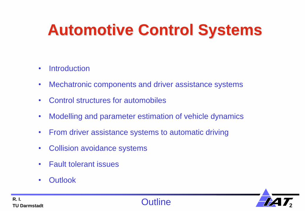
Some general drivers for the development of automobiles
1. Shortage of fossil energy and raw material resources:
• Increasing energy and raw material prices
• Increased use of regenerative energy sources (wind, biofuel, solar), and storage
R. I.
TU Darmstadt 4
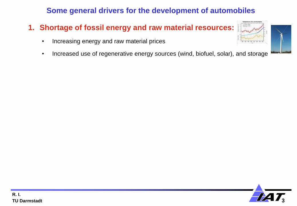
Some general drivers for the development of automobiles
1. Shortage of fossil energy and raw material resources:
• Increasing energy and raw material prices
• Increased use of regenerative energy sources (wind, biofuel, solar), and storage
2. Increasing transportation and mobility
• More traffic (ground, air, sea)
• Energy/time efficient mobility concepts

R. I.
TU Darmstadt 5
Some general drivers for the development of automobiles
1. Shortage of fossil energy and raw material resources:
• Increasing energy and raw material prices
• Increased use of regenerative energy sources (wind, biofuel, solar), and storage
2. Increasing transportation and mobility
• More traffic (ground, air, sea)
• Energy/time efficient mobility concepts
3. Improvement of safety for automobiles
• Passive safety
• Active safety

R. I.
TU Darmstadt 6
Some general drivers for the development of automobiles
1. Shortage of fossil energy and raw material resources:
• Increasing energy and raw material prices
• Increased use of regenerative energy sources (wind, biofuel, solar), and storage
2. Increasing transportation and mobility
• More traffic (ground, air, sea)
• Energy/time efficient mobility concepts
3. Improvement of safety for automobiles
• Passive safety
• Active safety
4. Increasing electrification and electronification
• Electronic sensors, electrical actuators, electronic control units
• Integration to mechatronic components
• Power trains with combustion engines and/or electrical motors

R. I.
TU Darmstadt 7
Automotive Control Systems
• Introduction
• Mechatronic components and driver assistance systems
• Control structures for automobiles
• Modelling and parameter estimation of vehicle dynamics
• From driver assistance systems to automatic driving
• Collision avoidance systems
• Fault tolerant issues
• Outlook
Outline

R. I.
TU Darmstadt 8
Source: Rainer Kallenbach, Bosch 2010: DSC Conference. Cambridge (historical Bosch archive)
No electronics,
except the radio
Electrical system of a passenger car in1958
• Alternator
• Battery
• Starter
• Ignition
• Lights
• Blinker
• Horn ….

R. Isermann
TU Darmstadt
Sensors
wheel speed
pedal position
yaw rate
lateral & longitudinal
acceleration
susp. deflection
brake pressure
steering angle
steering torque
ultra sonic
Radar system
video camera
system
stereo camera
system
Mechatronic components and driver-assistance
systems
Actuators
hydraulic pump
magnetic switching
valves
electronic throttle valve
electro-pneumatic brake
booster
semi-active shock
absorbers
electric power steering
magnetic proportional
valves
rear axle steering
torque vectoring
electro-hydraulic or
electromotoric stabiliser
Development of driver-assistance systems

R. Isermann
TU Darmstadt
Sensors
wheel speed
pedal position
yaw rate
lateral & longitudinal
acceleration
susp. deflection
brake pressure
steering angle
steering torque
ultra sonic
Radar system
video camera
system
stereo camera
system
Mechatronic components and driver-assistance
systems Antilock brakes
(ABS, 1979)
→Highly automated driving (20xxx)
→Anti-collision-avoidance (20xx)
Traction control (TCS,
1986)
Brake assist
(BA, 1996)
Electronic air suspension
control (EAS, 1998)
Adaptive cruise control
(ACC, 1999)
Active body control
(ABC, 1999)
Electro-hydraulic brake (EHB,
2001)
Dynamic drive control (DDC,
2003)
Parking assistance (2003)
Continuous damping control
(CDC, 2002) Electrical power steering
(EPS, 1996)
Electronic stability
program (ESP, 1995) Active front steering
(AFS, 2003)
Actuators
hydraulic pump
magnetic switching
valves
electronic throttle valve
electro-pneumatic brake
booster
semi-active shock
absorbers
magnetic proportional
valves
electromotoric actuator
for active front steering
electro-hydraulic or
electromotoric
stabiliser
Development of driver-assistance systems

R. I.
TU Darmstadt 11
Source: Alexander Haeussler; Bosch; Automated Driving …, ATZ Conf. ChassisTec ,Munic h 2015
From hydraulic brake systems to mechatronic brake systems
VMC: Vehicle Motion Control
Conventional
hydraulic brake
with vacuum
booster
Electronic
modulation
ABS, ASC
Deceleration,
acceleration
with ACC
ACC plus
steering
system,
expanded VMC
Electric booster,
redundanccy
for steering
R. I.
TU Darmstadt 12
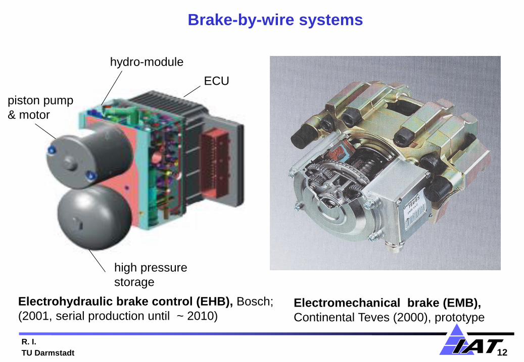
hydro-module
ECU
high pressure
storage
piston pump
& motor
Electrohydraulic brake control (EHB), Bosch;
(2001, serial production until ~ 2010)
Electromechanical brake (EMB),
Continental Teves (2000), prototype
Brake-by-wire systems
R. I.
TU Darmstadt 13
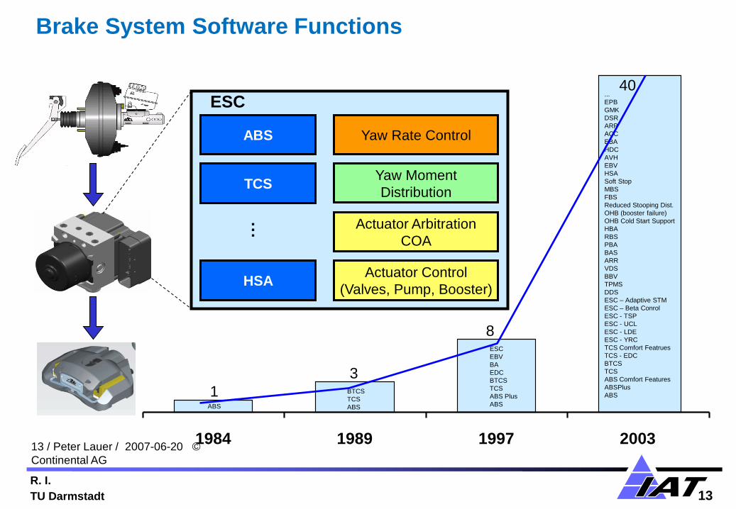
13 / Peter Lauer / 2007-06-20 ©
Continental AG
40
3
1
8
1984 1989 1997 2003
ESC
EBV
BA
EDC
BTCS
TCS
ABS Plus
ABS
...
EPB
GMK
DSR
ARP
ACC
EBA
HDC
AVH
EBV
HSA
Soft Stop
MBS
FBS
Reduced Stooping Dist.
OHB (booster failure)
OHB Cold Start Support
HBA
RBS
PBA
BAS
ARR
VDS
BBV
TPMS
DDS
ESC – Adaptive STM
ESC – Beta Conrol
ESC - TSP
ESC - UCL
ESC - LDE
ESC - YRC
TCS Comfort Featrues
TCS - EDC
BTCS
TCS
ABS Comfort Features
ABSPlus
ABS BTCS
TCS
ABS ABS
Brake System Software Functions
Yaw Rate Control ABS
TCS
Actuator Arbitration
COA
HSA
Yaw Moment
Distribution
…
ESC
Actuator Control
(Valves, Pump, Booster)

R. I.
TU Darmstadt 14
Hydraulic
Power Steering
(HPS)
Electrical
Power Steering
(EPS)
Electrical Power
Assisted Steering
(HPS + EPS)
Active Front
Steering
(AFS)
Steer-by-
Wire
(SbW)
Mechatronic steering systems

R. I.
TU Darmstadt 15
Automotive Control Systems
• Introduction
• Mechatronic components and driver assistance systems
• Control structures for automobiles
• Modelling and parameter estimation of vehicle dynamics
• From driver assistance systems to automatic driving
• Collision avoidance systems
• Fault tolerant issues
• Outlook
Outline
R. I.
TU Darmstadt 16
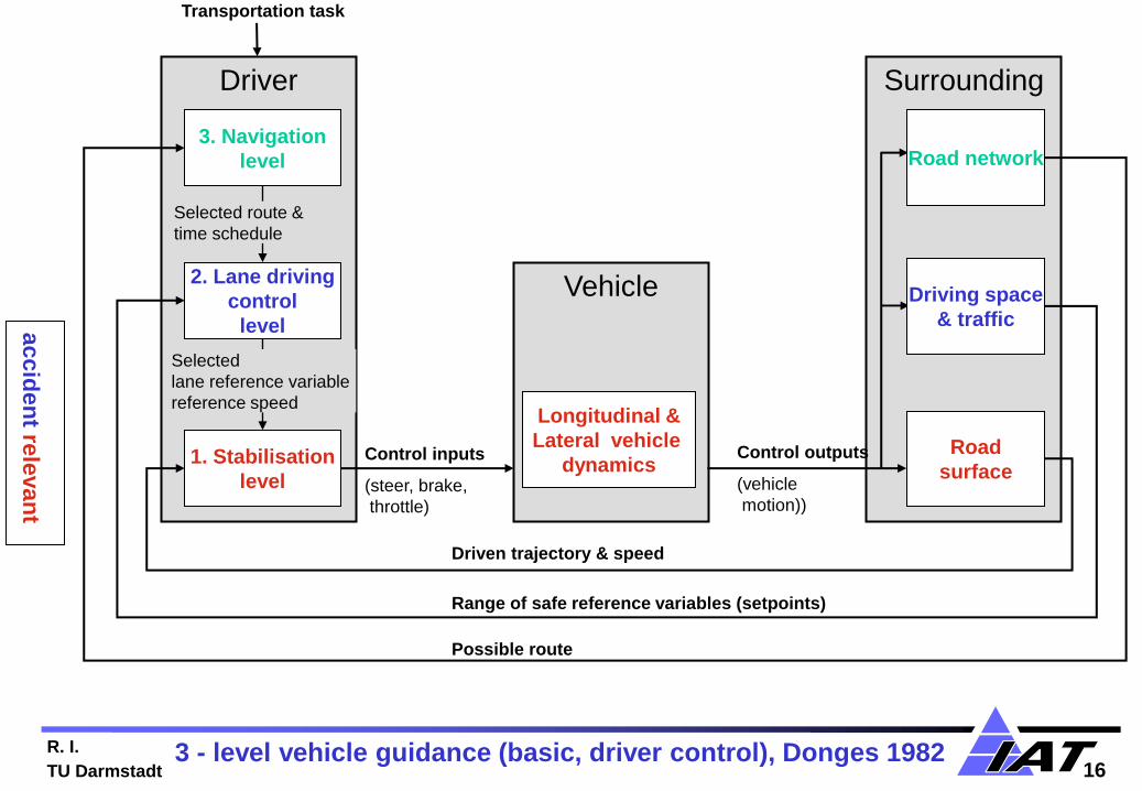
Driver Surrounding
Vehicle
3. Navigation
level
2. Lane driving
control
level
1. Stabilisation
level
Road
surface
Longitudinal &
Lateral vehicle
dynamics Control inputs
(steer, brake,
throttle)
Control outputs
(vehicle
motion))
Selected route &
time schedule
Selected
lane reference variable
reference speed
Transportation task
Driven trajectory & speed
Range of safe reference variables (setpoints)
Possible route
Road network
Driving space
& traffic
3 - level vehicle guidance (basic, driver control), Donges 1982
accid
en
t rele
van
t

R. Isermann
TU Darmstadt
Signal flow: manual driving, some driver assistance systems
→ „peaceful coexistence“

R. I.
TU Darmstadt 18
Source: Peter Lauer, Continental AG, Frankfurt

R. I.
TU Darmstadt 19
Signal flow: with advanced driver assistance systems
and decentralized control
R. I.
TU Darmstadt 20
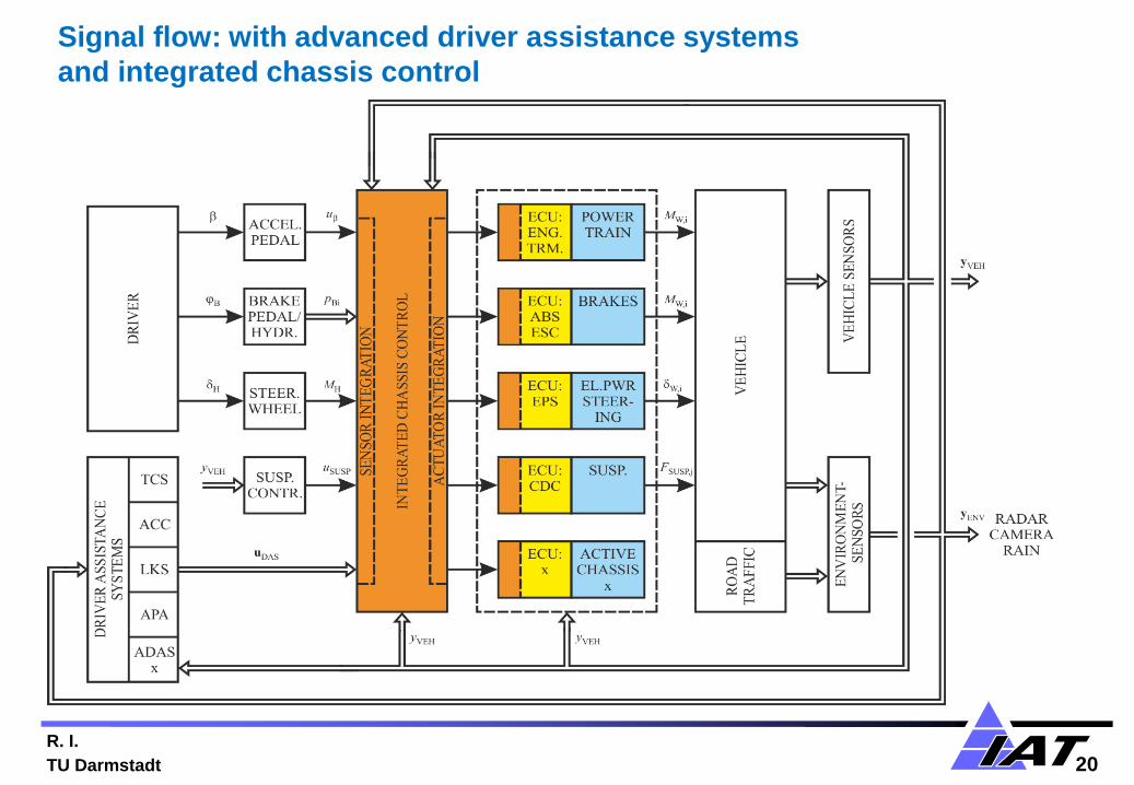
Signal flow: with advanced driver assistance systems
and integrated chassis control
R. I.
TU Darmstadt 21
ADC ECUESC ECU
AUTOSAR
Interface
ESC
SW-C
AUTOSAR
Interface
Vehicle
Model
SW-C
AUTOSAR
Interface
Situation
Recognition
SW-C
AUTOSAR
Interface
Chassis
Arbitration
SW-C
AUTOSAR
Interface
Sensor
SW-C
AUTOSAR
Interface
Actuator
SW-C
AUTOSAR
Interface
Suspension
SW-C
RTE
Basic Software
RTE
Basic Software
AUTOSAR
Interface
Actuator
SW-C
EPS ECU
AUTOSAR
Interface
Steering
SW-C
RTE
Basic Software
AUTOSAR
Interface
Actuator
SW-C
AUTOSAR
Interface
Sensor
SW-C
ACR ECU
AUTOSAR
Interface
Actuator
SW-C
RTE
Basic Software
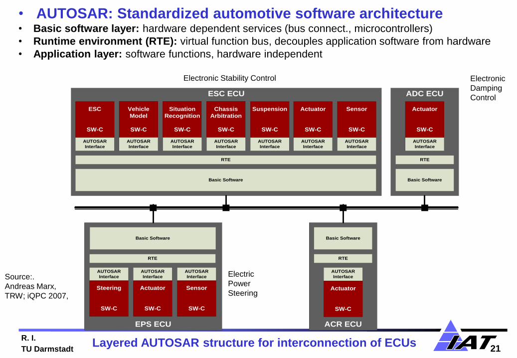
• AUTOSAR: Standardized automotive software architecture • Basic software layer: hardware dependent services (bus connect., microcontrollers)
• Runtime environment (RTE): virtual function bus, decouples application software from hardware
• Application layer: software functions, hardware independent
Source:.
Andreas Marx,
TRW; iQPC 2007,
Electronic Stability Control
Electric
Power
Steering
Electronic
Damping
Control
Layered AUTOSAR structure for interconnection of ECUs
R. I.
TU Darmstadt 22
Automotive Control Systems
• Introduction
• Mechatronic components and driver assistance systems
• Control structures for automobiles
• Modelling , state and parameter estimation of vehicle dynamics
• From driver assistance systems to automatic driving
• Collision avoidance systems
• Fault tolerant issues
• Outlook
Outline
R. I.
TU Darmstadt 23
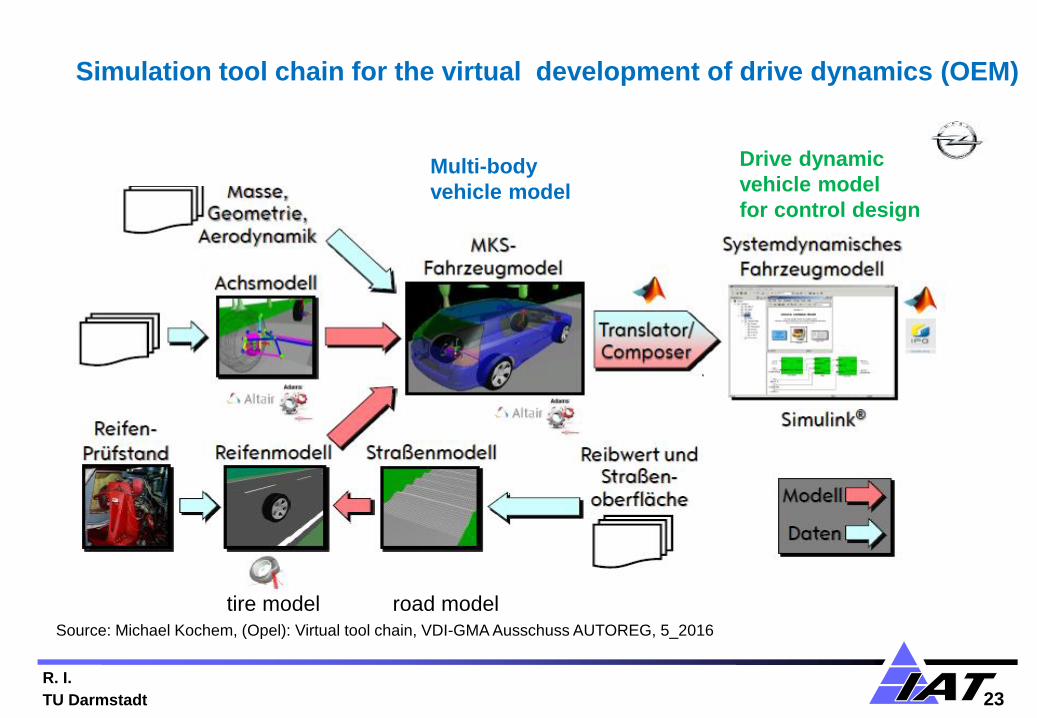
Source: Michael Kochem, (Opel): Virtual tool chain, VDI-GMA Ausschuss AUTOREG, 5_2016
Simulation tool chain for the virtual development of drive dynamics (OEM)
Multi-body
vehicle model
Drive dynamic
vehicle model
for control design
tire model road model
R. I.
TU Darmstadt 24
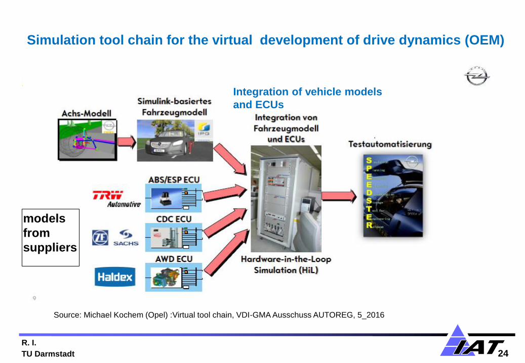
Source: Michael Kochem (Opel) :Virtual tool chain, VDI-GMA Ausschuss AUTOREG, 5_2016
Simulation tool chain for the virtual development of drive dynamics (OEM)
models
from
suppliers
Integration of vehicle models
and ECUs
R. I.
TU Darmstadt 25
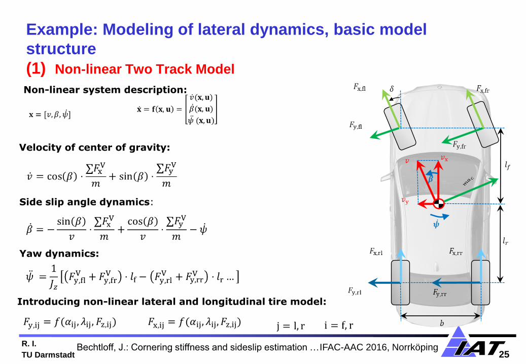
Velocity of center of gravity:
Example: Modeling of lateral dynamics, basic model
structure
(1) Non-linear Two Track Model
Side slip angle dynamics:
Yaw dynamics:
Introducing non-linear lateral and longitudinal tire model:
Non-linear system description:
Bechtloff, J.: Cornering stiffness and sideslip estimation … IFAC-AAC 2016, Norrköping

R. I.
TU Darmstadt 26
Modeling of lateral dynamics: tire forces
(2) Non-linear One Track Model
Non-linear axle force models for front and rear axle:
Linearized region → cornering stiffness
(Rear axle)
(Front axle)
Bechtloff, J.: Cornering stiffness and sideslip estimation …IFAC-AAC 2016, Norrköping
Side slip angle
Lateral
tire
force
R. I.
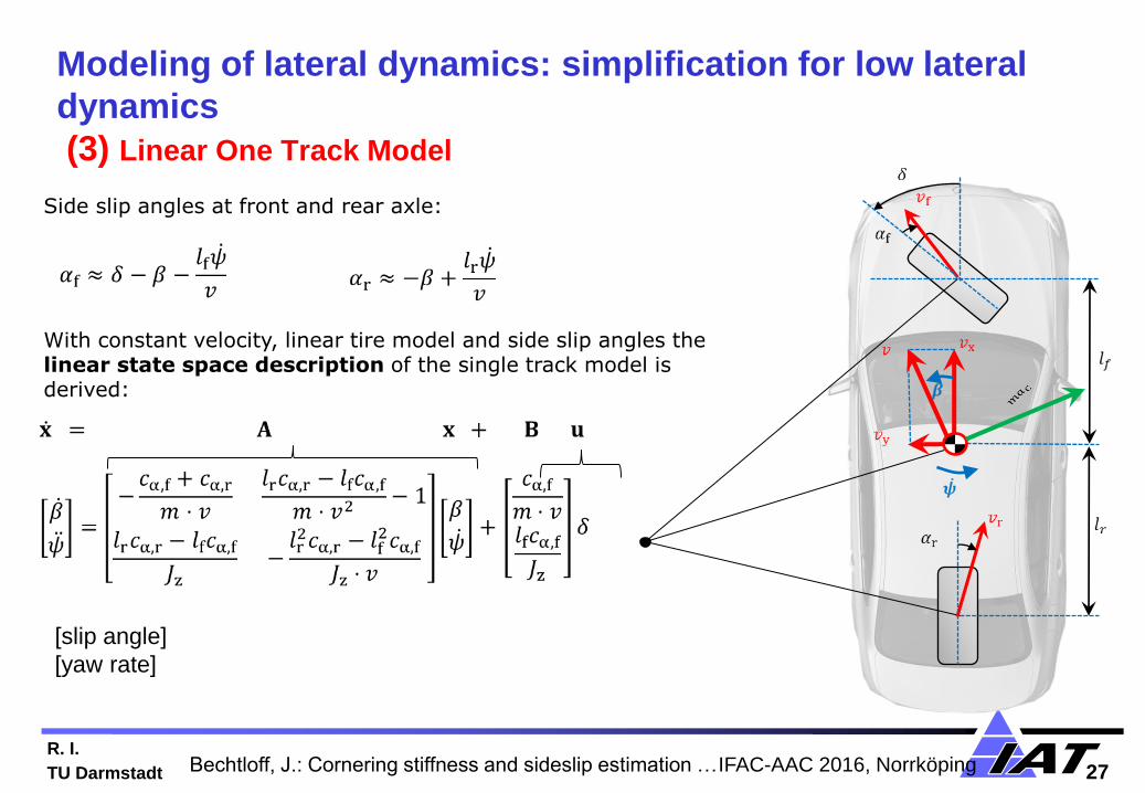
TU Darmstadt 27
Modeling of lateral dynamics: simplification for low lateral
dynamics
(3) Linear One Track Model
Side slip angles at front and rear axle:
With constant velocity, linear tire model and side slip angles the linear state space description of the single track model is derived:
[slip angle]
[yaw rate]
Bechtloff, J.: Cornering stiffness and sideslip estimation … IFAC-AAC 2016, Norrköping

R. I.
TU Darmstadt 28
Modeling of lateral dynamics: ranges for linear and nonlinear
tire forces
(4) Non-linear One Track Model
Non-linear axle force models for front and rear axle:
linear one track model:
area that is covered by the non-linear one track model:
Bechtloff, J.: Cornering stiffness and sideslip estimation … IFAC-AAC 2016, Norrköping
R. I.
TU Darmstadt 29
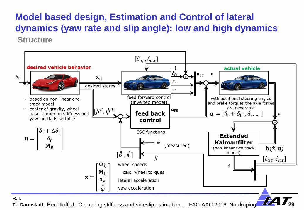
feed back control
Extended Kalmanfilter
(non-linear two track model)
desired vehicle behavior actual vehicle
feed forward control (inverted model)
Model based design, Estimation and Control of lateral
dynamics (yaw rate and slip angle): low and high dynamics
Structure
ESC functions
• based on non-linear one-track model
• center of gravity, wheel base, cornering stiffness and yaw inertia is settable
with additional steering angles and brake torques the axle forces
are generated
(measured)
desired states
wheel speeds
calc. wheel torques
lateral acceleration
yaw acceleration
Bechtloff, J.: Cornering stiffness and sideslip estimation … IFAC-AAC 2016, Norrköping
R. I.
TU Darmstadt 30
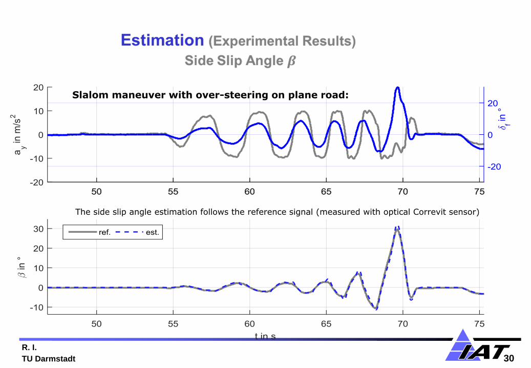
Slalom maneuver with over-steering on plane road:
The side slip angle estimation follows the reference signal (measured with optical Correvit sensor)
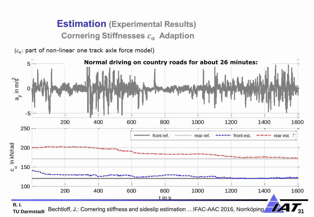
R. I.
TU Darmstadt 31
200 400 600 800 1000 1200 1400 1600
-5
0
5
ay i
n m
/s2
200 400 600 800 1000 1200 1400 1600100
150
200
250
c i
n kN
/ra
d
t in s
VA Ref HA Ref VA IAT HA IAT
200 400 600 800 1000 1200 1400 1600
-5
0
5
ay i
n m
/s2
200 400 600 800 1000 1200 1400 1600100
150
200
250
c i
n kN
/ra
d
t in s
VA Ref HA Ref VA IAT HA IATfront ref. rear ref. front est. rear est.
Normal driving on country roads for about 26 minutes:
Bechtloff, J.: Cornering stiffness and sideslip estimation … IFAC-AAC 2016, Norrköping

R. I.
TU Darmstadt 32
Control design (Simulation)
Example for Active Front Steering
desired vehicle behavior actual vehicle
feed forward control (inverted model)
• based on non-linear one-track model
• cornering stiffness at the front and steering ratio is settable
with additional steering angles the axle forces are generated
fishhook steering angle
stable behavior with AFS
unstable behavior without AFS
desired states
Bechtloff, J.: Cornering stiffness and sideslip estimation …IFAC-AAC 2016, Norrköping → Tueday, 10:40 Hrs

R. I.
TU Darmstadt 33
Automotive Control Systems
• Introduction
• Mechatronic components and driver assistance systems
• Control structures for automobiles
• Modelling and parameter estimation of vehicle dynamics
• From driver assistance systems to automatic driving
• Collision avoidance systems
• Fault tolerant issues
• Outlook
Outline

R. I.
TU Darmstadt 34
Source: Alexander Haeussler; Bosch; Automated Driving …, ATZ Conf. ChassisTec ,Munic h 2015
From assisted driving to automated driving
R. I.
TU Darmstadt 35
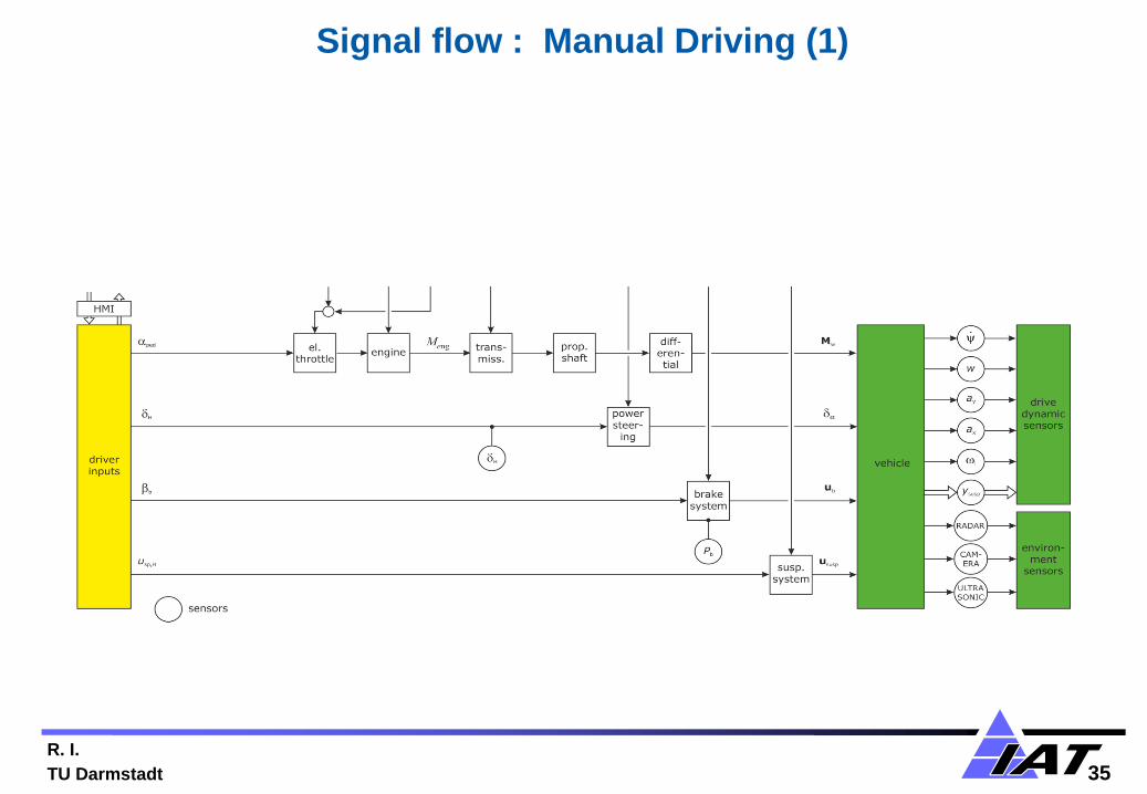
Signal flow : Manual Driving (1)

R. I.
TU Darmstadt 36
Signal flow : Driver and electronic control systems (2a)

R. I.
TU Darmstadt 37
Signal flow : Electronic hierarchical control levels for
automatic driving (2b)
R. Isermann
TU Darmstadt

R. I.
TU Darmstadt 39
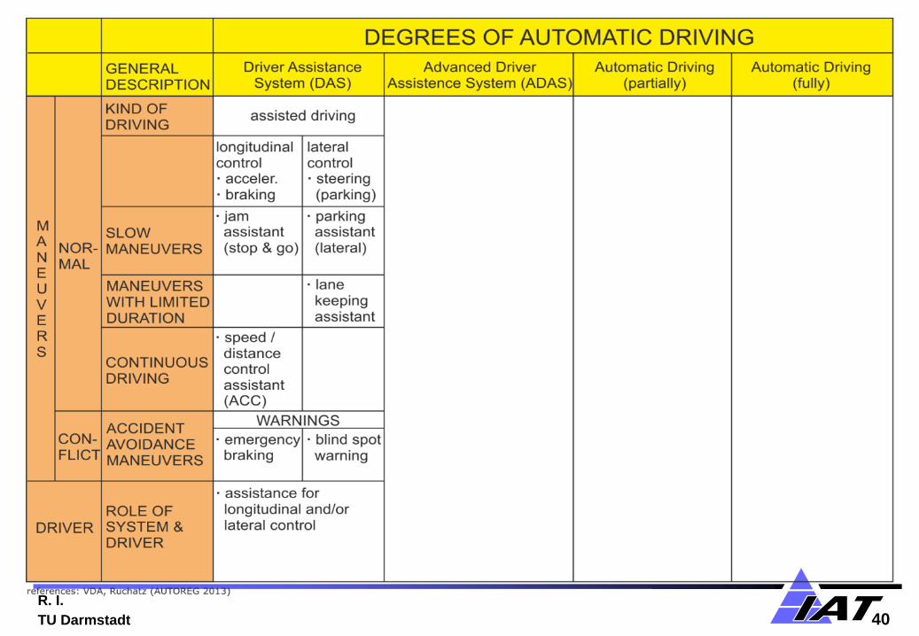
R. I.
TU Darmstadt 40

R. I.
TU Darmstadt 41

R. I.
TU Darmstadt 42

R. I.
TU Darmstadt 43

R. I.
TU Darmstadt 44
Surround sensors: near and long range radar: front and rear,
near and long range infrared, stereo camera, ultra sonic
Source: Gottscholl, VDI/GMA Techn. C ommittee Meeting 7.62 A UTOREG, 2015
R. I.
TU Darmstadt 45
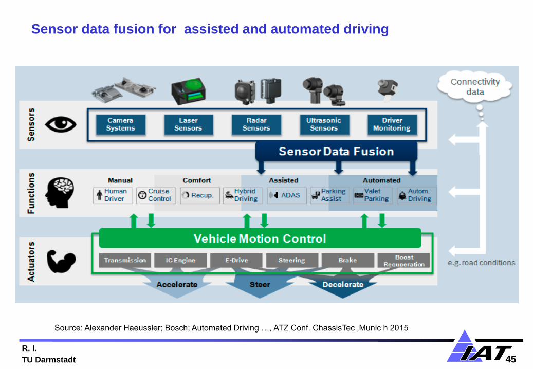
Source: Alexander Haeussler; Bosch; Automated Driving …, ATZ Conf. ChassisTec ,Munic h 2015
Sensor data fusion for assisted and automated driving

R. I.
TU Darmstadt 46
Highly precise position requirements
Source: Gerhard Steiger: Bosch, ATZ-Conf. Driver Assist. Syst.,Frankfurt, 13/14 Apr. 2016
→ Precise, up-to-date maps with high resolution obtained by GPS and link to cloud data
R. I.
TU Darmstadt 47
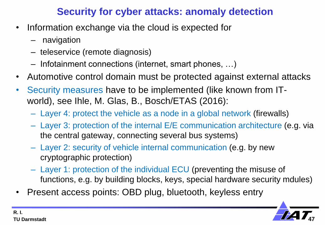
Security for cyber attacks: anomaly detection
• Information exchange via the cloud is expected for
– navigation
– teleservice (remote diagnosis)
– Infotainment connections (internet, smart phones, …)
• Automotive control domain must be protected against external attacks
• Security measures have to be implemented (like known from IT-
world), see Ihle, M. Glas, B., Bosch/ETAS (2016):
– Layer 4: protect the vehicle as a node in a global network (firewalls)
– Layer 3: protection of the internal E/E communication architecture (e.g. via
the central gateway, connecting several bus systems)
– Layer 2: security of vehicle internal communication (e.g. by new
cryptographic protection)
– Layer 1: protection of the individual ECU (preventing the misuse of
functions, e.g. by building blocks, keys, special hardware security mdules)
• Present access points: OBD plug, bluetooth, keyless entry

R. I.
TU Darmstadt 48
4 layer security levels
Source: Markus Ihle; Bosch Center of Competence Security, ATZ Conf. Diver Assist. Syst., Frankfurt, April 2016

R. I.
TU Darmstadt 49
Automotive Control Systems
• Introduction
• Mechatronic components and driver assistance systems
• Control strucures for automobiles
• Modelling and parameter estimation of vehicle dynamics
• From driver assistance systems to automatic driving
• Collision avoidance systems
• Fault tolerant issues
• Outlook
Outline

R. I.
TU Darmstadt 50
Collision avoidance systems: research projects at TU Darmstadt
• Accident type: in longitudinal direction
Vehicles move
same direction
Vehicles move
opposite direction
Other
Vehicles:
• move ahead
• stop
Other
Vehicles:
• move laterally
• cutting in
• crossing
Overtaking:
• rural road
• 2 lanes
→ oncoming
vehicle
Overtaking:
• autobahn
• ≥ 2 lanes
→ oncoming
vehicle,
wrong way
Straight driving:
• own vehicle
turns to left
• other vehicle
turns to left
• CAV
actions:
• warning
• braking
• swerving to
free lane
• warning
• braking
and
• swerving
back
• warning
• braking
and
• swerving
to the right
• warning
• braking &
swerving:
to the right
to free lane
PRORETA 1 (2003 – 2006) PRORETA 2 (2006 – 2009)

R. I.
TU Darmstadt 51
Driver assistance system for obstacle collision avoidance
(PRORETA 1: 2003-2006)
Collision avoiding system: automatic braking and steering
R. Isermann, R. Bruder, H. Winner
E. Bender, M. Darms, M. Schorn, U. Stählin
R. I.
TU Darmstadt 52
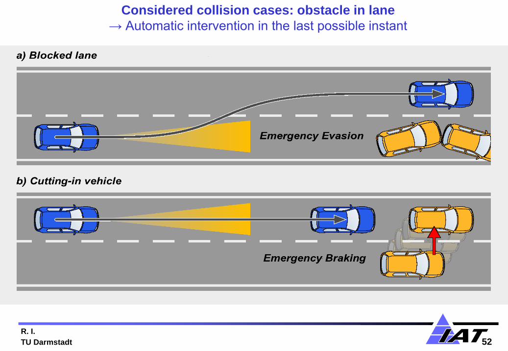
Considered collision cases: obstacle in lane
→ Automatic intervention in the last possible instant
R. I.
TU Darmstadt 53 5
3
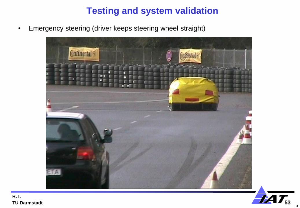
Testing and system validation
• Emergency steering (driver keeps steering wheel straight)

R. I.
TU Darmstadt 54
Driver assistance system for collision avoidance during overtaking
maneuvers , PRORETA 2 (2006-2009)
• Used environmental sensors:
– RADAR-System: Continental ARS 300, wide range, 77 GHz
– Video-System: Continental CSF 200, mono, resolution 752 x 480 pixels
Radar
Kamera
BMW 540 i
R. I.
TU Darmstadt 55
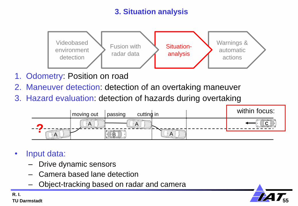
3. Situation analysis
1. Odometry: Position on road
2. Maneuver detection: detection of an overtaking maneuver
3. Hazard evaluation: detection of hazards during overtaking
• Input data:
– Drive dynamic sensors
– Camera based lane detection
– Object-tracking based on radar and camera
A
C
moving out passing cutting in
A
A B
A
?
within focus:
Warnings &
automatic
actions
Situation-
analysis
Fusion with
radar data
Videobased
environment
detection
R. I.
TU Darmstadt 56
C C C
B B B
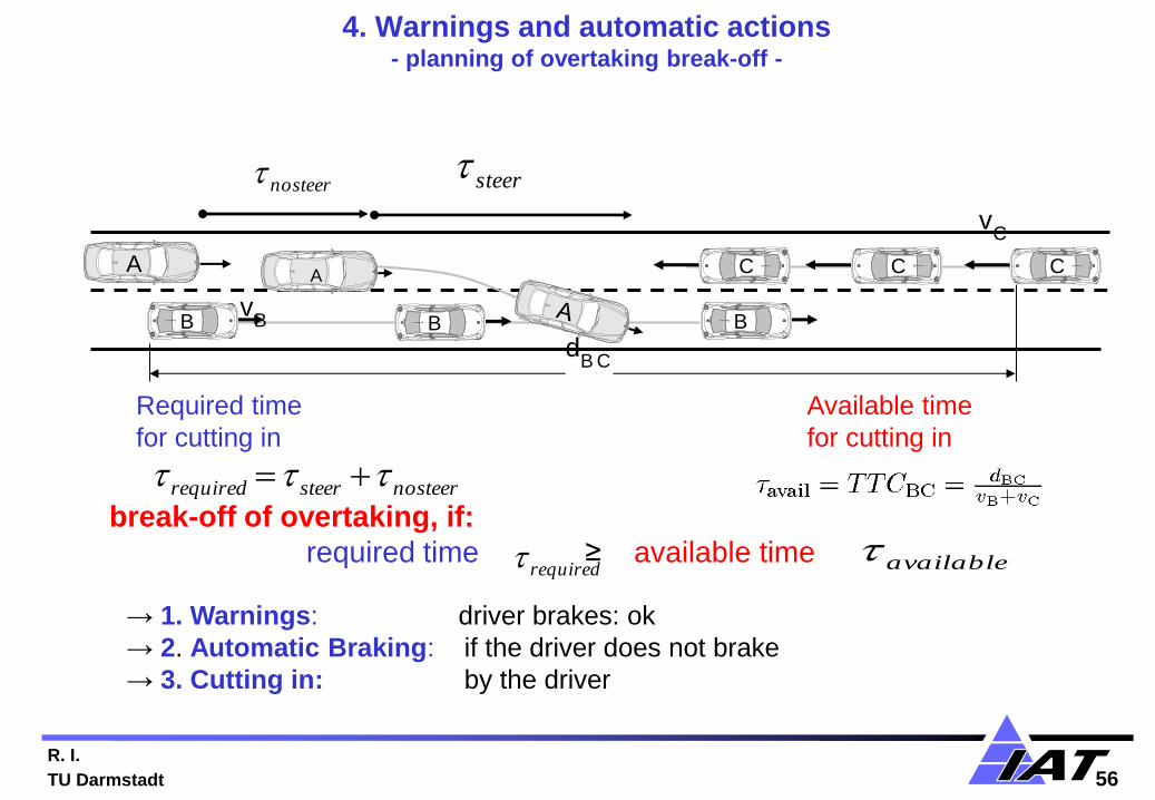
4. Warnings and automatic actions - planning of overtaking break-off -
nosteer steer
nosteersteerrequired
v C
A
v B
d B C
break-off of overtaking, if:
required time ≥ available time
Required time
for cutting in
Available time
for cutting in
required available
A
→ 1. Warnings: driver brakes: ok
→ 2. Automatic Braking: if the driver does not brake
→ 3. Cutting in: by the driver

R. I.
TU Darmstadt 57
Overtaking assistant: PRORETA 2

R. I.
TU Darmstadt 58 58
Overtaking maneuver: warning and automatic braking
R. I.
TU Darmstadt 59
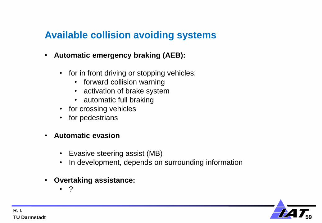
Available collision avoiding systems • Automatic emergency braking (AEB):
• for in front driving or stopping vehicles:
• forward collision warning
• activation of brake system
• automatic full braking
• for crossing vehicles
• for pedestrians
• Automatic evasion
• Evasive steering assist (MB)
• In development, depends on surrounding information
• Overtaking assistance:
• ?
R. I.
TU Darmstadt 60
Automotive Control Systems
• Introduction
• Mechatronic components and driver assistance systems
• Control structures for automobiles
• Modelling and parameter estimation of vehicle dynamics
• From driver assistance systems to automatic driving
• Collision avoidance systems
• Fault tolerant issues
• Outlook
Outline

R. I.
TU Darmstadt 61
Conventional vs. automatic driving
• Conventional driving: driver is always in a control loop for driving
– Controls the vehicle along a route
– Supervises the right functioning of the vehicle
– Obtains warnings for specified faults of some components
– Takes apropriate actions in the case of faults
• Highly automatic driving: driver is temporarily not in a control loop
– Electronic automatic closed loop control systems drive the car
– This is based on sensor signals, digital control algorithms, electrical commanded actuators
– Appearing faults in sensors and actuators influence immediately the closed loop behavior • Small faults may be compensated by the closed loop for some time
• Larger faults may result in control deviations, sluggish behavior, instable behavior (monotonic or oscillatory)
→ safety critical components (sensors, communication channels, electrical board
net, actuators)
need a fault tolerant design

R. I.
TU Darmstadt 62
c) Dynamic redundancy: cold standby
(larger transfer time) n = 2; 1 fault tolerated
b) Dynamic redundancy: hot standby
(small transfer time) n = 2; 1 fault tolerated
a) Static redundancy:
n-out-of m voting
n = 3; 1 fault tolerated
n = 5; 2 faults tolerated
Fault-tolerant schemes for electronic hardware
Modules
Fault- detection
Recon- figuration
1 x
2
x i o
Modules
Recon- figuration
1 x
2
x i o
Modules
Voter
1
x x 2
3
n
i o
Fault- detection
Different kinds of redundancy

R. I.
TU Darmstadt 63
Fail Operational (FO)
• System remains operational (after 1 failure)
• Possible, if the component has analytical or hardware redundancy
• In the case of a fault, the system switches from a defect component to an intact
one system reconfiguration
Fail Silent (FSIL)
• Component is switched off in case of fault
• With regard to other components, the faulty components is silent, i.e. other
components are not affected by the faulty component
Fail Safe (FS)
• Component is brought to safe state and is switched off
• Differentiation: active and passive fail-safe
• Operation cannot be maintained in case of a fault
Degradation steps of fault-tolerant systems
Fail (F)
• Permanent interruption of operation

R. I.
TU Darmstadt 64
Required fault tolerant chassis components
• Brake system
• Electromechanic booster→ redundance by ESC
• Hydraulic brake circuits → redundance by 2 brake circuits
• Electromagnetic valves
• Brake system sensors (positions, currents, pressure, wheel speeds: (4 wheels)
• ECU software functions (ABS, ESC)
• Power steering system (EPS)
• Electromotor
• Steering gear (pinion-rack, ball-recirculation …)
• Steering system sensors (steering angle (redundant), torque, …)
• EPS-ECU software functions
• Chassis sensors
• Acceleration (lateral, longitud. )
• Yaw rate
• Longitudinal speed
• Electric power supply:
• Generation and batteries
→ redundancy is presently only partially implemented ,
→ general hardware redundancy or analytical redundancy
has to be developed
R. I.
TU Darmstadt 65
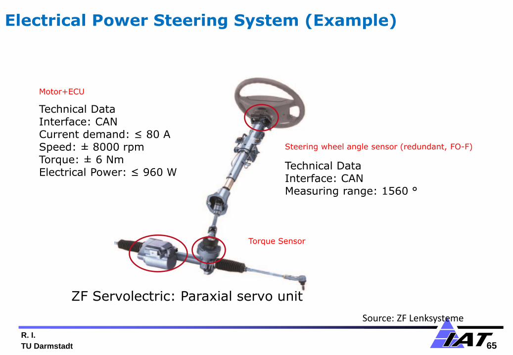
Steering wheel angle sensor (redundant, FO-F)
Technical Data Interface: CAN Measuring range: 1560 °
Torque Sensor
Motor+ECU
Technical Data Interface: CAN Current demand: ≤ 80 A Speed: ± 8000 rpm
Torque: ± 6 Nm Electrical Power: ≤ 960 W
ZF Servolectric: Paraxial servo unit
Source: ZF Lenksysteme
Electrical Power Steering System (Example)

R. Isermann
TU Darmstadt
faults redundancy redundancy redundancy redundancy redundancy
Sensors -
ECU -
Inverter -
Motor - -
Gear - - - - ()
A B C D E
Fault-tolerant structures for EPS systems with increasing redundancy

R. I.
TU Darmstadt 67
dSPACE system PC system
highspeed serial link
force sensor
steering angle steering angle
suspension simulation suspension simulation
a)
b)
Test bench for a duplex EPS (case E) at IAT, TU Darmstadt

R. I.
TU Darmstadt 68
Conclusions and Outlook • Mechatronic components , electrification and surrounding sensor
systems are the basis for advanced driver assistance systems and automatic
driving
• The introduction of (partial) automatic driving occurs step by step, taking
into account reliability, safety and (current) liability
• Virtual development is required and includes :
– Mathematical models (components, vehicle) with different degrees of
granularity (research, suppliers, OEMs)
– Development platforms with SiL, MiL and HiL-Simulation
– Hardware and software prototypes
• Testing and validation: virtual by simulation and by experiments on testing
grounds and with real traffic scenarios
• Electronic architecture changes: real time buses (Flexray, Ethernet), more
integrated control → centralized hierarchical control
• Safety issues: fault-tolerance with redundancy, cyber-security
• Similar developments for model and computer based control of powertrains
(combustion engines, hybrid and electric drives and transmissions)
Recommended