
66 · Application of Laser Hardening Technology to Sintered Parts
FEATURED TOPIC
1. Introduction
Laser hardening is a hardening technology using a laser beam as a heating source.(1) Laser beams have been used for processing and welding widely in the past. In recent years, industrial application of laser hard-ening has been made possible due to technological advancements, resulting in lower equipment cost of laser oscillation machines. We introduced laser hard-ening equipment in March, 2014. As we value the appli-cable reach to the sintered parts of laser hardening, we report the results.
2. The Mechanism of Laser Hardening
Basic components of laser hardening equipment are a laser oscillator, a laser light cable, and laser optics as shown in Fig. 1. A laser spotlight that has a top hat
type profile is usually used in laser hardening. The heating and cooling processes in laser hard-
ening are shown in Fig. 2. The surface of the workpiece irradiated with a laser is heated to austenitizing temper-ature*1 on the 0.1 second time scale. When laser irradia-tion finishes, the heated part is quenched by self-cooling due to heat conduction to the non-heated portion of the workpiece.(2) The surface of the workpiece is hardened by heating in an extremely-limited part and no quenching media. In the case that hardening is
Application of Laser Hardening Technology to Sintered Parts
Makoto SATO*, Yuuki ADACHI and Hiroaki MOTOYAMA
----------------------------------------------------------------------------------------------------------------------------------------------------------------------------------------------------------------------------------------------------------In recent years, industrial application of laser hardening has been made possible due to technological advancements, resulting in lower equipment cost of laser oscillation machines. Laser hardening utilizes surface hardening technology through laser irradiation and generates less heat than induction hardening. Another advantage of laser hardening is its ability to harden the local areas that are not accessible by induction hardening. The use of this technology on sintered parts will lead to new applications due to its inherent advantage in near net shape manufacturing. Laser hardening was performed on various types of sintered materials, and the parts were evaluated for process optimization. Laser hardening was also performed on products in various shapes that are difficult to harden with other surface hardening techniques. The application of this technology for a wide range of products was also investigated.----------------------------------------------------------------------------------------------------------------------------------------------------------------------------------------------------------------------------------------------------------Keywords: sintered parts, laser hardening
Collimation
lens
Focusing
lens
Protective
glass
Laser light cable
Laser oscillator
・Diode laser
・940nm, CW
・Maximum laser power 3kW
beam profile
Laser optics
Top Hat profile
laser beam
workpiece
heated portion
(austenitizing)
laser irradiation
self-cooled portion
(martensitic transformation)
finishing laser irradiation
heat conduction
to non-heated
portion
optical lens
hardenedportion
spotlight
moving directionof the spotlight
Fig. 1. Basic components of laser hardening equipment
Fig. 2. Heating and quenching process in laser hardening
Fig. 3. Laser irradiation

SEI TECHNICAL REVIEW · NUMBER 82 · APRIL 2016 · 67
required for a larger area than the spotlight size, the workpiece is hardened by moving the spotlight.(3) The spot size of the laser beam can be changed from a couple of mm on a side to a dozen mm by changing optical lens.
3. Application Results
3-1 Evaluation of material quality 1 ) Fe-2Cu-0.8C
Laser hardening was performed in standard mate-rial that had a chemical composition of Fe-2Cu-0.8C and its material quality was evaluated. The top view and 5 x 5 mm size cross sections of the part hardened by spotlight are shown in Fig. 4. The microstructure and the Vickers hardness*2 distribution of this section is shown in Fig. 5. The surface had uniform martensitic structure.*3 The self-cooling rate was sufficient to quench this material that had no alloying elements to increase the hardenability. The desired hardness distri-bution was also observed.
2) Fe-2Cu-0.5CSintered material microstructure often becomes less
uniform than conventional steel. Large ferrite grains tend to speck, particularly in material that has a composition of less than 0.7%C. Since the heating time of laser hard-ening is very short, there was a concern about residual ferrite grain after hardening. Therefore, laser hardening
was performed in the material with Fe-2Cu-0.5C chemical composition, and its quality was evaluated. The micro-structure and the hardness distribution of this section is shown in Fig. 6. The microstructure after laser hardening was uniform martensite without residual ferrite. The desired hardness distribution was also observed.
3) Fe-4Ni-0.5Mo-1.5Cu-0.5CLaser hardening was also performed in the material
that had Fe-4Ni-0.5Mo-1.5Cu-0.5C as chemical compo-sition. It had non-homogeneous microstructure in which a variety of metallic phases existed. The microstructure and the hardness distribution of this section are shown in Fig. 7. The microstructure after laser hardening was martensite and Ni-rich austenite. This is similar to the hardening microstructure that is usually obtained by other hardening methods for this material. The desired hardness distribution was also observed.
We confirmed that laser hardening technology is appropriate as a hardening method to sintered material from the above mentioned results.3-2 Applicable shapes
Laser hardening was applied to sintered parts with various shapes. Basically, laser hardening can be applied to any part that can be irradiated by a spotlight.
Hardened layer
5 mm
5 m
m
5 mm
Microstructure observation
Measurement of hardness
distributionTop view Cross sections
Uniform martensitic structure
0100200300400500600700800900
1000
0.0 0.2 0.4 0.6 0.8
Distribution of hardness
Vick
ers h
ardn
ess [
HV0
.2]
Distance from surface [mm]
50μm
Fig. 4. Hardened portion
Fig. 5. Laser hardened portion of Fe-2Cu-0.8C material
Befor hardening(pearlite + ferrite)
After laser hardening(martensite)
0
100
200
300
400
500
600
700
800
0.0 0.2 0.4 0.6 0.8
Distribution of hardness
Vick
ers
hard
ness
[HV0
.2]
Distance from surface [mm]
50μm50μm
Laser
hardening
Befor hardening(bainite + pearlite + ferrite +
Ni-rich austenite)
After laser hardening(martensite +
Ni-rich austenite)
0
100
200
300
400
500
600
700
800
0.0 0.2 0.4 0.6 0.8
Distribution of hardness
Vick
ers h
ardn
ess [
HV0.
2]
Distance from surface [mm]
50μm50μm
Laser
hardeningOnly martensite
structure was
measured.
Fig. 6. Laser hardened portion of Fe-2Cu-0.5C material
Fig. 7. Laser hardened portion of Fe-4Ni-0.5Mo-1.5Cu-0.5C material
68 · Application of Laser Hardening Technology to Sintered Parts
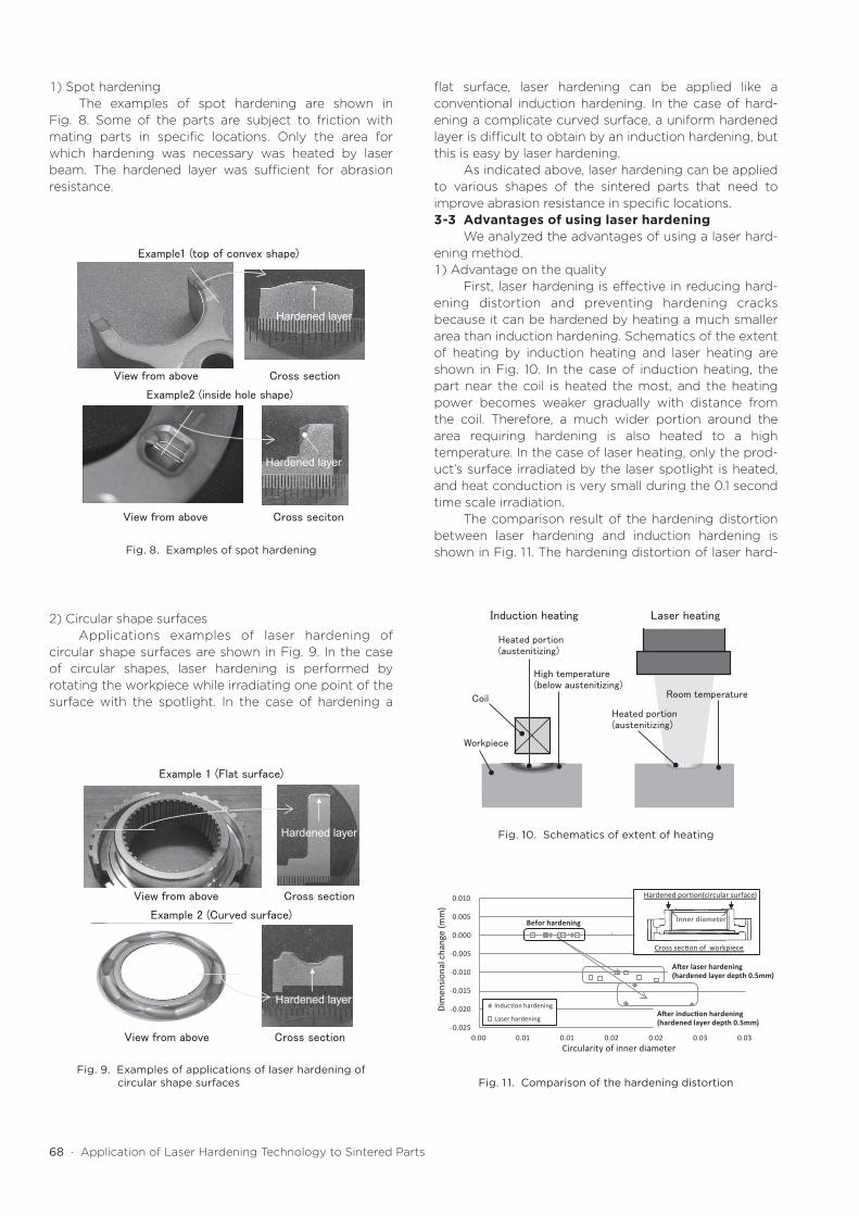
1 ) Spot hardeningThe examples of spot hardening are shown in
Fig. 8. Some of the parts are subject to friction with mating parts in specific locations. Only the area for which hardening was necessary was heated by laser beam. The hardened layer was sufficient for abrasion resistance.
2) Circular shape surfacesApplications examples of laser hardening of
circular shape surfaces are shown in Fig. 9. In the case of circular shapes, laser hardening is performed by rotating the workpiece while irradiating one point of the surface with the spotlight. In the case of hardening a
flat surface, laser hardening can be applied like a conventional induction hardening. In the case of hard-ening a complicate curved surface, a uniform hardened layer is difficult to obtain by an induction hardening, but this is easy by laser hardening.
As indicated above, laser hardening can be applied to various shapes of the sintered parts that need to improve abrasion resistance in specific locations.3-3 Advantages of using laser hardening
We analyzed the advantages of using a laser hard-ening method. 1 ) Advantage on the quality
First, laser hardening is effective in reducing hard-ening distortion and preventing hardening cracks because it can be hardened by heating a much smaller area than induction hardening. Schematics of the extent of heating by induction heating and laser heating are shown in Fig. 10. In the case of induction heating, the part near the coil is heated the most, and the heating power becomes weaker gradually with distance from the coil. Therefore, a much wider portion around the area requiring hardening is also heated to a high temperature. In the case of laser heating, only the prod-uct’s surface irradiated by the laser spotlight is heated, and heat conduction is very small during the 0.1 second time scale irradiation.
The comparison result of the hardening distortion between laser hardening and induction hardening is shown in Fig. 1 1. The hardening distortion of laser hard-
Example1 (top of convex shape)
Example2 (inside hole shape)
View from above Cross section
View from above Cross seciton
Hardened layer
Hardened layer
Induction heating Laser heating
Heated portion(austenitizing)
Coil
Workpiece
Heated portion(austenitizing)
High temperature(below austenitizing)
Room temperature
-0.025
-0.020
-0.015
-0.010
-0.005
0.000
0.005
0.010
0.00 0.01 0.01 0.02 0.02 0.03 0.03
Induction hardening
Laser hardening
Circularity of inner diameter
Dim
ensio
nal c
hang
e (m
m)
Befor hardening
After induction hardening(hardened layer depth 0.5mm)
Inner diameter
Cross section of workpiece
Hardened portion(circular surface)
After laser hardening(hardened layer depth 0.5mm)
Example 2 (Curved surface)
Example 1 (Flat surface)
Cross sectionView from above
View from above Cross section
Hardened layer
Hardened layer
Fig. 8. Examples of spot hardening
Fig. 10. Schematics of extent of heating
Fig. 1 1. Comparison of the hardening distortionFig. 9. Examples of applications of laser hardening of
circular shape surfaces

SEI TECHNICAL REVIEW · NUMBER 82 · APRIL 2016 · 69
ening application parts is smaller than that of induction hardening, even at the same hardened layer depth.
Second, laser hardening is applicable to a portion of a part that is difficult to harden by other methods. For example, in shapes where areas needing hardening are very close to areas where hardening is not allowed, an induction coil is difficult to use. The example of applying laser hardening to the portion near a hole that requires machining a thread after hardening is shown in Fig. 12. Such selective partial hardening is difficult by conventional induction hardening.
Laser hardening is the more effective method applicable to parts that are difficult to obtain high dimensional accuracy after hardening and those that are difficult to be hardened by other hardening method in the past.
2) Advantages of a laser hardening processAdditional advantages when introducing a laser
hardening process were estimated. a) Minimum heating to a workpiece
1 . There is a possibility that tempering and post processing can be omitted because the hard-ening distortion is small.
2. Since the residual heat of a workpiece after hard-ening is small, concern about heat damage of equipment such as conveyance machine is small.
b) No quenching media needed because of self-quenching 1 . The workpiece is kept clean.2. Working environment is cleaner.3. Equipment is clean even after the hardening
process.4. Maintenance of quenching media is unnecessary.5. Control of quenching condition is unnecessary.
c) Others 1 . Equipment maintenance is easy to do because
the irradiation state can be maintained by cleaning the protection glass periodically.
2. Equipment layout is easy to do because the distance from the laser oscillator to the optical lens can be established freely by using laser light cable.
3. The lead time of an experimental production is shorter because the spot size of laser beam can be changed simply by changing the optical lens,
and the position of laser irradiation can be deter-mined freely
4. Conclusion
We confirmed that laser hardening can also be applied to sintered parts widely by the aforementioned results. The use of this low distortion and locally appli-cable technology on sintered parts will lead to new applications due to its inherent advantages in near net shape manufacturing.*4 Laser hardening technology is expected to be used for a wider variety of sintered material parts.
Technical Terms* 1 austenitizing temperature: The heating tempera-
ture necessary for the hardening of the Fe-C material.
*2 Vickers hardness: The hardness is generally used most when estimating a metal material.
*3 martensitic structure: The microstructure of steel appears in the hardened portion.
*4 near net shape manufacturing: Forming low mate-rial into nearly finished product shape directly.
References(1) R. Rowshan, Process Control during Laser Transformation
Hardening, PhD Thesis, Miskolc University. Miskolc, Hungaria (2007)
(2) O. Sandven, Laser Surface Transformation Hardening, Metals Handbook, 9th Ed., Vol. 4, Surface Engineering, ASM, pp. 507-517
(3) Joel De Kock, Laser Heat Treating, October 2001, Industrial Heating, Laser MachiningInc, pp.1-4
Contributors The lead author is indicated by an asterisk (*).
M. SATO*• Assistant Manager, Sumitomo Electric
Sintered Alloy, Ltd.
Y. ADACHI• Group Manager, Sumitomo Electric Sintered
Alloy, Ltd.
H. MOTOYAMA• Sumitomo Electric Sintered Alloy, Ltd.
View from above Cross section
Hardened layer
A hole portion(machining after hardening)
Ahole portion(machining after hardening)
Fig. 12. Example of applying laser hardening to a portion near a hole
Recommended


