Analog Filters:Basics of OP AMP-RC Circuits
Stefano GregoriThe University of Texas at Dallas
Stefano Gregori Basics of OP AMP-RC Circuits 2
Introduction
So far we have considered the theory and basic methods of realizing filters that use passive elements (inductors and capacitors)
Another type of filters, the active filters, are in very common use
They were originally motivated by the desire to realize inductorless filters, because of the three passive RLC elements the inductor is the most non-ideal one (especially for low-frequency applications of filters in which inductors are too costly or bulky)
When low-cost, low-voltage solid-state devices became available, active filters became applicable over a much wider frequency range and competitive with passive ones
Now both types of filters have their appropriate applications

Stefano Gregori Basics of OP AMP-RC Circuits 3
Active-RC filters
Active filters are usually designed without
regard to the load or source impedance; the terminating impedance may not affect the performance of the filter
it is possible to interconnect simple standard blocks to form complicated filters
are noisy, have limited dynamic ranges and are prone to instability
can be fabricated by integrated circuits
In this lesson we concentrate on active-RC filters. They make use of active devices as well as RC components.
Passive filters the terminating impedance is an
integral part of the filter: this is a restriction on the synthesis procedure and reduces the number of possible circuits
are less sensitive to element value variations
are generally produced in discrete or hybrid form
Stefano Gregori Basics of OP AMP-RC Circuits 4
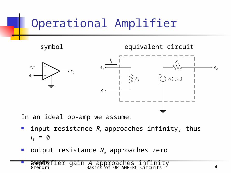
Operational Amplifier
In an ideal op-amp we assume:
input resistance Ri approaches infinity, thus i1 = 0
output resistance Ro approaches zero
amplifier gain A approaches infinity
Ri
Ro
A(e+-e-)
e+
e-
e2
i1
equivalent circuitsymbol
e+
e-e2
Stefano Gregori Basics of OP AMP-RC Circuits 5
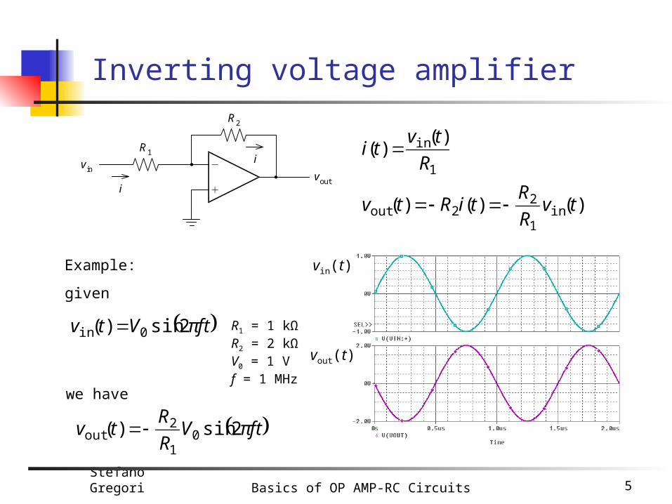
Inverting voltage amplifier
R1
R2
vinvout
i
i1
in )()(
R
tvti
)()()( in1
22out tv
R
RtiRtv
Example:
ftπVtv 2sin)( 0in
given
we have
R1 = 1 kΩR2 = 2 kΩV0 = 1 Vf = 1 MHz
ftπVR
Rtv 2sin)( 0
1
2out
vin(t)
vout(t)
Stefano Gregori Basics of OP AMP-RC Circuits 6
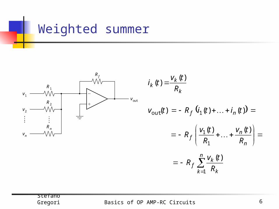
Weighted summer
k
kk R
tvti
)()(
)()( )( 1out titiRtv nf
R1
Rf
v1voutR2
v2
Rn
vn
n
k k
kf R
tvR
1
)(
n
nf R
tv
R
tvR
)()(
1
1

Stefano Gregori Basics of OP AMP-RC Circuits 7
Noninverting voltage amplifier
R1
R2
vin
vouti
i1
in )()(
R
tvti
)( 1)( )( in1
221out tv
R
RtiRRtv
Example:
ftπVtv 2sin)( 0in
given
we have
R1 = 1 kΩR2 = 1 kΩV0 = 1 Vf = 1 MHz
ftπVR
Rtv 2sin1)( 0
1
2out
vin(t)
vout(t)

Stefano Gregori Basics of OP AMP-RC Circuits 8
Buffer amplifier
vin
vout
)()( inout tvtv
Stefano Gregori Basics of OP AMP-RC Circuits 9
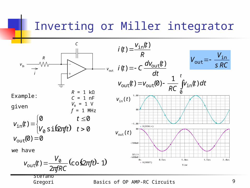
Inverting or Miller integrator
R
tvti
)()( in
)(1
)0()(0
inoutout t
dttvRC
vtv
R
C
vinvout
i dt
tdvCti
)()( out
Example:
0
0
2sin
0)(
0in
t
t
ftπVtv
0)0(out v
12cos2
)( 0out πft
fRCπ
Vtv
given
we have
vin(t)
vout(t)
R = 1 kΩC = 1 nFV0 = 1 Vf = 1 MHz
RCs
VV
in
out

Stefano Gregori Basics of OP AMP-RC Circuits 10
Inverting differentiator (1)
dt
tdvRCtRitv
)()()( in
out
dt
tdvCti
)()( in
Example:
0
0
2sin
0)(
0in
t
t
ftπVtv
given
we have
R = 1 kΩC = 100 pFV0 = 1 Vf = 1 MHz
C
R
vinvout
i
vin(t)
vout(t)
0
0
2cos2
0)(
0out
t
t
ftπfRCVπtv
Cs
inout VRCsV

Stefano Gregori Basics of OP AMP-RC Circuits 11
Inverting differentiator (2)
vout(t) is a square waveform with:- vout max 2,068 V- vout min -2,068 V- frequency 500 kHz
R = 22 kΩC = 47 pFvin(t) is a triangular waveform with:
- vin max 2 V- vin min 0 V- frequency 500 kHz
vin(t)
vout(t)
C
R
vinvout
Cs Cs

Stefano Gregori Basics of OP AMP-RC Circuits 12
Inverting lossy integrator
R1
R2
vinvout
C
in
21
out1
1V
RsCR
V

Stefano Gregori Basics of OP AMP-RC Circuits 13
Inverting weighted summing integrator
R1
v1voutR2
v2
Rn
vn
C
n
k k
kout R
V
sC V
1
1

Stefano Gregori Basics of OP AMP-RC Circuits 14
Subtractor
2
321
1031
1
0 VRRR
RRRV
R
R Vout
R1
R0
v1vout
R2
v2
R3

Stefano Gregori Basics of OP AMP-RC Circuits 15
Integrator and differentiator
integrator
differentiator
frequency behavior
R
C
vinvout
C
R
vinvout
integrator differentiator
R = 1 kΩC = 1 nF
2
1V fRCπ
A
fRCπA 2V vin(t) is a sinewave with frequency f.
Figure shows how circuit gain AV changes with the frequency f
AV is the ratio between the amplitude of the output sinewave vout(t) and the amplitude of the input sinewave vin(t)

Stefano Gregori Basics of OP AMP-RC Circuits 16
Low-pass and high-pass circuits
low-passvoutlpvin
R
C
C
vin vouthp
R
low-pass circuit
high-pass circuit
frequency behavior
high-pass
R = 1 kΩC = 1 nF
Stefano Gregori Basics of OP AMP-RC Circuits 17
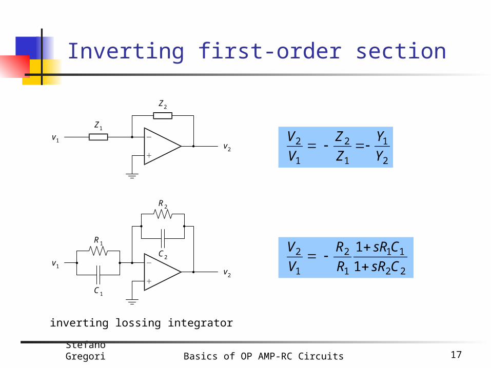
Inverting first-order section
v1v2
R1
C1
R2
C2
Z1
Z2
v1v2
2
1
1
2
1
2 Y
Y
Z
Z
V
V
1
1
22
11
1
2
1
2
CsR
CsR
R
R
V
V
inverting lossing integrator

Stefano Gregori Basics of OP AMP-RC Circuits 18
Noninverting first-order section
2
1
1
2
1
2 1 1Y
Y
Z
Z
V
V
1
11
22
11
1
2
1
2
CsR
CsR
R
R
V
V
noninverting lossing integrator
Z1
Z2
v1
v2
v1
v2
R1
C1
R2
C2
Stefano Gregori Basics of OP AMP-RC Circuits 19
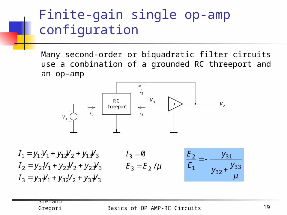
Finite-gain single op-amp configuration
V1
RCthreeport
V2
V3
i2
i3i1
Many second-order or biquadratic filter circuits use a combination of a grounded RC threeport and an op-amp
3332321313
3232221212
3132121111
VyVyVyI
VyVyVyI
VyVyVyI
μEE
I
/
0
23
3
μ
yy
y
E
E
3332
31
1
2

Stefano Gregori Basics of OP AMP-RC Circuits 20
Infinite-gain single op-amp configuration
32
31
1
2
y
y
E
E
V1
RCthreeport
V2
V3

Stefano Gregori Basics of OP AMP-RC Circuits 21
Gain reduction
V1
N
V2
Z
V1
N
V2
Z1
Z2
V1'
To reduce the gain to α times its original value (α < 1) we make
21
2
1
1
ZZ
Zα
V
V
Z
ZZ
ZZ
21
21and
solving for Z1 and Z2, we get
α
ZZ 1 Z
αZ
1
12and

Stefano Gregori Basics of OP AMP-RC Circuits 22
Gain enhancement
A simple scheme is to increase the amplifier gain and decrease the feedback of the same amount
V1
RCthreeport
V2
V3 K
1/KV2/K
μ
yy
Ky
E
E
3332
31
1
2
Stefano Gregori Basics of OP AMP-RC Circuits 23
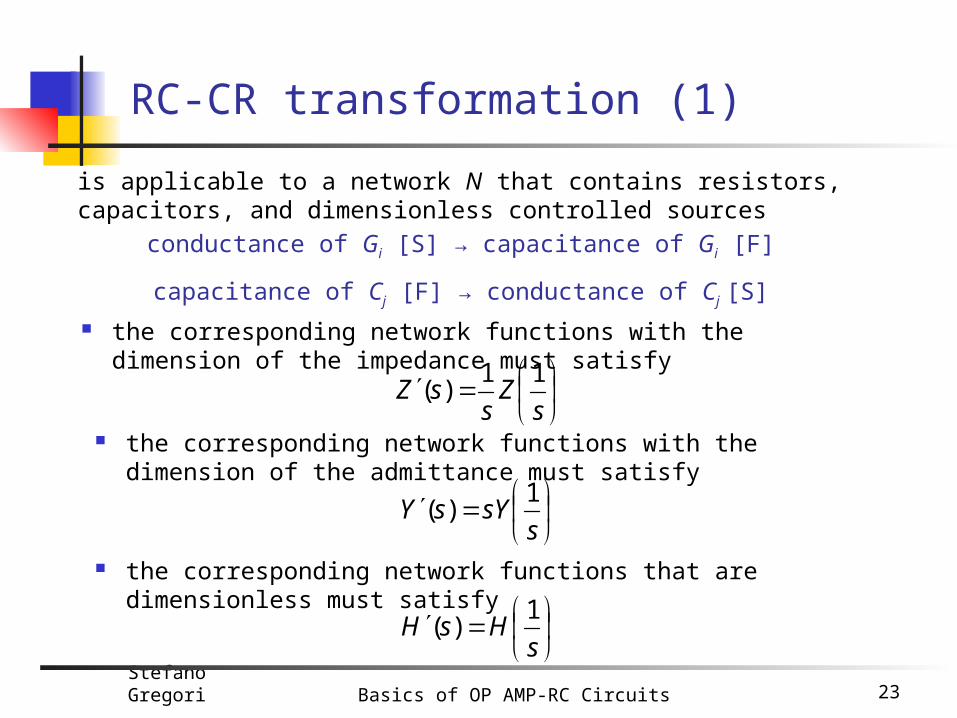
RC-CR transformation (1)
is applicable to a network N that contains resistors, capacitors, and dimensionless controlled sources
conductance of Gi [S] → capacitance of Gi [F]
capacitance of Cj [F] → conductance of Cj [S]
the corresponding network functions with the dimension of the impedance must satisfy
sZ
ssZ
11)(
the corresponding network functions with the dimension of the admittance must satisfy
ssYsY
1)(
the corresponding network functions that are dimensionless must satisfy
sHsH
1)(

Stefano Gregori Basics of OP AMP-RC Circuits 24
RC-CR transformation (2)
672
12)(
21
2
ssV
VsH
1 F
v1' v2'2
1/2 F
3
2
v1 v2
12
2
1/3 F
1/2 F
)12(
672)(
2
1
111
ss
ss
I
VsZ
276
12)(
2
2
1
2
ss
s
V
VsH
)2(
276)(
2
1
111
ss
ss
I
VsZ
N N’

Stefano Gregori Basics of OP AMP-RC Circuits 25
Sallen-Key filters
lowpass filter
highpass filter
frequency behavior
C
vin
vout
C
R
R
C
vin
vout
C
RR
lowpass highpass
bandpass
R = 1 kΩC = 1 nF

Stefano Gregori Basics of OP AMP-RC Circuits 26
2 4 6 8 10
0.2
0.4
0.6
0.8
1
2 4 6 8 10
0.2
0.4
0.6
0.8
1
2 4 6 8 10
0.2
0.4
0.6
0.8
1
2 4 6 8 10
0.2
0.4
0.6
0.8
1
2 4 6 8 10
0.2
0.4
0.6
0.8
1
Types of biquadratic filters
012
0
bsbs
Gb
012
2
bsbs
Gs
012
1
bsbs
sGb
012
02
2
bsbs
asa
01
201
2
bsbs
bsbsG
lowpass highpass bandpass bandreject allpass
Recommended