November 2011 Doc ID 2074 Rev 2 1/21
AN417Application note
From nickel-cadmium to nickel-hydride fast battery charger
1 Introduction
Today, many cordless and portable equipment are supplied by a rechargeable battery (Nickel-Cadmium, NiCd or Nickel-Hydride, NiMH). Individual applications such as portable phones, camcorders, cordless power tools, portable appliances and audio equipment highlight the enormous contribution made by rechargeable batteries to our comfortable lifestyle. NiCd battery chargers charging in one hour and even less are already widespread. Ultra fast charging of NiCd batteries in less than 15 minutes is a very attractive feature in applications where the battery is rapidly discharged, as in power tools such as cordless drills [1.].
Nevertheless, when fast charging, the use of a non-adapted charge termination method may lead to a significant reduction of the battery service life. This could cause a prejudice against the appliance manufacturer's image, as when the battery service life is reduced, the user is practically led to a costly replacement of the complete battery pack.
The trend is now to replace NiCd batteries by the more environmentally friendly NiMH batteries. Several charger applications such as notebook computers and portable phones already require NiCd /NiMH compatible battery chargers. In this case, the most common charge monitoring method used for a NiCd battery (negative delta voltage: [-Δ V]) is no longer suited to the NiMH battery.
In this application, the charge termination method is based on the detection of the inflexion point in the battery voltage curve. This inflexion point detection method is not only "NiCd-NiMH compatible", it also significantly increases the NiCd battery life-time when fast charging.
Such a high performance charger can be totally managed by a low cost 8-bit microcontroller (MCU), the ST6210. Safe charging is achieved by the combination of three back-up charge termination methods: [-Δ V] detection, temperature monitoring and timer cut-off. An additional benefit of using such a 20 pin standard microcontroller lies in its high adaptability of application features.
The proposed charging power converters use the Switched Mode Power Supply technology (SMPS), operating from AC mains or DC voltage sources. A 35W/100kHz offline and a 15W/100kHz DC/DC chargers are described in this note.
www.st.com

Contents AN417
2/21 Doc ID 2074 Rev 2
Contents
1 Introduction . . . . . . . . . . . . . . . . . . . . . . . . . . . . . . . . . . . . . . . . . . . . . . . . 1
2 Charge termination methods . . . . . . . . . . . . . . . . . . . . . . . . . . . . . . . . . . 5
2.1 The [-Δ V] method . . . . . . . . . . . . . . . . . . . . . . . . . . . . . . . . . . . . . . . . . . . 5
2.2 The inflexion point method . . . . . . . . . . . . . . . . . . . . . . . . . . . . . . . . . . . . . 7
3 Principle of the inflexion method . . . . . . . . . . . . . . . . . . . . . . . . . . . . . . . 9
4 Charge control program description . . . . . . . . . . . . . . . . . . . . . . . . . . . 10
5 Test results . . . . . . . . . . . . . . . . . . . . . . . . . . . . . . . . . . . . . . . . . . . . . . . 11
6 Charger schematic examples . . . . . . . . . . . . . . . . . . . . . . . . . . . . . . . . . 14
6.1 Block diagram . . . . . . . . . . . . . . . . . . . . . . . . . . . . . . . . . . . . . . . . . . . . . . 14
6.2 Battery charger examples . . . . . . . . . . . . . . . . . . . . . . . . . . . . . . . . . . . . 15
6.2.1 Offline charger . . . . . . . . . . . . . . . . . . . . . . . . . . . . . . . . . . . . . . . . . . . . 15
6.2.2 DC/DC charger . . . . . . . . . . . . . . . . . . . . . . . . . . . . . . . . . . . . . . . . . . . 15
7 Conclusion . . . . . . . . . . . . . . . . . . . . . . . . . . . . . . . . . . . . . . . . . . . . . . . . 18
8 References . . . . . . . . . . . . . . . . . . . . . . . . . . . . . . . . . . . . . . . . . . . . . . . . 19
9 Revision history . . . . . . . . . . . . . . . . . . . . . . . . . . . . . . . . . . . . . . . . . . . 20
AN417 List of tables
Doc ID 2074 Rev 2 3/21
List of tables
Table 1. Charge of different battery types with an 2.2 A current source. . . . . . . . . . . . . . . . . . . . . . 13Table 2. Document revision history . . . . . . . . . . . . . . . . . . . . . . . . . . . . . . . . . . . . . . . . . . . . . . . . . 20

List of figures AN417
4/21 Doc ID 2074 Rev 2
List of figures
Figure 1. Battery charger circuit diagram. . . . . . . . . . . . . . . . . . . . . . . . . . . . . . . . . . . . . . . . . . . . . . . 5Figure 2. The negative delta voltage method fast charge is terminated at point A . . . . . . . . . . . . . . . 6Figure 3. Fast charge terminates at point B in the inflexion point method . . . . . . . . . . . . . . . . . . . . . . 7Figure 4. NiMH versus NiCd charging characteristics . . . . . . . . . . . . . . . . . . . . . . . . . . . . . . . . . . . . . 8Figure 5. Inflexion point method. . . . . . . . . . . . . . . . . . . . . . . . . . . . . . . . . . . . . . . . . . . . . . . . . . . . . . 9Figure 6. Simplified program flowchart . . . . . . . . . . . . . . . . . . . . . . . . . . . . . . . . . . . . . . . . . . . . . . . 10Figure 7. Charge of a 1.4 Ah NiCd battery with the -[Δ V] method: charging current 2.2 A, total
time 48 mn, temperature increase 9.6°C. . . . . . . . . . . . . . . . . . . . . . . . . . . . . . . . . . . . . . . 11Figure 8. Charge of a 1.4 Ah NiCd battery with the inflexion method: charging current 2.2 A,
total time 41 mn, temperature increase 5°C. . . . . . . . . . . . . . . . . . . . . . . . . . . . . . . . . . . . 12Figure 9. Charge of a 2.2 Ah NiMH battery with the -[Δ V] method: charging current 2.2 A, total
time 63 mn, temperature increase 18.2°C. . . . . . . . . . . . . . . . . . . . . . . . . . . . . . . . . . . . . . 12Figure 10. Charge of a 2.2 Ah NiMH battery with the inflexion method: charging current 2.2 A,
total time 57 mn, temperature increase 7.5°C. . . . . . . . . . . . . . . . . . . . . . . . . . . . . . . . . . . 13Figure 11. Block diagram of an off-line SMPS charger . . . . . . . . . . . . . . . . . . . . . . . . . . . . . . . . . . . . 14Figure 12. Block diagram of a DC/DC charger . . . . . . . . . . . . . . . . . . . . . . . . . . . . . . . . . . . . . . . . . . 14Figure 13. This 35W/100kHz off-line charger is an asymmetrical half-bridge regulated in current
mode from its primary side . . . . . . . . . . . . . . . . . . . . . . . . . . . . . . . . . . . . . . . . . . . . . . . . . 16Figure 14. This 15W/100kHz DC-to-DC charger is also driven by a low-cost PWM control
integrated circuit, the UC3843 . . . . . . . . . . . . . . . . . . . . . . . . . . . . . . . . . . . . . . . . . . . . . . 17

AN417 Charge termination methods
Doc ID 2074 Rev 2 5/21
2 Charge termination methods
Basically, NiCd and NiMH batteries are charged by a constant current source (see Figure 1).
A battery charger is made of a constant current source controlled by a microcontroller which monitors the battery voltage variation with its internal analog-to-digital converter
Figure 1. Battery charger circuit diagram
As soon as the full capacity of the battery has been detected by the microcontroller, the charging is stopped by turning the current off. Schematic examples of power converters operating as current sources are given later. The same converter hardware can be used in two different charging methods depending upon the appliance requirements.
2.1 The [-Δ V] methodWhen a NiCd battery reaches full charge, its voltage decreases slightly (see Figure 2). The negative delta voltage method [-Δ V] consists of stopping the charge as soon as the voltage slope versus time becomes negative. This first charge termination technique is optimized to fast charge a NiCd battery to its full capacity.
micro controller
cell voltageI charge
battery
Vin
NiCd
or
NiMH
ST62xx

Charge termination methods AN417
6/21 Doc ID 2074 Rev 2
Figure 2. The negative delta voltage method fast charge is terminated at point A
In fact, a NiCd battery charged with the [-Δ V] method is slightly overcharged: Figure 2 shows that the battery temperature has substantially increased at point A when charge is terminated, which may decrease the life-time of the battery. More precisely in Figure 3, most of the current fed to the battery between point B and the negative voltage drop A is not directly converted into active battery charge, but into heat. This can be seen in the temperature curve shown in Figure 3. The point B corresponds to the inflexion point of the battery voltage curve versus time.
The [-Δ V] method is definitely no longer suited when it comes to charging NiMH batteries: the NiMH charging reaction is permanently exothermic (releases heat), so the battery temperature would become excessive in its [-Δ V] area of the voltage curve (see Figure 3).
Another characteristic of the NiMH batteries makes the [-Δ V] method unsuitable: some types of NiMH batteries do not exhibit a significant voltage drop as NiCd batteries do when reaching their full capacity.
charging time
cell voltage
battery voltage
battery temperature
temperature
1.2
1.3
1.4
1.5
1.6
20
30
40
50
60
-dV
deg CV
A

AN417 Charge termination methods
Doc ID 2074 Rev 2 7/21
2.2 The inflexion point methodA second charge termination method much more adapted to NiMH batteries consists of detecting the inflexion point of the voltage curve, thus avoiding any excessive overheating of the battery. This method therefore significantly increases the battery life-time.
Figure 3. Fast charge terminates at point B in the inflexion point method
charging time
cell voltage
battery voltage
battery temperature
temperature
1.2
1.3
1.4
1.5
1.6
20
30
40
50
60
deg CV
B
A

Charge termination methods AN417
8/21 Doc ID 2074 Rev 2
Figure 4. NiMH versus NiCd charging characteristics
Note: The NiMH battery temperature rise is larger during fast charge, and its -[Δ V] is less important, than its voltage slope variation.
Detecting the inflexion point of the voltage curve with the MCU requires the evaluation of the first derivative of the battery voltage curve versus time, and to detect its summit.
charging time
NiCd voltage
NiMH voltage
NiCd temperature
NiMH temperature
AN417 Principle of the inflexion method
Doc ID 2074 Rev 2 9/21
3 Principle of the inflexion method
Every 4 seconds, the analog to digital converter (ADC) of the ST6210 microcontroller measures the battery voltage and temperature. If the temperature is above a predetermined threshold (40 degrees Celsius for example), fast charge is terminated.
The battery voltage is actually measured several times in series, and an average of the measurements is made, to reduce measurement errors due to high frequency noise (for example generated by a switched mode charging current).
Further, a rolling average of the present and previous measurements is made, to remove low frequency noise due to electrochemical battery voltage variations (see previous description of this technique in References [1.]).
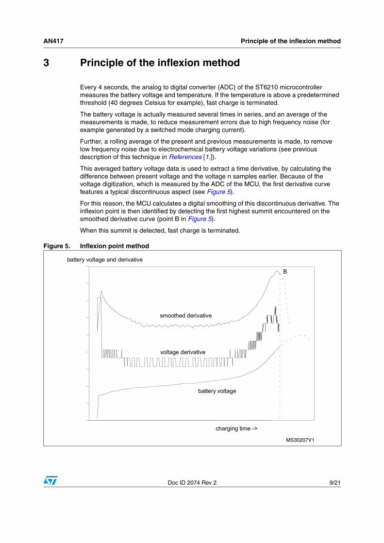
This averaged battery voltage data is used to extract a time derivative, by calculating the difference between present voltage and the voltage n samples earlier. Because of the voltage digitization, which is measured by the ADC of the MCU, the first derivative curve features a typical discontinuous aspect (see Figure 5).
For this reason, the MCU calculates a digital smoothing of this discontinuous derivative. The inflexion point is then identified by detecting the first highest summit encountered on the smoothed derivative curve (point B in Figure 5).
When this summit is detected, fast charge is terminated.
Figure 5. Inflexion point method
battery voltage
voltage derivative
smoothed derivative
charging time ->
B
battery voltage and derivative

Charge control program description AN417
10/21 Doc ID 2074 Rev 2
4 Charge control program description
The microcontroller detects the inflexion point in the battery voltage versus time curve while charging. When full charge is detected, the MCU puts the charger in trickle charge mode.
As safety protection, the MCU also terminates fast charge if -[Δ V] is detected, or the battery temperature exceeds a predetermined threshold, or a timer with programmable time duration expires.
Figure 9 shows the simplified flowchart of the program for the complete charge control. The overall system is reset after each new input source voltage connection. It is also reset when a charged battery is removed, and replaced by a discharged battery.
Figure 6. Simplified program flowchart
NEW BATTERY INSERTED ?
START
NOISE FILTERING AND AVERAGING
CALCULATE DERIVATIVE
SMOOTH DERIVATIVE
ARE WE AT INFLEXION ?
ARE WE AT DELTA-V ?
IS TIMER EXPIRED ?
WAIT 4 SECONDS
IS TEMPERATURE ABOVE THRESHOLD ?
IS BATTERY PRESENT ?
TRICKLE MODE
MEASURE BATTERY VOLTAGE 256 TIMES
Y
Y
Y
Y
N
Y
N
N
N
N
YN

AN417 Test results
Doc ID 2074 Rev 2 11/21
5 Test results
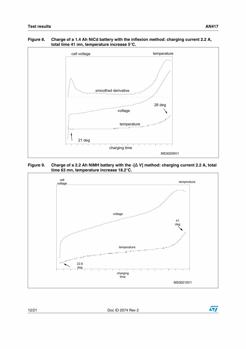
Figure 7 and Figure 8 show curves of a NiCd battery charge respectively terminated by -[Δ V] and inflexion point methods. A similar comparison is made with a NiMH battery in Figure 9 and Figure 10. The charging current is 2.2 A, the NiCd battery was a 1.4 Ah type and the NiMH battery a 2.2 Ah type. These measurement results clearly show that the battery temperature increase is much smaller with the inflexion method than with the conventional -[Δ V] method. Moreover, these curves demonstrate that a one hour charge of NiMH batteries can be properly monitored by the ST6210 MCU.
Figure 7. Charge of a 1.4 Ah NiCd battery with the -[Δ V] method: charging current 2.2 A, totaltime 48 mn, temperature increase 9.6°C.
charging time
cell voltage temperature
voltage
temperature
22.4 deg
32 deg
Test results AN417
12/21 Doc ID 2074 Rev 2
Figure 8. Charge of a 1.4 Ah NiCd battery with the inflexion method: charging current 2.2 A,total time 41 mn, temperature increase 5°C.
Figure 9. Charge of a 2.2 Ah NiMH battery with the -[Δ V] method: charging current 2.2 A, totaltime 63 mn, temperature increase 18.2°C.
charging time
cell voltage temperature
voltage
temperature
21 deg
26 deg
smoothed derivative
chargingtime
cell voltage temperature
voltage
temperature
22.8 deg
41 deg

AN417 Test results
Doc ID 2074 Rev 2 13/21
Figure 10. Charge of a 2.2 Ah NiMH battery with the inflexion method: charging current 2.2 A,total time 57 mn, temperature increase 7.5°C.
charging time
cell voltage temperature
voltage
temperature
19 deg
26.5 deg
smoothed voltage derivative
Table 1. Charge of different battery types with an 2.2 A current source
Battery Monitoring Duration Temperature increase
NiCd 1.4 Ah-[ΔV]inflexion point
48 min.41 min.
9.6 °C5 °C
NiMH 2.2 Ah-[ΔV]inflexion point
63 min.57 min.
18.2 °C7.5 °C

Charger schematic examples AN417
14/21 Doc ID 2074 Rev 2
6 Charger schematic examples
6.1 Block diagramThe charger is a power supply operating as a constant current source. Such a current source can be made with a SMPS working from the AC mains or from a DC voltage source. Figure 11 and Figure 12 give block diagrams of an offline SMPS charger and a DC to DC charger.
Figure 11. Block diagram of an off-line SMPS charger
Figure 12. Block diagram of a DC/DC charger
AC mains SMPS
MCU
ST6210
PWMcurrentmode
UC3845
NiMHor
NiCdbattery
temperature
voltage
DC voltage SMPS
MCU
ST6210
PWMcurrentmode
UC3843
NiMHor
NiCdbattery
temperature
voltage
AN417 Charger schematic examples
Doc ID 2074 Rev 2 15/21
6.2 Battery charger examples
6.2.1 Offline charger
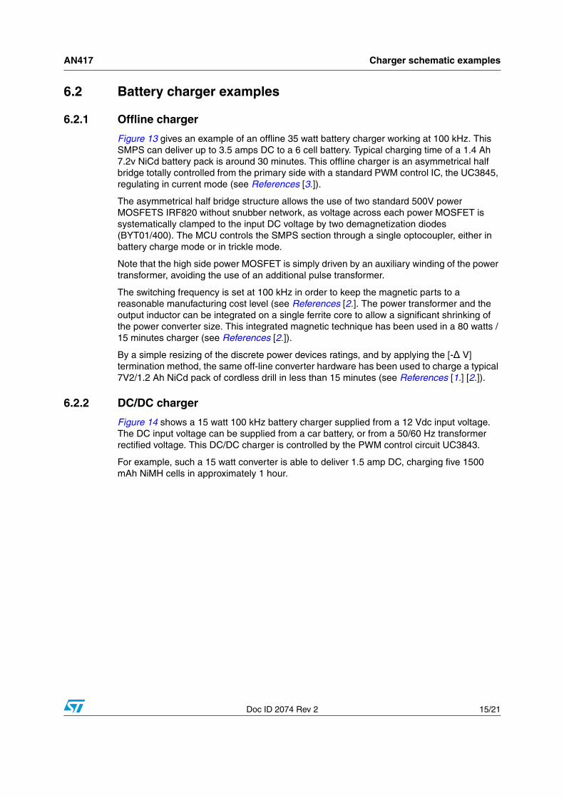
Figure 13 gives an example of an offline 35 watt battery charger working at 100 kHz. This SMPS can deliver up to 3.5 amps DC to a 6 cell battery. Typical charging time of a 1.4 Ah 7.2v NiCd battery pack is around 30 minutes. This offline charger is an asymmetrical half bridge totally controlled from the primary side with a standard PWM control IC, the UC3845, regulating in current mode (see References [3.]).
The asymmetrical half bridge structure allows the use of two standard 500V power MOSFETS IRF820 without snubber network, as voltage across each power MOSFET is systematically clamped to the input DC voltage by two demagnetization diodes (BYT01/400). The MCU controls the SMPS section through a single optocoupler, either in battery charge mode or in trickle mode.
Note that the high side power MOSFET is simply driven by an auxiliary winding of the power transformer, avoiding the use of an additional pulse transformer.
The switching frequency is set at 100 kHz in order to keep the magnetic parts to a reasonable manufacturing cost level (see References [2.]. The power transformer and the output inductor can be integrated on a single ferrite core to allow a significant shrinking of the power converter size. This integrated magnetic technique has been used in a 80 watts / 15 minutes charger (see References [2.]).
By a simple resizing of the discrete power devices ratings, and by applying the [-Δ V] termination method, the same off-line converter hardware has been used to charge a typical 7V2/1.2 Ah NiCd pack of cordless drill in less than 15 minutes (see References [1.] [2.]).
6.2.2 DC/DC charger
Figure 14 shows a 15 watt 100 kHz battery charger supplied from a 12 Vdc input voltage. The DC input voltage can be supplied from a car battery, or from a 50/60 Hz transformer rectified voltage. This DC/DC charger is controlled by the PWM control circuit UC3843.
For example, such a 15 watt converter is able to deliver 1.5 amp DC, charging five 1500 mAh NiMH cells in approximately 1 hour.

Charger schematic examples AN417
16/21 Doc ID 2074 Rev 2
Figure 13. This 35W/100kHz off-line charger is an asymmetrical half-bridge regulated in currentmode from its primary side
47uF
200V
1A 400V
10R
220
110
MA
INS
90/2
60VA
C
1A
+
47U
F20
0V
IRF8
2047
0K
270K
1/2W
1N41
48
BYT
01/4
00
4.7R
BZX
83C
18
BZX
83C
18
EF2
5
BZW
04P1
522
0uF
25V
STP
S30
45C
T70
uH/4
A
-
4N25
1.5K
680
1.8K 1K
27pF
27pF
VD
D1
TIM
ER2
OSC
IN3
OSC
OU
T4
NM
I5
VPP
/TES
6
RES
ET7
PB7
8
PB6
9
PB5
10
VSS
20
PA0
19
PA1
18
PA2
17
PA3
16
PB0
15
PB1
14
PB2
13
PB3
12
PB4
11
ST6
2E10
2MH
z1K
1KIN
G N DO
UT
78L0
5
4.7u
F10
V
BYV
10/4
0
100u
F25
V
IRF8
20
BYT
01/4
00
1.8R
VIN
7
VR
EF
8
RT/
CT
4G N D 5
C/S
EN3
CO
MP
1V
FB2
OU
T6
UC
3845
8.2K
4.7R
39K
4.7u
F25
V
BZX
85C
18V
BC
327
1nF
680p
F
220R
1N41
4810
0K
1uF
10V
10K
22K
4.7u
F10
V
5.6K
27K 7
86
54
123
TS27
1
120K
3.3K
6.8V
4.7u
F
5.6K
15K
5.6K 5.
6K
4.7u
F10
V

AN417 Charger schematic examples
Doc ID 2074 Rev 2 17/21
Figure 14. This 15W/100kHz DC-to-DC charger is also driven by a low-cost PWM controlintegrated circuit, the UC3843
BATT
ER
YPA
CK
6V
1500
mAH
+Vba
tt
100u
F25
V
+
5 3
1
7 2
64
L496
2
BYV
10-4
0BY
V10
-40
80uH
1.
5A
VIN
7
VREF
8
RT/
CT
4
G N D 5
C/S
EN
3C
OM
P1
VFB
2O
UT
6
UC
3843
10K
15K
1nF
2A
+
DC
+
GN
D
11 T
O 2
5V
-
4.7u
F10
V
220u
F25
V
22nF
12K
2.2u
F10
V
I=1.
5A
- 0.33
R1.
5W
680 O
n
4.7u
F16
V
VDD
1
TIM
ER
2
OSC
IN3
OSC
OU
T4
NM
I5
VPP
/TE
S6
RE
SET
7
PB7
8
PB6
9
PB5
10
VSS
20
PA0
19
PA1
18
PA2
17
PA3
16
PB0
15
PB1
14
PB2
13
PB3
12
PB4
11
ST62
E10
33pF
2MH
z
33pF
LED
Tem
p
Stop
15K
680
1K
15K
BZX
55C
3V3
6.8K
1K
R12
18K
27K 3 2
41
5
6
78
uA74
1
6.2K
9.1K
6.8K
2.2u
F10
V
2.2u
F10
V2.
2uF
10V
6.8K

Conclusion AN417
18/21 Doc ID 2074 Rev 2
7 Conclusion
A relevant feature dominates today's electronic appliances - true portability. In these cordless appliances, fast charging of the battery packs is often considered by the user as a significant comfort improvement. Such an improvement can be achieved with a safe and cost-effective charger concept using an off-the-shelf microcontroller, the ST6210.
Moreover, the present battery charger concept is NiCd/NiMH compatible, meeting the current trend to progressively replace the NiCd battery by the more environmentally friendly NiMH battery.
The charge termination method is based on the detection of the battery voltage inflexion point in order to avoid any excessive overheating of the battery. Such a charge technique significantly improves the battery service life, preventing the user from untimely replacing his battery pack by a costly new pack. In addition, this low cost microcontroller provides a safe charge by combining three other back-up termination methods typical of high end dedicated control circuits: [-Δ V] detection, battery temperature monitoring and timer cut-off.
The natural programmability benefit of such a microcontroller-based charger design allows the designer to easily implement additional user interface functions. For example, a "gas gauge" function indicating the remaining battery capacity to the user could be easily added to the present basic program, whilst retaining the same charger hardware structure. Finally, the major benefit of using this off-the-shelf ST6210 approach lies in the high adaptability of its application features.

AN417 References
Doc ID 2074 Rev 2 19/21
8 References
1. Ultra-fast NiCd battery charger using ST6210 Microcontroller AN433 (STMicroelectronics)
2. An ultra-fast NiCd battery charger concept 43rd International Appliance Technical Conference, May 5-6, West Lafayette, Indiana U.S.A. / L. Wuidart
3. A cost effective ultra-fast NiCd battery charger AN486 STMicroelectronics

Revision history AN417
20/21 Doc ID 2074 Rev 2
9 Revision history
Table 2. Document revision history
Date Revision Changes
01-Jan-1994 1 Initial release.
02-Nov-2011 2 Updated format and company logo.

AN417
Doc ID 2074 Rev 2 21/21
Please Read Carefully:
Information in this document is provided solely in connection with ST products. STMicroelectronics NV and its subsidiaries (“ST”) reserve theright to make changes, corrections, modifications or improvements, to this document, and the products and services described herein at anytime, without notice.
All ST products are sold pursuant to ST’s terms and conditions of sale.
Purchasers are solely responsible for the choice, selection and use of the ST products and services described herein, and ST assumes noliability whatsoever relating to the choice, selection or use of the ST products and services described herein.
No license, express or implied, by estoppel or otherwise, to any intellectual property rights is granted under this document. If any part of thisdocument refers to any third party products or services it shall not be deemed a license grant by ST for the use of such third party productsor services, or any intellectual property contained therein or considered as a warranty covering the use in any manner whatsoever of suchthird party products or services or any intellectual property contained therein.
UNLESS OTHERWISE SET FORTH IN ST’S TERMS AND CONDITIONS OF SALE ST DISCLAIMS ANY EXPRESS OR IMPLIEDWARRANTY WITH RESPECT TO THE USE AND/OR SALE OF ST PRODUCTS INCLUDING WITHOUT LIMITATION IMPLIEDWARRANTIES OF MERCHANTABILITY, FITNESS FOR A PARTICULAR PURPOSE (AND THEIR EQUIVALENTS UNDER THE LAWSOF ANY JURISDICTION), OR INFRINGEMENT OF ANY PATENT, COPYRIGHT OR OTHER INTELLECTUAL PROPERTY RIGHT.
UNLESS EXPRESSLY APPROVED IN WRITING BY TWO AUTHORIZED ST REPRESENTATIVES, ST PRODUCTS ARE NOTRECOMMENDED, AUTHORIZED OR WARRANTED FOR USE IN MILITARY, AIR CRAFT, SPACE, LIFE SAVING, OR LIFE SUSTAININGAPPLICATIONS, NOR IN PRODUCTS OR SYSTEMS WHERE FAILURE OR MALFUNCTION MAY RESULT IN PERSONAL INJURY,DEATH, OR SEVERE PROPERTY OR ENVIRONMENTAL DAMAGE. ST PRODUCTS WHICH ARE NOT SPECIFIED AS "AUTOMOTIVEGRADE" MAY ONLY BE USED IN AUTOMOTIVE APPLICATIONS AT USER’S OWN RISK.
Resale of ST products with provisions different from the statements and/or technical features set forth in this document shall immediately voidany warranty granted by ST for the ST product or service described herein and shall not create or extend in any manner whatsoever, anyliability of ST.
ST and the ST logo are trademarks or registered trademarks of ST in various countries.
Information in this document supersedes and replaces all information previously supplied.
The ST logo is a registered trademark of STMicroelectronics. All other names are the property of their respective owners.
© 2011 STMicroelectronics - All rights reserved
STMicroelectronics group of companies
Australia - Belgium - Brazil - Canada - China - Czech Republic - Finland - France - Germany - Hong Kong - India - Israel - Italy - Japan - Malaysia - Malta - Morocco - Philippines - Singapore - Spain - Sweden - Switzerland - United Kingdom - United States of America
www.st.com
Recommended