ReportTechnologyMasterclass‐MartijnJansen
AnOpticalMouseSensorasanextensionforLEGONXT
S030887

Index:
1.Introduction
2.SensorChoice
3.Hackingtheopticalmouse
4.HackingLEGONXT
5.Implementation
6.PossibleApplications
7.References
8.Appendix

1.IntroductionAssignmentDescriptionThisprojectispartoftheTechnologyMasterclassofIndustrialDesignattheTechnicalUniversityEindhoven.Duringthisclass,Masterstudentsgettheopportunitytodiveintosomeverydiverseelementsoftechnologylikeelectronics,mechanics,programmingintelligentrobotsandcreatinganewinnovativesensorforLEGONXT.Thisreportdescribestheelaborationofthelatterassignment.Deliverables
• workingmodeloftheextensionpack• reportinMSWorddescribingtheextensionpack• technicaldocumentationoftheextensionpack,suchastechnicaldrawingsandUMLmodels• photosoftheextensionpack• movieoftheextensionpackinactionuploadedinhighqualitytoSurfMediaandavailablefor
downloadfromthere.

2.SensorChoiceForarobotthatisabletomoveitself,itisessentialtoknowinwhatenvironmentitisandwhereinthatenvironmentitislocated.Location,distanceandspeedarevariablesthatcanhelparobotdetermineit’scurrentstate.AGPS‐sensorisabletogivethesevariables,butarequiteexpensiveandnotasaccurateasyoumightneed.Acomputermouseismoreaccurateandcandetectmovementsmallerthanamillimeter.ForthisreasonIdecidedtolookatcomputermiceasanewsensorforLEGONXT.An‘old’computermouse(fig.1)detectsmovementmechanicallythroughaballinsidethatcanrotateinanydirection.Therearethreewheelsinsidethatarepositionedagainsttheball,sothatthewheelsareturningwhentheballrolls.Thesewheelschoplightbeamsinfrontoflightsensorssoamovement,speedofmovementanddirectioncanbedetected.Thiskindofmouseisalsocalledaballmouse.
Fig.1:Aballmouse1
Adifferentkindofcomputermouseistheopticalmouse(fig.2).Theopticalmousehasasensorinsidethatisactuallyaverysmallcamera.Itdetectschangesinpicturesofthesurfaceunderneathit.ThisisthenconvertedtoanamountofmovementintotheX‐orY‐direction.AredLEDilluminatesthesurfacetoincreasethecontrastofthepictures.
fig.2:Myopticalmouse(beforethisproject)
Ichosetogofurtherwiththeopticalmousesensorforthefollowingreasons:
‐ ithasnomechanicalpartsthatcanbreakorwearoff;‐ itcanbeusedonmoresurfacesthantheballmouse;‐ aballmousecollectsdebrisinsidethecasing‐ it’squitesmall(smallerthantheballmouse);‐ it’scheap;‐ Iseealotoflearningopportunitieshere.
ThefollowingchapterswilldescribehowtocreateanopticalmousesensorfortheNXTfromacheapopticalmouse.

3.HackingtheopticalmouseIhaveusedsometutorialsIfoundoninternet2,3.Myapproachwasquitesimilar,buteventuallyIneedtoreadthedatawiththeLEGONXT.MyfirststepistohackthemousereadthedatafromthesensorwithArduino4.
TutorialforhackingtheopticalmouseThistutorialwillexplainwhatstepsyouneedtotaketohacktheopticalmouseandreadthedatawithArduino.Firsttakeanoldopticalmouseorbuyacheapone.Fig.2showshowmymouselookedlike.
1.OpenupthemouseUnderneaththemousethere’sascrewyouneedtounbolt.Thiswillopenupthemouse.Hereyoufindthecircuitboardwiththesensor(thechipinthemiddle),aLED,buttonsandthescrollwheel(fig.3).Underneaththecircuitboardisthelensclip(fig.4),thatisusedtoamplifythelightandfunctionsasalensforthesensor.
fig.3:Mouseopenedup
fig.4:lensclip
2.LookupthedatasheetThesensorislocatedinthemiddleofthecircuitboard.Searchforthedatasheetofthesensorontheinternetandlookupthepinconnections.Youneedthefollowingpins:
• +5V(inputvoltage)• GND(ground)• SCK(serialportclock)• SDIO(serialportdata)
InthecaseofmysensorIneedpin3,4,6and7(fig.5)

fig.5mechanicaldrawing+pinouttableofthedatasheet5
Makesurethatyoursensordoesn’thavetheUSB‐controllerembeddedinsidethechip.ThefirstmouseItriedtoopenhadthiskindofchip(seefig.6),whichmeansthatyoucan’tcapturethedatawithoutaUSB‐protocol.Usinga2‐wireserialportcommunicationismuchmorepreferable.
fig.6:amousewiththeUSBcontrollerembeddedinthechipofthesensor
3.SolderwiresSolderwirestothe4neededpins.It’susefultochoosedifferentcolors,soyou’reabletodistinguishtheclockanddatalineseasily(fig.7).
fig.7‐Wiressolderedtopins3,4,6and7
4.RemovetheUSB‐controllerThisstepisnotnecessary,butifyou’renotgoingtousethemouseanymoreitmightbebettertoremovetheUSB‐controllertopreventthecontrolleroftakingoverthedataconnection.Removingthecontrollercanbedonebyremovingthesolderedtinandscrapethecontrollerofthecircuitboard.5.ConnectittoArduinoChoosetwodigitalpinsontheArduinofortheclocklineandthedatalineandconnectthe+5VandGNDofthemousetothe5VandGndofArduino.Uploadthesketches(programsforArduino)providedbyMartijnThébasedonsketchesofBenoîtRousseau.MakesurethattherightregistersIfyouopentheSerialmonitorintheArduinosoftwareyou’llseethex‐andy‐values.InthenextparagraphI’llexplainhowthisworks.

GetthedatafromtheopticalmousetoArduinoInthedatasheetofthesensorthereisawholesectionaboutthesynchronousserialport.Thisportisusedtosetandreadparametersfromthesensor.Theportusestwowiresandisahalfduplexport,whichmeansthatitcantalkbothways,butnotatthesametime.Themicrocontroller,inmycasetheArduino,alwaysinitiatescommunicationandiscalledthemaster(thesensoristheslave).Thetwowiresaretheserialportclock(SCK)andthedataline(SDIO).Theserialportclockisgeneratedbythemicrocontroller.ThemicrocontrollercantrytoreadparametersliketheX‐andY‐movement,butcanalsowritetothesensortochangeparameterslikeforexampletheconfigurationofthesensor.Forthisweneedareadandawriteoperation.Theclocklineisgeneratedbythemicrocontrollerandispreferablypulsingatalengthof250nsperpulse.Thefunctionoftheclockistosynchronizedatatransfers.WriteoperationAwriteoperationisinitiatedbythemicrocontrollerandconsistsoftwobytes.Thefirstbytecontainsa7‐bitaddressandhasa“1”asitsmostsignificantbit(MSB).This1meansthatthemicrocontrollerwantstowritedataandtheaddressisaregisterwhereyouwanttowriteto.Thesecondbytecontainsthedatayouwanttowrite.Theclocksynchronizesthedatatransfer,becausethemicrocontrollerchangesSDIOonfallingedgesoftheclockandthesensorreadsSDIOonrisingedgesoftheclock.
fig.8:Writeoperation
ReadOperationAwriteoperationworkskindofthesame;italsoconsistsoftwobytes.Thefirstbytehasa“0”asMSB(toindicateareadoperation)andasevenbitaddresstorequestthedatafromacertainregister.Thesecondbyteisthedatasendfromthesensortothemicrocontroller.Afterthelastbitoftheaddressthereisadelayof100usforthesensortopreparethedata.
fig.9:ReadOperation
RegistersInthedatasheetthereisalistofaddresses(fig.10).Fromaddress0x42and0x43youcangettheDelta_YandDelta_X(X‐andY‐movement).Letmegiveanexample:IfIwanttoreadtheYmovementIhavetoperformareadoperation.Thefirstbytethemicrocontrollersendsis0x42,butwitha“0”asMSBbit.Inbit‐formthislookslikethis:”01000010”.Thenthereisadelayof100microsecondsandafterthatthesensorwillgiveabytecontainingthemovementofthesensorintheYdirection.
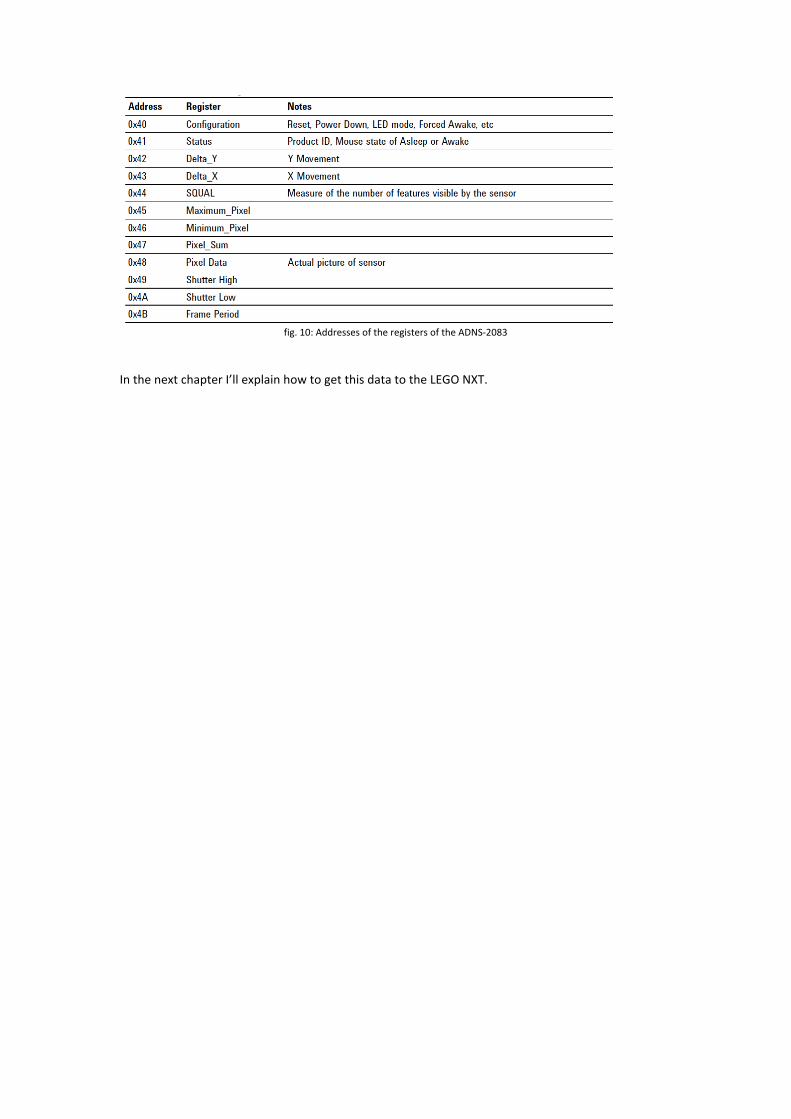
fig.10:AddressesoftheregistersoftheADNS‐2083
InthenextchapterI’llexplainhowtogetthisdatatotheLEGONXT.
4.HackingLEGONXTTheNXTisactuallyamicrocontrollerlikeArduino.ForthisassignmentweneedtoprogramtheNXTwithleJOS,aJAVA‐basedlanguagefortheNXT.Icouldn’tfigureouthowtoreadthesensordirectlywiththeNXTusingleJOS.ThereforeIchosetotoreaddatafromthesensorwithArduinoandlettheNXTcommunicatewiththeArduino.
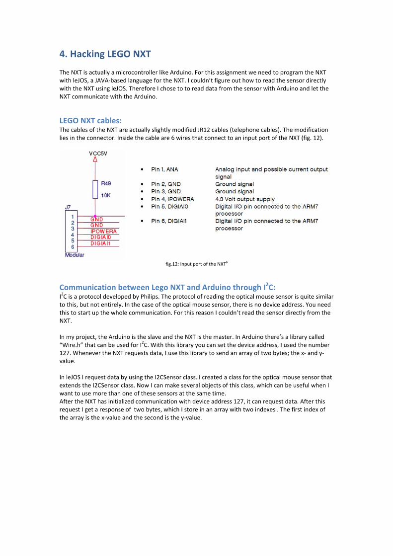
LEGONXTcables:ThecablesoftheNXTareactuallyslightlymodifiedJR12cables(telephonecables).Themodificationliesintheconnector.Insidethecableare6wiresthatconnecttoaninputportoftheNXT(fig.12).
fig.12:InputportoftheNXT6
CommunicationbetweenLegoNXTandArduinothroughI2C:I2CisaprotocoldevelopedbyPhilips.Theprotocolofreadingtheopticalmousesensorisquitesimilartothis,butnotentirely.Inthecaseoftheopticalmousesensor,thereisnodeviceaddress.Youneedthistostartupthewholecommunication.ForthisreasonIcouldn’treadthesensordirectlyfromtheNXT.Inmyproject,theArduinoistheslaveandtheNXTisthemaster.InArduinothere’salibrarycalled“Wire.h”thatcanbeusedforI2C.Withthislibraryyoucansetthedeviceaddress,Iusedthenumber127.WhenevertheNXTrequestsdata,Iusethislibrarytosendanarrayoftwobytes;thex‐andy‐value.InleJOSIrequestdatabyusingtheI2CSensorclass.IcreatedaclassfortheopticalmousesensorthatextendstheI2CSensorclass.NowIcanmakeseveralobjectsofthisclass,whichcanbeusefulwhenIwanttousemorethanoneofthesesensorsatthesametime.AftertheNXThasinitializedcommunicationwithdeviceaddress127,itcanrequestdata.AfterthisrequestIgetaresponseoftwobytes,whichIstoreinanarraywithtwoindexes.Thefirstindexofthearrayisthex‐valueandthesecondisthey‐value.
5.ImplementationThischapterdescribestheimplementationintoaworkingprototype.
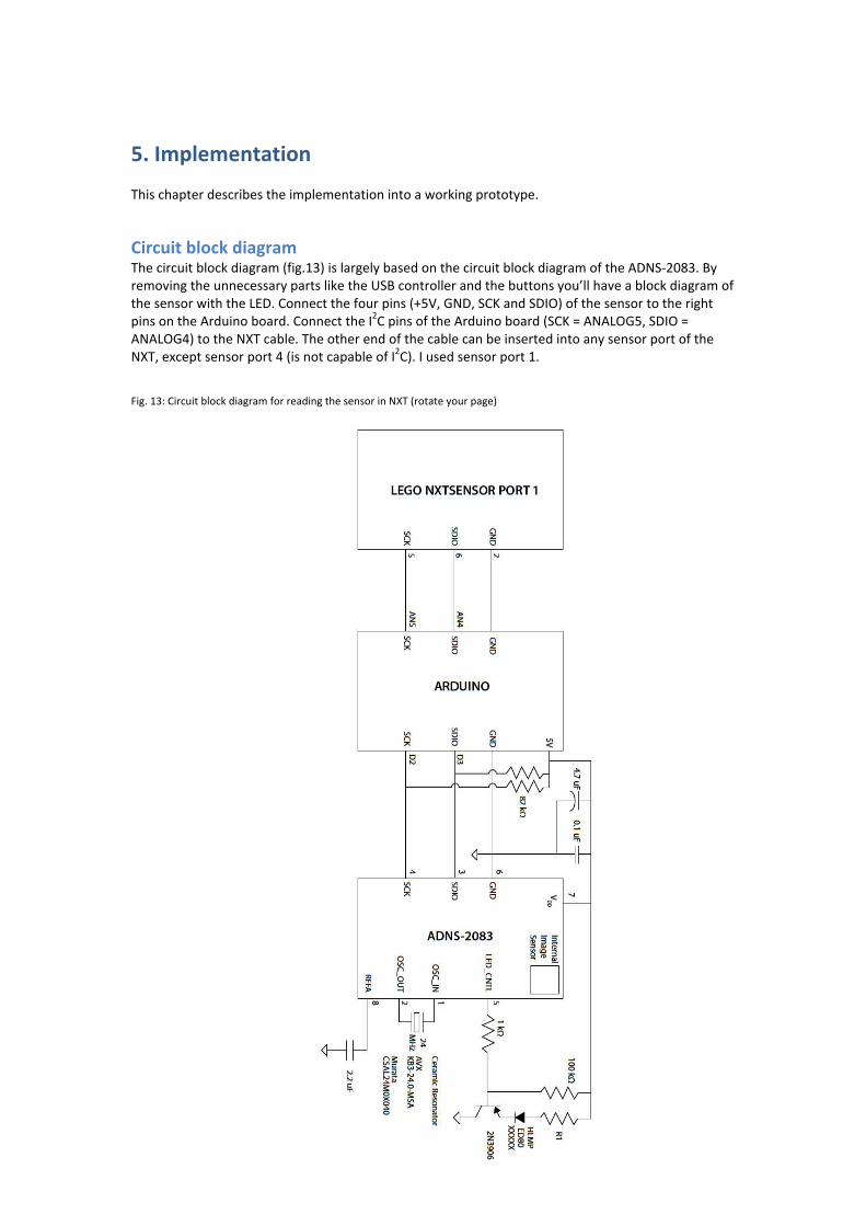
CircuitblockdiagramThecircuitblockdiagram(fig.13)islargelybasedonthecircuitblockdiagramoftheADNS‐2083.ByremovingtheunnecessarypartsliketheUSBcontrollerandthebuttonsyou’llhaveablockdiagramofthesensorwiththeLED.Connectthefourpins(+5V,GND,SCKandSDIO)ofthesensortotherightpinsontheArduinoboard.ConnecttheI2CpinsoftheArduinoboard(SCK=ANALOG5,SDIO=ANALOG4)totheNXTcable.TheotherendofthecablecanbeinsertedintoanysensorportoftheNXT,exceptsensorport4(isnotcapableofI2C).Iusedsensorport1.
Fig.13:CircuitblockdiagramforreadingthesensorinNXT(rotateyourpage)
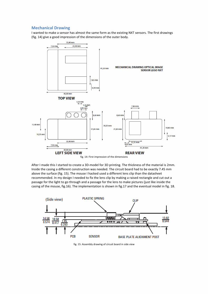
MechanicalDrawingIwantedtomakeasensorhasalmostthesameformastheexistingNXTsensors.Thefirstdrawings(fig.14)giveagoodimpressionofthedimensionsoftheouterbody.
fig.14:Firstimpressionofthedimensions
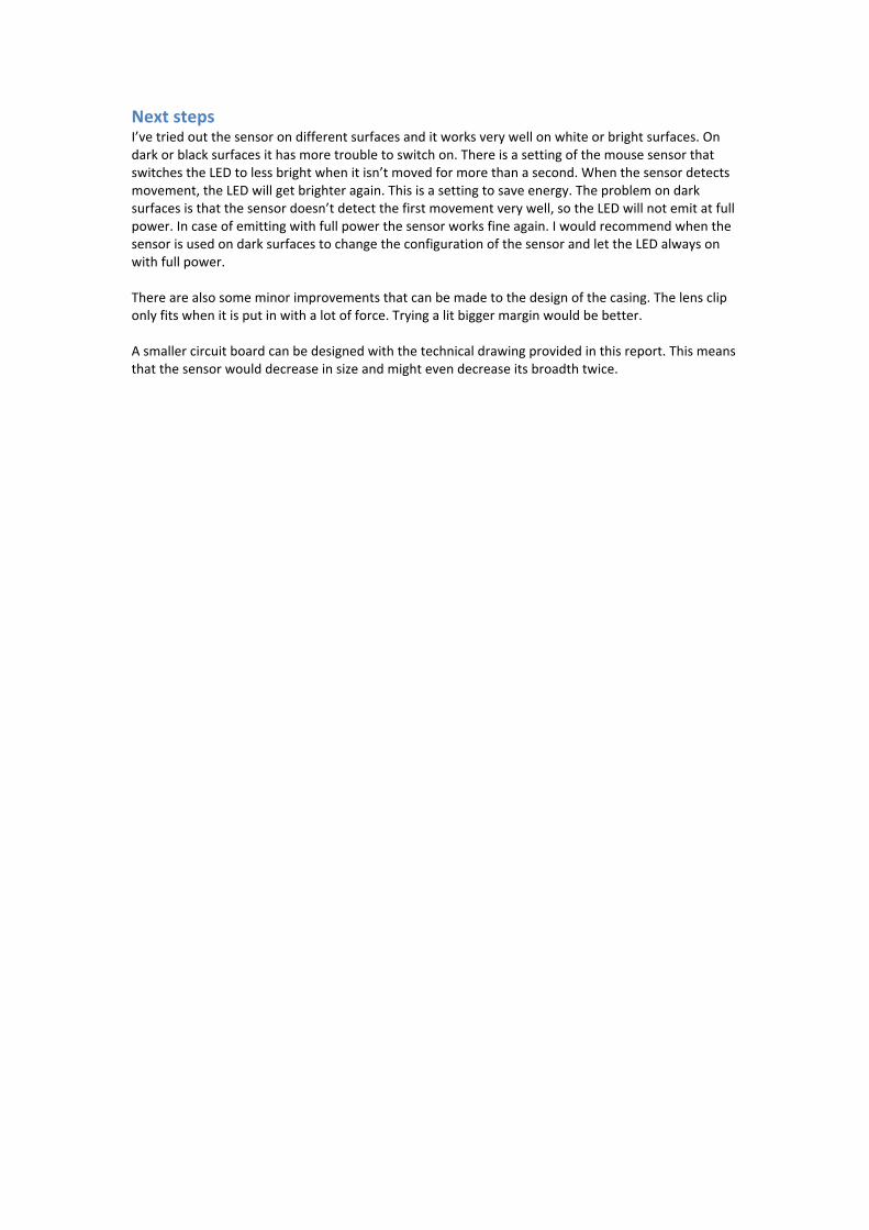
AfterImadethisIstartedtocreatea3D‐modelfor3Dprinting.Thethicknessofthematerialis2mm.Insidethecasingadifferentconstructionwasneeded.Thecircuitboardhadtobeexactly7.45mmabovethesurface(fig.15).ThemouseIhackedusedadifferentlensclipthanthedatasheetrecommended.InmydesignIneededtofixthelensclipbymakingaraisedrectangleandcutoutapassageforthelighttogothroughandapassageforthelenstomakepictures(justlikeinsidethecasingofthemouse,fig.16).Theimplementationisshowninfig.17andtheeventualmodelinfig.18.
fig.15:Assemblydrawingofcircuitboardinsideview

fig.16:Lensclipholderinthemousecasing
fig.17:Twoscreenshotsofthe3D‐CADmodelmadeinSolidWorks
fig.18:Theprototype3D‐printedwiththetechnologyinside
NextstepsI’vetriedoutthesensorondifferentsurfacesanditworksverywellonwhiteorbrightsurfaces.Ondarkorblacksurfacesithasmoretroubletoswitchon.ThereisasettingofthemousesensorthatswitchestheLEDtolessbrightwhenitisn’tmovedformorethanasecond.Whenthesensordetectsmovement,theLEDwillgetbrighteragain.Thisisasettingtosaveenergy.Theproblemondarksurfacesisthatthesensordoesn’tdetectthefirstmovementverywell,sotheLEDwillnotemitatfullpower.Incaseofemittingwithfullpowerthesensorworksfineagain.IwouldrecommendwhenthesensorisusedondarksurfacestochangetheconfigurationofthesensorandlettheLEDalwaysonwithfullpower.Therearealsosomeminorimprovementsthatcanbemadetothedesignofthecasing.Thelenscliponlyfitswhenitisputinwithalotofforce.Tryingalitbiggermarginwouldbebetter.Asmallercircuitboardcanbedesignedwiththetechnicaldrawingprovidedinthisreport.Thismeansthatthesensorwoulddecreaseinsizeandmightevendecreaseitsbroadthtwice.
6.PossibleApplicationsSomeexamplesofapplicationsusingtheNXTopticalmousesensorare:MeasuremovementArobotcanmeasurehowfarithasdrivenyet.MeasurevelocityForrobotsthathavetogowithacertainspeedyoucandividethemovementwiththetimeandyougetvelocityFeedbackloopfordrivingstraightBecausethesensormeasuresXandYvaluesitcanalsogivefeedbackaboutmovementsideways.Thisisunwantedforexamplebecauseonmotorisstrongerthantheother.Becauseyoudetectthemovementsidewaysyoucanfeedthisinformationbacktothemotors(justlikethepotentiometerinaservomotor).DrivingtocoordinatesArobotcandrivetoanexactpointintheenvironment,whenitkeepstrackofthemovementsofarandthebendsithasmade.

7.References
1. Picturefrom:http://upload.wikimedia.org/wikipedia/commons/2/2c/Ball_Mouse_semi‐inside_view.jpg
2. http://www.gurulib.com/_project/optical_mouse_hack_files/optical_mouse_hack.htm3. http://www.martijnthe.nl/optimouse/4. http://www.arduino.cc/5. DatasheetADNS‐2083(SDNS‐2083)fromAvagotechnologies6. LegoMindstormsNXTHardwareDelopmentKit

8.Appendix
A.DatasheetADNS‐2083
B.LegoMindstormsNXTHardwareDelopmentKit
C.ArduinoSketch
D.leJOSclasses
E.Videooftheworkingprototype
BecauseAppendixC&Dcontaintoomanypagestoprintandaremoreusefultohavedigital,Ihavemadethemavailableonline.AppendixEisavideoandcanbedownloaded.
C.http://www.kansloosdesign.nl/portfolio/wp‐content/uploads/2008/12/coordinates_in_mm_i2c.zip
D.http://www.kansloosdesign.nl/portfolio/wp‐content/uploads/2008/12/lejos‐optical‐mouse‐sensor.zip
E.http://www.kansloosdesign.nl/portfolio/wp‐content/uploads/2008/12/filmpje.m4v
Recommended