Monroe Shumate 6/05
Flame Propagation Capability Analysis:
Alternative Small Scale Test
for Unfaced Microlite AA® Blankets

Purpose of Study
• Confirm/verify unfaced Microlite AA glass blankets comply with FAA flame propagation requirements
• Determine product capability
InstallInsulation
Test After Test
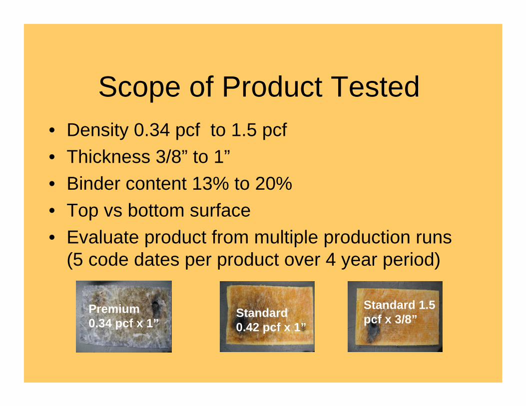
Scope of Product Tested• Density 0.34 pcf to 1.5 pcf• Thickness 3/8” to 1”• Binder content 13% to 20%• Top vs bottom surface• Evaluate product from multiple production runs
(5 code dates per product over 4 year period)
Premium 0.34 pcf x 1”
Standard 0.42 pcf x 1”
Standard 1.5 pcf x 3/8”
Test results
• Flame Propagation No failures• After Flame No failures
Test equipment – FAA test rig (gas & electric)
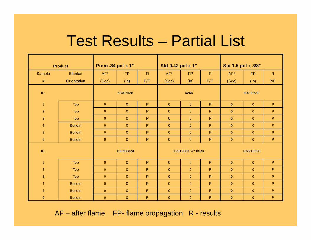
Test Results – Partial List
P00P00P00Bottom6
P00P00P00Bottom5
P00P00P00Bottom4
P00P00P00Top3
P00P00P00Top2
P00P00P00Top1
10221232312212223 ½” thick102202323ID.
P00P00P00Bottom6
P00P00P00Bottom5
P00P00P00Bottom4
P00P00P00Top3
P00P00P00Top2
P00P00P00Top1
90203630624680402636ID.
P/F(In)(Sec)P/F(In)(Sec)P/F(In)(Sec)Orientation#
RFPAF*RFPAF*RFPAF*BlanketSample
Std 1.5 pcf x 3/8"Std 0.42 pcf x 1"Prem .34 pcf x 1"Product
AF – after flame FP- flame propagation R - results
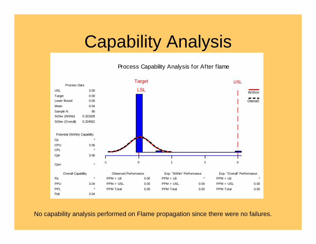
Capability Analysis
3210-1
Target USLLB
Process Capability Analysis for After f lame
PPM Total
PPM > USLPPM < LB
PPM Total
PPM > USLPPM < LB
PPM Total
PPM > USLPPM < LB
PpkPPL
PPUPp
Cpm
Cpk
CPLCPUCp
StDev (Overall)
StDev (Within)Sample NMean
Lower BoundTarget
USL
0.00
0.00 *
0.00
0.00 *
0.00
0.000.00
3.04 *
3.04 *
*
3.06
*3.06 *
0.324552
0.32192890
0.04
0.000.00
3.00
Exp. "Overall" PerformanceExp. "Within" PerformanceObserved PerformanceOverall Capability
Potential (Within) Capability
Process Data
Within
Overall
No capability analysis performed on Flame propagation since there were no failures.
Target
LSL

Development small scale test(In process test method for plain fiber glass)
• Simple/quick QA check • Simple design/operation• Short test cycle• Quick start-up
ReproducibleCorrelation to FAA test
Methodology• Multi-factorial DOE to generate samples with flame
propagation or after flame• Establish product standards utilizing FAA test rig• Design and build small scale radiant panel• Develop & verify test parameters
– Establish robust test setting– Conduct Gage R&R (Reproducibility &
Repeatability)
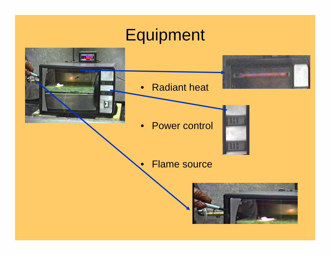
Equipment
• Radiant heat
• Power control
• Flame source
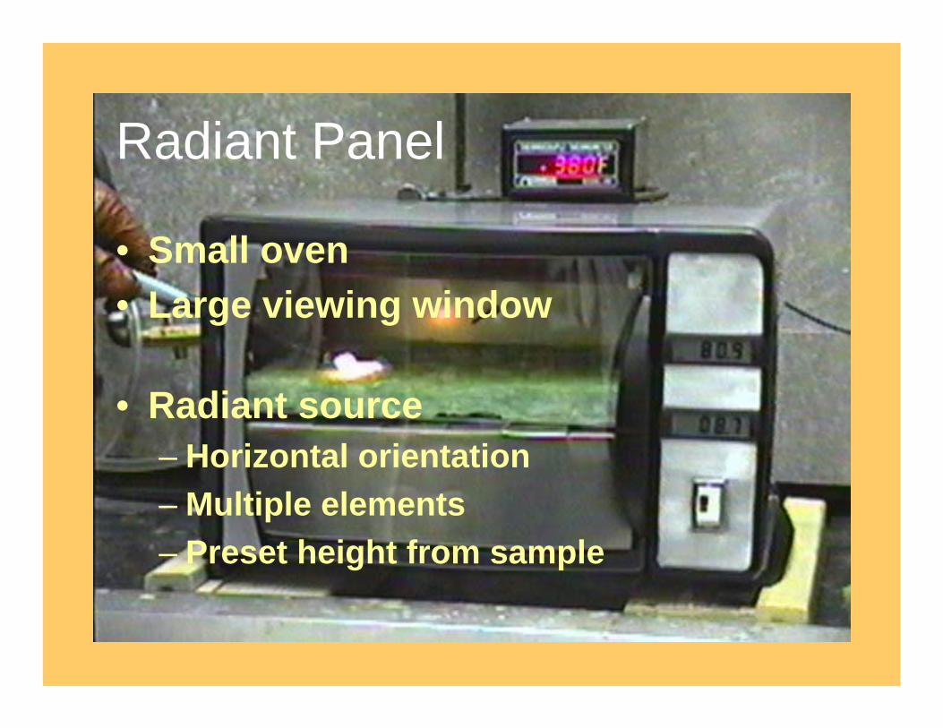
Radiant Panel
• Small oven• Large viewing window
• Radiant source– Horizontal orientation– Multiple elements– Preset height from sample

Power Control
• Heat flux controlConstant powerVariable voltage regulatorPreset input - (voltage/amp)
• Temperature measurementType “K” thermocouple
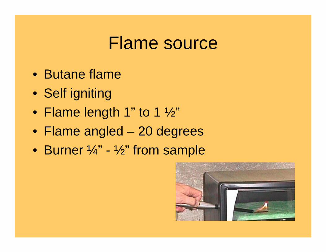
Flame source• Butane flame• Self igniting• Flame length 1” to 1 ½”• Flame angled – 20 degrees• Burner ¼” - ½” from sample

Multi-Factorial Design
A 1, 2, 3 A1
B 1, 2 B1 B2
C 1,2 C1 C2 C1 C2
Multi-factorial DOE design Produce samples to show
flame propagation or after flame
• Design layout - 3 factor – multi-variable• Conduct plant trial to produce samples• Evaluate samples at FAA
Identify which samples show flame propagation and/or after flame

FAA Radiant Panel tests(Electric Panel)
• Evaluate samples from DOE• Check for Flame propagation• Check for After flame
Results:• One sample showed Flame propagation• No samples showed After flame
No flame propagation 47 samples from DOE
1 sample from DOE showed
flame propagation
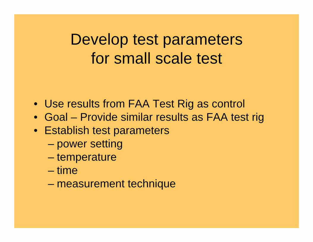
Develop test parameters for small scale test
• Use results from FAA Test Rig as control• Goal – Provide similar results as FAA test rig• Establish test parameters
– power setting– temperature– time– measurement technique

Robust test setting• Flame Propagation –
Parameters provide similar results to FAA tests:– Power settings - voltage &
amperage– Temperature (Start Temp 385F)– Flame length (1 “to 1 1/2”)– Test time (7-10 seconds)
• After Flame– No after flame was observed– Results same as FAA
Ignition Ignition
No Propagation Propagation
Pass Fail
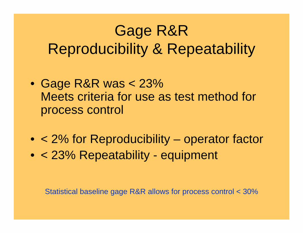
Gage R&RReproducibility & Repeatability
• Gage R&R was < 23%Meets criteria for use as test method for process control
• < 2% for Reproducibility – operator factor• < 23% Repeatability - equipment
Statistical baseline gage R&R allows for process control < 30%
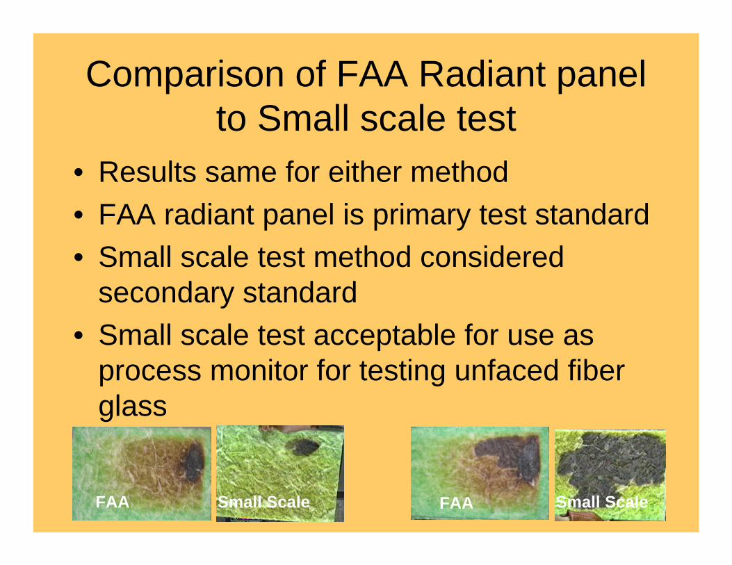
Comparison of FAA Radiant panel to Small scale test
• Results same for either method• FAA radiant panel is primary test standard• Small scale test method considered
secondary standard• Small scale test acceptable for use as
process monitor for testing unfaced fiber glass
FAA FAASmall Scale Small Scale

Recap
• Capability analysis <1 chance in a million for Microlite AA failure for after flame or flame propagation (for product tested using FAA radiant panel)
• JM continue to certify to FAR 25.853 Appendix F part I standard for flame spread and punking (standard used for all product tested for study)
• JM implement use of small scale radiant test panel as part of quality assurance program
• Test Report E436-T-03973 Available for Review ([email protected])
Monroe Shumate 6/05
Recommended


![Manual Microlite 3 13[1]](https://img.dokumen.tips/doc/110x75/5695d09e1a28ab9b029330ca/manual-microlite-3-131.jpg)
