Alcatel 5620 SAMService Aware Manager | Release 2.0
G E N E R A L I N F O R M A T I O N


Alcatel 5620 SAMService Aware Manager | Release 2.0
G E N E R A L I N F O R M A T I O N

Alcatel assumes no responsibility for the accuracy of the information presented, which is subject to change without notice.
Alcatel, the Alcatel logo, MainStreet, TiMetra, and Newbridge are registered trademarks of Alcatel. All other trademarks are the property of their respective owners.
Copyright 2004 Alcatel.
Disclaimers
Alcatel products are intended for commercial uses. Without the appropriate network design engineering, they must not be sold, licensed or otherwise distributed for use in any hazardous environments requiring fail-safe performance, such as in the operation of nuclear facilities, aircraft navigation or communication systems, air traffic control, direct life-support machines, or weapons systems, in which the failure of products could lead directly to death, personal injury, or severe physical or environmental damage. The customer hereby agrees that the use, sale, licence or other distribution of the products for any such application without the prior written consent of Alcatel, shall be at the customer's sole risk. The customer hereby agrees to defend and hold Alcatel harmless from any claims for loss, cost, damage, expense or liability that may arise out of or in connection with the use, sale, licence or other distribution of the products in such applications.
This document may contain information regarding the use and installation of non-Alcatel products. Please note that this information is provided as a courtesy to assist you. While Alcatel tries to ensure that this information accurately reflects information provided by the supplier, please refer to the materials provided with any non-Alcatel product and contact the supplier for confirmation. Alcatel assumes no responsibility or liability for incorrect or incomplete information provided about non-Alcatel products.
However, this does not constitute a representation or warranty. The warranties provided for Alcatel products, if any, are set forth in contractual documentation entered into by Alcatel and its customers.
This document was originally written in English. If there is any conflict or inconsistency between the English version and any other version of a document, the English version shall prevail.
PRINTED ONRECYCLED PAPER

Preface
Alcatel recognizes that today’s world-class service providers and its customers require excellence in service delivery. In today’s IP world, routers must deliver better than best-effort Internet access and must provide customer assurance tools that exceed those developed for enterprise networks.
As the world’s networks migrate towards a business-oriented, service-enabled MPLS core, Alcatel can ease the migration by combining its carrier-class networking experience with solutions that:
• help add new points of presence while protecting legacy investments as networks are migrated to IP
• provide a unified approach to services introduction with a focus on customer service satisfaction
• optimize service delivery using integrated management solutions to deliver the services your customers will value
The Alcatel 5620 Service Aware Manager (5620 SAM) software applications provide an integrated management solution. The 5620 SAM manages the nodes that deliver cutting edge Layer 2 and Layer 3 services, and gives you the network management platform tools to economically manage your OPEX and CAPEX while quickly enabling revenue-generating services.
iii

Preface
In today’s competitive business environment, customers are demanding an expanded range of service offerings. Customers also want improved SLAs, faster diagnoses of problems with their services, and a range of flexible, accurate billing options.
This presents a key challenge to service providers, as they tightly integrate network equipment management with flexible, powerful network and element management systems. Service providers that meet this challenge can offer new services to their customers while improving operational efficiency. This advantage allows you to attract and retain customers on a large scale.
The Alcatel 5620 SAM provides integrated FCAPS functionality combined with a service-oriented architecture that enables:
• superior OAM troubleshooting tools to pre-test services, manage faults, and provide quick responses to customer inquiries
• rapid service activation to start your customers’ traffic flowing
• template-based policy management to pinpoint QoS and traffic flow controls• easy-to-use GUI management tools for operators to reduce OPEX• flexible management solutions for small networks with a limited hardware
footprint to large networks with multi-technology, multi-service deployments
• reliable and growth-oriented choice of platforms, including complementary OSS integration into multivendor networks
How the 5620 SAM implements these key functions is described in the following chapters.
• Chapter 1—IP innovation: Services management• Chapter 2—Reliable platforms for growth
• Chapter 3—Selling and managing customer services• Chapter 5—Networking made easy• Chapter 4—Managing network CAPEX and OPEX
• Chapter 6—Integrated fault management and OAM• Chapter 7—Securing your IP network edge• Chapter 8—Open interfaces and OSS integration
• Appendix A—Standards compliance• Appendix B—Associated documents
iv

Contents
1 IP innovation: Services management .................................... 1
What is service routing ........................................................................... 1What is the 5620 SAM............................................................................. 3Ease of service configuration................................................................. 4What are the 7750 SR and 7450 ESS .................................................... 7Internet Enhanced Service (IES).......................................................... 7IP Virtual Private Network (IP VPN) .................................................... 9Virtual Leased Line (VLL)....................................................................10Virtual Private LAN Service (VPLS) ...................................................12
2 Reliable platforms for growth............................................. 15
Management architecture ....................................................................15Supported deployment sizes................................................................18
3 Selling and managing customer services ............................ 19
Creating services made easy................................................................20Service location and subscriber management....................................22
v

Contents
Policies and QoS....................................................................................23Accounting and performance monitoring using statistics ................30
4 Networking made easy ..................................................... 33
Routing protocol and signaling support and implementation ..........33MPLS and LSPs .....................................................................................38
5 Managing network CAPEX and OPEX................................. 41
Implementation of functionality ..........................................................41Configuration management..................................................................42Viewing and managing inventories......................................................47Topology management..........................................................................48Resynchronization with network elements ........................................50End-to-end, integrated management solutions .................................50
6 Integrated fault management and OAM ............................. 53
Intelligent alarm fault management ....................................................54Service assurance with diagnostics .....................................................56
7 Securing your IP network edge .......................................... 61
Security end-to-end ..............................................................................61
8 Open interfaces and OSS integration ................................. 65
Open interfaces .....................................................................................65
A Standards compliance ....................................................... 69
vi

Contents
B Associated documents ....................................................... 73
Glossary................................................................................ 75
Index..................................................................................... 97
vii

Contents
viii

IP innovation: Services management
The Alcatel 5620 SAM is designed to manage the equipment that deliver Layer 2 and Layer 3 VPN and IP/MPLS-based services to customers. An easy-to-use GUI implements all key FCAPS functionality to help reduce OPEX and increase operational efficiencies. The software simplifies the configuration and management of key services, such as VPLS and IP VPNs (also known as VPRNs).
What is service routingTraditional IP routers offer best-effort Internet service, interoperable routing protocols, and interface-based billing. A service router enables enhanced Internet services, scalable routing protocols, and service-based billing. Compare the capabilities of service routers with traditional IP routers in Table 1.
1

1. IP innovation: Services management
Table 1: Traditional IP routers versus the 5620 SAM managed router solution
Capability Traditional IP routers 5620 SAM-managed service routers
Provisioning Allow you to provision one port at a time using a CLI, which is a time-consuming process prone to configuration errors.
Allow you to provision per-service with per-service QoS. Simple template-based provisioning allows rapid service deployment on a large scale.
Allow you to quickly configure parameters using operator-friendly sequential GUIs, or templates that you can set once and apply often for services with similar configurations.
Troubleshooting Allow you to troubleshoot the interface using limited Telnet and CLI methods such as ping and traceroute.
Allow you to troubleshoot the service using the 5620 SAM, including how packets will get to the destination and whether the:
• service is reachable end to end• service tunnel is reachable end to
end• MPLS LSP unidirectional tunnels
are working in both directions• configurations match end to end
Billing Allow you to bill by interface. Allow you to collect and bill for multiple customers and services on the same interface, yet specify differentiated policies for each of those customers and services.
2

1. IP innovation: Services management
What is the 5620 SAMThe 5620 SAM portfolio creates a service aware management system that provides tightly-integrated, comprehensive Fault, Configuration, Accounting, Performance, and Security (FCAPS) functionality for networks, including:
• intelligent alarm management and correlation using per-alarm configuration actions and color-coded active alarms to eliminate duplicate reporting and alarm logs to analyze trends
• reduced provisioning times using point-and-click GUI configuration templates and forms for network IP/MPLS, profiles, and services configuration
• comprehensive set of statistics counters on a per-service or per-port basis to enable operators to accurately measure usage and bill customers for service based on any combination of flat-rate, destination-based, or usage-based models
• real-time retrieval of current or historical performance statistics or service statistics
• pinpoint security controls for operator access privileges based on individual or group account settings, and controlled access to the router
The FCAPS applications are available in four 5620 SAM modules.
• Alcatel 5620 SAM Element Manager (5620 SAM-E) base module for equipment management, basic fault management using alarms, statistics collection, security, the GUI, and equipment management and monitoring
• Alcatel 5620 SAM Provisioning (5620 SAM-P) optional module for provisioning services, creating and managing service policies such as QoS, correlating alarms to services, and configuring networking protocols
• Alcatel 5620 SAM Assurance (5620 SAM-A) optional module for service assurance using OAM tools, service topology maps, service location, and performance monitoring
• Alcatel 5620 SAM Open Interfaces (5620 SAM-O) optional module for XML-based open interfaces management, including provisioning, monitoring, configuration, and service assurance
The GUI provides the easy-to-use interface for operators to execute FCAPS functionality. Figure 1 shows the major GUI components.
3

1. IP innovation: Services management
Figure 1: GUI components
Ease of service configurationIn four general steps, you can deploy complex services.
1. Configure the core IP or IP/MPLS network.
2. Configure the relevant QoS, filter, and other policies.
3. Create a subscriber.
17184
The dynamic alarm listtracks problems
The navigation treedisplays all managedequipment, services,
and protocolsincluding OSPF
17184
The toolbar isa shortcut for
menus functions
Use the menu bar toexecute tasks
Forms are used tocreate and view
policies, services, andother functions
The working panedisplays drawings and
configuration forms
4
1. IP innovation: Services management
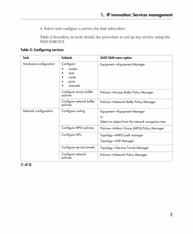
4. Select and configure a service for that subscriber.
Table 2 describes, in more detail, the procedure to set up any service using the 5620 SAM GUI.
Table 2: Configuring services
Task Subtask 5620 SAM menu option
Hardware configuration Configure:
• routers• slots• cards• ports• channels
Equipment→Equipment Manager
Configure access buffer policies
Policies→Access Buffer Policy Manager
Configure network buffer policies
Policies→Network Buffer Policy Manager
Network configuration Configure routing Equipment→Equipment Manager
or
Select an object from the network navigation tree
Configure MPLS policies Policies→Admin Group (MPLS) Policy Manager
Configure LSPs Topology→MPLS path manager
Topology→LSP Manager
Configure service tunnels Topology→Service Tunnel Manager
Configure network policies
Policies→Network Policy Manager
(1 of 2)
5

1. IP innovation: Services management
Figures 2 shows a sample service configuration form using the 5620 SAM client GUI.
Service-related policy configuration
Configure access ingress policies
Policies→Access Ingress Policy Manager
Configure access egress policies
Policies→Access Egress Policy Manager
Configure scheduling policies
Policies→Scheduler Policy Manager
Configure slope policies Policies→Slope Policy Manager
Configure accounting policies
Policies→Accounting Policy Manager
and
Policies→File Policy Manager
Configure access list policies
Policies→Acl IP Filter Manager
Policies→Acl MAC Filter Manager
Subscriber configuration — Service Management→Manage Subscribers/Services
Service configuration Create VLL service
Create VPLS
Create IES
Create IP VPN service
Service Management→Create Service
Task Subtask 5620 SAM menu option
(2 of 2)
6

1. IP innovation: Services management
Figure 2: Configuring services
What are the 7750 SR and 7450 ESSThe 7750 SR and 7450 ESS are the industry’s first scalable, purpose-built IP/MPLS service nodes. With its service-oriented architecture and built-in OAM features, the nodes enable efficient and profitable SLA-based services, such as:
• Internet Enhanced Service• IP Virtual Private Networks (7750 SR only)
• Virtual Leased Lines• Virtual Private LAN Service
Internet Enhanced Service (IES)IES is a routed connectivity service where the customer communicates with an IP router interface to send and receive Internet traffic. IES supports line-rate and subrate services and a variety of billing models, including usage- and destination-based billing.
Figure 3 shows an example of an IES.
7

1. IP innovation: Services management
Figure 3: IES
Key benefits of IES
• To the customer, it seems as though there is a direct connection to the Internet.
• The service provider can apply billing, ingress and egress shaping, and policing to the traffic.
• IES supports filters (ACLs) at a 10 Gb/s line rate.
• Each system supports up to 2000 BGP peers and 1 000 000 routes (FIB).• The service is easily deployed and managed using the 5620 SAM portfolio.
13280
Corporate headquarters
Serviceprovider
infrastructure
17252
Corporate headquarters
Corporate headquarters
7750 SR
7750 SR
7750 SR
8

1. IP innovation: Services management
IP Virtual Private Network (IP VPN)Based on RFC 2547bis, the IP VPN, sometimes called VPRN, is a class of VPN that allows the connection of multiple sites in a routed domain over a provider-managed IP/MPLS network. The managed routers provide virtual routing and forwarding for IP VPNs, and extend the service reach nationally or globally using the IP/MPLS backbone.
Supported IP VPNs include Ethernet, Packet over SONET, and Frame Relay access circuits. This support enables service providers to deliver a flexible range of service options to enterprise customers.
Figure 4 shows an example of an IP VPN.
Figure 4: IP VPN
13280
Serviceprovider
infrastructure
17253
IP VPN
7750 SR
7750 SR
Branch office
Branch office
Corporate headquarters
7750 SR
9

1. IP innovation: Services management
Key benefits of IP VPN
• To the customer, all sites appear as though they are connected to a routed domain, where the service provider’s edge equipment behaves like the customer’s own routers.
• The service provider can reuse the IP/MPLS infrastructure to securely offer multiple services.
• Smaller customers can “outsource” the complexity of routing to the service provider.
• It provides better route control and address aggregation.
• This highly scalable service supports, per router, up to 2000 IP VPN customers, 1 000 000 routes, and 2000 BGP peers.
• The service is easily deployed and managed using the 5620 SAM portfolio.
Virtual Leased Line (VLL)VLL service offers an efficient replacement of traditional private line service, leveraging the statistical multiplexing benefits of a packet-based network. The VLL service offers Ethernet point-to-point connections, where customer data is encapsulated and transported across a service provider’s IP/MPLS network.
Figure 5 shows an example of an VLL service.
10

1. IP innovation: Services management
Figure 5: VLL service
Key benefits of Ethernet VLL
• To the customer, it seems as though a leased line exists between the two locations.
• The service provider can offer SLAs with the service and apply billing, ingress and egress shaping, and policing to all traffic.
• Each 7750 SR system supports up to 64 000 VLLs, and all of them are managed from the same 5620 SAM platform.
• The VLL service is fully transparent to the subscriber’s data and protocols. • The VLL service has locally significant VLAN tagging.• The VLL service does not use customer-address learning, which improves
scaling for other services.
• The service is easily deployed and managed using the 5620 SAM portfolio.
Corporate headquartersServiceprovider
infrastructure
Branch office
Branch office
Point-to-point links (VLL)
17250
7750 SR
7750 SR
7750 SR
11

1. IP innovation: Services management
Virtual Private LAN Service (VPLS)VPLS is a class of VPN that allows the connection of multiple sites in a single, bridged domain over a service provider’s IP/MPLS network. This market-leading service allows customer sites to be in the same LAN, regardless of their location. The simplification of the customer-provider boundary allows enterprise customers to seamlessly integrate their LANs and WANs.
Figure 6 shows an example of an VPLS.
Figure 6: VPLS
13280
Corporate headquartersServiceprovider
infrastructure
VPLS
7750 SR
7750 SR
Branch office
Branch office
17251
7750 SR
Branch office
12

1. IP innovation: Services management
Key benefits of VPLS for the service provider’s customer
• All sites are connected to a single, switched virtual LAN.
• VPLS is a transparent, protocol-independent, multipoint service.• The Ethernet LAN-WAN interface reduces equipment complexity, which lowers
the cost of ownership; removes the Layer 2 protocol conversion between LAN and WAN; and requires no training on WAN technologies, such as frame relay.
• Customers retain complete control over routing, allowing WAN connectivity with little involvement by the service provider.
• The addition of new sites is easy and requires no reconfiguration at existing sites.
Key benefits of VPLS for the service provider
• The service provider can reuse the IP/MPLS infrastructure to offer multiple services.
• The service provider can apply billing, ingress and egress shaping, and policing to the traffic, delivering per-service SLAs.
• First-line technicians are not involved with customer routing issues.• The addition of new sites requires no reconfiguration at existing sites.• VPLS enables faster service and bandwidth provisioning.
• Each router supports up to 4000 services and 128 000 MAC addresses, and the 5620 SAM manages all the services on multiple routers.
• The VPLS has locally significant VLAN tagging, reducing complexity and management overhead.
• H-VPLS support enables service providers to use either MPLS spokes or stacked VLANs (Q in Q) to delimit and identify different customers
• The service is easily deployed and managed using the 5620 SAM portfolio.
13

1. IP innovation: Services management
14

Reliable platforms for growth
Services need management platforms that can scale with your business. Build services on cost-effective platforms, and grow the network as sales grow.
Management architectureThe 5620 SAM is designed to run on a number of platforms and operating systems, allowing the service provider to maximize investments in the NOC infrastructure or to invest in a lower-cost infrastructure. For example, the 5620 SAM server can operate in a PC environment running Windows 2000 or XP or a Sun environment running Solaris 9.
15

2. Reliable platforms for growth
The 5620 SAM was designed to reliably handle large-scale, high-bandwidth service delivery. The easy-to-install system uses an object-oriented, distributed architecture that allows:
• improved scaling• a higher transaction load• load balancing
• in-band and out-of-band management configuration for management redundancy to protect against link failures
• scheduled management IP address pings to test reachability• easy-to-install APIs that support OSS components using an JMS/XML interface
• ease-of-integration with the 5620 NM, Release 6.2 or later, to provide end-to-end management
Figure 7 shows the 5620 SAM management architecture.
Figure 7: 5620 SAM management architecture
13280
OperatorGUI
OSS applications 7750 SR
Equipmentmanager
Faultmanager
Topologymanager
Servicemanager
Securitymanager
CorrelationBusiness logicMediation layerRate compression
17245
RMI/JMS
SNMP
XML/JMS
Database
Server
7750 SR 7750 SR
7750 SR
7750 SR
16

2. Reliable platforms for growth
Each tier in the architecture operates on a separate server or server cluster. This improves scaling and introduces load balancing, which improves performance. For example, the 5620 SAM can process up to 1000 SNMP traps a second and an operator can save a complex VLL service configuration in less than two seconds.
Table 3 lists the management architecture components, and how each component is designed to provide robust network management.
Table 3: 5620 SAM components
Component Use Advantages
5620 SAM database Stores data using a tailored Oracle database.
Separate tier architecture improves transaction rates and can be configured for redundancy to secure data in the event of a failure.
5620 SAM server Correlates data and provides rules and associations between subscribers, services, equipment, and faults.
Business logic provides a rules engine and correlation function.
Mediation layer provides multiple interfaces to the managed routers.
Information model to map to the database.
Multiple interfaces, such as SNMP and Telnet, to the managed network.
Provides the XML interface and tools to integrate OSS applications in a multivendor management environment.
Implements rules and correlation to ensure changes to services configuration and alarms are updated to all necessary components of the managed network.
5620 SAM client Java-based operator GUI that allows operators to provision, manage, and monitor services in a secure environment.
Full suite of management applications in four modules are available from any network management console.
Operator requests are validated before being submitted to the 5620 SAM database by the 5620 SAM server.
17

2. Reliable platforms for growth
Supported deployment sizesThe platform flexibility allows the 5620 SAM to support large-scale deployments of services:
• 250 000 services running on up to 100 managed routers• 60 simultaneous operational GUI clients
• 50 000 outstanding alarms• 1000 I/O slots that contain up to 2000 cards and 30 000 ports• 20 000 network interfaces, 30 000 LSPs, and 60 000 service tunnels (SDPs)
• 1 000 000 circuits• 4094 VLAN IDs per access port• unlimited statistics files, user and performance logs, and alarm history record
databases, assuming adequate storage is available
18

Selling and managing customer services
The 5620 SAM portfolio—especially the 5620 SAM-P provisioning tools and the 5620 SAM-A service assurance tools—provides an easy-to-use GUI that facilitates the rapid deployment of services. The key benefits to the service provider and the customer are:
• lower integration tax for service providers when introducing new managed network elements
• improved communication between the customer care organization and the operations staff
• simplified QoS configuration to offer the exact services customers need• increased operator confidence in handing over fully operational services, that
meet agreed to parameters, to the customer
• increased customer confidence and satisfaction by giving operators the tools to associate customers to services quickly when problems are detected
19

3. Selling and managing customer services
Creating services made easyThe advantages of the Alcatel 5620 SAM-P module include:
• end-to-end service configuration using a sequence of configuration forms• listing hardware and software utilization statistics on a per-service basis
• template-based creation of policies, which specify the classification, policing, shaping, and marking of traffic for multiple services
• tightly integrated fault management that correlates equipment problems with the services that use the equipment
• tightly integrated OAM tools
• changing a single service component (such as a service) rather than multiple ports on multiple devices
• separating tunnel configurations and transport from the services that they carry
Figure 8 shows the components of the easy-to-use, configuration form-based 5620 SAM service configuration form.
20

3. Selling and managing customer services
Figure 8: Service configuration form
13280
Easy to move back andforth between configurations
to verify data entry
Easy-to-followsteps walk operatorsthrough the service
creation process
Choose a servicetype from thedrop-down list
17244
21

3. Selling and managing customer services
Service location and subscriber managementA single port can carry hundreds of services to dozens of customers. The 5620 SAM-A provides the tools a service provider needs to rapidly associate equipment with the subscribers that use the equipment for their services. This association:
• increases operator and customer confidence by ensuring services are fully operational before being deployed to the customer, or to troubleshoot a specific customer’s problems
• smooths integration with key service management and OSS partnerships
• establishes and maintains customer satisfaction by empowering operators and other service provider staff to rapidly associate subscribers to services
• extends support for operators to find services based not only on physical equipment or the subscriber’s name, but also by service tunnels (SDPs) and LSPs
From the 5620 SAM-A subscriber manager form, you can create the customer’s service, and then monitor the service’s status, resources, alarms, and statistics. Figure 9 shows an example of how services are associated with a subscriber. In this example, Subscriber 2 is using three services. You can click on the other tab buttons to view information about the subscriber’s account, for example, the circuits forwarding customer traffic.
The subscriber manager provides a one-stop location for operators to monitor subscriber services, to track alarms, to verify service connections, to test connectivity before customer hand over, to quickly get subscriber contact information, and to troubleshoot and fix problems efficiently.
22

3. Selling and managing customer services
Figure 9: Subscriber services listed from a subscriber form
Policies and QoSThe 5620 SAM-P supports the template-based creation of rules that govern how network traffic is handled and prioritized. These rules are called policies. There are three types of policies:
• service management• routing management• network management
All the equipmentused to enable servicescan be viewed from the
subscriber's data
Details of thesubscriber's services
Check faults andrun diagnostics forselected services
17243
23

3. Selling and managing customer services
Service management policies specify how service traffic is handled by network resources such as interfaces, ports, cards, and circuits. These policies can be used by multiple resources on multiple services. Examples of service management policies include access ingress, access egress, and network policies.
Routing management policies specify routing configuration according to specifically defined parameters. There are two routing management policies; routing policies and MPLS administrative group policies.
Service and routing management policies are globally and seamlessly distributed to routers when they are used by resources on the router. They can also be manually distributed to routers. Policy configurations can also be changed locally when you configure a network resource, for example, during service configuration or modification.
Network management policies specify how the 5620 SAM communicates with network resources, handles alarms, manages statistics used for billing, and stores information. Examples of network management policies include alarm, mediation, and accounting policies.
The 5620 SAM-P supports the creation and modification of policies using configuration forms. For example, Figure 10 shows an Access Ingress Policy creation form.
24

3. Selling and managing customer services
Figure 10: Access Ingress Policy creation form
Table 4 describes in more detail the available policy types.
25

3. Selling and managing customer services
Table 4: Policies
Policy type Policy Applied to Description
Service management
Access Ingress
Access interface Defines ingress classification, policing, shaping, and marking on the ingress side of the interface.
This policy defines ingress service forwarding class queues and map flows to those queues. When an access ingress policy is created, it always has two queues defined that cannot be deleted: one for default unicast traffic and one for default multipoint traffic.
Access Egress
Access interface Defines egress classification, policing, shaping, and marking on the egress side of the interface.
This policy defines egress service queues and map forwarding class flows to queues. In the simplest access egress policy, all forwarding classes are treated like a single flow and mapped to a single queue.
Network Policy
Network interface Defines egress QoS marking and ingress QoS interpretation for traffic on core network IP interfaces.
On ingress, a network policy maps incoming DSCP and EXP values to the forwarding class and profile state for traffic received from the core network. On egress, the policy maps the forwarding class and profile state to DSCP and EXP values for traffic to be transmitted into the core.
Slope Access port (slope only)
Network daughter card
Network port
Defines RED slopes behavior for the access port, network daughter card, or port. Buffer pools are created to dedicate buffer resources for a set of queues. The buffers for a queue are allocated from a single buffer pool based on the queue’s forwarding class.
Network Queue
Scheduler Access ingress interface
Access egress interface
Defines hierarchical rate limiting and scheduling to govern queue scheduling.
Scheduler policies determine the order in which queues are serviced. All ingress and egress queues operate within the context of a scheduler.
ACL IP Filter Network interface
Access interface
Circuit
Controls network or access traffic into or out of an interface or circuit based on IP or MAC matching criteria.
IP and MAC filter policies specify a forward or drop action for packets based on information specified in the match criteria.
MAC IP Filter Access interface
Circuit
(1 of 2)
26

3. Selling and managing customer services
QoS includes:
• eight forwarding classes of services, from high priority to best effort• 8000 ingress and 8000 egress queues per card
• queue buffering per card at an average of 200 ms of ingress and 200 ms of egress buffering at 10 Gb/s
• H-QoS, which provides a common set of virtual schedules to manage bandwidth over a set of customer services
QoS allows IP services to have various forwarding classes. A forwarding class provides network elements with a method to weigh the relative importance of one packet over another in a different forwarding class.
Queues are created for a specific forwarding class to determine how the queue output is scheduled into the switch fabric and the type of parameters that the queue accepts. The packet’s forwarding class—along with the in-profile and
Network management
Alarm Alarm logs
Alarms
Defines how the network management system handles individual incoming alarms, and how alarm logs are created and stored.
File — Manages file policies related to how data is collected and stored on the router before being transferred to the network management system.
Accounting Interfaces
Service
Circuit
Manages accounting policies related to the specified counters and scheduling of accounting statistics collected from the routers.
Mediation 5620 SAM Defines how the network management system communicates with the network.
Poller 5620 SAM Defines how the network management system polls the network for updates, and sets per-MIB polling rules.
Routing management
Routing Routing instance Manages route policies.
Admin Group (MPLS) policy manager
MPLS interfaces
LSPs
LSP paths
Configures MPLS administrative groups and defines the groups to which an MPLS interface, LSP, or LSP path belongs.
Policy type Policy Applied to Description
(2 of 2)
27

3. Selling and managing customer services
out-of-profile state—determines how the packet is queued and handled at each hop along its path to a destination egress point. The eight forwarding classes are described in Table 5.
Table 5: Forwarding classes
In Figure 11, the overall SLA is set at 10 Mb/s with varied committed information rates (CIRs) and peak information rates (PIRs) per type of service. When higher priority traffic is below its CIR, the ‘spare’ bandwidth becomes available and lower priority traffic can burst up to the overall PIR of 10 Mb/s.
Figure 11: Per-service QoS
ID Name Class type Intended for
7 Network Control High-Priority Network control traffic
6 High-1 Delay- or jitter-sensitive traffic
5 Expedited Delay- or jitter-sensitive traffic
4 High-2 Delay- or jitter-sensitive traffic
3 Low-1 Assured Assured traffic (default for network management traffic)
2 Assured Assured traffic
1 Low-2 Best-Effort Best-effort traffic
0 Best-Effort Best-effort traffic
13280
TOS=0=normal
TOS=1=priority
TOS=4=video
TOS=5=voicePIR= 2 Mb/s
CIR= 2 Mb/s
PIR= 2 Mb/s
CIR= 2 Mb/s
PIR= max
CIR= 0
PIR= max
CIR= 0
OverallSLA= 10 Mb/s
17274
28

3. Selling and managing customer services
The 5620 SAM supports H-QoS scheduling mechanisms. H-QoS provides the ability to manage bandwidth across multiple queues from single or multiple access interfaces for customer services.
The building blocks for H-QoS include a series of easy-to-configure policy configuration forms:
• Scheduler policies to define a hierarchy of virtual schedulers that govern queues. Participation in scheduler policies is defined when access interfaces are configured or modified.
• QoS access ingress and egress policies to specify how subscriber traffic is mapped into queues, and specify queue classification, queue parameters and marking.
Figure 12 shows one of the H-QoS configuration steps—the configuration of an access ingress policy. This configuration form specifies the QoS settings and the IP address match criteria that will pass traffic into a specific queue. Queues are defined by a packet’s forwarding class. As well, the queue is aligned with a scheduler.
29

3. Selling and managing customer services
Figure 12: Access ingress policy for H-QoS configuration
Accounting and performance monitoring using statisticsMonitor network performance and collect accounting statistics using service- and equipment-related statistics counters from the managed routers.
You can create statistics policies for:
• service access points to collect accounting data
• network ports to monitor performance data
Service access point statistical counters are used to measure usage on each individual service queue, which can then be rolled up to bill for services. This information can be valuable to determine customer usage and link utilization.
30

3. Selling and managing customer services
You can control how often the counters are collected and applied to all services. You can create accounting policies that determine which statistical classes, and counters within each class, are collected. These accounting policies can be applied to services such as VPLS. The statistics generated and collected can then be used to:
• check throughput to confirm SLAs• correlate for billing• monitor the quality of services delivered
There can be combinations of flat-rate, destination-based, or usage-based billing. Figure 13 shows how accounting policies are applied to service access interfaces, also known as SAPs, to collect different levels of statistical data.
Figure 13: Accounting statistics policies applied to services
SAP 1
SAPs on Port1/1-Egress
Policy 1Policy 2
Policy 3
Applyaccounting
policies
SAP 2
SAP 4
SAP n...
Highpriority
Best effort
17185
High level of statistics accounting
SAP 3
Log1
Log2
Log3
File policy
Port 1/1Standardcounters
forphysical
and logicalequipment
statsServicequeue
Servicequeue
Low level of statistics accounting
Stat1
Stat2
Stat3
Stat4
Stat1
Stat2
Stat3
Stat4
Stat5
Stat6
Stat7
Stat8
Stat9
Stat10
OctetsPackets
IngressRecordTypesFileInterval
31
3. Selling and managing customer services
As shown in Figure 13, there are different accounting statistic policies applied to the services. The subscriber using service access point 3 on port 1/1 as a service egress point has two services, high priority and best effort. The statistics policies applied to each service type are different. For the high-priority service, more statistics are collected than for the best-effort service.
Network port statistics are used to measure performance within each forwarding class queue as defined on the network port. This information can be used to track port performance and network traffic patterns for future capacity planning and traffic engineering.
You can view the near-real time performance statistics data from select configuration forms, or from the historical log files. The types of performance statistics you can collect include:
• Access Interface Stp• Interface
• Tunnel• LSP• PE
• SONET or SDH
32

Networking made easy
Although the managed routers were designed and optimized to deliver revenue-generating services, the underlying system is a robust, highly scalable router, suitable for Internet peering and a wide range of ISP applications.
You can quickly enable the IP/MPLS infrastructure and routing protocols you need to offer services to your customers.
Routing protocol and signaling support and implementationThe 5620 SAM allows you to configure routing protocols and signaling methods, and navigate to the router parameters. Each router can support multiple routing protocols and signaling methods.
You use the Network, IS-IS, and OSPF tabs on the 5620 SAM GUI navigation tree to view and configure parameters that set and manage routing protocols. The routing protocols are enabled on the routers when you configure the routers. The Layer 3 interfaces are configured when you configure the routing instance on the router. You can then configure the routing protocols for the specific Layer 3 interfaces.
33

4. Networking made easy
Configuration is performed using routing protocol configuration forms, as shown in Figure 14.
Figure 14: BGP configuration form
Table 6 lists supported routing protocols and signaling methods.
34

4. Networking made easy
Table 6: Routing protocol and signaling information
Type Details
Label Distribution Protocol (LDP) signaling
There are two types of LDP signaling:
• Targeted LDP (T-LDP)• Downstream Unsolicited LDP (DU-LDP)
T-LDP is used to distribute labels for VPLS and VLLs.
DU-LDP is used to create tunnels between PEs for VPLS, VPN, and IP VPNs.
Routing Information Protocol (RIP)
RIP is an Interior Gateway Protocol (IGP) that uses a distance-vector algorithm to determine the best route to a destination, using hop count as the deciding factor.
In order for the protocol to provide complete information on routing, every router in the domain must participate in the protocol. RIP, a UDP-based protocol, updates its neighbors, and the neighbors update their neighbors.
Border Gateway Protocol (BGP)
BGP is an inter-autonomous system (AS) routing protocol. An AS is a network or a group of routers logically organized and controlled by a common network administration.
BGP enables routers to exchange network reachability information. AS paths are the routes to each destination. There are two types of BGP, internal BGP (IBGP) and external BGP (EBGP).
• Within an AS, IBGP is used to communicate.• Outside of an AS or between ASs, EBGP is used to
communicate with peers in different autonomous systems.
Resource Reservation Protocol (RSVP) signaling
RSVP is a network control protocol used to request specific qualities of service from the network for particular application data streams or flows.
RSVP is also used by routers to deliver QoS requests to all nodes along the path of the flows and to establish and maintain state to provide the requested service.
(1 of 2)
35

4. Networking made easy
The GUI facilitates complicated protocol configuration and management as follows.
1) Configure the router to support the protocols you plan to use from the check mark boxes on the router configuration form.
2) Configure the parameters to enable routing protocols on the Layer 3 interfaces.
3) Associate the Layer 3 interfaces with the network ports.
4) Configure the protocol-appropriate settings, for example for OSPF setting up at least one OSPF area and associating the router with the area.
Routing information starts to be exchanged once the ports are cabled together.
Open Shortest Path First (OSPF)
OSPF is a hierarchical link state protocol. OSPF is an IGP used within large ASs. OSPF routers exchange relevant interface information with neighbors once the neighbors are discovered. The information exchange enables all participating routers to establish a network topology map. Each router applies the Dijkstra algorithm to calculate the shortest path to each destination in the network. The routing table is then calculated.
Because OSPF is hierarchical, routers are configured in logical groups called areas. There are two main types of areas:
• backbone area• standard area
Intermediate System to Intermediate System (IS-IS)
IS-IS is a link state interior gateway protocol that uses the shortest path first algorithm to determine routers. Routing decisions are made using the link state information. IS-IS entities are comprised of:
• networks, which are autonomous system routing domains• intermediate systems, which are routers• end systems, which are network devices that send and
receive PDUs
End systems and intermediate system protocols allow routers and nodes to identify each other. IS-IS sends out link state updates periodically through the network, so each router can maintain current network topology information.
Type Details
(2 of 2)
36

4. Networking made easy
For example, OSPF configuration planning is essential to organize routers, backbone, non-backbone, stub, NSSA areas, and transit links. The GUI makes it easy:
• to create a single OSPF backbone area which contain the area border routers• to create several areas containing the other routers for larger networks• to place all routers in the OSPF backbone area for smaller networks
Figure 15 shows the Network tab in the navigation tree and the primary icons representing enabled routing functionality.
Figure 15: Network tab in the navigation tree
13280
Alarm status forobject indicated by
the icon color
Network tab, showing IP routerobject details, is highlighted
Context-sensitivemenu optionsfor this object
Routing protocols,configured for thisrouting instance
BGP confederation 8 isconfigured for this routing instance,
and has these members
17336
37

4. Networking made easy
Using the GUI, you can:
• create OSPF or BGP areas and add Layer 3 interfaces to them• view and configure routing instances• configure and assign Layer 3 interfaces
• assign routers to the OSPF area• create BGP confederations
MPLS and LSPsMultiprotocol label switching (MPLS) is used to set up connection-oriented paths over a connectionless IP network. MPLS facilitates network traffic flow and provides a mechanism to engineer network traffic patterns independently from routing tables. MPLS sets up a specific path for a sequence of packets. The packets are identified by a label that is inserted in each packet. MPLS is independent of any routing protocol but is considered multiprotocol because it works with IP, ATM, and frame relay network protocols.
Use the 5620 SAM to easily configure parameters for:
• MPLS and RSVP interfaces• MPLS paths
• LSPs• service tunnels (SDPs)
To configure RSVP LSPs, an MPLS path must first be created between two routers. An LSP can then be created between the two routers and be associated with the MPLS path.
Services are transported across a network using service tunnels, which can use GRE or MPLS as the underlying transport mechanism. For networks that use MPLS, an MPLS path mesh and an LSP mesh should be created before you start associating LSPs with the service tunnels. LSPs and service tunnels are unidirectional, thus both LSPs and service tunnels must be created in both directions.
38

4. Networking made easy
The 5620 SAM supports the ability to tailor the LSPs according to network design needs:
• loose hop MPLS paths for fast rerouting around problem routers or to find the best network route
• one-to-one backup LSPs to provide a detour at each potential point of repair• facility backup using MPLS label stacking to protect potential failure point
Figure 16 shows how provisioning of the IP/MPLS backbone can be performed from both the 5620 SAM-P and the 5620 SAM-O.
Figure 16: IP/MPLS backbone configuration
13280
7750 SR
7450 ESS
7450 ESS
National IP/MPLS
backboneMetro EthernetService network
Metro EthernetService network
Database
The provisioning of theMPLS or IP backbone overMPLS or GRE tunnels and themapping of VLAN tags to the LSP or GRE tunnel is done usingthe 5620 SAM-P or 5620 SAM-O
7750 SR
7750 SR
7450 ESS
Server
SAM-O OSS Interface
17343
39

4. Networking made easy
40

Managing network CAPEX and OPEX
The 5620 SAM helps you keep tabs on your equipment investment:
• implementation of router functionality to ease OPEX• add equipment as demand warrants to manage CAPEX
• tools to inventory provisioned and in-use equipment• view services and topology using custom-designed map views• pinpoint control for resynchronization of network elements
• integrated Layer 2 and Layer 3 end-to-end management with the 5620 management portfolio
Implementation of functionalitySome partially implemented network management systems force system administrators and operators to devise complex operational procedures that move back and forth between a GUI and the CLI.
The 5620 SAM implements the router’s functionality. You can have less skilled operators use the GUI to perform all necessary management tasks, and you can give more senior staff or administrators access to CLI, Telnet, and FTP cut-through for more complex tasks.
41

5. Managing network CAPEX and OPEX
Configuration managementUse the 5620 SAM’s point-and-click configuration management to quickly:
• configure installed hardware, or pre-configure, the physical equipment, such as access and network ports
• turn up pre-configured physical equipment when it is installed in the chassis
• move from Layer 1 and Layer 2 equipment configuration to Layer 3 router interface and network protocol configuration, such as OSPF, MPLS, and IS-IS
• create and apply appropriate policy attributes to reduce provisioning time• filter and list inventories of equipment
• provision services between routers and the CPEs• test services and equipment with service assurance tools, such as OAM
diagnostics, between all provider edge endpoints before handing off the service to customers
Configure equipment and interfaces
Figure 17 shows a GUI that displays the equipment in multiple ways.
42

5. Managing network CAPEX and OPEX
Figure 17: Equipment management drawings and forms
• The navigation tree on the left shows the Equipment tab and a daughter card opened to view its ports.
• The equipment manager form on the right displays the shelf for the managed router.
• The physical port configuration form in the centre is open for port 4/1/1, to show the parameter information that can be configured for the managed equipment from the General tab.
43

5. Managing network CAPEX and OPEX
The 5620 SAM-E equipment manager allows network administrators and operators to:
• view drawings, LEDs, storage device information, and statistics about the routers in their administrative domain
• view the services that traverse or terminate on equipment• provision and pre-provision equipment in preparation for subscriber services
• view, configure, monitor the state of, and manage the equipment hierarchy—from the chassis to the ports
• configure network and access policies for network objects, such as ingress buffer policies for a port
• manage hardware alarms
Figure 18 shows the navigation tree, and how its use can help manage the network.
44

5. Managing network CAPEX and OPEX
Figure 18: Using the navigation tree
Manage all equipment types
All shelf and slot configurations can be managed.
13280
Alarm stats for objectindicated by the icon color
Equipment tabis highlighted
Slots of the routershowing configured MDAs,
daughter cards,ports, and channels
Details of the objectvaries accordinglyto type of object
All objects havecontext-sensitiveright-click menus
17335
45

5. Managing network CAPEX and OPEX
Supported Ethernet cards include:
• 10/100 Ethernet with 60 ports• 100FX Ethernet with 20 ports• Gigabit Ethernet with 10- and 5-port configurations
• 10 Gigabit Ethernet with 1 port• 10/100/1000 Ethernet
Supported SONET/SDH cards include:
• OC3/STM1 and OC12/STM4 16- and 8-port configurations• OC48/STM16 4- and 2-port configurations
• OC192/STM64 with 1 port
Supported channelized cards include:
• OC12/STM4 channelized from the DS3/E3 level to the DS0 level• DS3/E3 down to the T1/E1 channel level• DS3/E3 T1/E1 channel down to the DS0 level
Supported ports include:
• Fast Ethernet (10/100BASE-T)
• Gigabit Ethernet (1000BASE-T)• 10 Gigabit Ethernet (10GBASE-T)• OC3/STM1 to OC192/STM64 SONET and SDH
You configure ports as network or access ports.
• Network ports connect and pass core network-facing traffic.• Access ports connect and pass customer-facing traffic.
Network ports are used in the service provider transport or infrastructure network, such as an IP/MPLS-enabled backbone network. Access ports are associated with a service access point (SAP), a subscriber, and a service to provide connectivity services to the subscriber, for example, a VLL service.
A variety of encapsulation types are supported on both the network and access ports, including BCP, Null, Dot1 Q and Q in Q for VLAN stacking.
46

5. Managing network CAPEX and OPEX
Link Aggregation Groups (LAGs) can be configured to increase the bandwidth available between two network devices, depending on the number of links installed (up to 8). LAGs also provide redundancy if one or more links in the LAG fail. All physical links in an LAG link combine to form one logical network interface.
You can configure the Link Aggregation Control Protocol (LACP) to maintain link configuration information, attach or detach ports to a LAG, and determine LAG states.
All physical and logical equipment components, from the chassis to the ports, are fully managed by the 5620 SAM. For each network and access port, you can use the GUI to view and configure parameters using the tab buttons.
• General tab—data includes port mode and encapsulation type parameters• Ethernet or SONET/SDH tabs—data includes framing and frame size
parameters
• Policies tab data—includes ingress and egress buffer policy settings• Terminations tab—lists services or interfaces that terminate on the port• Interface tab—lists IP routing information and configuration parameters
• Services tab—correlates subscriber services that use the Layer 2 or Layer 3 interface associated with the port
• Statistics tab—contains other tabs of statistics counters collected for the port
Viewing and managing inventoriesYou can generate and save lists of inventory, based on configurable sets of data, to send to an in-house inventory management system.
• All applications provide inventory support, so you can inventory physical components, such as cards, and logical components, such as MPLS paths.
• You can use the 5620 SAM-O to develop OSS applications to generate and feed inventory data to third-party applications, such as billing software.
• Filter the lists of GUI table data to only save or show data of interest.
• Save the data output in text, HTML, or XML formats.
Figure 19 shows how the 5620 SAM can help you track inventories.
47

5. Managing network CAPEX and OPEX
Figure 19: Inventory elements
Topology managementTwo network topology maps are available on the 5620 SAM:
• service topology map• service path topology map
13280
Open the contextual inventorymenu from the column headings
A count of the number ofobjects in this list
Click on column headingto sort objects in ascending
or descending order
Show or hidecolumns of information
as needed
Save the inventory ofobjects to a file forstorage or use by
downstream applications
17271
48

5. Managing network CAPEX and OPEX
The topology manager provides:
• logical and physical maps of the network elements and the services carried on those network elements
• management of the physical and logical elements of services• GRE/MPLS tunnels, LSPs, and routing topologies, to show network transport
• a view of all services provided to a subscriber• a view of outstanding alarms and problems to provide a simplified logical view of
faults for network operators
Figure 20 shows the map elements, which indicates all of the data that you can view.
Figure 20: Map elements
13280
Launch one ofmany types of maps
Connection statusonline
Indicates the mostserious alarmed raised
Right-click to view contextappropriate views,
for example, properties
Offline, 5620 SAM unableto manage view alarms to
determine the problem
Arrange icons forease of management
Type of mapyou are viewing
List appropriate: paths LSPs hops routes service tunnels
17260
49

5. Managing network CAPEX and OPEX
Resynchronization with network elementsThe 5620 SAM simplifies network provisioning by allowing you to discover managed routers and commit them to the database for management.
An easy-to-use discovery manager helps you create any number of discovery rules to scan the network, setting both the types of elements to be discovered, and how often 5620 SAM rescans the network.
A discovery rule can contain more than one rule element. For example, you can configure one rule element to discover a subnet, and configure another rule element to exclude specific IP addresses from the subnet.
In addition, from the same GUI form, you can set polling intervals to specify how often all router MIB elements of discovered and managed routers are polled for changes to their MIBs. Any change to the MIB triggers the 5620 SAM to re-read the entire MIB and update its database. You can detail individual rules for individual MIBs, depending on your network needs.
End-to-end, integrated management solutionsWhatever your management requirements, the 5620 SAM offers a range of integration solutions.
• For smaller networks, service providers may not have an IP OSS in place and may not want an Alcatel management solution, particularly for small network deployments. You can use HP OpenView NNM integration because it provides an entry level solution at an affordable price.
• For complex integration of Layer 2 and Layer 3 elements, the 5620 SAM and the 5620 NM can be integrated in the same network management domain for a seamless management solution.
Integration using the 5620 NM
Adding new IP/MPLS-based services to an existing multiservice ATM and/or Frame Relay network requires a management system that can enable a smooth but rapid integration of existing NOC and OSS systems. A management suite that enables this transition helps reduce OPEX by increasing operational efficiency.
50

5. Managing network CAPEX and OPEX
For standalone IP/MPLS and metro Ethernet networks, the 5620 SAM suite of modules provides all the necessary tools. For integrated Layer 2 and Layer 3 management, the 5620 NM is the multi-service IP network manager of choice.
The 5620 NM is used today by hundreds of the world’s largest networks. Its service management applications provide full network management of traditional Frame Relay and ATM services, as well as infrastructure management capabilities for IP/MPLS and metro Ethernet network equipment.
The 5620 NM is capable of discovering IP router elements, including the 7750 SR. As well, the 5620 SAM can be launched from a 5620 NM management platform. This flexibility:
• reduces training costs for operators by using similar GUIs• extends service awareness by defining each segment of a service that, when
aggregated, constitutes the complete end-to-end service of your customers
• normalizes operational procedures for Layer 2 and Layer 3 network management
Figure 21 shows the 5620 NM portfolio solution that manages end-to-end numerous services and technologies. For example, a VPLS that is delivered using an IP/MPLS network delivered by the 7750 SR reaches the end customer using an ATM or Frame Relay network.
51

5. Managing network CAPEX and OPEX
Figure 21: Integrated service delivery and management
13280
IP/MPLSnetwork
5620 NMwith
5620 SAM client
XML,CMIP,CORBA7750 SR
7750 SR
VLAN-VC interworkingfor VPLS FR-MPLS
mediation for FR
LSPfull mesh
GigabitEthernet
Packetover SONET
AlcatelServiceNetwork
ATM/Frame Relaymultiservice
FrameRelay
FrameRelay
ATM
xDSL
7670 RSP
OSSapplications
17304
10/100Ethernet
10/100Ethernet
VPLSElementary service #1Elementary service #2
Frame Relay VLL serviceElementary service #1Elementary service #2
52

Integrated fault management and OAM
Use a wide range of standards-based, correlated alarms and industry-leading OAM tools to:
• monitor services to validate and ensure SLA agreements• receive instant notification about which equipment alarms have affected services
• check end-to-end connectivity before turning up customer services• perform pings and traces from the GUI and view the results from the same form
53

6. Integrated fault management and OAM
Intelligent alarm fault managementThe fault management system provides:
• impact analysis and correlation of alarms on equipment to service-affecting faults on a per-service basis using 5620 SAM-A
• color-coded alarms to show operational status of equipment, services, and interfaces in real time
• alarm policy control so administrators can specify individual alarm display characteristics, suppression rules, severity assignments, escalation, and storage
• wide range of X.733 and vendor-specific alarms• point-and-click alarm management from a dynamic alarm list, and from
equipment and services
• operator notes and acknowledgment to track the work as the problem is fixed• alarm data logged in an historical alarm database for trend analysis and records
Figure 22 shows how business logic is applied to network alarms, which in turn updates subscriber services and ensures that all affected services are updated.
54

6. Integrated fault management and OAM
Figure 22: Alarm handling
From the GUI, operators have a number of tools to fine-tune, define, and track alarms. They can:
• view the relationship between incoming alarms and the affected objects, such as the effect of equipment alarms on service operation
• determine and then set specific policies for each alarm type, for example, the alarm’s incoming severity and its escalated severity
• track the most important alarms using color codes, for example, sort all red critical alarms.
Fault management
Businesslogic
Rules Card 1/2 downFault
alarm(s)
Customeraccess ports
List of failed objectsCard 1/2 down
Affected objectsPort 1SAP-a
Service-zSAP-b
Service x...etc
sortableaffected usersaffected equipmentaffected services
Methods
Alarms onclient GUI
OSS
7750 SR
Card
17167
55

6. Integrated fault management and OAM
Figure 23 shows the alarm relationships and the GUI tools to manage them.
Figure 23: Alarm relationships on the GUI
Service assurance with diagnosticsThe proper delivery of services requires that a number of operations occur correctly for the service to pass traffic to subscribers according to SLAs.
It is critical that service providers be able to test service connectivity, not just interface status. The 5620 SAM-A module provides a set of in-band and out-of-band packet-based OAM tools.
13280
From the dynamic alarm list
MPLS path isaffected by alarm
Affectedport
How alarm ishandled determined
by alarm policy
17345
56

6. Integrated fault management and OAM
These OAM tools can be initiated by the operator from numerous forms on the GUI, for example, you can open a form for an individual subscriber and enable and initiate OAM diagnostics for that subscriber’s services.
The following OAM tools are supported:
• MTU OAM
• tunnel OAM• circuit OAM• LSP ping and traceroute
• multiple MAC-level OAMs, including MAC ping• IP VPN ping and trace
Figure 24 shows how OAM troubleshooting tools can be used to fix service problems. A MAC ping can help diagnose connectivity issues.
57

6. Integrated fault management and OAM
Figure 24: Sample OAM diagnostic - MAC ping
MTU OAM
The MTU OAM diagnostic provides a tool for service providers to determine the exact frame size that is supported between the service ingress and service egress termination points, to within one byte. Use the MTU OAM to:
• determine the maximum frame size supported• solve troubleshooting issues that are related to equipment used across the
network core which may not be able to handle large frame sizes
13280
Request:VPLS-PING
MAC-E1
Response:VPLS-PING
MAC-E1
17308
MAC E1
58

6. Integrated fault management and OAM
Tunnel OAM
Tunnel OAM performs in-band unidirectional or bidirectional connectivity tests on service tunnels. The OAM packets are sent in-band, in the tunnel encapsulation, so they follow the same path as the service traffic. The response can be received out-of-band in the management plane, or in-band using the data plane for a bidirectional test.
Circuit OAM
Circuit OAM provides end-to-end connectivity testing for an individual service. This diagnostic operates at a higher level than the tunnel OAM because it verifies connectivity for an individual service, rather than connectivity across the service tunnel. This allows you to isolate a problem within the service, rather than the port that is the endpoint of the service tunnel.
The diagnostic tests a service ID for correct and consistent provisioning between two service endpoints. From a circuit OAM you can:
• verify that the local and remote service exists• determine the current state of the local and remote service
• ensure that local and remote service types are correlated• ensure that the same customer is associated with the local and remote service• ensure that there is a service to circuit association with both the local and remote
service
• ensure that the local and remote ingress and egress service labels match
LSP ping and traceroute
LSP ping and traceroute diagnostics provide a mechanism to detect data plane failures in MPLS LSPs. The diagnostics are modeled after the ICMP echo request/reply used to detect and isolate faults in IP networks.
59

6. Integrated fault management and OAM
MAC OAM diagnostics
Multiple MAC OAM diagnostics are supported, including:
• MAC ping is used to determine the existence of an egress service access point binding of a given MAC address within a VPLS service
• MAC trace is used to display the hop-by-hop route of MAC addresses used to reach the target MAC address at the far-end
• MAC populate is used to populate a service FIB with an OAM-tagged MAC entry
IP VPN ping and trace
The IP VPN ping and IP VPN trace OAM diagnostics are enabled from the VRF site of the subscriber’s IP VPN service. The ping determines the existence of the far-end egress point of the service. IP VPN pings can be sent in band or out of band. The IP VPN trace OAM displays the hop-by-hop route used to reach the target address at the far-end. Traces can be sent in band or out of band.
60

Securing your IP network edge
Security in the IP world has never been easier to implement than with the 5620 SAM’s user account templates and full support of router-aware security policies. You can:
• secure the management domain to limit operator access and privileges• set up authentication servers
• encrypt routing protocol communications across the managed network
Security end-to-endThe system administrator uses the security menus to control user privileges on the 5620 SAM and control access to the equipment. 5620 SAM users are assigned to a group that has been configured with permissions for one or more functional areas of the 5620 SAM.
61

7. Securing your IP network edge
The system administrator can perform the following tasks:
• create 5620 SAM groups and configure 5620 SAM group permissions• create 5620 SAM and managed router user accounts, assign users to groups, and
specify user privileges• set Telnet or SSH access
• configure RADIUS and TACACS+ authentication to allow controlled access to the equipment using router-based user accounts
• modify users, passwords, groups, and policies• suspend and reinstate users
Table 7 describes the group permissions for 5620 SAM accounts.
Table 7: Group permissions
Permission group Functional area access Use to
Admin All 5620 SAM functional areas
Perform all 5620 SAM tasks, including administering users and groups.
Device Mgmt Equipment management
Configure and manage equipment operations and inventory.
Interface Mgmt Interface management Configure interface properties.
Topology Mgmt Topology management Monitor and manage network elements.
Subscriber Mgmt Subscriber management
Configure and manage subscriber accounts.
Service Mgmt Service management Configure and manage service distribution paths and services.
QoS Mgmt QoS policies Configure and manage QoS and filter policies.
Fault Mgmt Fault policies Monitor and manage outstanding alarms, acknowledge and perform severity changes, manage the alarm history database, and modify fault policies.
Operator Read-only access to all functional areas, but security is hidden
Monitor applications and faults.
(1 of 2)
62

7. Securing your IP network edge
RADIUS is an access server authentication, authorization, and accounting (AAA) protocol. It provides a standardized method of exchanging information between a RADIUS client, located on the router and managed by the 5620 SAM, and an external RADIUS server. You can use the 5620 SAM to create policies, accounts, and connections to RADIUS and TACACS+ servers that complement the security policies created on the managed routers.
RADIUS functionality provides an extra layer of login security. The RADIUS client relays user account information to the RADIUS server. The server authenticates the user and returns user privilege information to the RADIUS server. This sets the level of access the user has to the router. For example, the user may not be able to FTP information to the router.
Figure 25 shows a RADIUS policy configuration form.
Operations System maintenance Perform system maintenance functions such as managing logs, database backups and restores, and software downloads, adding and removing network nodes, and specifying mediation policies.
CLI CLI Launch a Telnet or SSH session from the selected network element.
Permission group Functional area access Use to
(2 of 2)
63

7. Securing your IP network edge
Figure 25: RADIUS policy configuration form
Operators can also specify encryption for PDUs between routers sharing routing information, to ensure traffic routing security and eliminate the risk of compromising routing tables. Operators configure the GUI parameters that enable MD5 authentication and the authentication key to authenticate neighboring routers before a protocol session is set up, for example, BPG.
64

Open interfaces and OSS integration
The 5620 SAM-O OSS interface provides open interface and OSS support for third-party applications that you can develop to provision, manage faults, and inventory your network. This OSS enables service providers to de-risk integration costs by:
• extending Layer 1 through Layer 3 network and service management into one comprehensive object model
• delivering integrated management solutions that simplify OSS integration
• using Alcatel’s partnerships with leading OSS vendors to reduce integration time and effort while minimizing risks to existing operation centre configurations
• combining the 5620 NM’s proven OSS interfaces, to help preserve current OSS applications and extend support for new service offerings
• inter-operating with best-of-breed ISV applications
Open interfacesUse the 5620 SAM-O module to enable the entire 5620 SAM suite of applications. An OSS application would use the 5620 SAM-O XML interface to configure or access network management information in the 5620 SAM database, send
65

8. Open interfaces and OSS integration
configuration requests to the managed network routers, create provisioning applications to turn up services, or create a plug-in to an existing inventory application to collect data about the resources in use.
An SOAP encapsulation is used to securely transmit requests to the 5620 SAM server running the 5620 SAM-O from the OSS application.
This carrier-grade OSS interface allows:
• provisioning of services and policies• real-time alarm and event fault management notifications
• equipment and inventory management
The information model of the managed network consists of:
• packages— each package has one or more groups of related domain objects (classes), data types, bitmasks, and enumerations
• domain objects (classes)—contain the properties of the class• data types—contain standard XML schemas as defined by the W3C consortium;
for example, strings and integers; extended XML schemas, for example, IpAddresses; and other XML schemas, for example, bitmasks
• information structures—contain both the domain objects (classes) and the properties of the information, which are called elements in the XML but are also known as parameters in the CLI or GUI
• inheritance—in which domain objects and properties interact with each other
Requests are constructed and sent to the 5620 SAM-O for processing. For example, the following sequence outlines how you generate requests for fault management information using XML/SOAP.
• Specify a domain object (class type) for the request based on the fmTypes.xsd file.
• Specify a valid information structure for the request based on the fmTypes.xsd file.
• Specify a valid method for the request based on the fmMethods.xsd file.• Construct a valid SOAP request.
• Send the request.• Receive a response or exception to the request.
66

8. Open interfaces and OSS integration
There are numerous fault management methods that you can use to execute specific fault management tasks based on the OSS application’s intended uses. For example, you can clear faults on all alarms in the managed network using the fm.FaultManager.clearFaults method. You can also create an application to monitor a specific router and get a stream of all alarms from that router using the fm.FaultManager.findFaultsOnObject method.
The OSS provides functionality to monitor events in real-time, and keep on top of changes to the managed network; it enables the same functionality as the GUI, and provides the ability to export the entire output of the database and save it in a series of file formats.
67

8. Open interfaces and OSS integration
68

Standards compliance
Table 8 lists the standards compliance and specifications for the 5620 SAM portfolio. See the appropriate equipment General Information books for a complete list of supported MIBs and standards compliance.
Table 8: Network management compliance
Standard Description
X-721 SMI
X-734 State model
M.3100/3120 Equipment and connection models
TMF 509/613 Network connectivity model
RFC 1157 SNMPv1
RFC 1657 BGP4-MIB
RFC 1850 OSPF-MIB
(1 of 3)
69

A. Standards compliance
RFC 1907 SNMPv2-MIB
RFC 2011 IP-MIB
RFC 2012 TCP-MIB
RFC 2013 UDP-MIB
RFC 2096 IP-FORWARD-MIB
RFC 2138 RADIUS
RFC 1724 RIPv2-MIB
RFC 2206 RSVP-MIB
RFC 2558 SONET-MIB
RFC 2571 SNMP-FRAMEWORK-MIB
RFC 2572 SNMP-MPD-MIB
RFC 2573 SNMP-TARGET-&-NOTIFCATION-MIB
RFC 2574 SNMP-USER-BASED-SM-MIB
RFC 2575 SNMP-VIEW-BASED-ACM-MIB
RFC 2576 SNMP-COMMUNITY-MIB
RFC 2665 EtherLike-MIB
RFC 2819 RMON-MIB
RFC 2863 IF-MIB
RFC 2864 INVERTED-STACK-MIB
RFC 2987 VRRP-MIB
RFC 3014 NOTIFICATION-LOG-MIB
RFC 3273 HCRMON-MIB
W3C XML 1.0
W3C Namespaces in XML
W3C XML schemas
W3C SOAP 1.2
draft-ietf-disman-alarm-mib-04.txt —
Standard Description
(2 of 3)
70

A. Standards compliance
draft-ietf-ospf-mib-update-04.txt —
draft-ietf-mpls-lsr-mib-06.txt —
draft-ietf-mpls-te-mib-04.txt —
draft-ietf-mpls-lsp-ping-02.txt —
draft-ietf-mpls-ldp-mib-07.txt —
draft-ietf-isis-wg-mib-05.txt —
IANA-IFType-MIB —
IEEE8023-LAG-MIB —
Standard Description
(3 of 3)
71

A. Standards compliance
72

Associated documents
Alcatel is committed to providing superior product documentation in convenient and effective formats. Development and delivery of documentation online is one way that the Alcatel continues to meet the changing needs of customers.
Product manuals and documentation are available through the Alcatel Support Documentation Service at www.alcatel.com. If you are a new user and require access to this service, contact your Alcatel account representative.
See the 5620 SAM user documentation for more detailed information about using the network management suite of applications.
• Alcatel 5620 SAM Installation Guide for more information about installing the database, server, and client 5620 SAM software
• Alcatel 5620 SAM User Guide for more information about using the GUI to perform network management tasks
• Alcatel 5620 SAM-O OSS Interface Developer Guide for XML-based OSS application development
73

B. Associated documents
See the 7750 SR user documentation for more detailed information about router installation, functionality, and specific CLI commands.
• 7750 SR OS Router Guide for information about configuring the router• 7750 SR OS Services Guide for information about policies and services• 7750 SR OS System Guide for information about system configuration
• the appropriate 7750 SR Installation Guides for information about installing routers
See the appropriate Release Descriptions and Release Notices for more general information about the status of specific product releases, including supported functionality, restrictions, and configuration updates.
74

Glossary
5620 SAMAlcatel 5620 Service Aware Manager
The 5620 SAM is the network manager portfolio of modules for the 7750 SR.
5620 SAM clientThe 5620 SAM client provides a GUI to configure IP network elements.
5620 SAM databaseThe 5620 SAM database stores network objects and configurations.
5620 SAM serverThe 5620 SAM server mediates between the 5620 SAM database, 5620 SAM client, and the network.
5620 SAM-AAlcatel 5620 SAM Assurance
The 5620 SAM-A provides service assurance functionality.
75

Glossary
5620 SAM-E5620 SAM Element Manager
The 5620 SAM-E provides network element configuration and management functionality.
5620 SAM-OAlcatel 5620 SAM Open Interfaces
The 5620 SAM-O provides an XML interface for OSS applications to interact with the 5620 SAM.
5620 SAM-PAlcatel 5620 SAM Provisioning
The 5620 SAM-P provides service provisioning functionality.
5620 SRM5620 Service Router Manager
The Release 1.2 name of the 5620 SAM.
7450 ESS7450 Ethernet Service Switch
7750 SR7750 Service Router
The 7750 SR is a router that provides scalable, high-speed private data services with SLAs.
7750 SR-1The one-slot version of the 7750 SR chassis.
76

Glossary
7750 SR-7The seven-slot version of the 7750 SR chassis.
7750 SR-12The 12-slot version of the 7750 SR chassis.
ACLaccess control list
An access control list, which is also known as a filter policy, is a template applied to services or ports to control network traffic into (ingress) or out (egress) of an SAP or port based on IP and MAC matching criteria. Filters are applied to services to examine packets entering or leaving a SAP or network interface. An ACL policy can be used on several interfaces. The same filter can be applied to ingress traffic, egress traffic, or both.
APIapplication programmable interface
ARPaddress resolution protocol
ASICapplication specific integrated circuit
An integrated circuit accommodating a group of functions that are dedicated to supporting a specific application in an optimized way. This is in contrast to integrated circuits accommodating functions that can be used to implement a wide variety of applications.
ATMasynchronous transfer mode
77

Glossary
Asynchronous transfer mode is a very high-speed switching and transmission technology. ATM is a high bandwidth, low-delay, packet-like switching and multiplexing technique. Usable capacity is segmented into 53-byte fixed-size cells, consisting of header and information fields, allocated to services on demand.
BGPborder gateway protocol
BGP is an IETF standard EGP used to propagate routing information between autonomous systems.
CAPEXcapital expenditure
CIRcommitted information rate
The CIR is the guaranteed minimum rate of throughput between two end-user devices over a network under normal operating circumstances. This rate, measured in bits or kb/s, is used in congestion control procedures.
CLIcommand line interface
The CLI is an interface that allows the user to interact with the operating system by typing alphanumeric commands and optional parameters at a command prompt.
CoSclass of service
CoS is the degree of importance assigned to traffic. During queuing and forwarding, service points give preferential treatment to traffic that originates on elements configured for premium CoS.
78

Glossary
CPEcustomer premises equipment
Network equipment that resides on the customer’s premises.
CPUcentral processing unit
The CPU is the part of a computer that performs the logic, computational, and decision-making functions. The CPU is typically a single computer chip.
DCEdata circuit-terminating equipment
DIAdirect Internet access
Also referred to as Internet enhanced service.
DLCIdata link connection identifier
DSAPdestination service access point
DTEdata terminal equipment
ECMPequal cost multipath
A method of distributing traffic to multiple destinations over several equivalent paths.
79

Glossary
EGPexterior gateway protocol
A routing protocol used by gateways in two-level Internets.
EJBEnterprise JavaBeans
An architecture for setting up program components, written in the Java programming language, that run in the server parts of a computer network that uses the client/server model. Enterprise JavaBeans is built on the JavaBeans technology for distributing program components (which are called Beans, using the coffee metaphor) to clients in a network.
Enterprise JavaBeans offers the advantage of being able to control change at the server rather than having to update each individual computer with a client whenever a new program component is changed or added.
EMCElectromagnetic Compatibility
Epipe serviceAnother term for Ethernet virtual leased line (VLL).
EthernetEthernet is a popular LAN technology based on bus topology.
faultA fault is a failure or defect in a network, causing the network, or part of the network, to malfunction.
80

Glossary
FCAPSFCAPS is the abbreviation for a broad categorization of network and service management activities, including:
• fault management• configuration management
• accounting/administration management• performance management• security management
FIBforwarding information base
FIB is the set of information that represents the best forwarding information—for example, next IP hop—for each destination (or set thereof). The entries in the FIB are derived from the reachability information held in the RIB, subject to administrative routing.
forwarding classA forwarding class, also called a CoS, provides to network elements a method to weigh the relative importance of one packet over another in a different forwarding class. Each forwarding class is important only in relation to other forwarding classes.
Queues are created for a specific forwarding class to determine the manner in which the queue output is scheduled into the switch fabric and the type of parameters the queue accepts. The forwarding class of the packet, along with the in-profile or out-of-profile state, determines how the packet is queued and handled (the per-hop behavior at each hop along its path to a destination egress point).
Table 1 describes the forwarding classes supported by the 7750 SR.
81

Glossary
Table 1: Forwarding class types
FTPfile transfer protocol
FTP is the Internet standard client-server protocol for transferring files from one computer to another. FTP generally runs over TCP or UDP.
GREgeneric routing encapsulation
GUIgraphical user interface
A GUI is a computer user interface that incorporates graphics to make software easier to use.
H-QoShierarchical QoS
Forwarding class type
Designation Class type Description
Network control NC High priority For network control traffic
High-1 H1 For a second network control class or delay- and jitter-sensitive traffic
Expedited EF For delay- and jitter-sensitive traffic
High-2 H2 For delay- and jitter-sensitive traffic
Low-1 L1 Assured For assured traffic (default)
Assured AF For assured traffic
Low-2 L2 Best effort For best-effort traffic
Best effort BE For best-effort traffic
82

Glossary
HTMLhyper-text markup language
H-VPLShierarchical VPLS
ICMPInternet control message protocol
ICMP is an extension to the Internet protocol. ICMP supports packets containing error, control, and informational messages. The ping command, for example, uses ICMP to test an Internet connection.
IEEEInstitute of Electrical and Electronic Engineers
IESInternet Enhanced Service
IES is a routed connectivity service where the subscriber communicates with an IP router interface to send and receive Internet traffic. An IES has one or more logical IP router interfaces, each with an SAP that acts as the access point to the subscriber network. IES allows customer-facing IP interfaces to participate in the same routing instance used for service network core routing connectivity. IESs require that the IP addressing scheme used by the subscriber be unique between other provider addressing schemes and possibly the entire Internet.
While the IES is part of the routing domain, the usable IP address space may be limited. This allows a portion of the service provider address space to be reserved for service IP provisioning and be administered by a separate but subordinate address authority.
IP interfaces defined within the context of an IES must have an SAP associated as the access point to the subscriber network. Multiple IESs are created to segregate subscriber-owned IP interfaces.
83

Glossary
IETFInternet Engineering Task Force
I/Oinput/output
IPInternet protocol
IP is part of the TCP/IP family of protocols that describes the protocol that tracks the Internet address of nodes, routes outgoing messages, and recognizes messages. IP is used in gateways to connect networks at OSI network level 3 and higher.
IP VPNInternet protocol virtual private network
A class of VPN that allows the connection of multiple sites in a routed domain over a provider-managed MPLS network.
IS-ISintermediate system to intermediate system
IS-IS is an ISO standard link-state routing protocol. Integrated IS-IS is an extension that allows IS-IS to be used for route determination in IP networks.
ISOInternational Standards Organization
An international organization that is responsible for a wide range of standards, including those relevant to networking. ISO developed the OSI model, a popular networking reference model.
ISPInternet service provider
84

Glossary
ITU-TInternational Telecommunications Union — Telecommunication Standardization Sector
The ITU is an international organization within the United Nations, where governments and the private sector coordinate global telecommunication networks and services. The ITU Telecommunication Standardization Sector (ITU-T) is one of the three Sectors of the ITU. The ITU-T's mission is to ensure efficient and on-time production of high-quality standards, in the form of recommendations, covering all fields of telecommunications.
JMSjava messaging service
JMS is used by the 5620 SAM-O to retrieve event and real-time alarm information from the 5620 SAM.
LAGlink aggregation group
An LAG increases the bandwidth available between two nodes by grouping up to eight ports into one logical link. The aggregation of multiple physical links allows load sharing and offers seamless redundancy. If one of the links fails, traffic is redistributed over the remaining links. Up to eight links can be supported in a single LAG, and up to 64 LAGs can be configured on a node.
LANlocal area network
LDPlabel distribution protocol
LDP is a signaling protocol used for MPLS path setup and teardown. An LDP is used by LSRs to indicate to other LSRs the meaning of labels used to forward traffic.
LDP is defined in RFC 3036.
85

Glossary
LEDlight-emitting diode
LLClogical link control
LLC is the higher of the two data link layer sublayers defined by the IEEE. The LLC sublayer handles error control, flow control, framing, and MAC-sublayer addressing. The most prevalent LLC protocol is IEEE 802.2, which includes both connectionless and connection-oriented variants.
LMIlocal management interface
A set of enhancements to the basic frame relay specification.
LSPlabel switched path
LSPs support MPLS functionality and allow network operators to perform traffic engineering. There are two types of LSPs:
• static LSPA static LSP specifies a static path. All routers that the LSP traverses must be configured manually with labels. No signaling is required.
• signaled LSPA signaled LSP is an LSP that is set up using a signaling protocol. The signaling protocol allows labels to be assigned from an ingress router to an egress router. Signaling is triggered by the ingress router. Only the ingress router, and not the intermediate routers, must be configured. Signaling also facilitates path selection.
LSRlabel switched router
86

Glossary
An LSR is an MPLS node that runs MPLS control protocols and is capable of forwarding packets based on labels. An MPLS node may also be capable of forwarding native Layer 3 packets.
MACmedia access control
MAC is a sublayer of the data link layer, defined in IEEE 802.2 specifications, that is responsible for accessing the LAN medium. The MAC layer handles the recognition and identification of individual network devices.
Every computer and network node has a MAC address that is hardware-encoded.
MD5message digest version 5 algorithm
MD5 is a type of authentication. The MD5 algorithm takes an input message or arbitrary length and produces a 128-bit message digest of the input.
menu barThe menu bar is a tool on the GUI that organizes tasks across broad headings. You can perform functions on the application by selecting an action from the menu bar.
MIBManagement Information Base
The MIB is the database of an SNMP-managed device that store objects representing the components of the network.
MPLSmultiprotocol label switching
MPLS is a technology in which forwarding decisions are based on fixed-length labels inserted between the data link layer and network layer headers to increase forwarding performance and flexibility in path selection.
87

Glossary
MTUmaximum transmission unit
MTU is the largest unit of data that can be transmitted over a particular interface type in one packet. The MTU can change over a network.
navigation treeThe navigation tree displays a view of all managed equipment, services, and protocols, and allows you to navigate through these components.
network topologyA network topology is the layout of a network, which can include the way in which elements in a network, such as nodes, are connected and how they communicate.
NOCnetwork operations center
OAMOperations, Administration, and Maintenance
Network maintenance includes connectivity verification, alarm surveillance, continuity checking, and performance monitoring.
OC-NOptical Carrier - level N
An optical SONET signal carried at the speed of N, for example, OC-12 is a signal at 622.08 Mb/s.
OPEXoperations expenditure
OSIopen systems interconnection
88

Glossary
A reference model of protocols organized in seven layers, with the aim of facilitating the interworking of equipment from different manufacturers.
OSPFOpen Shortest Path First
OSPF is an IETF standard link-state routing protocol used to determine the most direct path for a transmission in IP networks.
OSPF-TEOSPF traffic engineering
OSSoperational support system
Network management system supporting a specific management function, such as alarm surveillance and provisioning, in a carrier network.
OUIorganizational unique identifier
Three octets assigned by the IEEE in a block of 48-bit LAN addresses.
PDUprotocol data unit
PEprovider edge
PIDprofile identifier
PIRpeak information rate
89

Glossary
The maximum rate at which a connection can carry traffic.
POSpacket over SONET
PPPpoint-to-point protocol
PPP is an IETF standard protocol that allows a computer to use TCP/IP with a standard telephone line and a high-speed modem to establish a link between two (and only two) terminal installations.
pseudo-wireAnother term for virtual leased line (VLL).
Q-in-QQ-in-Q refers to stacked VLANs. The term derives from 802.1Q, an IEEE standard that defines the operation of VLAN switch/bridges which permit the definition, operation, and administration of VLAN topologies within a switched/bridged LAN infrastructure. The protocol uses a labeling or tagging mechanism that identifies the VLAN number. It supports the ability to prioritize the VLAN traffic based on prioritization labels (802.1P).
QoSQuality of Service
QoS is a term for the set of parameters and their values that determines the performance of a virtual circuit. This service level is usually described in a network by delay, bandwidth, and jitter.
RADIUSremote authentication dial-in user service
A remote user authentication, authorization, and accounting protocol.
90

Glossary
RFCRequest For Comment
The IETF document category that contains many documents, including standards, produced by the IETF.
RIBrouting information base
RIB-INRIB ingress
RIPRouting Information Protocol
RIP is a Bellman-Ford routing protocol based on distance vector algorithms that measure the shortest path between two points on a network in terms of the number of hops between those points. Various forms of RIP are used to distribute routing information in IP, XNS, IPX, and VINES networks.
routerA router is an interface device between two networks, connecting LANs to LANs or LANs to WANs. It selects the most cost-effective route for moving data between multiprotocol LANs, making sure that only one route exists between source and destination devices. Routers make forwarding decisions based on network layer addresses.
RSVP-TEResource Reservation Protocol is used two ways:
• RSVP is the process of reserving network and host resources to achieve a QoS for an application.
• RSVP is an IP-based protocol that is used for communicating application QoS requirements to intermediate transit nodes in a network. RSVP uses a soft-state mechanism to maintain path and reservation state in each node in the reservation path.
91

Glossary
SAPservice access point
SDHsynchronous digital hierarchy
SDH is an ITU-T standard for optical interfacing that is technically consistent with SONET.
SDPservice distribution path
A service distribution path acts as a logical way of directing traffic from one router to another router through a unidirectional service tunnel. The 5620 SAM uses the term service tunnel. The SDP terminates at the far-end router, which directs packets to the correct service egress SAPs on that device. A distributed service consists of a configuration with at least one SAP on a local node, one SAP on a remote node, and an SDP binding the service to the service tunnel.
SFPsmall form factor pluggable
SFP is a specification for a new generation of optical modular transceivers. The devices are designed for use with small form factor connectors and offer high-speed and physical compactness. They are hot-swappable.
SLAservice-level agreement
An SLA is a service contract between a network service provider and a subscriber that guarantees a particular QoS. SLAs are used for providing network availability and data-delivery reliability.
SNAPsubnetwork access protocol
92

Glossary
SNAP is an Internet protocol that operates between a network entity in the subnetwork and a network entity in the end system. SNAP specifies a standard method of encapsulating IP datagrams and ARP messages on IEEE networks. The SNAP entity in the end system makes use of the services of the subnetwork and performs three key functions: data transfer, connection management, and QoS selection.
SNMPSimple Network Management Protocol
A protocol used for the transport of network management information between a network manager and a network element. SNMP is the most commonly used standard for most interworking devices.
SONETSynchronous Optical Network
SONET is an ANSI standard for fiber-optic transmission of high-speed digital traffic. SONET allows internetworking of transmission products from multiple vendors and defines a physical interface, optical line rates known as OC signals, frame format, and an OAM protocol. The base rate is 51.84 Mb/s (OC-1), and higher rates are multiples of the base rate.
SONET uses synchronous high-speed signals and provides easy access to low-speed signals by mapping them into VTs.
SONET is a North American standard that is technically consistent with SDH, which is international.
SSHsecure shell
STM-NSynchronous Transport Module - level N
An SDH signal carried at the speed of N, for example, STM-4 is a signal at 622.08 Mb/s.
93

Glossary
subscriberA subscriber is a customer who buys services from a network provider.
TACACS+terminal access controller access control system
A remote user authentication, authorization, and accounting protocol.
TCP and TCP/IPtransmission control protocol and transmission control protocol/Internet protocol
Protocols widely used for communicating across interconnected networks. TCP provides transport functions that ensure that all information sent is received correctly at the final destination. IP defines the format of the routing information.
TelnetTelnet is the Internet-standard TCP/IP protocol for remote terminal connection service. It allows a user at one site to interact with a remote timesharing system at another site as if the user’s terminal connected directly to the remote machine.
The Telnet command and program are used to log in from one Internet site to another. It gets the user to the login prompt of another host.
tiered architectureTiered architecture refers to the way in which the GUI and the network management components use a Java-based technology that provides distributed, secure, and scalable applications. This tiered architecture allows for scaling and fair load balancing, which improves performance.
UDPuser datagram protocol
UDP is a minimal transport network protocol above the IP network layer that does not guarantee datagram delivery.
94

Glossary
VCvirtual channel
VLANvirtual local area network
VLLvirtual leased line
A virtual leased line is a type of VPN where packets are transported in a point-to-point manner.
Other terms used for VLL: Epipe service and pseudo-wire.
VPLSvirtual private LAN service
A VPLS is a type of VPN in which a number of sites are connected in a single bridged domain over an IP/MPLS network.
VPNvirtual private network
VPRNvirtual private routed network
Another term for IP VPN.
VRRPvirtual router redundancy protocol
VTvirtual tributary
95

Glossary
SONET format for mapping a lower-rate signal into a SONET payload. For example, VT-1.5 is used to transport a DS1 signal.
WANwide area network
windowWindows are forms, panels of information, equipment drawings, or graphics that appear on a screen. Windows commonly allow a user to input data and initiate functions, but some windows simply display information.
XMLextensible markup language
XML defines the syntax to customize markup languages. The markup languages are used to create, manage, and transmit documents across the Web.
96

Index
Numerics
5620 NMintegration with 5620 SAM, 50
5620 SAMintegration with 5620 NM, 50security, 61
5620 SAM architecture, 155620 SAM client, 175620 SAM database, 175620 SAM server, 175620 SAM-A, 225620 SAM-O, 655620 SAM-P, 20
A
access ports, 45alarm management, 54Alcatel IP migration solutions, iii
B
BGP, 35BGP/MPLS VPN; See IP VPNbilling for services, 30
C
circuit OAM, 59configuration management, 42
D
diagnostics with OAM, 56documentation
additional, 73
97

Index
E
Epipe service; See VLLequipment
alarm correlation, 54ease of management, 42GUI configuration, 42MDAs, 45ports, 45synchronization, 50
EthernetLAN-WAN interface, 12point-to-point connections, 10
F
forwarding classes, 28
H
HP OpenView integration, 50HQoS, 29
I
IES, 7Internet enhanced service; See IESinventory management, 47IP VPN, 9
OAM diagnostics, 60IS-IS, 35
L
LANsvirtual private, 12
Layer 3 VPN; See IP VPNLDP, 35LSP, 38LSP ping and traceroute, 59
M
MAC OAM, 60maps, 48MDAs supported, 45MIBs NMS support, 69MPLS, 38MTU OAM, 58
N
network management policies, 23network management standards compliance, 69
network ports, 45network synchronization, 50
O
OAM, 56circuit, 59IP VPN ping and trace, 60LSP ping and traceroute, 59MAC, 60MTU, 58tunnel, 59
98

Index
open interfaces, 65OSPF, 35OSS support, 65
P
performance accounting using statistics, 30
platform support, 15policies overview, 23ports supported, 45provisioning
5620 SAM-P, 20pseudo-wire; See VLL
Q
QoS, 23
R
RADIUS, 61RFC 2547; See IP VPNRIP, 35router functionality enabled on GUI, 41router security, 61routing policies, 23routing protocol
ease of configuration, 36using the GUI, 33
RSVP, 35
S
scalability sizing, 18security, 61service assurance
5620 SAM-A, 22service configuration, 4service management policies, 23service provider challenge, iiiservice routing, 1services
IES, 7IP VPN, 9VLL, 10VPLS, 12
signaling methodsusing 5620 SAM, 33
specifications, 69standards compliance, 69statistics, 30subscriber management, 22
T
TACACS+, 61topology management, 48tunnel OAM, 59
U
user documentation, 73user management, 61
99

Index
V
virtual leased line; See VLLvirtual private LANs; See VPLSVLL, 10VPLS, 12VPNs
IP, 9VPRN; See IP VPN
X
XML OSS interface, 65
100


Alcatel and the Alcatel logo are registered trademarks of Alcatel. All other trademarks are the property of their respective owners. Alcatel assumes no responsibility for the accuracy of the information presented, which is subject to change without notice. © 05 2004 Alcatel. All rights reserved. 3CL 00469 0554 TQZZA Ed.01 17894
Recommended