www.ecn.nl
Advanced Membrane Reactors for Carbon-Free Fossil Fuel Conversion
Daniel Jansen, Wim Haije, Michiel Carbo, Virginie Feuillade, Jan Wilco Dijkstra,Ruud van den Brink

Contents
The project
Objectives
R&D results ECN
Reactor design
System analysis
Materials science
Catalyst testing
Conclusions

Advanced Membrane Reactors in Energy Systems Development of novel membranes for membrane reactors.
Objective:
The purpose of this project is to develop H2 and CO2 membranes to allow combinations of natural gas reforming or WGS with H2 or CO2 separation in separation enhanced reactors, i.e. membrane reactors, for carbon-free hydrogen production or electricity generation.

systemstudies
reactordesign
membrane & catalyst
development
materialsresearch
experimentalresults
reactorrequirements
desired specificationsfundamental knowledgecharacterization
overall efficiencieseconomics
reactor testspatentsIP
IPpublications
newdevelopments
Task 1. System analysis and thermodynamic evaluations Task 2. Hydrogen membrane research & development Task 3. CO2 membranes research & development Task 4. Catalyst screening Task 5. Reactor modelling and design
Executed by ECN Executed by TUD Executed by ECN+TUD Executed by ECN Executed by ECN
The ECN GCEP project layout

Application:
NGCC with CO2 membrane reformer reactor
Advantages compared to H2 membrane reformer:• eliminating the requirement of water gas shift reactors: cost reductions • offering higher conversion efficiencies at lower temperatures • H2 rich stream remains at elevated pressure and temperature • CO inhibition of membrane not foreseen• no need for CO2 cleaning section
Steam reformermembrane reactor
Natural gas
H2O
Pre-reformer
Steamsweep
H2/
CO2
Steam Reforming
Combined Cycle

Application:
IGCC with CO2 membrane water gas shift reactor
Advantages compared to H2 membrane WGS reactor:• eliminating the requirement of LT water gas shift reactor: cost reduction• incomplete CO conversion in WGS does not reduce the IGCC efficiency but lowers CO2 capture ratio• H2 rich stream remains at elevated pressure and temperature• CO inhibition of membrane not foreseen• no need for CO2 cleaning section
Water gas shiftmembrane reactorCoal
H2O
G-E gasifier
Steamsweep
O2
Pre-shift
G-E product gas(around 1300 oC)
CoolerT=300 oC
H2O
Combined Cycle
CO2

Main Question
Membrane application:‘Everybody’ agrees on the fact that either H2 or CO2 selective membranes are viable options for carbon capture technologies
But……..:‘Nobody’ cares or dares to look into the process boundary conditions:Are both membranes equally fit to operate in a certain process??
Reactor Design/System analysisCO2 versus H2 selective membranes
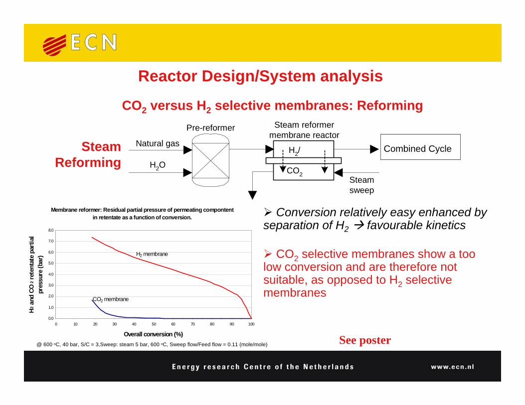
Membrane reformer: Residual partial pressure of permeating compontent in retentate as a function of conversion.
0.0
1.0
2.0
3.0
4.0
5.0
6.0
7.0
8.0
0 10 20 30 40 50 60 70 80 90 100
Overall conversion (%)
H2 a
nd C
O2 r
eten
tate
par
tial
pres
sure
(bar
)
CO2 membrane
H2 membrane
Steam reformermembrane reactor
Natural gas
H2O
Pre-reformer
Steamsweep
H2/
CO2
Steam Reforming
Combined Cycle
Conversion relatively easy enhanced by separation of H2 favourable kinetics
CO2 selective membranes show a too low conversion and are therefore not suitable, as opposed to H2 selective membranes
Reactor Design/System analysis
CO2 versus H2 selective membranes: Reforming
@ 600 oC, 40 bar, S/C = 3,Sweep: steam 5 bar, 600 oC, Sweep flow/Feed flow = 0.11 (mole/mole) See poster

0,0
5,0
10,0
15,0
20,0
25,0
70 75 80 85 90 95 100
WGS conversion (relative to product gas) (%)
Part
ial p
ress
ure
H2 a
nd C
O2
in re
tent
ate
(bar
)
H2 membrane
CO2 membrane
Water gas shiftmembrane reactorCoal
H2O
G-E gasifier
Steamsweep
O2
Pre-shift
G-E product gas(around 1300 oC)
CoolerT=300 oC
H2O
Combined Cycle
Water gas shiftmembrane reactorCoal
H2O
G-E gasifier
Steamsweep
O2
Pre-shift
G-E product gas(around 1300 oC)
CoolerT=300 oC
H2O
Combined CycleCombined Cycle
H2 permeation results in better CO2recovery and CO conversion but CO2permeation does not perform much worse
Complete system and exergy analysis needed to really determine all pros and cons
Reactor Design/System analysis
CO2 versus H2 selective membranes: IGCC
CO2
@300 oC, 42.2 bar, S/C just enough to complete water gas shift, excess catalyst, Sweep: steam 17 bar, 300oC See poster

Reactor Design/System analysisIGCC with H2 WGS Membrane Reactor
N2H2, CO,
H2O, CO2
Slag
PulverizedCoal
Quench Gas
BFW
IP Steam
HP Steam
Syngas
H2
H2, N2
O2
Air
N2
N2
Air
CO2
Stack
H2-WGSMembrane
Reactor
ASU Dry-fed CoalGasifier
GasCooler
GasTurbine
HRSG SteamTurbine
CO2Liquefaction
WGSGasCleaningSection
IP SteamH2O
IP Steam
CryogenicDistillation
CO, H2, N2, CH4

Reactor Design/System analysisIGCC with CO2 WGS Membrane Reactor
CO2, H2O
H2, CO,H2O, CO2
Slag
PulverizedCoal
Quench Gas
BFW
IP Steam
HP Steam
Syngas
H2, N2
O2
Air
N2
N2
Air
CO2
Stack
CO2-WGSMembrane
Reactor
ASU Dry-fed CoalGasifier
GasCooler
GasTurbine
HRSG SteamTurbine
CO2Liquefaction
WGSGasCleaningSection
IP Steam
H2OIP Steam
CO2
LP Steam
H2

Reactor Design/System analysisCO2 versus H2 selective membranes: Exergy analysis IGCC
22500
15000
-
-
MembraneArea[m2]
55.6
-
-
-
SweepSteam[kg/s]
38.1
40.7
39.9
47.9
Efficiency
[-]
85.5
84.8
91.7
-
CarbonCapture
[-]
398IGCC CO2-selective WGS-MR
425IGCC H2-selective WGS-MR
417IGCC Selexol (HT- & LT-WGS)
500IGCC Base Case
Output
[MWe]
Case
22500
15000
-
-
MembraneArea[m2]
55.6
-
-
-
SweepSteam[kg/s]
38.1
40.7
39.9
47.9
Efficiency
[-]
85.5
84.8
91.7
-
CarbonCapture
[-]
398IGCC CO2-selective WGS-MR
425IGCC H2-selective WGS-MR
417IGCC Selexol (HT- & LT-WGS)
500IGCC Base Case
Output
[MWe]
Case
0
0,5
1
1,5
2
2,5
3
3,5
4
CO2compression
CO-Shift Lost GT-work CO2 separation
Effic
ienc
y re
duct
ion
(% p
oint
s)
Losses due to CO2 capture
Sensitivity analysis on CO2 permeation: see poster

Reactor Design/System analysis: Conclusions
Reactor modeling• Membrane reformer for CO2 capture in NGCC
- CO2 selective membranes show a too low CH4 conversion and are therefore not suitable for CO2 capture in NGCC power plants
• Water gas shift membrane reactor for CO2 capture in IGCC
- CO2 selective membranes give CO conversions in IGCC comparable to H2separating membranes and offer therefore a viable alternative
System analysis IGCC- Coal gasifiers always produce H2/CO2-ratios higher than unity, resulting in a higher H2 partial pressure, which is beneficial in membrane permeation
- The steam sweep flow applied in CO2-selective WGS-MR results in higher efficiency penalty for CO2 capture compared to H2-selective WGS-MR

Materials Science-Catalysis
Stability test of commercial catalyst
0
10
20
30
40
50
60
70
0 20 40 60 80 100Time [hr]
CH
4 C
onve
rsio
n [%
]
Ni-catalystVendor A
Noble Metal catalyst Vendor B
Noble metal catalyst Vendor C
Noble metal catalystVendor A
Noble metal catalystECN
CH4 2.9%
H2O 17.5%
N2 79.6%
Flow 25 sccm
T = 500 °C
P = 1 atm

Hydrotalcite general formula: Mg6Al2(OH)16CO3·4H2O
OH-
H2OCO3
--
Mg/Al
Rhombohedral system:
a=b≈3Å c≈23Å
mR3−
CO2 transport channel??
Materials Science-assumption
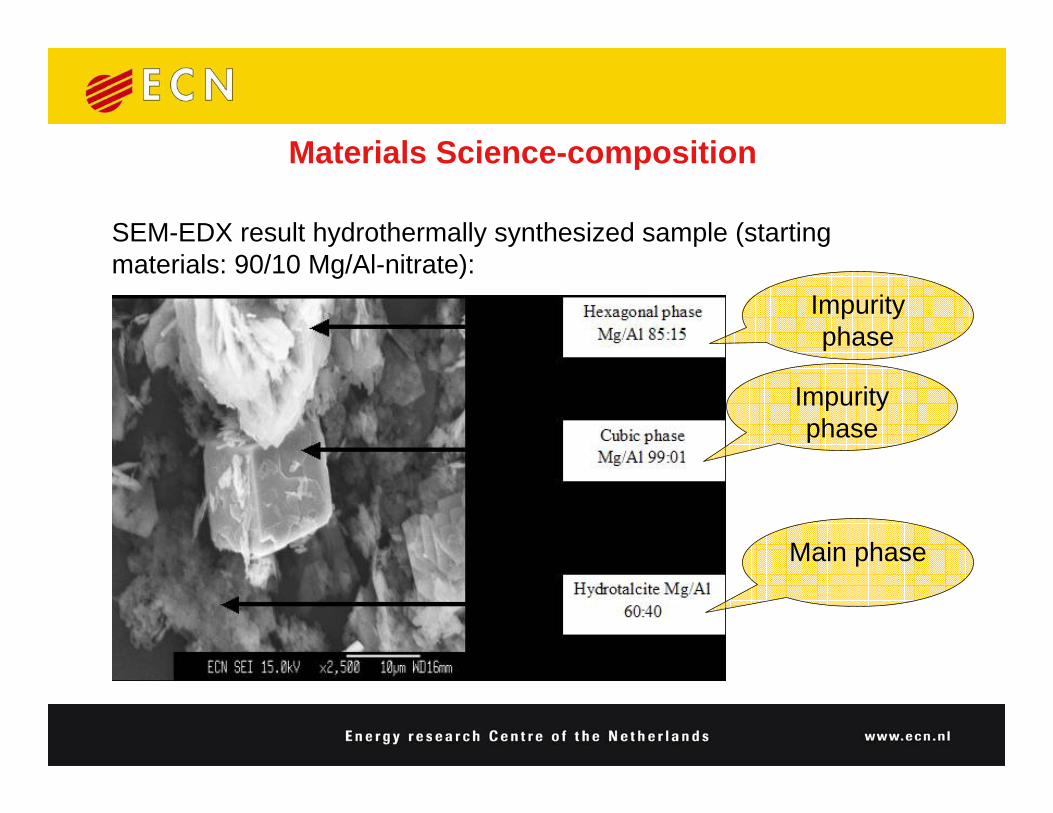
SEM-EDX result hydrothermally synthesized sample (starting materials: 90/10 Mg/Al-nitrate):
Impurity phase
Main phase
Impurity phase
Materials Science-composition

ND very suitable to see
a) Light elements C, O, H
b) Difference between Mg and AlDiffraction experiment on GEM at ISIS, UK
25/75
50/50
90/10
Materials Science-composition

Materials: • Rather poor crystallinity, esp. impurities • 50/50 sample relatively pure: refinable (GSAS)
Results:• Composition Mg0.64Al0.36(OH)2(CO3)0.18·1.0H2O• Mg< 0.64: Boehmite impurity (Al rich)• Mg> 0.64: Hydromagnesite impurity (Mg rich)
Materials Science-composition
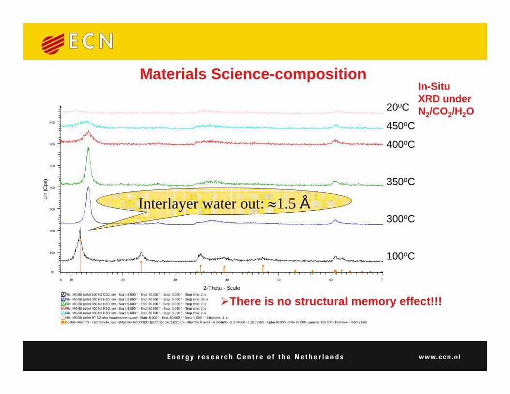
01-089-0460 (C) - Hydrotalcite, syn - (Mg0.667Al0.333)(OH)2(CO3)0.167(H2O)0.5 - Rhombo.H.axes - a 3.04600 - b 3.04600 - c 22.77200 - alpha 90.000 - beta 90.000 - gamma 120.000 - Primitive - R-3m (166)File: MG 50 pellet RT N2 after heattreatments.raw - Start : 5.000 ° - End: 80.000 ° - Step: 0.050 ° - Step time: 4. sFile: MG 50 pellet 450 N2 H2O.raw - Start: 5.000 ° - End: 80.000 ° - Step: 0.050 ° - Step time: 2. sFile: MG 50 pellet 400 N2 H2O.raw - Start: 5.000 ° - End: 80.000 ° - Step: 0.050 ° - Step time: 2. sFile: MG 50 pellet 350 N2 H2O.raw - Start: 5.000 ° - End: 80.000 ° - Step: 0.050 ° - Step time: 2. sFile: MG 50 pellet 300 N2 H2O.raw - Start: 5.000 ° - End: 80.000 ° - Step: 0.050 ° - Step time: 38. sFile: MG 50 pellet 100 N2 CO2.raw - Start: 5.000 ° - End: 80.000 ° - Step: 0.050 ° - Step time: 2. s
Lin
(Cps
)
10
100
200
300
400
500
600
700
2-Theta - Scale8 10 20 30 40 50 60 70
20oC
450oC
400oC
350oC
300oC
100oC
There is no structural memory effect!!!
In-Situ XRD under N2/CO2/H2O
Interlayer water out: ≈1.5 Å
Materials Science-composition

Hydrotalcite TGA/MS
0
10
20
30
0 1000 2000 3000 4000 5000 6000
time (s)
wei
ght (
mg)
-0,002
0,008
0,018
sampleH2OCO2
310°C 450°C100°C 240°C
1. Adsorbed water @100oC
H2O(ad)↔H2O(g)
2. Interlayer water @240oC
H2O(abs)↔H2O(g)
3. Hydroxides @310oC
Mg(OH)2 ↔MgO + H2O(g)
4. Carbonates @450oC
Mg(OH)2 + MgCO3 ↔2MgO +CO2(g) + H2O(g)
First tentative working hypothesis
Materials Science-material stability

Dense membrane produced using cold isostatic pressing under 2000 bar sliced to about 2,4 mm thick discs.• Rest porosity about 15%• Permeancy measured of CO2 and He
Permeancy
1,50
2,50
3,50
4,50
5,50
1,50E-03 2,00E-03 2,50E-03 3,00E-03 3,50E-03
1/T
Ln(F
low
)
HeCO2
• No significant difference between He and CO2(Knudsen-like)
• At 250oC the material deteriorates and permeancy goes up
Materials Science-CO2 transport

Hydrotalcites• Hydrotalcites exist in a small compositional window
around Mg/Al=0.64/0.36=1.8• Hydrotalcites are not stable above 200oC
- dense HTC membranes are not feasible in the T,p window of the applications
- porous HTC membranes not first choice- search for alternative hydroxidic materials or porous supports
impregnated with hydroxidesCatalyst
• Four (pre)commercial pre-reforming catalysts have been tested.• Cheap Ni-catalyst is promising and could do the job in reformers with
CO2 selective membranes.
Materials Science-Conclusions

Reactor Design/System analysis• CO2 selective membranes show a too low CH4 conversion
- driving force for CO2 permeation to low to enhance reform reaction• CO2 selective membranes for WGS give CO conversions comparable to
H2 separating membranes and offer therefore a viable alternative- from efficiency point of view steam sweep should be as low as
possible
Materials Science• Hydrotalcites are not stable above 200oC
- Dense HTC membranes are not feasible in the T,p window of the foreseen applications
- porous HTC membranes not first choice- search for alternative hydroxidic materials or porous supports
impregnated with hydroxides
Summary

Recommended