Advanced Heating & Hot Water Systems
w w w. h t p r o d u c t s. c o m
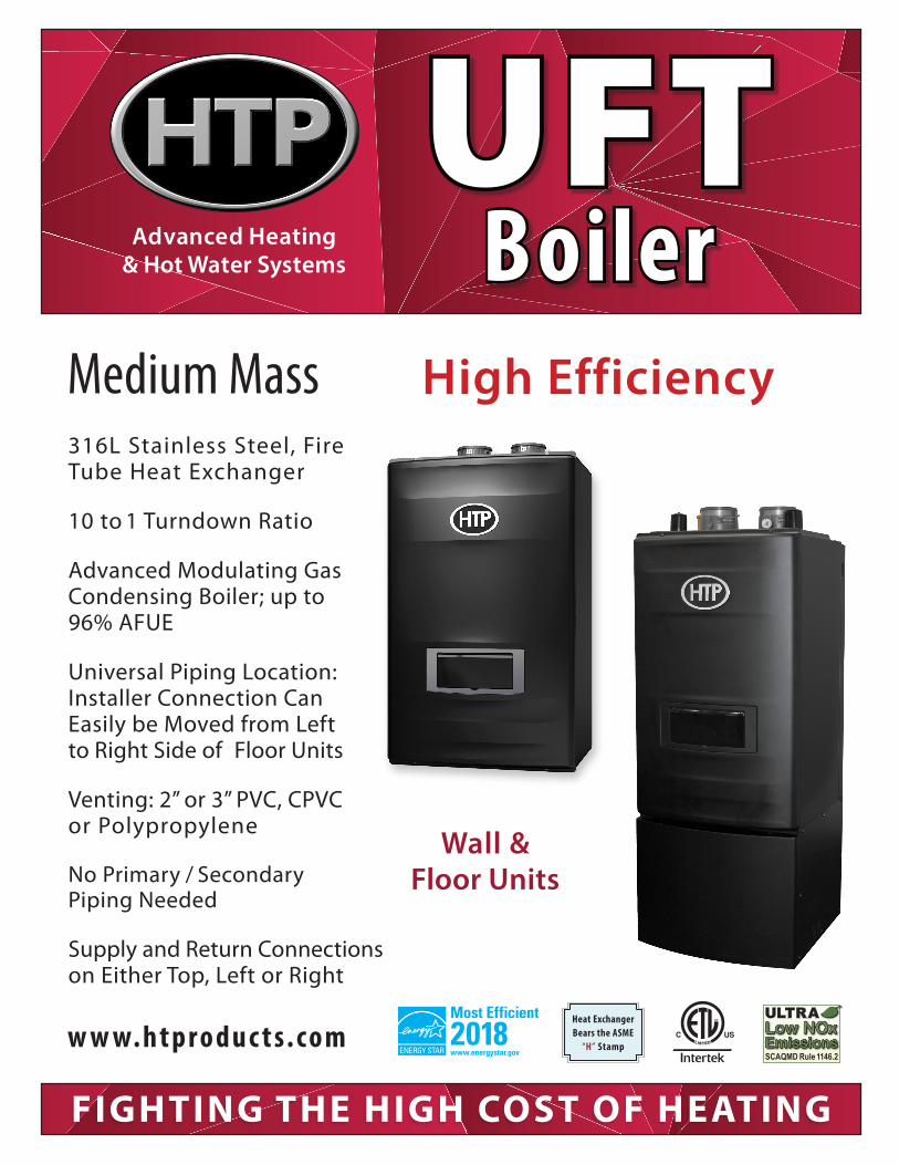
High EfficiencyMedium Mass
FIGHTING THE HIGH COST OF HEATING
2018Heat Exchanger Bears the ASME
“H” StampSCAQMD Rule 1146.2SCAQMD Rule 1146.2
316L Stainless Steel, Fire Tube Heat Exchanger
10 to 1 Turndown Ratio
Advanced Modulating Gas Condensing Boiler; up to 96% AFUE Universal Piping Location: Installer Connection Can Easily be Moved from Left to Right Side of Floor Units
Venting: 2” or 3” PVC, CPVC or Polypropylene
No Primary / Secondary Piping Needed
Supply and Return Connections on Either Top, Left or Right
UFTBoiler
Wall &Floor Units
M U LT I P L E V E N T I N G CO N F I G U R AT I O N S
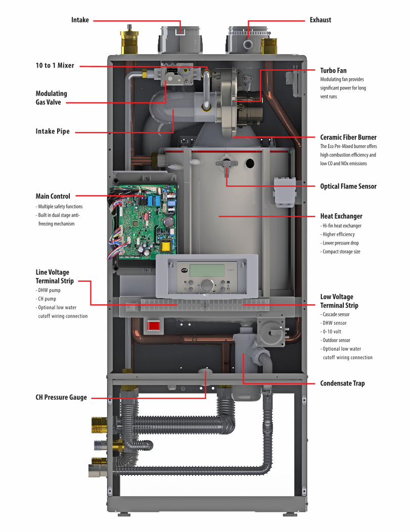
Intake Pipe
10 to 1 Mixer
Modulating Gas Valve
Intake Exhaust
Turbo Fan Modulating fan provides
significant power for long
vent runs
Ceramic Fiber BurnerThe Eco Pre-Mixed burner offers
high combustion efficiency and
low CO and NOx emissions
- Cascade sensor
- DHW sensor
- 0-10 volt
- Outdoor sensor
- Optional low water
cutoff wiring connection
Main Control
Line Voltage Terminal Strip
- Multiple safety functions
- Built in dual stage anti-
freezing mechanism
- DHW pump
- CH pump
- Optional low water
cutoff wiring connection
Condensate Trap
Low Voltage Terminal Strip
CH Pressure Gauge
Heat Exchanger- Hi-fin heat exchanger
- Higher efficiency
- Lower pressure drop
- Compact storage size
Optical Flame Sensor
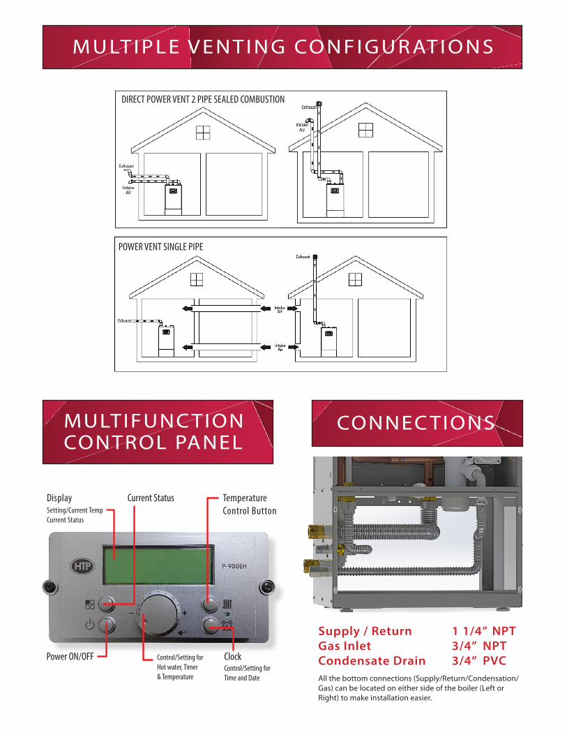
Supply / Return 1 1/4” NPT Gas Inlet 3/4” NPTCondensate Drain 3/4” PVC
M U LT I P L E V E N T I N G CO N F I G U R AT I O N S
DIRECT POWER VENT 2 PIPE SEALED COMBUSTION
POWER VENT SINGLE PIPE
DisplaySetting/Current TempCurrent Status
Power ON/OFF
TemperatureControl Button
Clock Control/Setting for Hot water, Timer & Temperature
Control/Setting for Time and Date All the bottom connections (Supply/Return/Condensation/
Gas) can be located on either side of the boiler (Left or Right) to make installation easier.
Current Status
CONNEC TIONSMULTIFUNC TION CONTROL PANEL
272 Duchaine Blvd, New Bedford, MA 02745 • 1-800-323-9651 • www.htproducts.comMKTLIT- XX - 02/ 2018 © HTP Comfort Solutions LLC.In accordance with our company policy of ongoing product improvement, HTP Comfort Solutions LLC. reserves the right to make changes without prior notice.
G H
A BE F
T
S
Y
U V
W X
R
M N
O P
Q
L K
J I
C
D
A
B
UFT 80-140 FLOOR STAND
DESCRIPTION DIAMETER
A CH SUPPLY ADAPTER 1-1/4" NPT
B CH RETURN ADAPTER 1-1/4" NPT
C GAS INLET ADAPTER 3/4" NPT
D CONDENSATE ADAPTER 1/2" NPT
E INTAKE PIPE CONNECTION 3"
F EXHAUST PIPE CONNECTION 3"
G H
A BE F
T
S
Y
U V
W X
R
M N
O P
Q
L K
J I
C
D
A
B
DESCRIPTION DIAMETER
A CH SUPPLY ADAPTER 1-1/4" NPT
B CH RETURN ADAPTER 1-1/4" NPT
C GAS INLET ADAPTER 3/4" NPT
D CONDENSATE ADAPTER 1/2" NPT
E INTAKE PIPE CONNECTION 3"
F EXHAUST PIPE CONNECTION 3"
G C A B
D
A BE F
Z
G H
A BE F
T
S
Y
U V
W X
R
M N
O P
Q
L K
J I
C
D
A
B
DESCRIPTION DIAMETER
A CH SUPPLY ADAPTER 1-1/4" NPT
B CH RETURN ADAPTER 1-1/4" NPT
C GAS INLET ADAPTER 3/4" NPT
D CONDENSATE ADAPTER 1/2" NPT
E INTAKE PIPE CONNECTION 3"
F EXHAUST PIPE CONNECTION 3"
G C A B
D
A BE F
Z
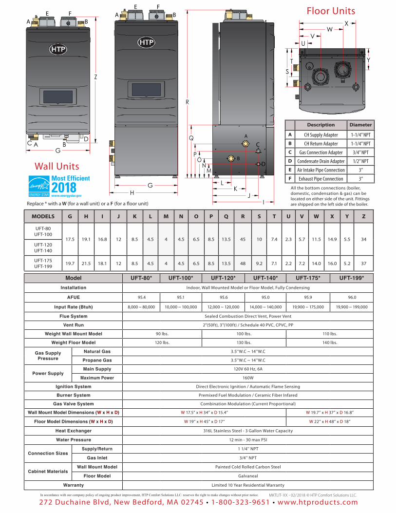
Wall Units
Floor Units
2018
Description Diameter
A CH Supply Adapter 1-1/4” NPT
B CH Return Adapter 1-1/4” NPT
C Gas Connection Adapter 3/4” NPT
D Condensate Drain Adapter 1/2” NPT
E Air Intake Pipe Connection 3”
F Exhaust Pipe Connection 3”
G H
A BE F
T
S
Y
U V
W X
R
M N
O P
Q
L K
J I
C
D
A
B
UFT 80-140 FLOOR STAND
DESCRIPTION DIAMETER
A CH SUPPLY ADAPTER 1-1/4" NPT
B CH RETURN ADAPTER 1-1/4" NPT
C GAS INLET ADAPTER 3/4" NPT
D CONDENSATE ADAPTER 1/2" NPT
E INTAKE PIPE CONNECTION 3"
F EXHAUST PIPE CONNECTION 3"
Replace * with a W (for a wall unit) or a F (for a floor unit)
All the bottom connections (boiler, domestic, condensation & gas) can be located on either side of the unit. Fittings are shipped on the left side of the boiler.
MODELS G H I J K L M N O P Q R S T U V W X Y Z
UFT-80UFT-100
17.5 19.1 16.8 12 8.5 4.5 4 4.5 6.5 8.5 13.5 45 10 7.4 2.3 5.7 11.5 14.9 5.5 34UFT-120UFT-140
UFT-175UFT-199 19.7 21.5 18.1 12 8.5 4.5 4 4.5 6.5 8.5 13.5 48 9.2 7.1 2.2 7.2 14.0 16.0 5.2 37
Model UFT-80* UFT-100* UFT-120* UFT-140* UFT-175* UFT-199*Installation Indoor, Wall Mounted Model or Floor Model, Fully Condensing
AFUE 95.4 95.1 95.6 95.0 95.9 96.0
Input Rate (Btuh) 8,000 ~ 80,000 10,000 ~ 100,000 12,000 ~ 120,000 14,000 ~ 140,000 19,900 ~ 175,000 19,900 ~ 199,000
Flue System Sealed Combustion Direct Vent, Power Vent
Vent Run 2"(50ft), 3"(100ft) / Schedule 40 PVC, CPVC, PP
Weight Wall Mount Model 90 lbs. 100 lbs. 110 lbs.
Weight Floor Model 120 lbs. 130 lbs. 140 lbs.
Gas Supply Pressure
Natural Gas 3.5''W.C ~ 14''W.C
Propane Gas 3.5''W.C ~ 14''W.C
Power SupplyMain Supply 120V 60 Hz, 6A
Maximum Power 160W
Ignition System Direct Electronic Ignition / Automatic Flame Sensing
Burner System Premixed Fuel Modulation / Ceramic Fiber Infared
Gas Valve System Combination Modulation (Current Proportional)
Wall Mount Model Dimensions (W x H x D) W 17.5” x H 34” x D 15.4” W 19.7” x H 37” x D 16.8”
Floor Model Dimensions (W x H x D) W 19” x H 45” x D 17” W 22” x H 48” x D 18”
Heat Exchanger 316L Stainless Steel - 3 Gallon Water Capacity
Water Pressure 12 min - 30 max PSI
Connection SizesSupply/Return 1 1/4'' NPT
Gas Inlet 3/4'' NPT
Cabinet MaterialsWall Mount Model Painted Cold Rolled Carbon Steel
Floor Model Galvaneal
Warranty Limited 10 Year Residential Warranty
Recommended