1 of 1
Addendum No. 1
September 15, 2015
Project: Community Bible Church Addition
Pierre, South Dakota
Architect: Architecture Incorporated
Letting: September 22, 2015
(Closed) 3:00 P.M. Central
Community Bible Church
1516 North Harrison Ave.
Pierre, SD 57501
Scope of this Addendum:
To all bidders and all others to whom drawings and specifications have been issued by Architecture
Incorporated.
Acknowledge receipt of this addendum by listing its number and date in the bidders Form of Proposal.
Failure to do so may subject bidder to disqualification. This Addendum forms a part of the Contract
Documents. It modifies them as follows:
GENERAL ITEMS:
1) INVITATION TO BID
a) Bid Date: Bid Date has been changed to Tuesday, September 29, 2015 at 3:00 P.M. Central
time.
2) SECTION 011000 - SUMMARY:
a) Paragraph 1.5 A. 2: Add: work of Phase 2 shall be substantially complete and ready for
occupancy by March 1, 2017.
b) Paragraph 1.5 A. 3: Add: work of Phase 3 shall be substantially complete and ready for
occupancy by March 1, 2017.
3) SECTION 074113.13 - FORMED METAL ROOF PANELS:
a) Paragraph 2.2 B. 3.: Basis of Design Product:
i) Delete: Bridger Steel 3’ Tuf-Rib 26 Gauge.
ii) Add: Bridger Steel 3’ PBR (Purlin Bearing Rib) 24 Gauge.
b) Paragraph 2.2 B. 4. a.:
i) Delete: Nominal Thickness 0.022 inch; 26 gauge
ii) Add: Nominal Thickness: 24 Gauge.
c) Paragraph 2.2 B. 5.:
i) Delete: Major –rib spacing: 9 inches.
ii) Add: Major-Rib spacing: 12 inches.
d) Paragraph 2.2 B. 7.:
i) Delete: Panel Height: .75 inch.
ii) Add: Panel Height: 1.25 inches.

2 of 1
4) SECTION 074213.13 - FORMED METAL WALL PANELS:
a) Paragraph 2.2 B. 2. c.: Delete “Standard colors”. Color to match “Champagne Metallic” for
reveal panels.
5) SECTION 075323 - EPDM ROOFING:
a) Add Paragraph 2.6.C.:
(a) Cover Board: ASTM C 1177/C 1177M, glass-mat, water-resistant gypsum substrate, [1/4
inch (6 mm)] thick.
(i) Products: Subject to compliance with requirements, [provide the following] [provide
one of the following]:
1. CertainTeed Corporation; [GlasRoc Sheathing].
2. Georgia-Pacific Corporation; [Dens Deck].
3. National Gypsum Company; Gold Bond eXP Extended Exposure Sheathing.
4. USG Corporation; Securock Glass Mat Roof Board.
6) SECTION 087100 - DOOR HARDWARE:
a) Add attached technical specification Section 087100 in it’s entirety.
7) SECTION 084113 - ALUMINUM-FRAMED ENTRANCES AND STOREFRONTS:
a) Paragraph 2.9.A.: Delete “Dark Bronze.” Change anodic finish to “Champagne”.
8) SECTION 084413 - GLAZED ALUMINUM CURTAIN WALLS:
a) Paragraph 2.7.A.: Delete “Dark Bronze.” Change anodic finish to “Champagne”.
9) SECTION 097723 – FABRIC-WRAPPED PANELS:
a) Paragraph 2.1. B.: Delete Plywood core material.
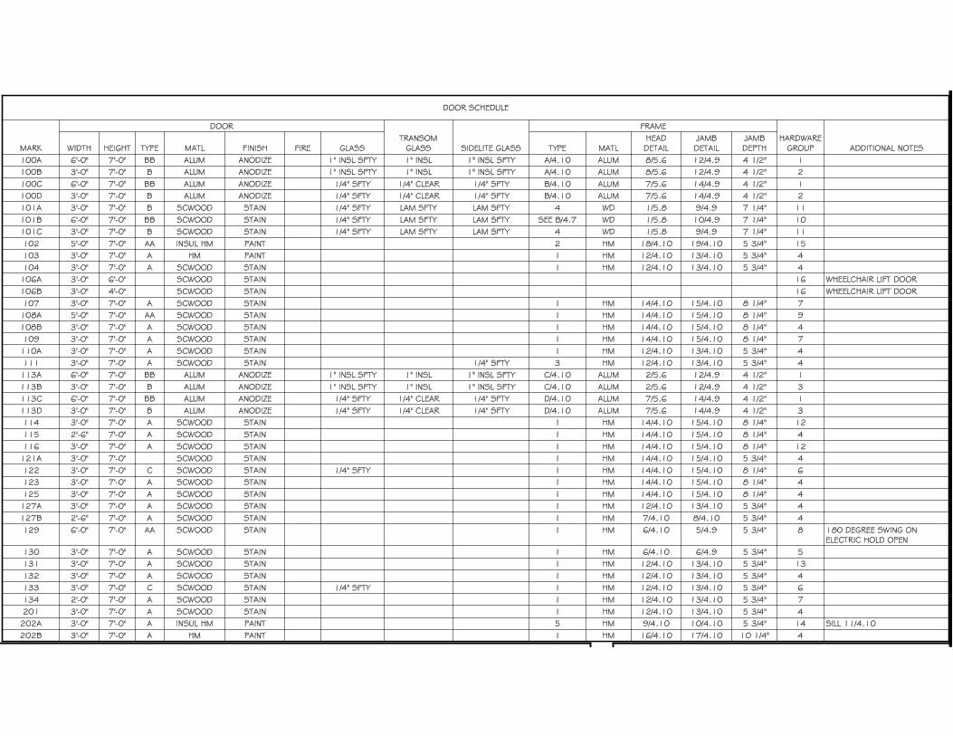
10) DRAWING 4.10 – DOOR SCHEDULE AND DETAILS
a) Door Schedule – See attached revised door schedule with Hardware Groups noted.
GENERAL APPROVALS:
The following material or equipment furnished by the manufacturer's listed, may be substituted as
equivalent providing that each item, material, and piece of equipment conforms to the design and
requirement of the specifications.
SECTION ITEM MANUFACTURER
062023 Interior Finished Carpentry TMi Systems Design Corp.
064214 Stile and Rail Wood Paneling TMi Systems Design Corp.
072100 Thermal Insulation Firestone Enverge
3 of 1
084413 Glazed Aluminum Curtain Walls Manko Windows 250 Series
CMI 6600
097723 Fabric Wrapped Panels G&S Acoustics Acousti-Panels
MECHANICAL ITEMS:
See attached Addendum No. 1 issued by West Plains Engineering.
ELECTRICAL ITEMS:
See attached Addendum No. 1 issued by West Plains Engineering.
END OF ADDENDUM
DOOR HARDWARE 087100 - 1
SECTION 087100 - DOOR HARDWARE
PART 1 - GENERAL
1.1 SUMMARY:
A. Section Includes: Finish Hardware for door openings, except as otherwise specified herein.
1. Door hardware for steel (hollow metal) doors.
2. Door hardware for aluminum doors.
3. Door hardware for wood doors.
4. Door hardware for other doors indicated.
5. Keyed cylinders as indicated.
B. Related Sections:
1. Division 6: Rough Carpentry.
2. Division 8: Aluminum Doors and Frames
3. Division 8: Hollow Metal Doors and Frames.
4. Division 8: Wood Doors.
5. Division 26 Electrical
6. Division 28: Electronic Security
C. References: Comply with applicable requirements of the following standards. Where these standards
conflict with other specific requirements, the most restrictive shall govern.
1. Builders Hardware Manufacturing Association (BHMA)
2. NFPA 101 Life Safety Code
3. NFPA 80 -Fire Doors and Windows
4. ANSI-A156.xx- Various Performance Standards for Finish Hardware
5. UL10C – Positive Pressure Fire Test of Door Assemblies
6. ANSI-A117.1 – Accessible and Usable Buildings and Facilities
7. DHI /ANSI A115.IG – Installation Guide for Doors and Hardware
8. ICC – International Building Code
D. Intent of Hardware Groups
1. Should items of hardware not definitely specified be required for completion of the Work, furnish
such items of type and quality comparable to adjacent hardware and appropriate for service
required.
2. Where items of hardware aren’t definitely or correctly specified, are required for completion of
the Work, a written statement of such omission, error, or other discrepancy to be submitted to
Architect, prior to date specified for receipt of bids for clarification by addendum; or, furnish such
items in the type and quality established by this specification, and appropriate to the service
intended.
E. Allowances
1. Refer to Division 1 for allowance amount and procedures.
F. Alternates
1. Refer to Division 1 for Alternates and procedures.
DOOR HARDWARE 087100 - 2
1.2 SUBSTITUTIONS:
A. Comply with Division 1.
1.3 SUBMITTALS:
A. Comply with Division 1.
B. Special Submittal Requirements: Combine submittals of this Section with Sections listed below to ensure
the "design intent" of the system/assembly is understood and can be reviewed together.
C. Product Data: Manufacturer's specifications and technical data including the following:
1. Detailed specification of construction and fabrication.
2. Manufacturer's installation instructions.
3. Wiring diagrams for each electric product specified. Coordinate voltage with electrical before
submitting.
4. Submit 6 copies of catalog cuts with hardware schedule.
5. Provide 9001-Quality Management and 14001-Environmental Management for products listed in
Materials Section 2.2
D. Shop Drawings - Hardware Schedule: Submit 6 complete reproducible copy of detailed hardware
schedule in a vertical format.
1. List groups and suffixes in proper sequence.
2. Completely describe door and list architectural door number.
3. Manufacturer, product name, and catalog number.
4. Function, type, and style.
5. Size and finish of each item.
6. Mounting heights.
7. Explanation of abbreviations and symbols used within schedule.
8. Detailed wiring diagrams, specially developed for each opening, indicating all electric hardware,
security equipment and access control equipment, and door and frame rough-ins required for
specific opening.
E. Templates: Submit templates and "reviewed Hardware Schedule" to door and frame supplier and others
as applicable to enable proper and accurate sizing and locations of cutouts and reinforcing.
1. Templates, wiring diagrams and "reviewed Hardware Schedule" of electrical terms to electrical
for coordination and verification of voltages and locations.
F. Samples: (If requested by the Architect)
1. 1 sample of Lever and Rose/Escutcheon design, (pair).
2. 3 samples of metal finishes
G. Contract Closeout Submittals: Comply with Division 1 including specific requirements indicated.
1. Operating and maintenance manuals: Submit 3 sets containing the following.
a. Complete information in care, maintenance, and adjustment, and data on repair and
replacement parts, and information on preservation of finishes.
b. Catalog pages for each product.
c. Name, address, and phone number of local representative for each manufacturer.
d. Parts list for each product.
2. Copy of final hardware schedule, edited to reflect, "As installed".
3. Copy of final keying schedule

DOOR HARDWARE 087100 - 3
4. As installed “Wiring Diagrams” for each piece of hardware connected to power, both low voltage
and 110 volts.
5. One set of special tools required for maintenance and adjustment of hardware, including changing
of cylinders.
1.4 QUALITY ASSURANCE
A. Comply with Division 1.
1. Statement of qualification for distributor and installers.
2. Statement of compliance with regulatory requirements and single source responsibility.
3. Distributor's Qualifications: Firm with 3 years experience in the distribution of commercial
hardware.
a. Distributor to employ full time Architectural Hardware Consultants (AHC) for the purpose
of scheduling and coordinating hardware and establishing keying schedule.
b. Hardware Schedule shall be prepared and signed by an AHC.
4. Installer's Qualifications: Firm with 3 years experienced in installation of similar hardware to that
required for this Project, including specific requirements indicated.
5. Regulatory Label Requirements: Provide testing agency label or stamp on hardware for labeled
openings.
a. Provide UL listed hardware for labeled and 20 minute openings in conformance with
requirements for class of opening scheduled.
b. Underwriters Laboratories requirements have precedence over this specification where
conflict exists.
6. Single Source Responsibility: Except where specified in hardware schedule, furnish products of
only one manufacturer for each type of hardware.
B. Review Project for extent of finish hardware required to complete the Work. Where there is a conflict
between these Specifications and the existing hardware, notify the Architect in writing and furnish
hardware in compliance with the Specification unless otherwise directed in writing by the Architect.
1.5 DELIVERY, STORAGE, AND HANDLING
A. Packing and Shipping: Comply with Division 1.
1. Deliver products in original unopened packaging with legible manufacturer's identification.
2. Package hardware to prevent damage during transit and storage.
3. Mark hardware to correspond with "reviewed hardware schedule".
4. Deliver hardware to door and frame manufacturer upon request.
B. Storage and Protection: Comply with manufacturer's recommendations.
1.6 PROJECT CONDITIONS:
A. Coordinate hardware with other work. Furnish hardware items of proper design for use on doors and
frames of the thickness, profile, swing, security and similar requirements indicated, as necessary for the
proper installation and function, regardless of omissions or conflicts in the information on the Contract
Documents.
B. Review Shop Drawings for doors and entrances to confirm that adequate provisions will be made for the
proper installation of hardware.

DOOR HARDWARE 087100 - 4
1.7 WARRANTY:
A. Refer to Conditions of the Contract
B. Manufacturer’s Warranty:
1. Closers: Ten years
2. Exit Devices: Five Years
3. Locksets & Cylinders: Three years
4. All other Hardware: Two years.
1.8 OWNER’S INSTRUCTION:
A. Instruct Owner’s personnel in operation and maintenance of hardware units.
1.9 MAINTENANCE:
A. Extra Service Materials: Deliver to Owner extra materials from same production run as products
installed. Package products with protective covering and identify with descriptive labels. Comply with
Division 1 Closeout Submittals Section.
1. Special Tools: Provide special wrenches and tools applicable to each different or special hardware
component.
2. Maintenance Tools: Provide maintenance tools and accessories supplied by hardware component
manufacturer.
3. Delivery, Storage and Protection: Comply with Owner’s requirements for delivery, storage and
protection of extra service materials.
B. Maintenance Service: Submit for Owner’s consideration maintenance service agreement for electronic
products installed.
C.
PART 2 - PRODUCTS
2.1 MANUFACTURERS:
A. The following manufacturers are approved subject to compliance with requirements of the Contract
Documents. Approval of manufacturers other than those listed shall be in accordance with Division 1.
Item: Manufacturer: Approved:
Hinges Stanley Hager, Bommer
Continuous Hinges Stanley ABH, Roton
Locksets Stanley QCL200 Schlage
Cylinders Match Existting Match Existing
Exit Devices Stanley QED100 Von Duprin
Closers Stanley QCL200 LCN
Automatic Operators Stanley D-4990 No substitution
Push/Pull Plates Hager Burns, Rockwood
Push/Pull Bars Hager Burns, Rockwood
Protection Plates Hager Burns, Rockwood
Overhead Stops ABH Rockwood, Ives
Door Stops Hager Rockwood, Ives
Flush Bolts Hager Burns, Rockwood
Coordinator & Brackets Hager Burns, DCI
Threshold & Gasketing Pemko Hager, Reese
DOOR HARDWARE 087100 - 5
2.2 MATERIALS:
A. Hinges: Shall be Five Knuckle Ball bearing hinges
1. Template screw hole locations
2. Bearings are to be fully hardened.
3. Bearing shell is to be consistent shape with barrel.
4. Minimum of 2 permanently lubricated non-detachable bearings on standard weight hinge and 4
permanently lubricated bearing on heavy weight hinges.
5. Equip with easily seated, non-rising pins.
6. Non Removable Pin screws shall be slotted stainless steel screws.
7. Hinges shall be full polished, front, back and barrel.
8. Hinge pin is to be fully plated.
9. Bearing assembly is to be installed after plating.
10. Sufficient size to allow 180-degree swing of door
11. Furnish five knuckles with flush ball bearings
12. Provide hinge type as listed in schedule.
13. Furnish 3 hinges per leaf to 7 foot 6 inch height. Add one for each additional 30 inches in height
or fraction thereof.
14. Tested and approved by BHMA for all applicable ANSI Standards for type, size, function and
finish
15. UL10C listed for Fire rated doors.
B. Geared Continuous Hinges:
1. Tested and approved by BHMA for ANSI A156.26-1996 Grade 1
2. Anti-spinning through fastener
3. UL10C listed for 3 hour Fire rating
4. Non-handed
5. Lifetime warranty
6. Provide Fire Pins for 3-hour fire ratings
7. Sufficient size to permit door to swing 180 degrees
C. Cylindrical Type Locks and Latchsets:
1. Tested and approved by BHMA for ANSI A156.2, Series 4000, Operational Grade 2, Heavy
Duty, and be UL10C listed.
2. Provide 9001-Quality Management and 14001-Environmental Management.
3. Fit modified ANSI A115.2 door preparation.
4. Locksets and cores to be of the same manufacturer to maintain complete lockset warranty
5. Locksets to have anti-rotational studs that are thru-bolted
6. Keyed lever shall not have exposed “keeper” hole
7. Each lever to have independent spring mechanism controlling it
8. 2-3/4 inch (70 mm) backset
9. 9/16 inch (14 mm) throw latchbolt
10. Provide sufficient curved strike lip to protect door trim
11. Outside lever sleeve to be seamless, of one-piece construction made of a hardened steel alloy
12. Provide locksets with 6-pin core to match existing system
13. Hub, side plate, shrouded rose, locking pin to be a one-piece casting with a shrouded locking lug.
14. Core face must be the same finish as the lockset.
15. Functions and design as indicated in the hardware groups.
D. Cylindrical Deadbolt:
1. Tested and approved by ANSI A156.5, Operational Grade 1,

DOOR HARDWARE 087100 - 6
2. Fit modified ANSI A115.3 door preparation
3. Provide 9001-Quality Management and 14001-Environmental Management.
4. Locksets and cores to be of the same manufacturer to maintain complete lockset warranty
5. 2-3/4 inch (70mm) backset, or 2 3/8 inch backset as needed
6. 1 inch throw deadbolt
7. Provide locksets with 7-pin core.
8.
E. Exit Devices shall:
1. Tested and approved by BHMA for ANSI 156.3, Grade 1
2. Provide 9001-Quality Management and 14001-Environmental Management.
3. Furnish UL or recognized independent laboratory certified mechanical operational testing to 9
million cycles minimum.
4. Provide a deadlocking latchbolt
5. Non-fire rated exit devices shall have cylinder dogging.
6. Touchpad shall be “T” style
7. Exposed components shall be of architectural metals and finishes.
8. Lever design shall match lockset lever design
9. Provide strikes as required by application.
10. Fire exit devices to be listed for UL10C
11. UL listed for Accident Hazard
12. Shall consist of a cross bar or push pad, the actuating portion of which extends across, shall not be
less than one half the width of the door leaf.
13. Provide vandal resistant or breakaway trim
F. Cylinders:
1. Provide the necessary cylinder housings, collars, rings & springs as recommended by the
manufacturer for proper installation.
2. Provide the proper cylinder cams or tail piece as required to operate all locksets and other keyed
hardware items listed in the hardware sets.
3. Coordinate and provide as required for related sections.
G. Door Closers shall:
1. Tested and approved by BHMA for ANSI 156.4, Grade 1 or Grade per shedule
2. UL10C certified
3. Provide 9001-Quality Management and 14001-Environmental Management.
4. Closer shall have extra-duty arms and knuckles
5. Conform to ANSI 117.1
6. Maximum 2 7/16 inch case projection with non-ferrous cover
7. Separate adjusting valves for closing and latching speed, and backcheck
8. Provide adapter plates, shim spacers and blade stop spacers as required by frame and door
conditions
9. Full rack and pinion type closer with 1½“ minimum bore
10. Mount closers on non-public side of door, unless otherwise noted in specification
11. Closers shall be non-handed, and multi-sized.
2.3 FINISH:
A. Designations used in Schedule of Finish Hardware - 3.5, and elsewhere to indicate hardware finishes are
those listed in ANSI/BHMA A156.18 including coordination with traditional U.S. finishes shown by
certain manufacturers for their products
B. Powder coat door closers to match other hardware, unless otherwise noted.

DOOR HARDWARE 087100 - 7
C. Aluminum items shall be finished to match predominant adjacent material. Seals to coordinate with
frame color.
2.4 KEYS AND KEYING:
A. Provide keyed brass cores and keys. Permanent cores and keys (prepared according to the accepted
keying schedule) will be furnished to the Owner.
B. Cylinders, 6-pin, Match existing Keyway.
C. Permanent keys and cores: Stamped with the applicable key mark for identification. Permanent keys will
also be stamped "Do Not Duplicate."
D. Transmit Masterkeys and other Security keys to Owner by Registered Mail, return receipt requested.
E. Furnish keys in the following quantities:
1. 2 each Masterkeys
2. 2 each Change keys each keyed core
F. Keying Schedule: Arrange for a keying meeting, with Architect/Owner and hardware supplier, and other
involved parties to ensure locksets and locking hardware, are functionally correct and keying complies
with project requirements. Furnish 1 typed copies of keying schedule to Architect.
PART 3 - EXECUTION
3.1 EXAMINATION
A. Verification of conditions: Examine doors, frames, related items and conditions under which Work is to
be performed and identify conditions detrimental to proper and or timely completion.
1. Do not proceed until unsatisfactory conditions have been corrected.
3.2 HARDWARE LOCATIONS:
A. Mount hardware units at heights indicated in the following publications except as specifically indicated
or required to comply with the governing regulations.
1. Recommended Locations for Builder’s Hardware for Standard Steel Doors and Frames, by the
Door and Hardware Institute (DHI).
2. Recommended locations for Architectural Hardware for flush wood doors (DHI).
3. WDMA Industry Standard I.S.-1A-04, Industry Standard for Architectural wood flush doors.
3.3 INSTALLATION:
A. Install each hardware item per manufacturer's instructions and recommendations. Do not install surface
mounted items until finishes have been completed on the substrate. Set units level, plumb and true to
line and location. Adjust and reinforce the attachment substrate as necessary for proper installation and
operation.
B. Conform to local governing agency security ordinance.
C. Install Conforming to ICC/ANSI A117.1 Accessible and Usable Building and Facilities.

DOOR HARDWARE 087100 - 8
1. Adjust door closer sweep periods so that from the open position of 70 degrees, the door will take
at least 3 seconds to move to a point 3 inches from the latch, measured to the landing side of the
door.
D. Installed hardware using the manufacturers fasteners provided. Drill and tap all screw holes located in
metallic materials. Do not use “Riv-Nuts” or similar products.
3.4 FIELD QUALITY CONTROL AND FINAL ADJUSTMENT
A. Contractor/Installers, Field Services: After installation is complete, contractor shall inspect the
completed door openings on site to verify installation of hardware is complete and properly adjusted, in
accordance with both the Contract Documents and final shop drawings.
1. Check and adjust closers to ensure proper operation.
2. Check latchset, lockset, and exit devices are properly installed and adjusted to ensure proper
operation.
a. Verify levers are free from binding.
b. Ensure latchbolts and dead bolts are engaged into strike and hardware is functioning.
3. Report findings, in writing, to architect indicating that all hardware is installed and functioning
properly. Include recommendations outlining corrective actions for improperly functioning
hardware if required.
3.5 SCHEDULE OF FINISH HARDWARE:
Hardware Group 1 (Exterior & Vestibule Aluminum Pairs 100A, 100C, 113A, 113C)
Each Opening
Continuous Hinges By Aluminum Door Supplier
Door Closers-Heavy duty arm By Aluminum Door Supplier
Exit Devices By Aluminum Door Supplier
Threshold and Door Sweeps By Aluminum Door Supplier
Weather-strip and door meeting seals By Aluminum Door Supplier
2 Cylinders keyed to System Stanley Rim/Mortise as needed by Exit devices
Hardware Group 2 (Exterior & Vestibule Aluminum Singles with operator (100B, 100D)
2 Continuous Hinges By Aluminum Door Supplier
2 Exit Devices By Aluminum Door Supplier
2 Electric Strikes Adam Rite 74R2 x 12/24VDC
Automatic Operator Stanley D4990 x 689
2 Push Pads (6” round-Handicap) WIKK
3 Bollards WIKK
1 Vestibule Double Push Pad with arrows WIKK
1 Key Switch RCI
Threshold and Door Sweeps By Aluminum Door Supplier
Weather-strip and door meeting seals By Aluminum Door Supplier
2 Cylinders keyed to System Stanley Rim/Mortise as needed by deadbolts

DOOR HARDWARE 087100 - 9
Hardware Group 3 (Exterior & Vestibule Aluminum Singles with operator (113B, 113D)
Each Opening
Continuous Hinge By Aluminum Door Supplier
Door Closer-Heavy duty arm By Aluminum Door Supplier
Exit Device By Aluminum Door Supplier
Threshold and Door Sweeps By Aluminum Door Supplier
Weather-strip and door meeting seals By Aluminum Door Supplier
1 Cylinders keyed to System Stanley Rim/Mortise as needed by Exit device
Hardware Group 4 (Single Interior Wood Door x HM Frame x Office/Entry Lock: 103, 104, 108B, 110A, 111,
115, 121A, 123, 125, 127A, 127B, 132, 201, 202B) (HM Door at 103)
Each Opening:
Hinges Stanley (3) FBB179 x 4 ½” x 4 ½” x US26D
Cylindrical Lock-Office/Entry function Stanley (1) QCL250 x E x US26D
Wall Stop Hager (1) 236W x US32D
Overhead Stop (omit wall stop) ABH (1) 4423 x 630 (104, 110A, 115, 125, 202B only)
Smoke/Sound Seal Pemko (1) S88D x 17 ft
Hardware Group 5 (90 Minute Single Interior Wood Door x HM Frame x Office/Entry Lock: 130)
Each Opening:
Hinges Stanley (3) FBB179 x 4 ½” x 4 ½” x US26D
Door Closer Stanley (1) Stanley QDC211 x SN x 689
Cylindrical Lock-Office/Entry function Stanley (1) QCL250 x E x US26D
Smoke/Sound Seal Pemko (1) S88D x 17 ft
Hardware Group 6 (Single Interior Wood Door x HM Frame x Classroom Lock: 122, 133)
Each Opening:
Hinges Stanley (3) FBB179 x 4 ½” x 4 ½” x US26D
Cylindrical Lock-Classroom function Stanley (1) QCL260 x E x US26D
Wall Stop Hager (1) 236W x US32D @122 only
Overhead Stop ABH (1) ABH 4423 x US32D @ 133 only
Smoke/Sound Seal Pemko (1) S88D x 17 ft
Hardware Group 7 (Single Interior Wood Door x HM Frame x Passage Lever: 107, 109, 134)
Each Opening:
Hinges Stanley (3) FBB179 x 4 ½” x 4 ½” x US26D
Cylindrical Lever-Passage function Stanley (1) QCL230 x E x US26D
Overhead Stop ABH (1) ABH 4423 x US32D
Smoke/Sound Seal Pemko (1) S88D x 17 ft
Hardware Group 8 (Pair Interior Wood Doors x HM Frame x 90 Minute Rated (129)
Each Opening:
Hinges Stanley (6) FBB179 x 4 ½” x 4 ½” x US26D
Door Closer Stanley (2) Stanley QDC211 x SN x 689
Rim Exit Devices Stanley (2) QED113 x QET160 x E x US32D
Removable Mullion-Key removable Stanley (1) QRM113KR x 689
2 Cylinders keyed to System Stanley (2) Rim Cylinders x US26D
Smoke/Sound Seal Pemko (1) S88D x 20 ft (frame)
Smoke/Sound Seal Pemko (2) S44D x 7 ft (for mullion)
DOOR HARDWARE 087100 - 10
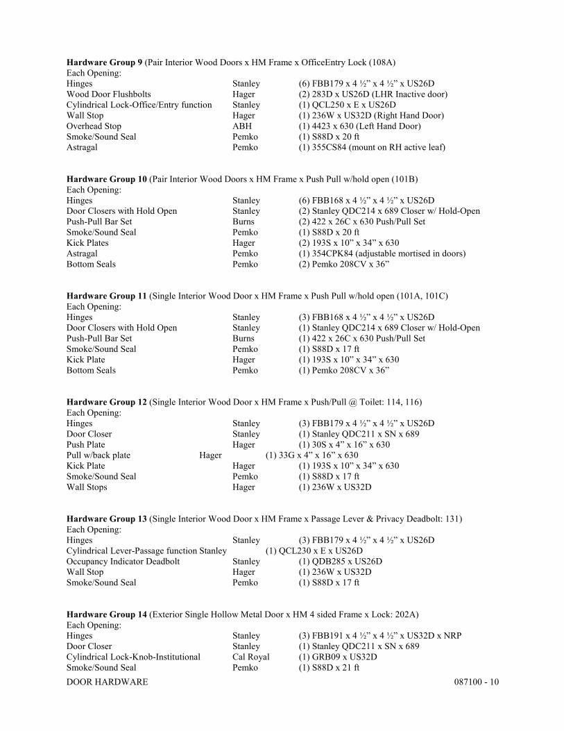
Hardware Group 9 (Pair Interior Wood Doors x HM Frame x OfficeEntry Lock (108A)
Each Opening:
Hinges Stanley (6) FBB179 x 4 ½” x 4 ½” x US26D
Wood Door Flushbolts Hager (2) 283D x US26D (LHR Inactive door)
Cylindrical Lock-Office/Entry function Stanley (1) QCL250 x E x US26D
Wall Stop Hager (1) 236W x US32D (Right Hand Door)
Overhead Stop ABH (1) 4423 x 630 (Left Hand Door)
Smoke/Sound Seal Pemko (1) S88D x 20 ft
Astragal Pemko (1) 355CS84 (mount on RH active leaf)
Hardware Group 10 (Pair Interior Wood Doors x HM Frame x Push Pull w/hold open (101B)
Each Opening:
Hinges Stanley (6) FBB168 x 4 ½” x 4 ½” x US26D
Door Closers with Hold Open Stanley (2) Stanley QDC214 x 689 Closer w/ Hold-Open
Push-Pull Bar Set Burns (2) 422 x 26C x 630 Push/Pull Set
Smoke/Sound Seal Pemko (1) S88D x 20 ft
Kick Plates Hager (2) 193S x 10” x 34” x 630
Astragal Pemko (1) 354CPK84 (adjustable mortised in doors)
Bottom Seals Pemko (2) Pemko 208CV x 36”
Hardware Group 11 (Single Interior Wood Door x HM Frame x Push Pull w/hold open (101A, 101C)
Each Opening:
Hinges Stanley (3) FBB168 x 4 ½” x 4 ½” x US26D
Door Closers with Hold Open Stanley (1) Stanley QDC214 x 689 Closer w/ Hold-Open
Push-Pull Bar Set Burns (1) 422 x 26C x 630 Push/Pull Set
Smoke/Sound Seal Pemko (1) S88D x 17 ft
Kick Plate Hager (1) 193S x 10” x 34” x 630
Bottom Seals Pemko (1) Pemko 208CV x 36”
Hardware Group 12 (Single Interior Wood Door x HM Frame x Push/Pull @ Toilet: 114, 116)
Each Opening:
Hinges Stanley (3) FBB179 x 4 ½” x 4 ½” x US26D
Door Closer Stanley (1) Stanley QDC211 x SN x 689
Push Plate Hager (1) 30S x 4” x 16” x 630
Pull w/back plate Hager (1) 33G x 4” x 16” x 630
Kick Plate Hager (1) 193S x 10” x 34” x 630
Smoke/Sound Seal Pemko (1) S88D x 17 ft
Wall Stops Hager (1) 236W x US32D
Hardware Group 13 (Single Interior Wood Door x HM Frame x Passage Lever & Privacy Deadbolt: 131)
Each Opening:
Hinges Stanley (3) FBB179 x 4 ½” x 4 ½” x US26D
Cylindrical Lever-Passage function Stanley (1) QCL230 x E x US26D
Occupancy Indicator Deadbolt Stanley (1) QDB285 x US26D
Wall Stop Hager (1) 236W x US32D
Smoke/Sound Seal Pemko (1) S88D x 17 ft
Hardware Group 14 (Exterior Single Hollow Metal Door x HM 4 sided Frame x Lock: 202A)
Each Opening:
Hinges Stanley (3) FBB191 x 4 ½” x 4 ½” x US32D x NRP
Door Closer Stanley (1) Stanley QDC211 x SN x 689
Cylindrical Lock-Knob-Institutional Cal Royal (1) GRB09 x US32D
Smoke/Sound Seal Pemko (1) S88D x 21 ft

DOOR HARDWARE 087100 - 11
Hardware Group 15 (Pair Exterior Hollow Metal Doors x HM Frame (102)
Each Opening:
Hinges Stanley (6) FBB191 x 4 ½” x 4 ½” x US32D x NRP
Door Closer Stanley (2) Stanley QDC211 x SN x 689
Rim Exit Devices Stanley (2) QED111 x QET160 x E x US32D
Removable Mullion-Key removable Stanley (1) QRM113KR x 689
2 Cylinders keyed to System Stanley (2) Rim Cylinders x US26D
Weatherstrip Pemko (2) 303AS x 36” x 84”
Sweeps Pemko (2) 315CN x 36”
Threshold Pemko (1) 171A x 72”
Hardware Group 16 (Single Interior Wood Door x HM Frame x Electric Strike: 106A, 106B)
Each Opening:
Hinges Stanley (3) FBB179 x 4 ½” x 4 ½” x US26D @ 106A
Hinges Stanley (2) FBB179 x 4 ½” x 4 ½” x US26D @ 106B
Pull opposite elevator Platform Hager (1) 3G x US32D
Gate Latch Cal Royal (1) GL220 x US26D
Electric Strike RCI (1) #4 x US32D (Verify voltage with Elevator
provider before ordering
Interior Flush Pull Hager (1) 17N x US26D
END OF SECTION
1750 Rand Road Rapid City, SD 57702 Ph: (605) 348-7455 Fax (605) 348-9445
RAPID CITY
ADDENDUM #1
RAPID CITY, SD SIOUX FALLS, SD CASPER, WY CEDAR RAPIDS, IA BISMARCK, ND
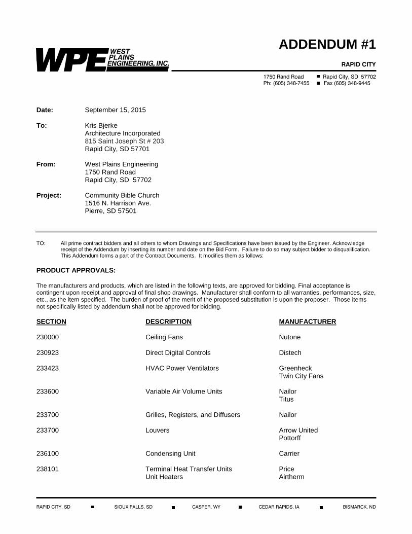
Date: September 15, 2015 To: Kris Bjerke Architecture Incorporated 815 Saint Joseph St # 203 Rapid City, SD 57701 From: West Plains Engineering 1750 Rand Road Rapid City, SD 57702 Project: Community Bible Church 1516 N. Harrison Ave. Pierre, SD 57501 TO: All prime contract bidders and all others to whom Drawings and Specifications have been issued by the Engineer. Acknowledge
receipt of the Addendum by inserting its number and date on the Bid Form. Failure to do so may subject bidder to disqualification. This Addendum forms a part of the Contract Documents. It modifies them as follows:
PRODUCT APPROVALS: The manufacturers and products, which are listed in the following texts, are approved for bidding. Final acceptance is contingent upon receipt and approval of final shop drawings. Manufacturer shall conform to all warranties, performances, size, etc., as the item specified. The burden of proof of the merit of the proposed substitution is upon the proposer. Those items not specifically listed by addendum shall not be approved for bidding. SECTION DESCRIPTION MANUFACTURER 230000 Ceiling Fans Nutone 230923 Direct Digital Controls Distech 233423 HVAC Power Ventilators Greenheck Twin City Fans 233600 Variable Air Volume Units Nailor Titus 233700 Grilles, Registers, and Diffusers Nailor 233700 Louvers Arrow United Pottorff 236100 Condensing Unit Carrier 238101 Terminal Heat Transfer Units Price Unit Heaters Airtherm
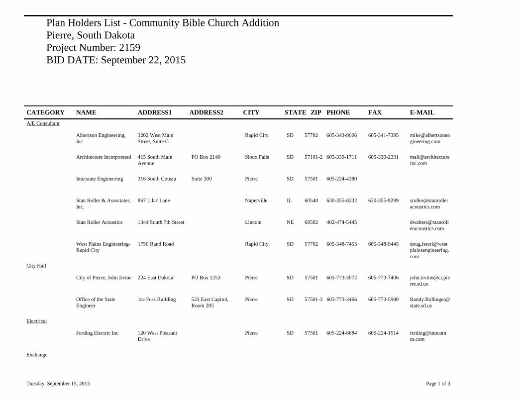
Plan Holders List - Community Bible Church Addition
Pierre, South Dakota
Project Number: 2159
BID DATE: September 22, 2015
CATEGORY NAME ADDRESS1 ADDRESS2 CITY STATE ZIP PHONE FAX E-MAIL
A/E Consultant
Albertson Engineering,
Inc
3202 West Main
Street, Suite C
Rapid City SD 57702 605-343-9606 605-341-7395 mike@albertsonen
gineering.com
Architecture Incorporated 415 South Main
Avenue
PO Box 2140 Sioux Falls SD 57101-2 605-339-1711 605-339-2331 mail@architecture
inc.com
Interstate Engineering 316 South Coteau Suite 300 Pierre SD 57501 605-224-4380
Stan Roller & Associates,
Inc.
867 Lilac Lane Naperville IL 60540 630-355-8232 630-355-9299 sroller@stanroller
acoustics.com
Stan Roller Acoustics 1344 South 7th Street Lincoln NE 68502 402-474-5445 dwalters@stanroll
eracoustics.com
West Plains Engineering-
Rapid City
1750 Rand Road Rapid City SD 57702 605-348-7455 605-348-9445 doug.feterl@west
plainsengineering.
com
City Hall
City of Pierre, John Irvine 224 East Dakota` PO Box 1253 Pierre SD 57501 605-773-3072 605-773-7406 [email protected]
rre.sd.us
Office of the State
Engineer
Joe Foss Building 523 East Capitol,
Room 205
Pierre SD 57501-3 605-773-3466 605-773-5980 Randy.Bollinger@
state.sd.us
Electrical
Ferding Electric Inc 120 West Pleasant
Drive
Pierre SD 57501 605-224-8684 605-224-1514 ferding@mncom
m.com
Exchange
Tuesday, September 15, 2015 Page 1 of 3

CATEGORY NAME ADDRESS1 ADDRESS2 CITY STATE ZIP PHONE FAX E-MAIL
Aberdeen Builders
Exchange
302 North Jackson
Street
Aberdeen SD 57401 605-225-4733 dakotabuild@mid
conetwork.com
CMD Group 30 Technology
Parkway South
Suite 100 Norcross GA 30092 addenda@reedbus
iness.com
Construction Industry
Center, Inc.
2771 Plant Street Rapid City SD 57709 605-343-5252 605-343-4591 cic@constructioni
ndustrycenter.com
Construction Plans
Exchange
215 Airport Road Bismark ND 58504 701-258-4215 701-258-1391 cpeinc@midconet
work.com
Dodge Data and Analytics 7265 Kenwood Road Suite 200 Cincinnati OH 45236 501-851-1438 501-851-9534 dodge_reocmw@c
onstruction.com
Fargo-Moorhead Builders
Exchange
1010 Page Drive Fargo ND 58106 701-237-6772 701-232-1653 [email protected]
Lincoln Builders Bureau 5910 South 58th Street Suite C Lincoln NE 68516 402-421-8332 402-421-8334 builders@cornhus
ker.net
Minnesota Builders
Exchange
1123 Glenwood
Avenue
Minneapolis MN 55405 612-381-2620 612-381-2621 [email protected]
rg
Omaha Builders Exchange 4255 South 94th Street Omaha NE 68127 402-593-6908 402-593-6912 omahaplanroom-
om
Plains Builders Exchange 220 North Kiwanis
Avenue
Sioux Falls SD 57104 605-334-8886 605-334-0112 info@plainsbuilde
rs.com
Sioux City Construction
League
3900 Stadium Drive Sioux City IA 51102 712-255-9730 712-255-3915 scplanroom@siou
xlan.net
Sioux Falls Builders
Exchange
1418 C Avenue Sioux Falls SD 57104 605-357-8687 605-357-8655 [email protected]
General Contractor
First Dakota Enterprises 1223 Sale Barn PO Box 910 Fort Pierre SD 57532 605-223-9600 605-223-2045 Slade.weller@first
dakotaenterprises.
com
Gil Haugan Construction,
Inc.
200 East 60th Street
North
Sioux Falls SD 57104 605-336-6082 605-336-0051 [email protected]
om
Midwest Construction Inc 740 East Sioux Avenue PO Box 489 Pierre SD 57501 605-224-6345 605-224-9151 www.zmidwest.co
m
Tuesday, September 15, 2015 Page 2 of 3
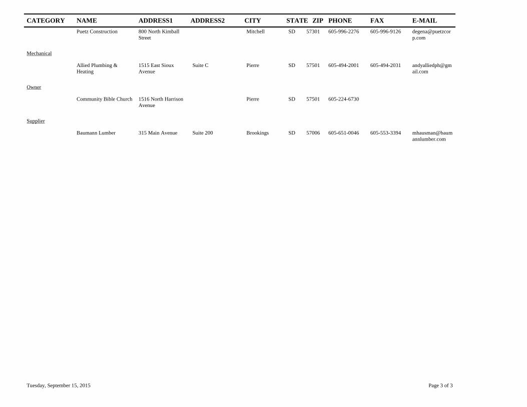
CATEGORY NAME ADDRESS1 ADDRESS2 CITY STATE ZIP PHONE FAX E-MAIL
Puetz Construction 800 North Kimball
Street
Mitchell SD 57301 605-996-2276 605-996-9126 degena@puetzcor
p.com
Mechanical
Allied Plumbing &
Heating
1515 East Sioux
Avenue
Suite C Pierre SD 57501 605-494-2001 605-494-2031 andyalliedph@gm
ail.com
Owner
Community Bible Church 1516 North Harrison
Avenue
Pierre SD 57501 605-224-6730
Supplier
Baumann Lumber 315 Main Avenue Suite 200 Brookings SD 57006 605-651-0046 605-553-3394 mhausman@baum
annlumber.com
Tuesday, September 15, 2015 Page 3 of 3
Recommended