Achieve Proficiency in Facilities Validations
Agenda • Facilities Validation Overview
– Purpose – Facility and Utility Lifecycle Management – Qualification Stages, Impact to Product and Risk Level
• Types of Facilities Validations – Architectural Finishes, Cleanroom Performance, HVAC, CDA, FMS – Outputs applicable per type
• Documenting Facilities Validations
– Protocol and Report Requirements – Deviations
• Maintain the Validated State
– Controls and Change management
• Interactive Exercise – Experiences and lessons learned
Purpose of Facilities Validations
• Guarantee that facility and utility systems are qualified as intended for manufacturing medical devices that meet specifications
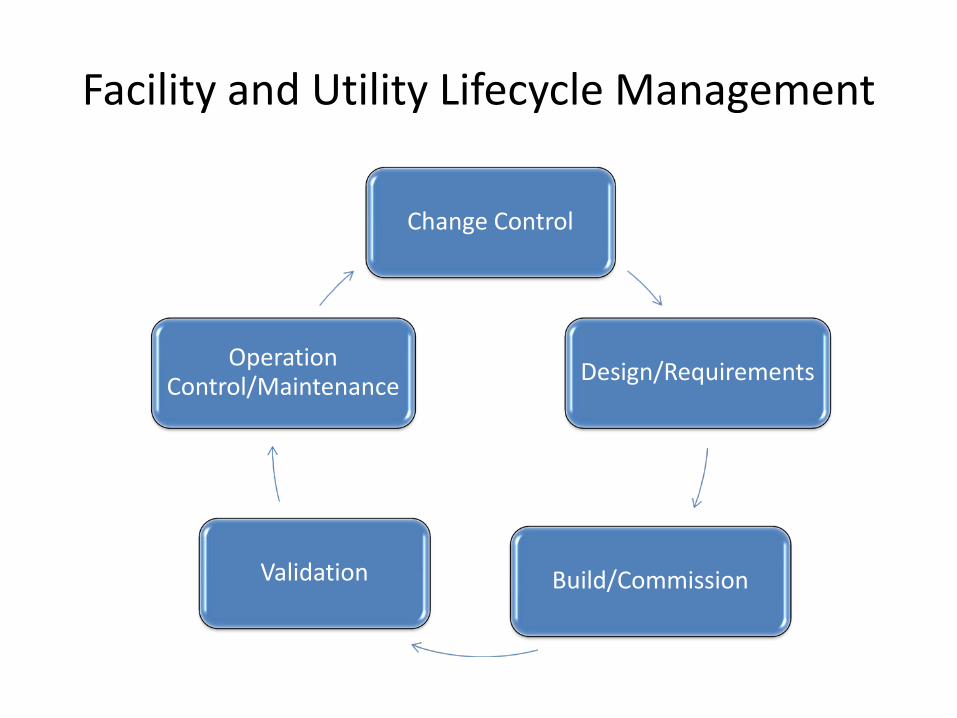
Facility and Utility Lifecycle Management
Change Control
Design/Requirements
Build/Commission Validation
Operation Control/Maintenance
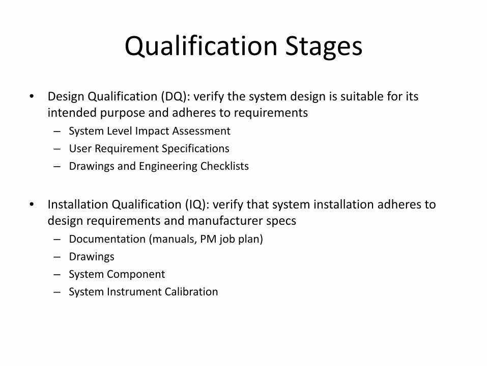
Qualification Stages • Design Qualification (DQ): verify the system design is suitable for its
intended purpose and adheres to requirements – System Level Impact Assessment – User Requirement Specifications – Drawings and Engineering Checklists
• Installation Qualification (IQ): verify that system installation adheres to
design requirements and manufacturer specs – Documentation (manuals, PM job plan) – Drawings – System Component – System Instrument Calibration
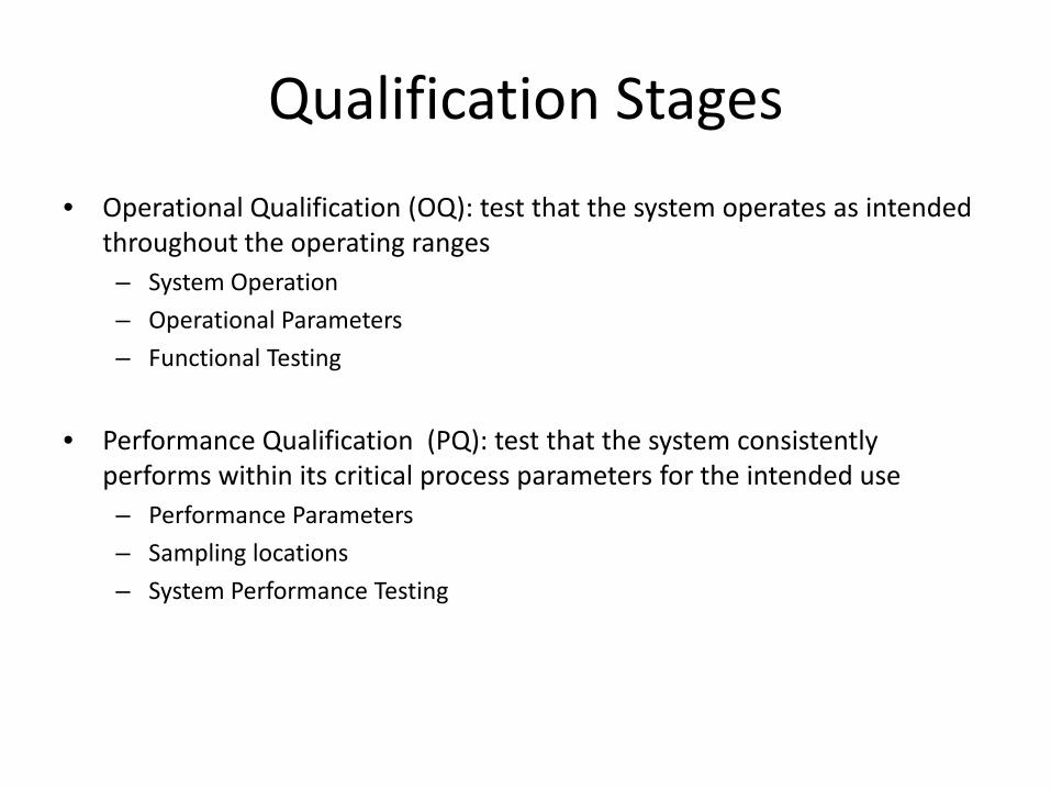
Qualification Stages • Operational Qualification (OQ): test that the system operates as intended
throughout the operating ranges – System Operation – Operational Parameters – Functional Testing
• Performance Qualification (PQ): test that the system consistently
performs within its critical process parameters for the intended use – Performance Parameters – Sampling locations – System Performance Testing
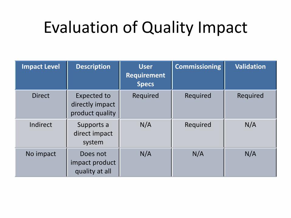
Evaluation of Quality Impact
Impact Level Description User Requirement
Specs
Commissioning Validation
Direct Expected to directly impact product quality
Required Required Required
Indirect Supports a direct impact
system
N/A Required N/A
No impact Does not impact product
quality at all
N/A N/A N/A
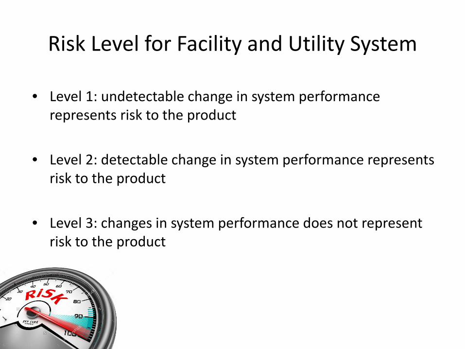
Risk Level for Facility and Utility System
• Level 1: undetectable change in system performance represents risk to the product
• Level 2: detectable change in system performance represents
risk to the product • Level 3: changes in system performance does not represent
risk to the product
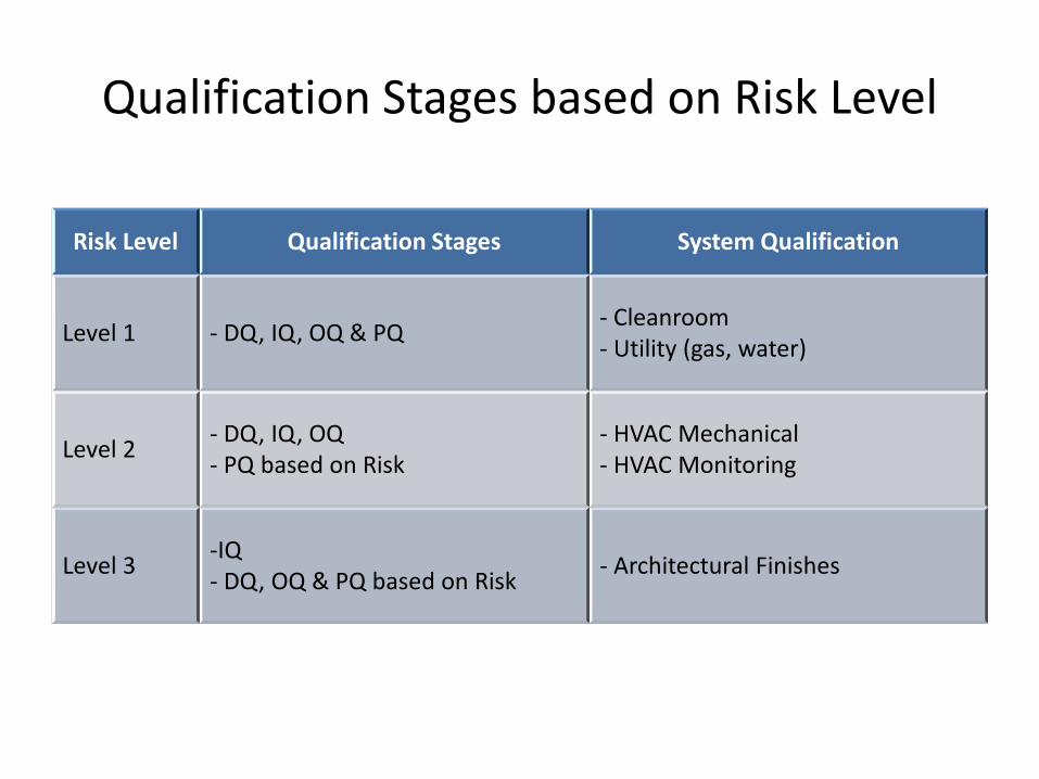
Qualification Stages based on Risk Level
Risk Level Qualification Stages System Qualification
Level 1 - DQ, IQ, OQ & PQ - Cleanroom - Utility (gas, water)
Level 2 - DQ, IQ, OQ - PQ based on Risk
- HVAC Mechanical - HVAC Monitoring
Level 3 -IQ - DQ, OQ & PQ based on Risk - Architectural Finishes
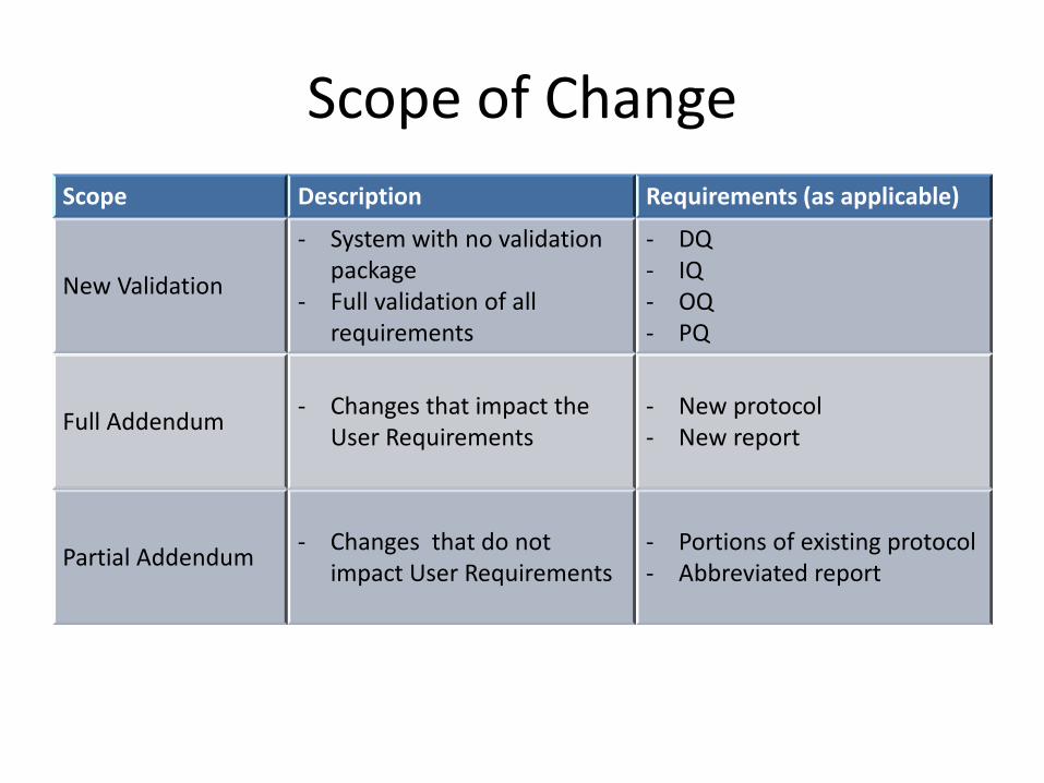
Scope of Change Scope Description Requirements (as applicable)
New Validation
- System with no validation package
- Full validation of all requirements
- DQ - IQ - OQ - PQ
Full Addendum - Changes that impact the User Requirements
- New protocol - New report
Partial Addendum - Changes that do not impact User Requirements
- Portions of existing protocol - Abbreviated report
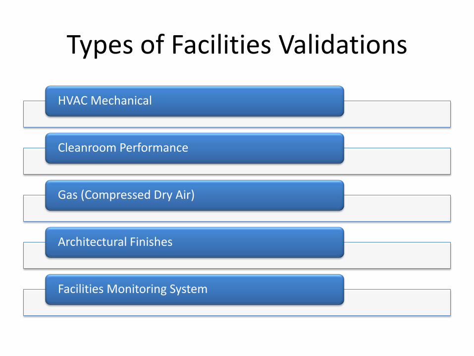
Types of Facilities Validations
HVAC Mechanical
Cleanroom Performance
Gas (Compressed Dry Air)
Architectural Finishes
Facilities Monitoring System
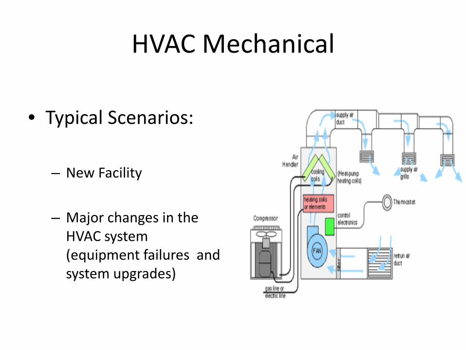
HVAC Mechanical
• Typical Scenarios: – New Facility
– Major changes in the
HVAC system (equipment failures and system upgrades)
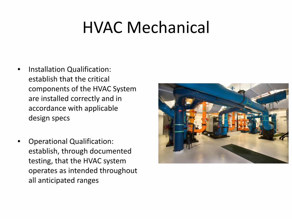
HVAC Mechanical
• Installation Qualification: establish that the critical components of the HVAC System are installed correctly and in accordance with applicable design specs
• Operational Qualification: establish, through documented testing, that the HVAC system operates as intended throughout all anticipated ranges

HVAC Mechanical
System Documentation
Drawing & Utility
Air Handling Unit
Ductwork and HEPA Filters IQ V
erifi
catio
ns
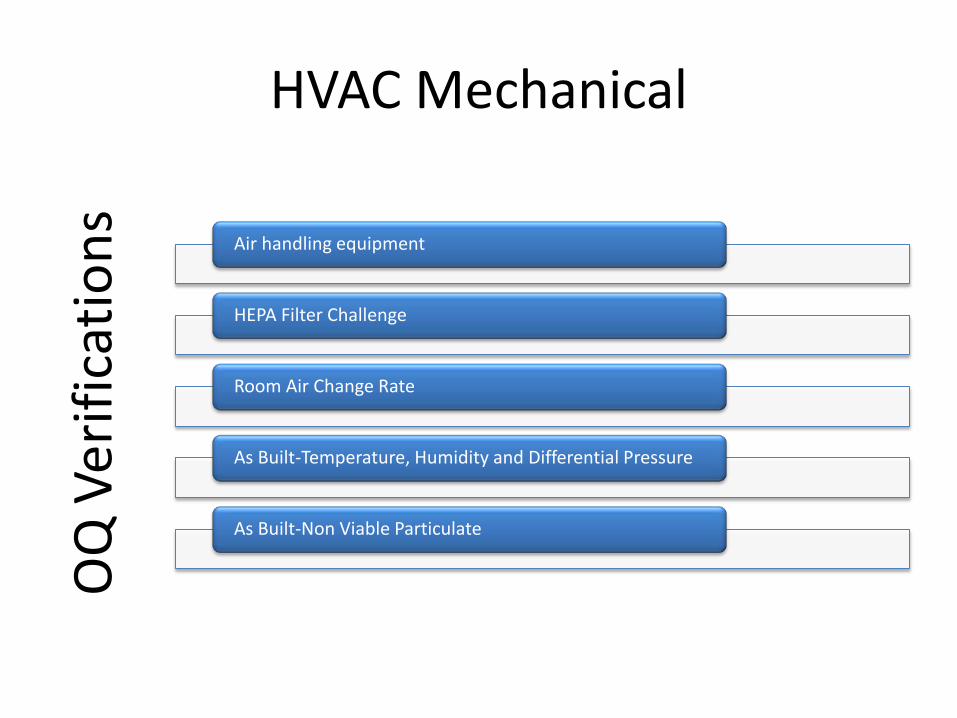
HVAC Mechanical
Air handling equipment
HEPA Filter Challenge
Room Air Change Rate
As Built-Temperature, Humidity and Differential Pressure
As Built-Non Viable Particulate
OQ
Ver
ifica
tions
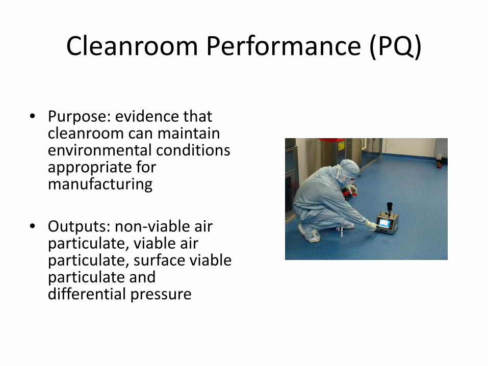
Cleanroom Performance (PQ)
• Purpose: evidence that cleanroom can maintain environmental conditions appropriate for manufacturing
• Outputs: non-viable air particulate, viable air particulate, surface viable particulate and differential pressure

Cleanroom Performance
• Strategy: testing under “At Rest” conditions and under
“Dynamic” conditions
• Testing: representative timeframe to measure outputs
• Typical Scenarios: – New facility – Major changes in the HVAC Mechanical System – Occupancy Re-validation
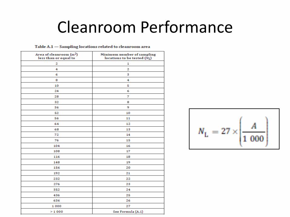
Cleanroom Performance
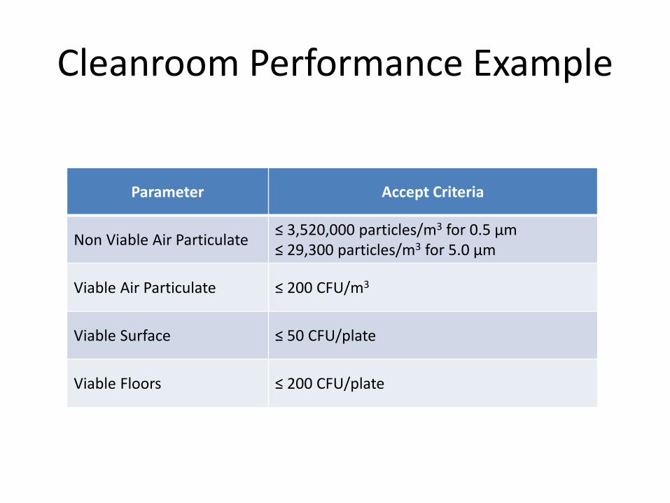
Cleanroom Performance Example
Parameter Accept Criteria
Non Viable Air Particulate ≤ 3,520,000 particles/m3 for 0.5 μm ≤ 29,300 particles/m3 for 5.0 μm
Viable Air Particulate ≤ 200 CFU/m3
Viable Surface ≤ 50 CFU/plate
Viable Floors ≤ 200 CFU/plate
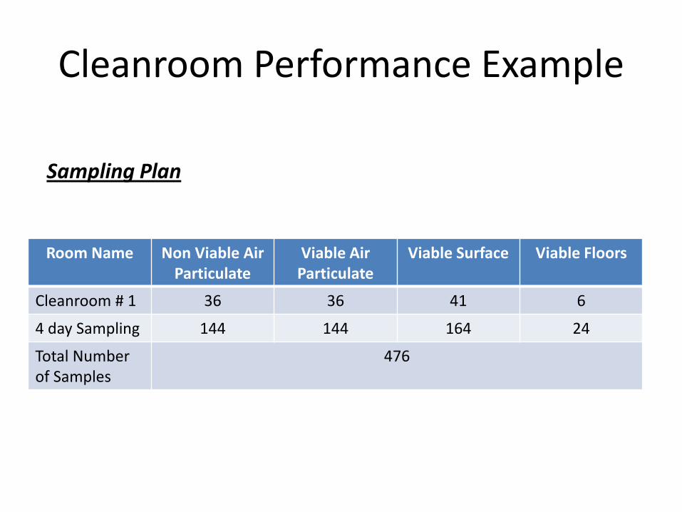
Cleanroom Performance Example
Room Name Non Viable Air Particulate
Viable Air Particulate
Viable Surface Viable Floors
Cleanroom # 1 36 36 41 6
4 day Sampling 144 144 164 24
Total Number of Samples
476
Sampling Plan
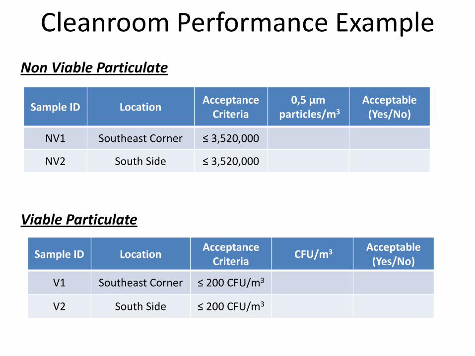
Cleanroom Performance Example Non Viable Particulate
Viable Particulate
Sample ID Location Acceptance Criteria
0,5 μm particles/m3
Acceptable (Yes/No)
NV1 Southeast Corner ≤ 3,520,000
NV2 South Side ≤ 3,520,000
Sample ID Location Acceptance Criteria CFU/m3 Acceptable
(Yes/No)
V1 Southeast Corner ≤ 200 CFU/m3
V2 South Side ≤ 200 CFU/m3
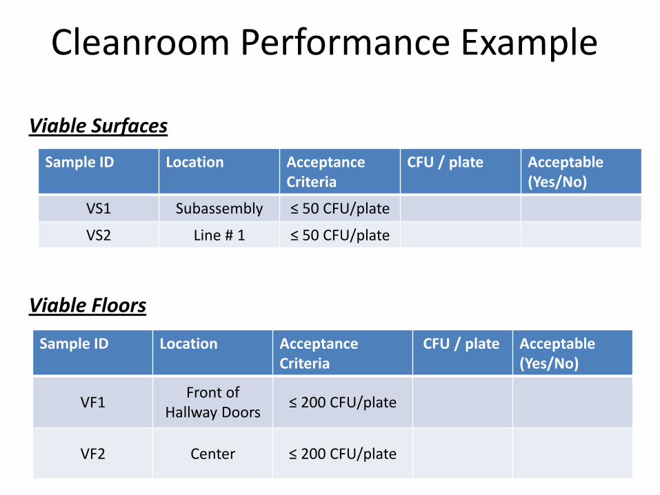
Cleanroom Performance Example Viable Surfaces
Viable Floors
Sample ID Location Acceptance Criteria
CFU / plate Acceptable (Yes/No)
VS1 Subassembly ≤ 50 CFU/plate
VS2 Line # 1 ≤ 50 CFU/plate
Sample ID Location Acceptance Criteria
CFU / plate Acceptable (Yes/No)
VF1 Front of Hallway Doors ≤ 200 CFU/plate
VF2 Center ≤ 200 CFU/plate
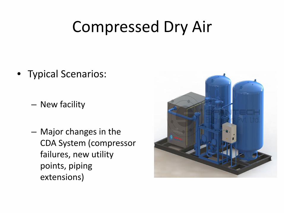
Compressed Dry Air
• Typical Scenarios:
– New facility
– Major changes in the
CDA System (compressor failures, new utility points, piping extensions)
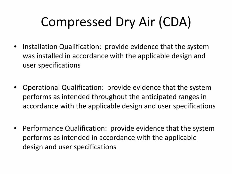
Compressed Dry Air (CDA)
• Installation Qualification: provide evidence that the system was installed in accordance with the applicable design and user specifications
• Operational Qualification: provide evidence that the system
performs as intended throughout the anticipated ranges in accordance with the applicable design and user specifications
• Performance Qualification: provide evidence that the system
performs as intended in accordance with the applicable design and user specifications

IQ V
erifi
catio
ns
Drawings
Piping Installation
Valve Identification
Compressed Dry Air
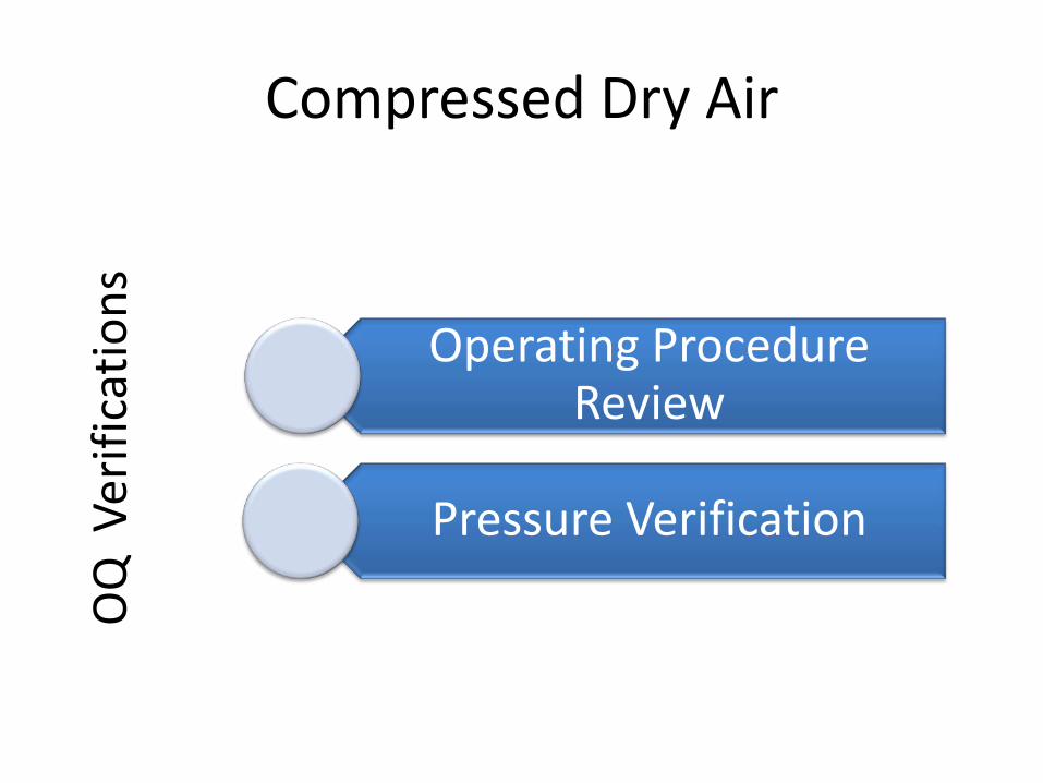
Compressed Dry Air
Operating Procedure Review
Pressure Verification
OQ
Ver
ifica
tions
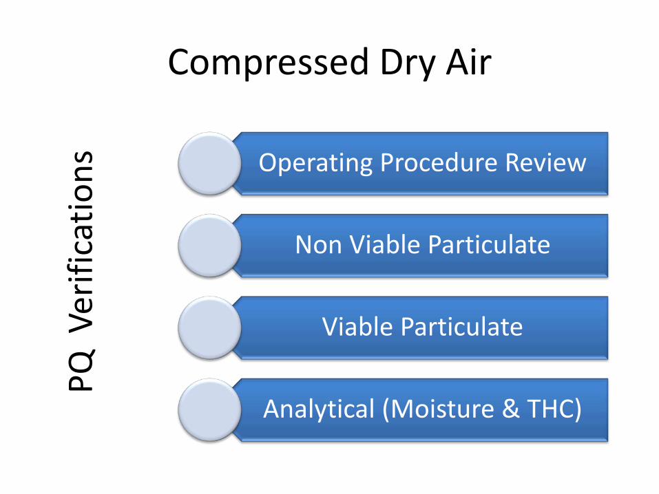
Compressed Dry Air
Operating Procedure Review
Non Viable Particulate
Viable Particulate
Analytical (Moisture & THC)
PQ V
erifi
catio
ns

Compressed Dry Air Example
Sampling Point
- Non-viable Particulate
0.5 μm: ≤ 3,520,000 μm/m3
5.0 μm: ≤ 29,300 μm/m3
- Viable Particulate
≤ 100 CFU/m3
- Moisture ≤ 128 ppm
- THC ≤ 1.0 mg/m3
LPCDA # 1
LPCDA # 2
LPCDA # 3

Architectural Finishes
• Installation Qualification Purpose: evidence that
architectural finishes were built as intended and are meeting the designs and specifications
• Outputs: Room dimensions, finish details (ceilings, walls, floors), light details, door details, door interlocks
• Accept criteria: outputs must satisfy the User Requirements Specifications
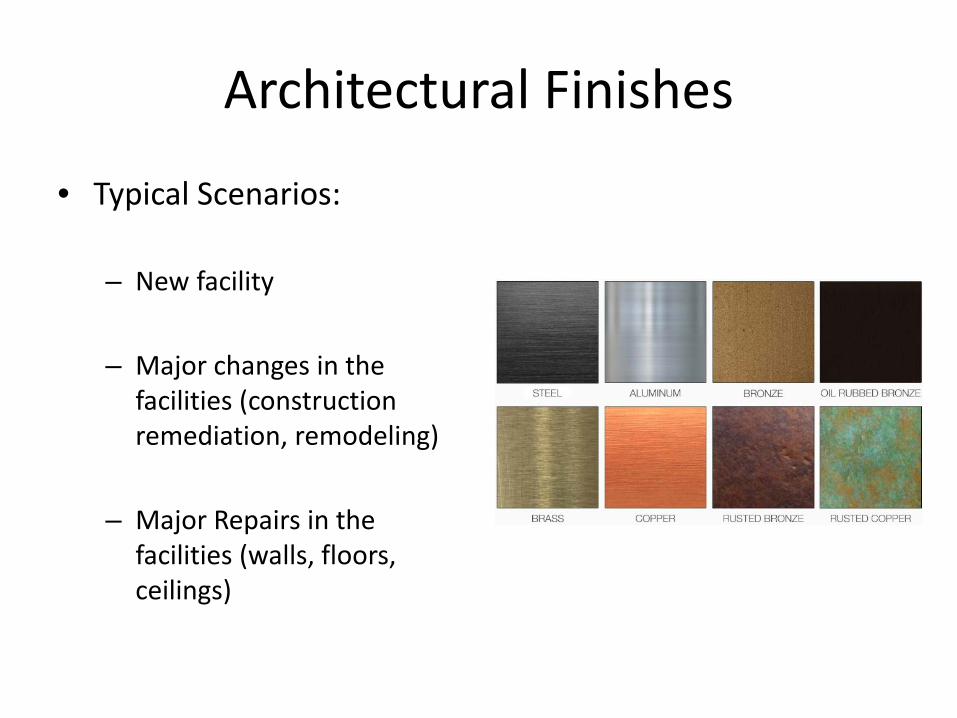
Architectural Finishes
• Typical Scenarios:
– New facility – Major changes in the
facilities (construction remediation, remodeling)
– Major Repairs in the facilities (walls, floors, ceilings)

Architectural Finishes Example
Room Dimensions and Room Volumes Room Name Room Number Room Area
(square feet) Room Volume
(cubic feet)
Cleanroom # 1 11300
Gowning # 1 11301
Cleanroom # 1 – Air Returns Description Specified Actual Acceptable
(Yes/No)
Number of Air Returns 68/Record as Found

Architectural Finishes Example
Cleanroom # 1 – Walls, Ceilings and Floors Description Specified Actual Acceptable
(Yes/No)
Wall Finish Epoxy Painted Gypsum
Floor Finish Smooth and without any gaps
Ceiling Finish Sealed with Caulking
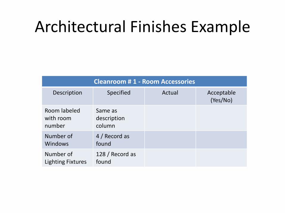
Architectural Finishes Example
Cleanroom # 1 - Room Accessories Description Specified Actual Acceptable
(Yes/No)
Room labeled with room number
Same as description column
Number of Windows
4 / Record as found
Number of Lighting Fixtures
128 / Record as found

Architectural Finishes Example
Cleanroom # 1 – Door # 87
Description Specified Actual Acceptable (Yes/No)
Door between Cleanroom and Corridor
Door opens from Corridor
Door type Single
Door and Frame Material / Finish
Hollow Metal / Epoxy Painted

Facilities Monitoring System (FMS)
• Typical Scenarios:
– New facility
– Major changes in the
system (sensor substitutions, software upgrades)

Facilities Monitoring System (FMS)
• Installation Qualification Purpose: provide evidence
that the hardware and software of the system were installed correctly
• Operational Qualification Purpose: provide evidence
that the hardware and software operates as intended throughout the anticipated ranges

Facilities Monitoring System
System Documentation
Drawing & Utility
Server and Workstation Hardware and Software
Trend and Alarm Configuration
Remote Notification Configuration
IQ V
erifi
catio
ns
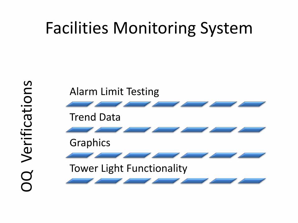
Facilities Monitoring System
Alarm Limit Testing
Trend Data
Graphics
Tower Light Functionality
OQ
Ver
ifica
tions

Protocol Documentation Requirements
Purpose and Scope
System Description
Pre-Qualification Documentation
Materials and Equipment
IQ, OQ, PQ (as applicable)
Deviations

Report Documentation Requirements
Executive Summary
Purpose and Scope
Discussion of Results
Deviation Summary
Conclusion
Executed Protocol and Supporting Docs

Dealing with Deviations…
Description of the event
Root Cause Investigation
Resolution Plan
Impact to the Study
Evidence of Completion

Maintaining the Validated State
Deep understanding of the change
Define impact throughout change management system
Outline deliverables to be completed

Interactive Exercise
Let’s discuss about your experiences and lessons learned!!
Contact Information
• Mauricio Chinchilla Romero • Senior Validation Engineer • Abbott Vascular • [email protected] • (506) 2484 20 79
Recommended