A Unique Pendulum Impact Apparatus Capstone Design Project for a Hands-
On Senior-Level Laboratory Design Experience Yin-ping (Daniel) Chang, Oakland University
Abstract
This paper describes a particle kinetics work/energy and impulse/momentum measurement experiment for
the senior level Engineering Mechanics – Dynamics course. This course introduces students to the
fundamental principles of kinematics and kinetics of particles and rigid bodies, including
displacement/velocity/acceleration kinematic relationships and kinetic analyses through Newtonian laws
of motion, work/energy conservation laws, and impulse/momentum approaches. It has been the
Mechanical Engineering Department’s philosophy that theory learned in the classroom be augmented by
experiential knowledge gained by laboratory experience. In this light, hands-on laboratory experiments
have been developed that are integrated with the course material. This paper presents a unique
experimental apparatus, designed and built at Oakland University, by senior-level students involved in a
design project. The purpose is to introduce students to particle kinetics properties measurement
techniques to measure particles’ velocities, energy transfer and dissipation, and the coefficient of
restitution during impact phenomena in a pendulum impact system. The experiment covers basic concepts
of kinetics of particles, specially focusing on impulse/momentum related principles. Two objects were
used in this impact apparatus. One object was set up as a pendulum, being raised up and swung down to
impact a stationary object. The first object was raised up to store the gravitational potential energy, and
then swung down to transform the gravity potential energy into kinetic energy; this object then impacted
the other object, transferred part of the momentum to the other object, the other object gained the
momentum and transferred it into kinetic energy. The energy was then dissipated by friction when the
object traveled on a flat surface. The students were asked to validate the particle kinetics law of
conservation of energy and impulse/momentum principles. Results of the students’ experiences will be
presented in this paper.
Key Words
Engineering Curricula
A Unique Pendulum Impact Apparatus Capstone Design Project
for a Hands-On Senior-Level Laboratory Design Experience
Y. P. Chang, Ph.D.
Department of Mechanical Engineering
Oakland University
Rochester, MI 48309-4478
1. ABSTRACT
This paper describes a particle kinetics work/energy and impulse/momentum measurement
experiment for the senior level Engineering Mechanics – Dynamics course. This course
introduces students to the fundamental principles of kinematics and kinetics of particles and rigid
bodies, including displacement/velocity/acceleration kinematic relationships and kinetic analyses
through Newtonian laws of motion, work/energy conservation laws, and impulse/momentum
approaches. It has been the Mechanical Engineering Department’s philosophy that theory learned
in the classroom be augmented by experiential knowledge gained by laboratory experience. In
this light, hands-on laboratory experiments have been developed that are integrated with the
course material. This paper presents a unique experimental apparatus, designed and built at
Oakland University, by senior-level students involved in a design project. The purpose is to
introduce students to particle kinetics properties measurement techniques to measure particles’
velocities, energy transfer and dissipation, and the coefficient of restitution during impact
phenomena in a pendulum impact system. The experiment covers basic concepts of kinetics of
particles, specially focusing on impulse/momentum related principles. Two objects were used in
this impact apparatus. One object was set up as a pendulum, being raised up and swung down to
impact a stationary object. The first object was raised up to store the gravitational potential
energy, and then swung down to transform the gravity potential energy into kinetic energy; this
object then impacted the other object, transferred part of the momentum to the other object, the
other object gained the momentum and transferred it into kinetic energy. The energy was then
dissipated by friction when the object traveled on a flat surface. The students were asked to
validate the particle kinetics law of conservation of energy and impulse/momentum principles.
Results of the students’ experiences will be presented in this paper.
2. OBJECTIVES
With all engineering classes, labs play an important role in relating the theory discussed in class
to practical applications. However, ME321 Dynamics and Vibration at Oakland University,
lacks this core component which helps bridge the theory and the practical aspects. As a result, a
lab experiment was designed, built, and tested that can be integrated into the curriculum directly.
The objective of this lab was to introduce particle kinetics, especially focuses on work/energy
and impulse/momentum concepts and approaches. From the apparatus designed, two blocks,
aluminum and steel were impacted by a pendulum attached with a steel cylinder. The
experiment was conducted with the pendulum set to 30o and 50
o angles. The distance traveled by
the block upon impact was measured and recorded. Initial and final velocities were calculated
for the block and cylinder, which were used to determine coefficient of restitution. This
experiment demonstrated two different approaches need be used at the same time to evaluate
problems involving collisions.
3. DESIGN OF EXPERIMENT
The basic concept behind this laboratory was to develop a user friendly lab that would help
enrich the material that is learned in class. The idea was to create a pendulum that would swing
freely and contact another object, in which the traveled distance could be measured. There were
a few specified design constraints that had to be considered. The overall structure had to be light
in weight and smaller in size to allow for easy transportation, and it could last over time and
continue to be effective tools for enhancing the lectured material.
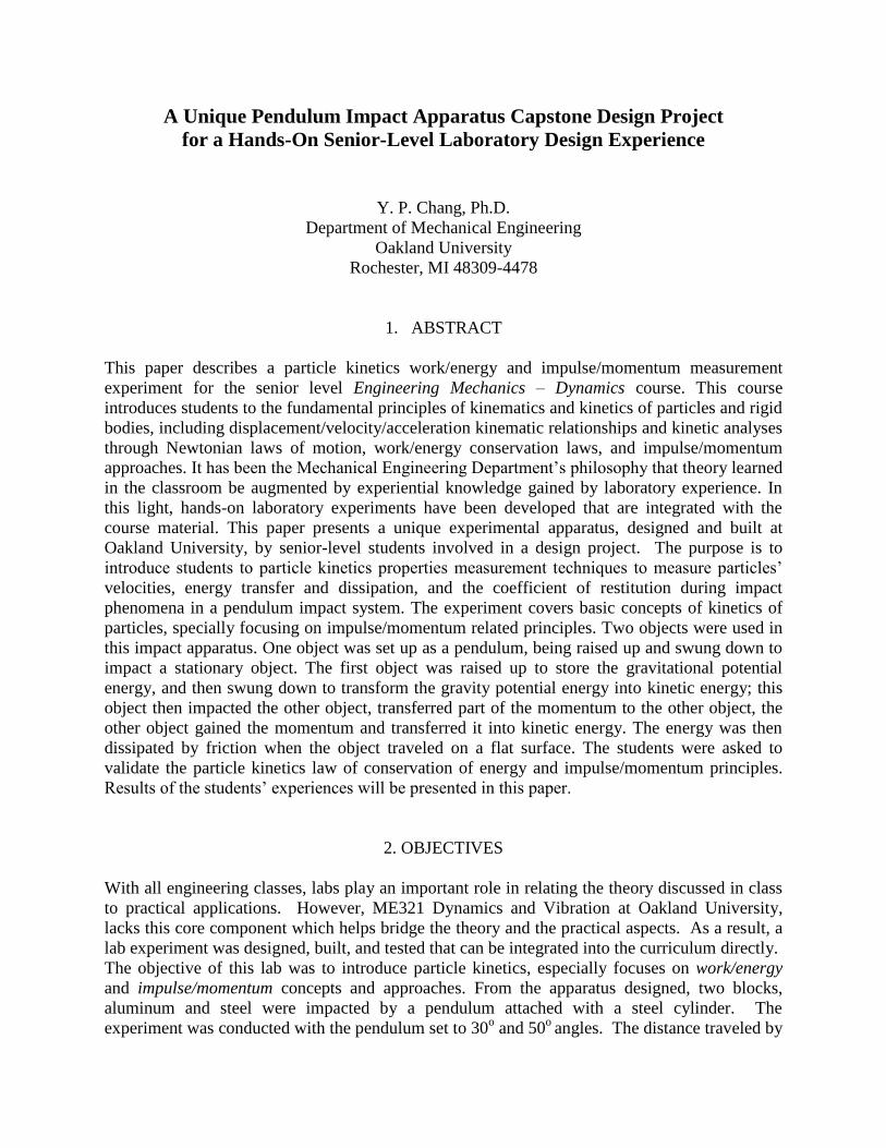
Computer aided design software was used in the process of designing the lab. AutoCAD 14 and
AutoDesk Viz 4.0 were tools used in creating the laboratory models. AutoCAD 14 was used to
accurately dimension each component and to give final schematics of the completed structures.
AutoDesk Viz 4.0 is a type of software that basically brings AutoCAD to life. It was used to
provide a complete 3-D model including accurate surface textures and colors. After the model
was created, this software ran a simulation of the experiment. This is an effective aid to give a
general idea of how the laboratory is to be run.
Figure 1 - The Lab ISO View

Figure 2 - Sample Dimensions
4. MANUFACTURE
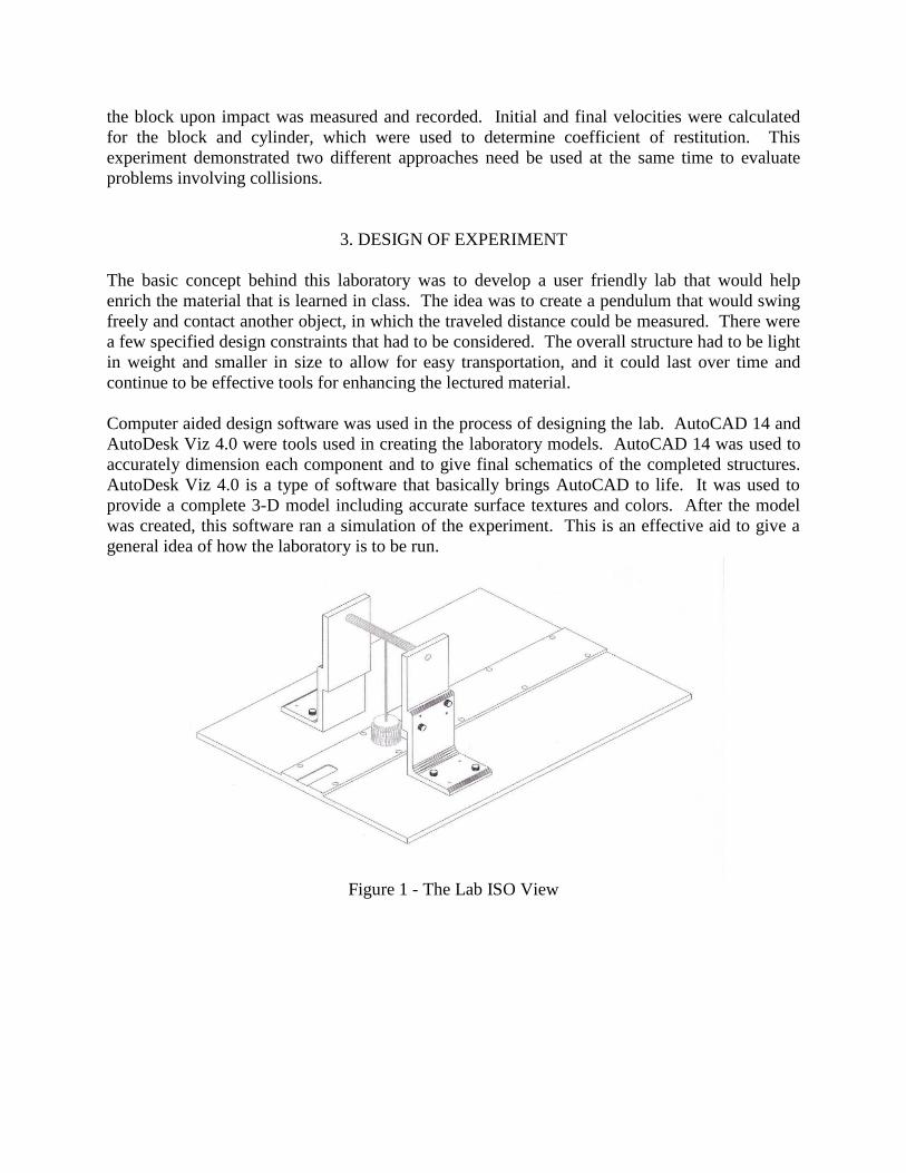
Friction tests were conducted between two identical aluminum surfaces and also between a steel
and aluminum surface. The registered ASTM D 1894 standard friction test yielded results that
were used for laboratory calculations. The sample blocks were conditioned at standard
laboratory conditions of 21± 2oC and 50 ± 5% relative humidity for a minimum 24 hours prior to
testing. The coefficient of friction test was performed on an Instron machine using TestWorks
3.1 software. A desired material block was placed on a desired surface. The block was then
pulled at a constant speed of 150 mm/min to determine the coefficient of friction between the
two materials. This was repeated two more times (total of three times) and the average value
was taken in order to determine the theoretical coefficient of friction. The coefficient of friction
is a resistive force encountered between two objects either stationary or in motion. Since this lab
analyzed the motion of objects, it was necessary to determine the dynamic coefficient of friction.
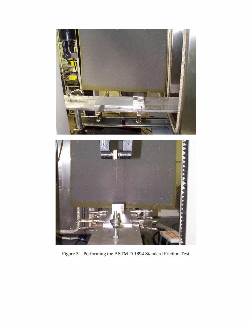
Figure 3 – Performing the ASTM D 1894 Standard Friction Test

Table 1 – A Sample of Coefficient of Friction Test Data
For all components, clearance holes were drilled and reamed (smoothing radius of the hole) for
screw and dowel placement. The first step was to machine two identical blocks, one of
aluminum and one of steel. These will be the blocks that are struck by the pendulum. Also, a
steel cylinder was fabricated to a specified dimension. This is the component that will be
striking the identical blocks of steel and aluminum. A tooling plate (alum. w/ parallel surfaces)
was used as the base. Jig feet (hardened rubber pads) were screwed to the bottom of the tooling
plate to enable the lab experiment to be transported whenever needed.
Two aluminum risers were setup, then the steel rod is mounted between the risers. The steel
cylinder was then connected to the lightweight threaded rod. A degree indicator was mounted on
the side of the aluminum riser. This will allow the pendulum to be set to a desired angle prior to
deployment.
Figure 4 – The Lab Apparatus
Upon completion of the lab, testing was done to check for possible problems. A few glaring
problems were identified. A student setting the pendulum to a certain degree and releasing the
cylinder had no way of obtaining the desired angle every time constantly. In addition, the block
sitting stationary on the apparatus was not set up in the same position twice. This offsetting of
the stationary block yielded an oblique impact between the two objects. These variables caused
enormous errors during testing. The release of the pendulum and the placement of the block
needed to be regulated. Fabricating a v-notch block that the pendulum could rest on created a
stable starting point. To release the pendulum the v-notch block was simply pulled out and the
pendulum could swing straight and free. The placement of the block was constrained by
grinding a thin piece of steel down to almost nothing. The piece of steel had a portion, the width
of the block, machined out of it; therefore the block could rest against the piece of steel perfectly.
This design iteration constrained the movement of the block. After these quality issues were
addressed, lab was tested again, and now it met the R & R (Repeatability and Reliability)
specifications.
5. ANALYSIS OF THE EXPERIMENT
The discrepancies between theoretical and experimental velocities after impact can be attributed
to the assumption that the coefficient of restitution was equivalent to 1. From analysis of the
experimental data, the coefficient of restitution was shown to be not exactly 1. This can be

attributed to the impact velocity, size, shape, and temperature causing variations. In addition,
since the coefficient of restitution was not exactly 1, there was energy loss during impact
between the cylinder and block. Another source of error can be attributed to oblique central
impact of the cylinder and block. If the cylinder and block collide where the line of impact is not
central then the collision is considered to be eccentric (oblique impact). Eccentric collisions
reduce the distribution of energy which in turn reduces the velocities. Another contributing
factor to the discrepancies in the calculated velocities was due to friction between the contact
surfaces. This variation can be contributed to the different forces inflicted on the blocks caused
by variations in speeds at which the system is initially run at. Secondly, surface defects played a
role in the discrepancies with each trail when determining the coefficient of friction. The surface
defects attributed to restricted motion on the block as it travels the length of the apparatus,
implying that speed isn’t constant. But in order to determine the coefficient of friction, it is
necessary to have a constant speed. As a result, the tabulated values needed to be calculated for
each mass tested in order to reduce the percent error from these discrepancies.
6. CONCLUSION
It was concluded that this experiment will be beneficial to reinforcing the theory for dynamics.
This lab provided a hands on approach as well as an opportunity to apply the theoretical
equations and concepts. The experiment demonstrated the reliability and repeatability needed to
accurately portray the situations discussed in class. After running the laboratory students will
have exercised their general knowledge of physics and dynamics in real life situations and draw
upon their own conclusions as modes for interpretation. Possible improvements could include
the installation of a force gage allows more direct parameters of the object to be measured during
impact; a digital angle measurement device could provide a more accurate reading.
7. ACKNOWLEDGEMENT
The author would like to acknowledge four students, Mr. Hanh Ho, Huy Dang, Michael Withee
and Robert Manoni who have participated in this particular design project in fall 2003 semester
at Oakland University. Their enthusiasm, creative thinking, and inquiring questions during their
attempts to synthesize better designs, continually fuels the enthusiasm as teachers to discover and
develop new ideas and methods to enhance our effectiveness as engineering educators.
Author’s Brief Biographical and Contact Information
Yin-ping (Daniel) Chang, Ph.D., he received his Ph.D. degree in 2002 and continues his research as an assistant
professor at Oakland University, Rochester, Michigan. His current research interests include vehicle/tire dynamics,
FEA computational solid mechanics, biomechanics, machine dynamics, machine design, and classical mechanism
synthesis and analysis. E-mail address: [email protected], website: www.oakland.edu/~ychang.
ME 321 : Dynamics and Vibrations
Laboratory Experiment #5 Assignment : Lab Handout
Particles Kinetics – Work/Energy and Impulse/Momentum Approach:
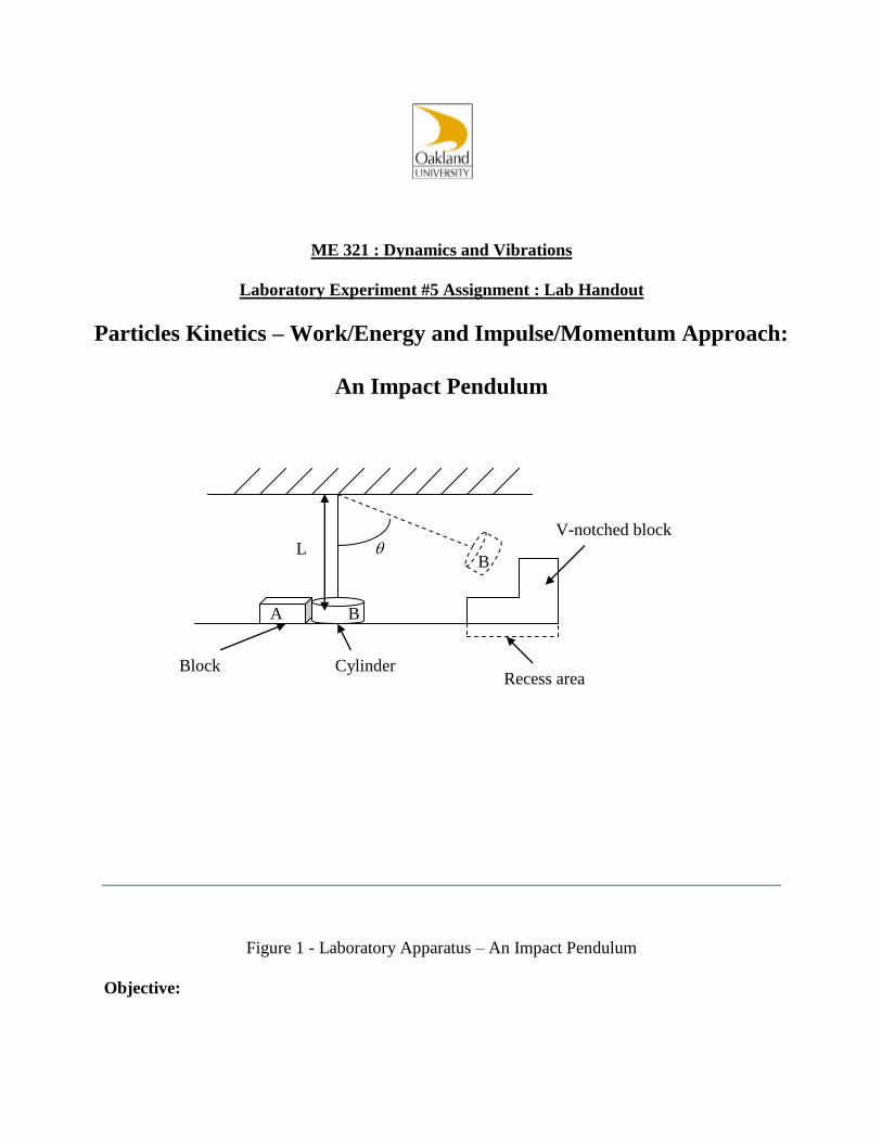
An Impact Pendulum
Figure 1 - Laboratory Apparatus – An Impact Pendulum
Objective:
L
B
B
A
Recess area
V-notched block
Block Cylinder

The purpose of this experiment is to introduce the principles of work/energy and
impulse/momentum.
Theory:
This lab experiment is based upon the Work/Energy (1) and Impulse/Momentum (2) Principles.
Ti +V
i +U
i→f = T
f +V
f (1)
M A V
i + ∫ F dt = M
A V
f (for individual particle) (2a)
M A V
Ai + M
B V
Bi = M
A V
Af + M
B V
Bf (for multi objects) (2b)
Procedure:
1. Measure the masses of both block A’s, and rod length L.
(Note: The rod length is from the center of the shaft to the center of the cylinder B. Why?)
2. With the experimental apparatus provided, set up the experiment as shown in the sketch.
3. Place the block (aluminum or steel) provided at the scribed starting position.
4. Place the V-notched block in recess area.
5. Rest the pendulum on V-notched block.
6. Remove the V-notched block to deploy the pendulum.
(Note: Remove V-notched block quickly and smoothly, practice several times before you take
the measurements. Make sure to remove the V-notched Block consistently.)
7. Measure the distance traveled by the block and the angle of the pendulum before and after
the impact.
(Note: The distance traveled by the block should be measured from the center of the blocks
no matter the blocks rotate or not.)
8. Run this experiment 10 times and take the average measurements.
9. Repeat the experiment with another angle of the pendulum and then another block.
Report & Discussion: (For all 4 cases.)
1. Find the velocity of the cylinder B before and after impact.
2. Find the velocity of the block A right after the impact.

3. Determine coefficient of restitution.
4. Determine coefficient of friction between the block and the apparatus surface.
5. Discussions.

ME 321 : Dynamics and Vibrations
Laboratory Experiment #5 Assignment: Example Lab Report
Particles Kinetics – Work/Energy and Impulse/Momentum Approach:
An Impact Pendulum
Submitted to: Prof. Yin-ping Chang
Prepared by:
Hanh Ho
Huy Dang
Michael Withee
Robert Manoni
Introduction
The objective of this experiment was to introduce the concepts of work/energy and
impulse/momentum methods. From the apparatus provided, two blocks, aluminum and steel,
were impacted by a pendulum attached with a steel cylinder. The experiment was conducted
with the pendulum set to 30o and 50
o angles. The distance traveled by the block upon impact was
measured and recorded. Initial and final velocities were calculated for the block and cylinder,
which were used to determine coefficient of restitution.
Theory
This experiment entailed Work/Energy Principle and Impulse/Momentum Approach. Work is
defined as:
rdFW (1)
Basically, there are three forms of work/energy: potential energy (V), kinetic energy (T), and a
general energy format (U1
2), where the work is done on an object from some initial position, 1,
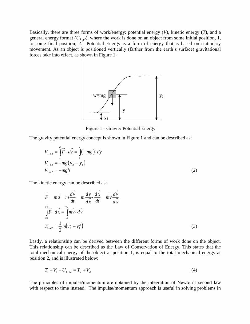
to some final position, 2. Potential Energy is a form of energy that is based on stationary
movement. As an object is positioned vertically (farther from the earth’s surface) gravitational
forces take into effect, as shown in Figure 1.
The gravity potential energy concept is shown in Figure 1 and can be described as:
2
1
2
1
21 dymgrdFV
1221 yymgV
mghV 21 (2)
The kinetic energy can be described as:
xd
vdvm
dt
xd
xd
vdm
dt
vdmamF
vdvmxdF
v
v
x
x
2
1
2
1
2
1
2
2212
1vvmT (3)
Lastly, a relationship can be derived between the different forms of work done on the object.
This relationship can be described as the Law of Conservation of Energy. This states that the
total mechanical energy of the object at position 1, is equal to the total mechanical energy at
position 2, and is illustrated below:
222111 VTUVT (4)
The principles of impulse/momentum are obtained by the integration of Newton’s second law
with respect to time instead. The impulse/momentum approach is useful in solving problems in
y
y2 w=mg
y1
Figure 1 - Gravity Potential Energy

which the velocities of a body at two different instants are to be related and the forces involved
can be expressed as functions of time.
vmdt
damF
vdmFdt
2
2
1
1 vmFdtvm (5)
21 vmvm when
2
1
0Fdt
Where the force, F is an internal reaction force between the objects during impact time, dt.
The collision of two objects can be divided into two separate phases, deformation and
restoration. The deformation phase exists from the moment of contact until the two objects
attain a common velocity. The restoration phase exists from the end of the deformation phases
until the objects are separated. The ratio of these two impulses is defined as the coefficient of
restitution, e.
mvtFmv mvmv
bbaabbaa vmvmvmvm ''
For object b:
URvb ' bvPU
UmRdtvm bbb '
bbb vmPdtUm
Umvm
vmUm
Pdt
Rdte
bbb
bbb
'
Similar, for object a:
a b a a b b
ba vv U ba vv
aaa
aaa
vmUm
Umvm
Pdt
Rdte
'
Therefore the coefficient of restitution, ab
ba
ab
ab
vv
vv
vUUv
UvvU
Pdt
Rdte
''''
(6)
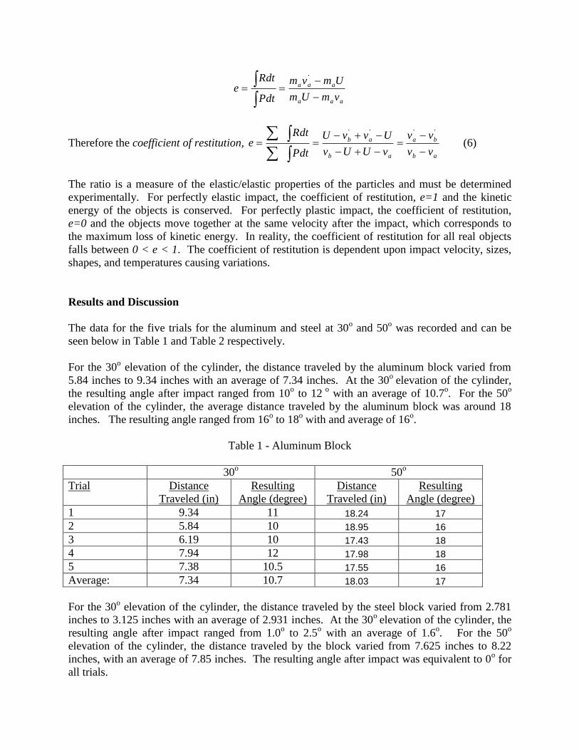
The ratio is a measure of the elastic/elastic properties of the particles and must be determined
experimentally. For perfectly elastic impact, the coefficient of restitution, e=1 and the kinetic
energy of the objects is conserved. For perfectly plastic impact, the coefficient of restitution,
e=0 and the objects move together at the same velocity after the impact, which corresponds to
the maximum loss of kinetic energy. In reality, the coefficient of restitution for all real objects
falls between 0 < e < 1. The coefficient of restitution is dependent upon impact velocity, sizes,
shapes, and temperatures causing variations.
Results and Discussion
The data for the five trials for the aluminum and steel at 30o and 50
o was recorded and can be
seen below in Table 1 and Table 2 respectively.
For the 30o elevation of the cylinder, the distance traveled by the aluminum block varied from
5.84 inches to 9.34 inches with an average of 7.34 inches. At the 30o
elevation of the cylinder,
the resulting angle after impact ranged from 10o to 12
o with an average of 10.7
o. For the 50
o
elevation of the cylinder, the average distance traveled by the aluminum block was around 18
inches. The resulting angle ranged from 16o to 18
o with and average of 16
o.
Table 1 - Aluminum Block
30o 50
o
Trial Distance
Traveled (in)
Resulting
Angle (degree)
Distance
Traveled (in)
Resulting
Angle (degree)
1 9.34 11 18.24 17
2 5.84 10 18.95 16
3 6.19 10 17.43 18
4 7.94 12 17.98 18
5 7.38 10.5 17.55 16
Average: 7.34 10.7 18.03 17
For the 30o elevation of the cylinder, the distance traveled by the steel block varied from 2.781
inches to 3.125 inches with an average of 2.931 inches. At the 30o
elevation of the cylinder, the
resulting angle after impact ranged from 1.0o to 2.5
o with an average of 1.6
o. For the 50
o
elevation of the cylinder, the distance traveled by the block varied from 7.625 inches to 8.22
inches, with an average of 7.85 inches. The resulting angle after impact was equivalent to 0o for
all trials.
Table 2 - Steel Block
30o 50
o
Trial Distance
Traveled (in)
Resulting
Angle (degree)
Distance
Traveled (in)
Resulting
Angle (degree)
1 3.125 2.5 7.81 0
2 2.813 1.0 7.69 0
3 2.781 2.0 7.625 0
4 2.938 1.5 7.94 0
5 3.000 1.0 8.22 0
Average: 2.931 1.6 7.85 0
From the data recorded the velocity before and after impact for the cylinder was calculated for
each trial. The velocity before impact for the cylinder was calculated using the work/energy
method. The velocities were 2.47 ft/sec for the 30o angle and 4.04 ft/sec for the 50
o angle. In
contrast the impulse/momentum approach was used to determine the final velocity after impact
for the cylinder. For the aluminum and steel impact at a 30o elevation, the velocity of the
cylinder ranged from 0.77 ft/sec to 1.124 ft/sec, with an average of 0.967 ft/sec. For the 50o
elevation, the final velocity of the cylinder was 1.672 ft/sec. For the steel on steel impact, the
final velocity of the cylinder for the 30o elevation ranged from -0.265 ft/sec to -0.111 ft/sec with
an average of -0.179 ft/sec. For the 50o elevation, the final velocity of the cylinder ranged from -
0.402 ft/sec to -0.239 ft/sec with an average of -0.301 ft/sec. Negative velocities is in reference to
the direction traveled.
The impulse/momentum approach was used to calculate the initial velocity of the aluminum
block right after impact as well. For the 30o elevation, the velocity after impact for the
aluminum block ranged from 3.280 ft/sec to 4.147 ft/sec, with an average of 3.675 ft/sec. For the
50o elevation, the velocity of the block after impact was 5.76 ft/sec. Similarly, the velocity for
the steel block after impact was also calculated. For the 30o
elevation, the initial velocity of the
block ranged from 2.168 ft/sec to 2.298 ft/sec, with an average of 2.226 ft/sec. For the 50o
elevation, the velocity of the block after impact ranged from 3.590 ft/sec to 3.727 ft/sec, with and
average of 3.643 ft/sec.
For comparison, the theoretical velocities for the cylinder and block after impact were
determined using impulse/momentum with coefficient of restitution e=1. The average theoretical
velocity for the cylinder after impacting the aluminum block was 1.302 ft/sec and 1.686 ft/sec for
the 30o and 50
o deflection respectively. For the cylinder impacting the steel block, the average
theoretical velocity for the cylinder after impact was -0.210 ft/sec and -0.350 ft/sec. The
average theoretical velocity for the aluminum block after impact was 3.502 ft/sec and 5.720
ft/sec for the 30o and 50
o deflection respectively. The average theoretical velocity for the steel
block after impact was 2.250 ft/sec and 3.680 ft/sec. Percentage error between theoretical and
experimental velocities for the cylinder and block after impact was also analyzed. The percent
error for velocity of the cylinder after impacting the aluminum block was 6.262% and 0.811%
for the 30o and 50
o deflection of the pendulum respectively. For the cylinder impacting the steel
block, the percent error was 14.91% and 14.0% for the 30o and 50
o deflection respectively.
The
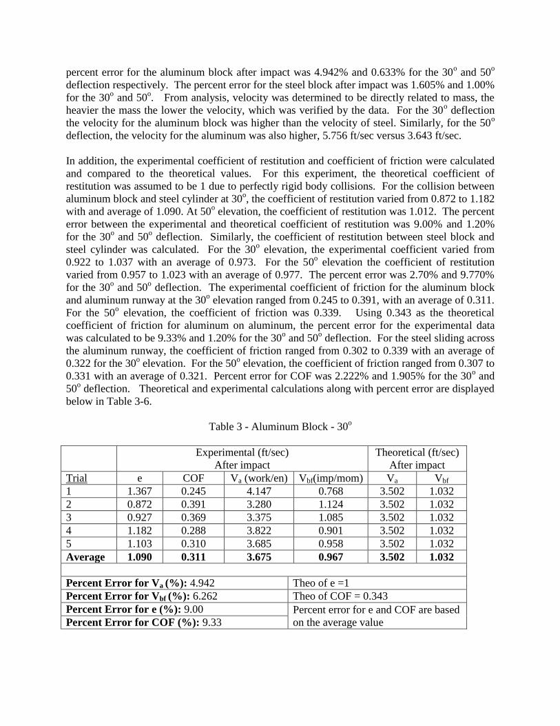
percent error for the aluminum block after impact was 4.942% and 0.633% for the 30o and 50
o
deflection respectively. The percent error for the steel block after impact was 1.605% and 1.00%
for the 30o and 50
o. From analysis, velocity was determined to be directly related to mass, the
heavier the mass the lower the velocity, which was verified by the data. For the 30o deflection
the velocity for the aluminum block was higher than the velocity of steel. Similarly, for the 50o
deflection, the velocity for the aluminum was also higher, 5.756 ft/sec versus 3.643 ft/sec.
In addition, the experimental coefficient of restitution and coefficient of friction were calculated
and compared to the theoretical values. For this experiment, the theoretical coefficient of
restitution was assumed to be 1 due to perfectly rigid body collisions. For the collision between
aluminum block and steel cylinder at 30o, the coefficient of restitution varied from 0.872 to 1.182
with and average of 1.090. At 50o elevation, the coefficient of restitution was 1.012. The percent
error between the experimental and theoretical coefficient of restitution was 9.00% and 1.20%
for the 30o and 50
o deflection. Similarly, the coefficient of restitution between steel block and
steel cylinder was calculated. For the 30o elevation, the experimental coefficient varied from
0.922 to 1.037 with an average of 0.973. For the 50o elevation the coefficient of restitution
varied from 0.957 to 1.023 with an average of 0.977. The percent error was 2.70% and 9.770%
for the 30o and 50
o deflection. The experimental coefficient of friction for the aluminum block
and aluminum runway at the 30o elevation ranged from 0.245 to 0.391, with an average of 0.311.
For the 50o elevation, the coefficient of friction was 0.339. Using 0.343 as the theoretical
coefficient of friction for aluminum on aluminum, the percent error for the experimental data
was calculated to be 9.33% and 1.20% for the 30o and 50
o deflection. For the steel sliding across
the aluminum runway, the coefficient of friction ranged from 0.302 to 0.339 with an average of
0.322 for the 30o elevation. For the 50
o elevation, the coefficient of friction ranged from 0.307 to
0.331 with an average of 0.321. Percent error for COF was 2.222% and 1.905% for the 30o and
50o deflection. Theoretical and experimental calculations along with percent error are displayed
below in Table 3-6.
Table 3 - Aluminum Block - 30o
Experimental (ft/sec)
After impact
Theoretical (ft/sec)
After impact
Trial e COF Va (work/en) Vbf(imp/mom) Va Vbf
1 1.367 0.245 4.147 0.768 3.502 1.032
2 0.872 0.391 3.280 1.124 3.502 1.032
3 0.927 0.369 3.375 1.085 3.502 1.032
4 1.182 0.288 3.822 0.901 3.502 1.032
5 1.103 0.310 3.685 0.958 3.502 1.032
Average 1.090 0.311 3.675 0.967 3.502 1.032
Percent Error for Va (%): 4.942 Theo of e =1
Percent Error for Vbf (%): 6.262 Theo of COF = 0.343
Percent Error for e (%): 9.00 Percent error for e and COF are based
on the average value Percent Error for COF (%): 9.33
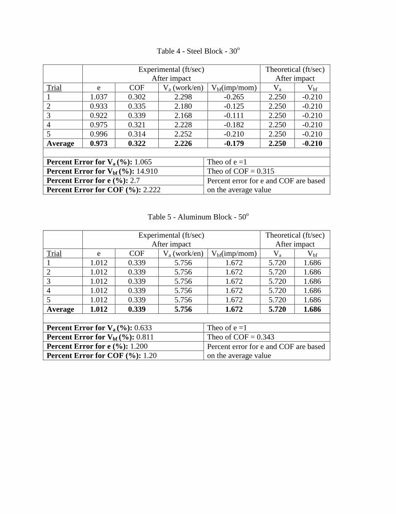
Table 4 - Steel Block - 30o
Experimental (ft/sec)
After impact
Theoretical (ft/sec)
After impact
Trial e COF Va (work/en) Vbf(imp/mom) Va Vbf
1 1.037 0.302 2.298 -0.265 2.250 -0.210
2 0.933 0.335 2.180 -0.125 2.250 -0.210
3 0.922 0.339 2.168 -0.111 2.250 -0.210
4 0.975 0.321 2.228 -0.182 2.250 -0.210
5 0.996 0.314 2.252 -0.210 2.250 -0.210
Average 0.973 0.322 2.226 -0.179 2.250 -0.210
Percent Error for Va (%): 1.065 Theo of e =1
Percent Error for Vbf (%): 14.910 Theo of COF = 0.315
Percent Error for e (%): 2.7 Percent error for e and COF are based
on the average value Percent Error for COF (%): 2.222
Table 5 - Aluminum Block - 50o
Experimental (ft/sec)
After impact
Theoretical (ft/sec)
After impact
Trial e COF Va (work/en) Vbf(imp/mom) Va Vbf
1 1.012 0.339 5.756 1.672 5.720 1.686
2 1.012 0.339 5.756 1.672 5.720 1.686
3 1.012 0.339 5.756 1.672 5.720 1.686
4 1.012 0.339 5.756 1.672 5.720 1.686
5 1.012 0.339 5.756 1.672 5.720 1.686
Average 1.012 0.339 5.756 1.672 5.720 1.686
Percent Error for Va (%): 0.633 Theo of e =1
Percent Error for Vbf (%): 0.811 Theo of COF = 0.343
Percent Error for e (%): 1.200 Percent error for e and COF are based
on the average value Percent Error for COF (%): 1.20
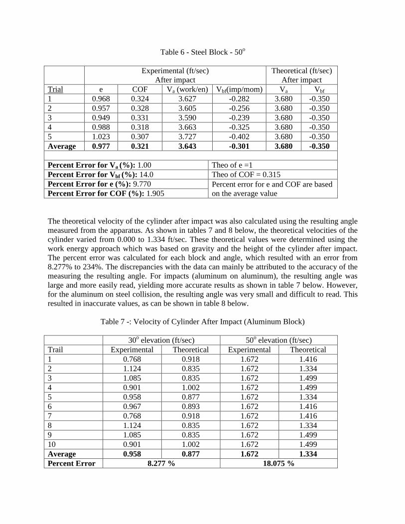
Table 6 - Steel Block - 50o
Experimental (ft/sec)
After impact
Theoretical (ft/sec)
After impact
Trial e COF Va (work/en) Vbf(imp/mom) Va Vbf
1 0.968 0.324 3.627 -0.282 3.680 -0.350
2 0.957 0.328 3.605 -0.256 3.680 -0.350
3 0.949 0.331 3.590 -0.239 3.680 -0.350
4 0.988 0.318 3.663 -0.325 3.680 -0.350
5 1.023 0.307 3.727 -0.402 3.680 -0.350
Average 0.977 0.321 3.643 -0.301 3.680 -0.350
Percent Error for Va (%): 1.00 Theo of e =1
Percent Error for Vbf (%): 14.0 Theo of COF = 0.315
Percent Error for e (%): 9.770 Percent error for e and COF are based
on the average value Percent Error for COF (%): 1.905
The theoretical velocity of the cylinder after impact was also calculated using the resulting angle
measured from the apparatus. As shown in tables 7 and 8 below, the theoretical velocities of the
cylinder varied from 0.000 to 1.334 ft/sec. These theoretical values were determined using the
work energy approach which was based on gravity and the height of the cylinder after impact.
The percent error was calculated for each block and angle, which resulted with an error from
8.277% to 234%. The discrepancies with the data can mainly be attributed to the accuracy of the
measuring the resulting angle. For impacts (aluminum on aluminum), the resulting angle was
large and more easily read, yielding more accurate results as shown in table 7 below. However,
for the aluminum on steel collision, the resulting angle was very small and difficult to read. This
resulted in inaccurate values, as can be shown in table 8 below.
Table 7 -: Velocity of Cylinder After Impact (Aluminum Block)
30o elevation (ft/sec) 50
o elevation (ft/sec)
Trail Experimental Theoretical Experimental Theoretical
1 0.768 0.918 1.672 1.416
2 1.124 0.835 1.672 1.334
3 1.085 0.835 1.672 1.499
4 0.901 1.002 1.672 1.499
5 0.958 0.877 1.672 1.334
6 0.967 0.893 1.672 1.416
7 0.768 0.918 1.672 1.416
8 1.124 0.835 1.672 1.334
9 1.085 0.835 1.672 1.499
10 0.901 1.002 1.672 1.499
Average 0.958 0.877 1.672 1.334
Percent Error 8.277 % 18.075 %
Table 8 - Velocity of Cylinder After Impact (Steel Block)
30o elevation (ft/sec) 50
o elevation (ft/sec)
Trail Experimental Theoretical Experimental Theoretical
1 -0.265 0.209 -0.282 0.000
2 -0.125 0.084 -0.256 0.000
3 -0.111 0.167 -0.239 0.000
4 -0.182 0.125 -0.325 0.000
5 -0.210 0.084 -0.402 0.000
6 -0.179 0.134 -0.301 0.000
7 -0.265 0.209 -0.282 0.000
8 -0.125 0.084 -0.256 0.000
9 -0.111 0.167 -0.239 0.000
10 -0.182 0.125 -0.325 0.000
Average -0.210 0.084 -0.402 0.000
Percent Error 234 % 100 % Note: Percent Errors were calculated using average values
Discrepancies between theoretical and experimental velocities after impact can be attributed to
the assumption that the coefficient of restitution was equivalent to 1. From analysis of the
experimental data, the coefficient of restitution was shown to be not exactly 1. This can be
attributed to the impact velocity, size, shape, and temperature causing variations. In addition,
since the coefficient of restitution was not exactly 1, there was energy loss during impact
between the cylinder and block. Another source of error can be attributed to oblique central
impact of the cylinder and block. If the cylinder and block collide where the line of impact is not
central then the collision is considered to be eccentric (oblique impact). Eccentric collisions
reduce the distribution of energy which in turn reduces the velocities. Another contributing factor
to the discrepancies in the calculated velocities was due to friction between the contact surfaces.
Theoretically, the coefficient of friction between the block and surface should be the same for
each trail. But as shown in our tabulated results, this coefficient of friction varied. This variation
can be contributed to the different forces inflicted on the blocks caused by variations in speeds at
which the system is initially run at. Secondly, surface defects played a role in the discrepancies
with each trail when determining the coefficient of friction. The surface defects attributed to
restricted motion on the block as it travels the length of the apparatus, implied that speed isn’t
constant. But in order to determine the coefficient of friction, it is necessary to have a constant
speed. As a result, the tabulated values needed to be calculated for each mass tested in order to
reduce the percent error from these discrepancies.
Conclusion
Overall, this experiment demonstrated that more than one approach needs to be used to analyze
collision of rigid bodies. In addition, this lab evaluated the velocities of different objects, with

different masses, set into motion at different deflection angles. An inverse relationship between
mass and velocity was determined experimentally. Lastly, the coefficient of friction impacted all
the calculations in one way or another. This internal force not only varied for each trial but was
also a contributor to the discrepancies found when compared to the theoretical values.

Appendix: ASTM D 1894 Standard
(Only the first page of this Standard is attached here, the full document will
be given to students as the handouts of this lab.)

Recommended


![Designing a Pendulum Wave and Unique Release Mechanism · PDF fileDesigning a Pendulum Wave and Unique Release Mechanism Eric Cox [2] Introduction This is the first half of a two-part](https://img.dokumen.tips/doc/110x75/5a7a03337f8b9ab83f8d7199/designing-a-pendulum-wave-and-unique-release-mechanism-a-pendulum-wave-and-unique.jpg)