Reach-in MerchandisersMedium and Low Temperature
Installation & Operation Manual
Shipped With Case Data Sheets
P/N 0387183_VFebruary 2017
Spanish P/N 0517045French P/N 0527085
IMPORTANTKeep in store forfuture reference!
®
Æ
MANUAL- I/O REACH-IN
Use this manual along with door manual P/N 0425683 for cases with Innovator Doors
Use this manual along with door manual P/N 3008521 for cases with EcoVision II Doors (RMTD)

P/N 0387183_V
IMPORTANTKEEP IN STORE FOR FUTURE REFERENCE
Quality that sets industry standards!This merchandiser is NSF® certified.
12999 St. Charles Rock Road • Bridgeton, MO 63044-2483
U.S. & Canada 1-800-922-1919 • Mexico 1-800-890-2900
www.hussmann.com© 2017 Hussmann Corporation
Table of ContentsANSI Z535.5 DEFINITIONS ..................ivINSTALLATION TOOL LIST ...............iv
INSTALLATIONUL Listing ..................................................... 1-1Federal / State Regulations. ............................. 1-1Location ....................................................... 1-1Shipping Damage ........................................... 1-1Exterior Loading ........................................... 1-2Merchandisers Shipped With End Installed ......... 1-2Shipping Braces ............................................. 1-2Moving Merchandiser Through Narrow Store Entrances .............................................. 1-3Final Location ............................................... 1-5Leveling ........................................................ 1-5Door Adjustment ............................................ 1-7Joining .......................................................... 1-7Joining Instructions ....................................... 1-8Installing Splashguard Brackets ..................... 1-23Installing Bumpers ........................................ 1-24
REFRIGERATION / ELECTRICALRefrigerant .................................................... 2-1Refrigerant Piping .......................................... 2-1Insulation ...................................................... 2-3Branch Line Piping ........................................ 2-4Expansion Valve Adjustment ........................... 2-5Refrigeration Thermostat ................................ 2-6Defrost Termination Thermostat ...................... 2-7Control Settings Medium Temperature ............. 2-7Control Settings Low Temperature ................... 2-7Merchandiser Electrical Data ........................... 2-9Field Wiring ................................................. 2-9Electrical Connections .................................... 2-9Identification of Wiring .................................. 2-9Wiring Color Code ....................................... 2-10
DRIP PIPING AND SPLASHGUARDSWaste Outlet and Water Seal ............................ 3-1Installing Drip Piping ..................................... 3-1Drip Piping Lineup Arrangements ................... 3-4Installing Splashguards ................................... 3-5Sealing Splashguard to Floor ........................... 3-6
START UP / OPERATIONStart Up ......................................................... 4-1Stocking ........................................................ 4-1Load Limits .................................................... 4-1Load Limit Profiles .......................................... 4-2Installing FDA/NSF Required Thermometer ...... 4-3
MAINTENANCECare and Cleaning ............................................ 5-1Cleaning Honeycomb Assemblies ........................ 5-2Cleaning Stainless Steel Surfaces .........................5-3Cleaning Coils ..................................................5-3Cleaning Under Merchandisers ......................... 5-3Removing Scratches from Bumper ...................... 5-3
SERVICEReplacing Fan Motors and Blades ...................... 6-1Replacing Electric Defrost Heaters .................... 6-3Replacing Drain Pan Heater ............................. 6-5Servicing Vertical Lighting .............................. 6-6Servicing Doors and Frames ............................. 6-6Replacing Door or Door Frame Parts ................ 6-6Replacing Damaged Drain Fitting ..................... 6-6Repairing Aluminum Coils ............................... 6-7
WARRANTY
P/N 0387183_V
iv Contents
U.S. & Canada 1-800-922-1919 • Mexico 1-800-890-2900 • WWW.HUSSMANN.COM
INSTALLATION TOOL LIST
Unloading From Trailer:
Lever Bar (also known as a Mule, Johnson Bar, J-bar, Lever Dolly,
and pry lever)Moving Dolly
Setting Case Line-Up:
Level, 4 ft suggestedRatchet
¼ in. Socket5/16 in. Socket½ in. Socket
Battery Drill/Screw GunCaulking Gun
10 in. Adjustable Crescent Wrench
ANSI Z535.5 DEFINITIONS
• DANGER – Indicate[s] a hazardous situation which, if not avoided, will result in death or serious injury.
• WARNING – Indicate[s] a hazardous situation which, if not avoided, could result in death or serious injury.
• CAUTION – Indicate[s] a hazardous situation which, if not avoided, could result in minor or moderate injury.
• NOTICE – Not related to personal injury – Indicates[s] situations, which if not avoided, could result in damage to equipment.
REVISION HISTORY
REVISION V — FEBRUARY 20171. Page 1-1, Added Additional Statement to Fed.
/ State Regulations; Ambient Conditions note, Page 4-1
REVISION U — DECEMBER 20161. Page 1-24, Added Splashguard Brackets for
RMT
REVISION T — AUGUST 20161. Page 1-6 new diagram and note: “Bottom front
supports must be shimmed if not in full contact with the floor.”
REVISION S — APRIL 20161. PAGE 1-1 Revised UL, PAGE 2-5 Valve
Adjustment2. Updated text and drawings to add RMTM
nomenclatures, revised size of joining gasket
REVISION R — JULY 20151. Replaced RLT drawings in Section 1;
New Drawing Page 2-6, 2-7, 4-2, wording on 6-2 and 6-4, removed drawing 6-4. Updated heater replacement, 6-5
REVISION Q — MAY 20151. Redesigned manual to 1/2 letter size
REVISION P — OCTOBER 2014 1. California Warning Statement, Page 1-2;
changed to 2 in. partition kit, Page 1-7; Shim location, Page 1-6; End Caps, Page 1-8; Removed screws, Page 2-2; Time Termination, Page 2-8, 2-9; No thread sealer, Page 3-2, 3-3; RLT load limit drawing, Page 4-2; Ammonia cleaners, Page 5-3; Number 11, Page 6-1, 6-2; Heater drawings, Page 6-4, 6-5; Removed number 2 teflon tape, Page 6-7.
!
!
!
P/N 0387183_V
REVISION N — APRIL 2013 1. Inserted Joining Instructions, Pages 1-8 - 1-22
REVISION M — MARCH 2013 1. Revised caution note on page 1-1; added to
Page 4-1.
REVISION L — AUGUST 2012 1. Updated instructions for moving case through
small doors, Section 1.
REVISION K — JULY 2012 1. Included instructions for clearing smaller store
entrances, Section 1. Ice cream note added to Page 4-1.
REVISION J — APRIL 2012 1. Corrected Table of Contents, page iii.
REVISION I — NOT ISSUED
REVISION H — MARCH 2012 1. Amended Installing Drip Piping procedure,
Page 3-2.
REVISION G — MARCH 2010 1. Revised Installing Drip Piping procedure,
Pages 3-1 through 3-6.
REVISION F — DECEMBER 2009 1. Changed shimming drawing, Page 1-3. 2. Updated drip piping pitch, Page 3-1. 3. Added page division lines for thermometer,
Page 4-3. 4. Added cleaning stainless steel rails,
Page 5-2. 5. Added heater front and rear drawing,
Page 6-3. 6. Updated warnings and cautions throughout 7. Added new back cover
REVISION E — JANUARY 2009 1. Added page division lines for thermometer,
Page 4-3. 2. Added heater front and rear drawing,
Page 6-3. 3. Changed shimming drawing, Page 1-3.
REVISION D — SEPTEMBER 2007 1. Added front panel text and illustration, Page
1-2. 2. Clarified shimming directions, Page 1-3. 3. Added RLT information throughout. 4. Added note to remove bumper protective film,
Page 1-6. 5. Added information on Always*Clear™ glass,
page 5-1. 6. Removed reference to Anthony doors, Page
6-5. 7. Added repairing aluminum coil, Page 6-12. 8. Changed warranty page. 9. Added Installation Tool List, Page iv.10. Added revision history, Page iv.
REVISION C — JUNE 2002 1. Added NSF information, Pages 1-1,4-2
through 4-4. 2. Sections 2 through 6 are completely
rewritten. 3. Changed warranty to March 15,2002.
Reach-InHUSSMANN CORPORATION, BRIDGETON, MO 63044-2483 U.S.A.

Reach-In
P/N 0387183_V 1-1
HUSSMANN CORPORATION • BRIDGETON, MO 63044-2483 U.S.A.
UL LISTING
These merchandisers are manufactured to meet ANSI/ UL 471 standard requirements for safety. Proper installation is required to maintain the listing.
FEDERAL / STATE REGULATION
These merchandisers at the time they are manufac-tured, meet all federal and state/ provincial regula-tions. Proper installation is required to ensure these standards are maintained. Near the serial plate, each merchandiser carries a label identifying the environ-ment for which the merchandiser was designed for use. In compliance with DOE 2017, standard low temp Reach In cases with Innovator I Doors are equipped with an anti-sweat controller that maintains the door heat at a level that meets DOE energy limits. Any factory or field-installed anti-sweat controller applied to a low temp Reach In case with Innovator I Doors must be programmed to cycle the heaters at no more than 50% run time at design conditions of 75 degrees, 55% RH for frozen food operating condition.
ANSI/NSF-7 Type I – Display Refrigerator / FreezerIntended for 75°F (24°C) / 55%RH Ambient Application
ANSI/NSF-7 Type II – Display Refrigerator / FreezerIntended for 80°F / 55%RH Ambient Application
ANSI/NSF-7 – Display Refrigerator Intended for Bulk Produce
LOCATION
These merchandisers are designed for displaying prod-ucts in air conditioned stores where temperature is maintained at or below the ANSI/NSF-7 specified level and relative humidity is maintained at or below 55%.
Placing refrigerated merchandisers in direct sunlight, near hot tables or near other heat sources could impair their efficiency.
Like other merchandisers, these are sensitive to air dis-turbances. Air currents passing around merchandisers will seriously impair their operation. Do NOT allow air conditioning, electric fans, open doors or windows, etc. to create air currents around the merchandisers.To prevent sweating on the exterior surfaces of merchandisers, there must be a minimum clearance of 4 inches (102 mm) between the merchandisers and other fixtures or walls. Product should always be maintained at proper temperature. This means that from the time the product is received, through storage, preparation and display, the temperature of the product must be controlled to maximize the life of the product.
SHIPPING DAMAGE
All equipment should be thoroughly examined for shipping damage before and during unloading. This equipment has been carefully inspected at our factory. Any claim for loss or damage must be made to the car-rier. The carrier will provide any necessary inspection reports and/or claim forms.
Apparent Loss or DamageIf there is an obvious loss or damage, it must be noted on the freight bill or express receipt and signed by the carrier’s agent; otherwise, carrier may refuse claim. The carrier will supply necessary forms.
Concealed Loss or DamageWhen loss or damage is not apparent until after equipment is uncrated, a claim for concealed damage is made. Upon discovering damage, make request in writing to carrier for inspection within 15 days and retain all packing. The carrier will supply inspection report and required claim forms.
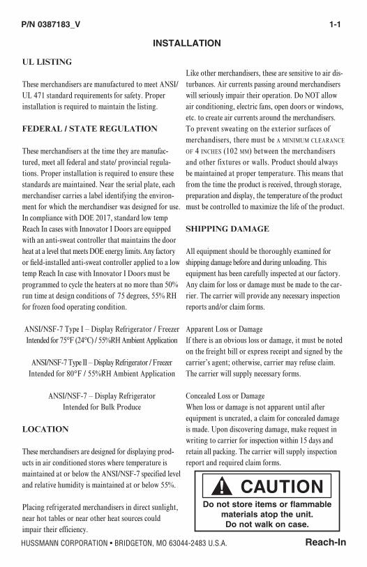
INSTALLATION
Do not store items or flammable materials atop the unit. Do not walk on case.

1-2 InstallatIon
P/N 0387183_V U.S. & Canada 1-800-922-1919 • Mexico 1-800-890-2900 • WWW.HUSSMANN.COM
EXTERIOR LOADING
Do NOT walk on top of merchandisers or damage to the merchandisers and serious personal injury could occur. They are noT sTrucTurally designed To supporT excessive exTernal loading such as the weight of a person. Do not store items or flammable materials atop the unit.
MERCHANDISERS SHIPPED WITH END INSTALLED
If the case was shipped with the end installed, two long bolts were used to hold the shipping brace to the end. If the shipping bolts are reinserted after remov-ing the brace, they will extend into the product area and may damage the coil. Therefore, be sure To replace These bolTs wiTh The shorTer bolTs provided.
Be careful not to damage the factory-installed end while moving the merchandiser. Make sure that tools are positioned past the end and beneath the merchan-diser’s support bar.
SHIPPING BRACES
Move the merchandiser as close as possible to its per-manent location and then remove all packaging. Check for damage before discarding packaging. Remove all separately packed accessories such as kits and shelves.
Locate the shipping block in the center of the heat exchanger (see illustration), and remove it before piping the merchandiser. This block was installed to minimize shipping vibration.
This product may contain chemicals known to the State of California to
cause cancer, birth defects, or other reproductive harm.
This warning is the result of the California State law known as the California Safe Drinking Water and Toxic Enforcement Act of 1986, which is commonly referred to as “Proposition 65.”
This warning does not mean that Hussmann prod-ucts will cause cancer or reproductive harm, or is in violation of any product-safety standards or require-ments. As clarified by the California State government, Proposition 65 can be considered more of a ‘right to know’ law than a pure product safety law. When used as designed, Hussmann believes that our products are not harmful. We provide the Proposition 65 warning to stay in compliance with California State law. It is your responsibility to provide accurate Proposition 65 warning labels to your customers when necessary. For more information on Proposition 65, please visit the California State government website.
For California Businesses:

Reach-In
P/N 0387183_V 1-3
HUSSMANN CORPORATION • BRIDGETON, MO 63044-2483 U.S.A.
MOVING MERCHANDISER THROUGH NARROW STORE ENTRANCES
Some exterior merchandiser parts may be disassembled for transit access through small doors or passage ways. This procedure takes approximately 30 minutes to disassemble and reassemble one case. Contact your Hussmann representative to see if store merchandisers have this kit option. The case height without these components installed on top is 82.75 in. (2102 mm). Case depth is 35.5 in. with handles, wireway pan and external frames removed.
Follow the steps below to decrease the merchandiser profile for narrow access:
1. Remove the door handles.
2. Remove the front bumper. Pull from the bottom and set aside.
3. Remove the lower front panel to access the wireway.
Remove Screws from Door Handle
Edge Fits over Wireway
Tabs fit in Retainer Slots
Front Panel
Remove Screws

1-4 InstallatIon
P/N 0387183_V U.S. & Canada 1-800-922-1919 • Mexico 1-800-890-2900 • WWW.HUSSMANN.COM
4. Remove the screws that attach the wireway pan to the bottom assembly.
5. Detach the rubber and plastic gromets from the wireway pan.
6. Remove the screws that attach the grounding lug to the wireway pan.
7. Slide the wireway pan out, and remove it from the case. Bumper brackets and supports are attached to wireway pan. Removing the pan will remove the entire assembly.
8. Remove the back, external braces from the rear of the case as shown below. Braces will slide straight back away from the case when nuts and screws are removed.
6 nuts and 1 bottom screw per
external brace
Bottom screw is located approximately 10 inches inboard from the rear of the case. Bottom screw location on removed rear brace.
Reach-In
P/N 0387183_V 1-5
HUSSMANN CORPORATION • BRIDGETON, MO 63044-2483 U.S.A.
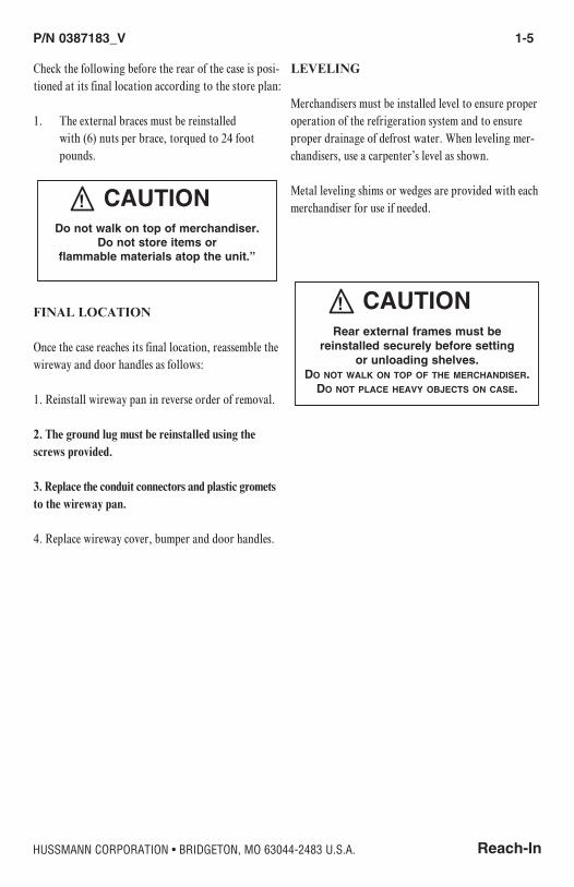
Check the following before the rear of the case is posi-tioned at its final location according to the store plan:
1. The external braces must be reinstalled with (6) nuts per brace, torqued to 24 foot pounds.
FINAL LOCATION
Once the case reaches its final location, reassemble the wireway and door handles as follows:
1. Reinstall wireway pan in reverse order of removal.
2. The ground lug must be reinstalled using the screws provided.
3. Replace the conduit connectors and plastic gromets to the wireway pan.
4. Replace wireway cover, bumper and door handles.
LEVELING
Merchandisers must be installed level to ensure proper operation of the refrigeration system and to ensure proper drainage of defrost water. When leveling mer-chandisers, use a carpenter’s level as shown.
Metal leveling shims or wedges are provided with each merchandiser for use if needed.
Rear external frames must be reinstalled securely before setting
or unloading shelves.Do not walk on top of the merchandIser.
do not place heavy objects on case.
Do not walk on top of merchandiser.Do not store items or
flammable materials atop the unit.”
1-6 InstallatIon
P/N 0387183_V U.S. & Canada 1-800-922-1919 • Mexico 1-800-890-2900 • WWW.HUSSMANN.COM
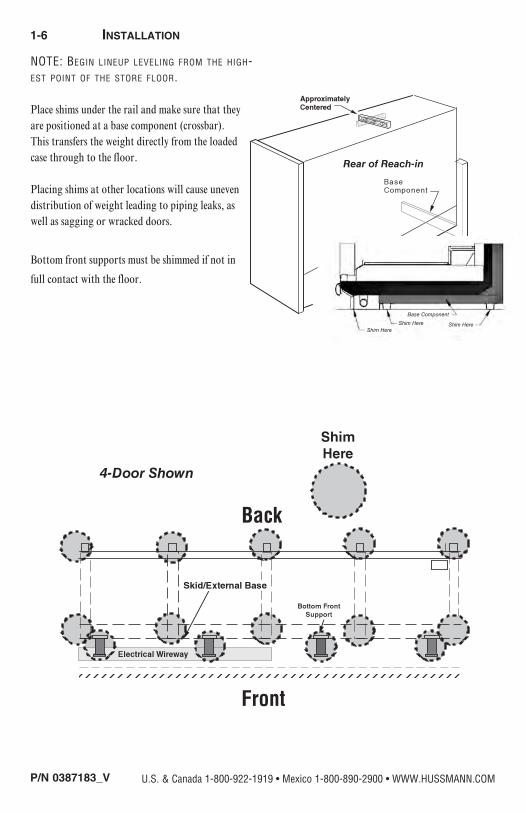
NOTE: Begin lineup leveling from the high-est point of the store floor.
Place shims under the rail and make sure that they are positioned at a base component (crossbar). This transfers the weight directly from the loaded case through to the floor.
Placing shims at other locations will cause uneven distribution of weight leading to piping leaks, as well as sagging or wracked doors.
Bottom front supports must be shimmed if not in
full contact with the floor.
Front
Back
Base Component
Shim Here Shim HereShim Here

Reach-In
P/N 0387183_V 1-7
HUSSMANN CORPORATION • BRIDGETON, MO 63044-2483 U.S.A.
DOOR ADJUSTMENT
After leveling and joining the merchandisers, adjust and level doors according to manufacturer’s instructions shipped with each product. Factory settings may be lost due to vibration during shipment.
JOINING
Sectional construction means that two or more mer-chandisers may be joined in line yielding one long continuous display requiring only one pair of ends. Joining kits and instructions are shipped with each merchandiser.
To join like fixtures, a joining kit is required. To join unlike fixtures, or like fixtures operating at dif-ferent temperatures, a 2 inch (51 mm) partition kit is required. To join same temperature merchandisers on different defrost cycles, a plexiglass partition kit is required.
all joinTs musT be air-TighT To prevenT formaTion of ice or condensaTion.
Refer to the instructions on the next page.
1-8 InstallatIon
P/N 0387183_V U.S. & Canada 1-800-922-1919 • Mexico 1-800-890-2900 • WWW.HUSSMANN.COM
PARTS LIST
Item
Quantity Description
RL/RM RLN RLNIM RMTM RM/RMF RMN RLNIE RLTM, RMTD1. 2 2 4 2 Donut Gasket2. 1 1 2 2 Gasket, .906 x 1/2 x 200 in.3. 1 1 2 1 Gasket, 1/2 x 1/4 x 600 in.4. 8 8 14 6 Cap Screw 5/16 -18 x 11/45. 8 8 14 6 Split Lock Washers 5/166. 1 1 2 1 Joint Molding7. 5 5 10 5 Binder Post and Screw8. 1 1 2 1 Splice Connector
Remote Reach-InsJoining Instructions
Joining Instructions
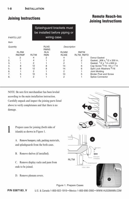
NOTE: Be sure first merchandiser has been leveled
according to the main installation instruction.
Carefully unpack and inspect the joining parts listed
above to verify completeness and that there is no
damage.
1 Prepare cases for joining (both sides of
islands) as shown in Figure 1.
A. Remove bumpers, rails, packing materials,
and splashguards from the both cases.
B. Remove shelves (if installed).
C. Remove display racks and pans from
ends to be joined.
D. Remove plenum covers.
Splashguard brackets must
be installed before piping or
wiring case.
B
A
C D
E
Figure 1. Prepare Cases
Bum per
Bum perRetainer
Splashguard
SIDE VIEW
A
RLTM
C
RLNSRMNS
RLTIM44212122102
Reach-In
P/N 0387183_V 1-9
HUSSMANN CORPORATION • BRIDGETON, MO 63044-2483 U.S.A.
PARTS LIST
Item
Quantity Description
RL/RM RLN RLNIM RMTM RM/RMF RMN RLNIE RLTM, RMTD1. 2 2 4 2 Donut Gasket2. 1 1 2 2 Gasket, .906 x 1/2 x 200 in.3. 1 1 2 1 Gasket, 1/2 x 1/4 x 600 in.4. 8 8 14 6 Cap Screw 5/16 -18 x 11/45. 8 8 14 6 Split Lock Washers 5/166. 1 1 2 1 Joint Molding7. 5 5 10 5 Binder Post and Screw8. 1 1 2 1 Splice Connector
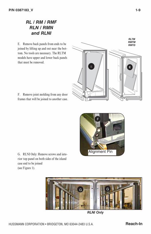
E. Remove back panels from ends to be joined by lifting up and out near the bot-tom. No tools are necessary. The RLTM models have upper and lower back panels that must be removed.
F. Remove joint molding from any door frames that will be joined to another case.
G. RLNI Only: Remove screws and inte-rior top panel on both sides of the island case end to be joined
(see Figure 1).
E
G G
RLNI Only
Alignment Pin
F
E
RL / RM / RMFRLN / RMN and RLNI
RLTMRMTMRMTD
1-10 InstallatIon
P/N 0387183_V U.S. & Canada 1-800-922-1919 • Mexico 1-800-890-2900 • WWW.HUSSMANN.COM
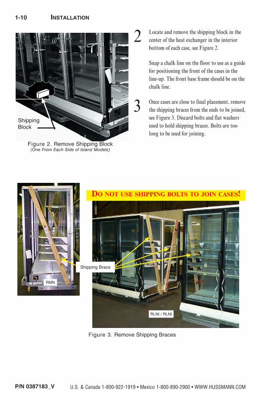
2 Locate and remove the shipping block in the center of the heat exchanger in the interior bottom of each case, see Figure 2.
Snap a chalk line on the floor to use as a guide for positioning the front of the cases in the line-up. The front base frame should be on the chalk line.
3 Once cases are close to final placement, remove the shipping braces from the ends to be joined, see Figure 3. Discard bolts and flat washers used to hold shipping braces. Bolts are too long to be used for joining.
RMN
Figure 3. Remove Shipping Braces
Do not use shipping bolts to join cases!
Shipping Brace
Figure 2. Remove Shipping Block(One From Each Side of Island Models)
ShippingBlock
RLNI / RLNI

Reach-In
P/N 0387183_V 1-11
HUSSMANN CORPORATION • BRIDGETON, MO 63044-2483 U.S.A.
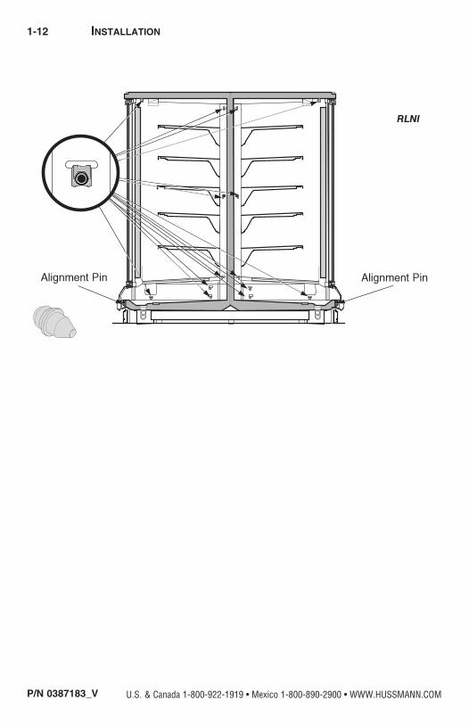
4 If not already installed make sure Nut Retainers and Alignment Pins are in place in the right end frame as shown in Figure 4A or 4B.
Figure 4A. Verify Nut Retainer Installation
Factory InstalledNut Retainer
RLT has no Alignment Pin
RLTMRMTM
RL / RM / RMFand
RLN / RMN
Alignment Pin
1-12 InstallatIon
P/N 0387183_V U.S. & Canada 1-800-922-1919 • Mexico 1-800-890-2900 • WWW.HUSSMANN.COM
RLNI
Reach-In
P/N 0387183_V 1-13
HUSSMANN CORPORATION • BRIDGETON, MO 63044-2483 U.S.A.
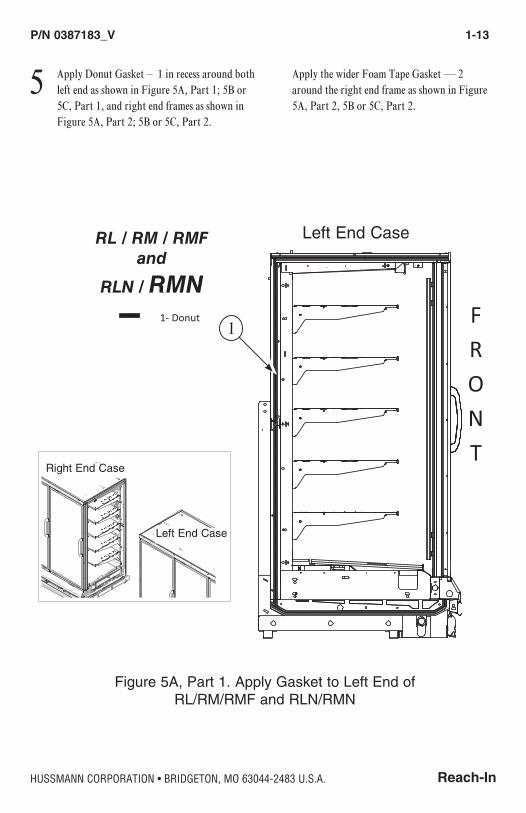
5 Apply Donut Gasket – 1 in recess around both left end as shown in Figure 5A, Part 1; 5B or 5C, Part 1, and right end frames as shown in Figure 5A, Part 2; 5B or 5C, Part 2.
Apply the wider Foam Tape Gasket — 2 around the right end frame as shown in Figure 5A, Part 2, 5B or 5C, Part 2.
Figure 5A, Part 1. Apply Gasket to Left End of RL/RM/RMF and RLN/RMN
RL / RM / RMFand
RLN / RMNFRONT
Right End Left End
FRONT
Pad Shoe Sealer
1- Donut2- 1 in x in3- in x in
Use all three gasketsWhen applying an endassembly.
Left End Case
FRONT
Right End Left End
FRONT
Pad Shoe Sealer
1- Donut2- 1 in x in3- in x in
Use all three gasketsWhen applying an endassembly. Left End Case
Right End Case
FRONT
Right End Left End
FRONT
Pad Shoe Sealer
1- Donut2- 1 in x in3- in x in
Use all three gasketsWhen applying an endassembly.
1
1-14 InstallatIon
P/N 0387183_V U.S. & Canada 1-800-922-1919 • Mexico 1-800-890-2900 • WWW.HUSSMANN.COM
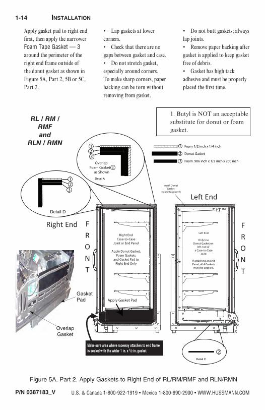
Figure 5A, Part 2. Apply Gaskets to Right End of RL/RM/RMF and RLN/RMN
RL / RM / RMFand
RLN / RMN
Apply gasket pad to right end first, then apply the narrower Foam Tape Gasket — 3 around the perimeter of the right end frame outside of the donut gasket as shown in Figure 5A, Part 2, 5B or 5C, Part 2.
• Lap gaskets at lower corners. • Check that there are no gaps between gasket and case. • Do not stretch gasket, especially around corners. To make sharp corners, paper backing can be torn without removing from gasket.
• Do not butt gaskets; always lap joints. • Remove paper backing after gasket is applied to keep gasket free of debris.
• Gasket has high tack adhesive and must be properly placed the first time.
OverlapGasket
Gasket Pad
FRONT
Right End
Left End
FRONT
/ / / / / / /
///////////////////////////// 23
/////////////////////////////
Detail D
1
Overlap Foam Gasket 3
as Shown
/////////////////////////////
123
/////////////////////////////
Detail A
/ / / / / / / /
/////////////////////////////
1
2
3
Donut Gasket
Foam .906 inch x 1/2 inch x 200 inch
Foam 1/2 inch x 1/4 inch
Right EndCase-to-Case
Joint or End Panel
Apply Donut Gasket,Foam Gaskets
and Gasket Pad toRight End Only
Apply Gasket Pad
2Detail C
Install Donut Gasket
(seat into groove)
Left End
Only UseDonut Gasket on
left end of a Case-to-Case
Joint
If attaching an EndPanel, all 4 Gaskets
must be applied.
1. Butyl is NOT an acceptable substitute for donut or foam gasket.
Gasket Pad

Reach-In
P/N 0387183_V 1-15
HUSSMANN CORPORATION • BRIDGETON, MO 63044-2483 U.S.A.
Figure 5A. Apply Gaskets to Left End of RLNI
RLNI
Left End Case
Gasket Pad

1-16 InstallatIon
P/N 0387183_V U.S. & Canada 1-800-922-1919 • Mexico 1-800-890-2900 • WWW.HUSSMANN.COM
1 in. x in.
in. x in.
Figure 5B. Apply Gaskets to Right End of RLNI
RLNIRight End Case
Gasket Pad

Reach-In
P/N 0387183_V 1-17
HUSSMANN CORPORATION • BRIDGETON, MO 63044-2483 U.S.A.
Figure 5C, Part 1. Apply Donut Gasket to Left End of RLTM / RMTM /
FRONT
Right EndCase-to-Case
Joint or End Panel
Apply Donut Gasket,Foam Gaskets
and Gasket Pad toRight End Only
FRONT
Left End
Only UseDonut Gasket on
left end of a Case-to-Case
Joint
If attaching an EndPanel, all 4 Gaskets
must be applied.Install Donut
Gasket as Shown(seat into groove)
Apply Unitized Gasket Pad (4)
Unitized Gasket Pad
////////////////////////////////////////////////////////////////////////////////////////////////////////////////////////////////////////////////////////////////////////////////////////////////////////////////////////////////////////////////////////
/ / / / ~/ / / / / / / / / / / / / / / / / / / / / / / / / / / / / / / / / / / / / / / / / / / / / / / / / / / / / / / / / / / / / / / / / / / / / / / / / / / / / / / / / / / / / /
/ /
/ /
~/ /
/ /
/ /
/ /
/ /
/ /
/ /
/ /
/ /
/ /
/ /
/ /
/ /
/ /
/ /
/ /
/ /
/ /
/ /
/ /
/ /
/ /
/ /
/ /
/ /
/ /
/ /
/ /
/ /
/ /
/ /
/ /
/ /
/ /
/ /
/ /
/ /
/ /
/ /
/ /
/ /
/ /
/ /
////////////////////////////////////////////////////////////////////////////////////////////////////////////////////////////////////////////////////////////////////////////////////////////////////////////////////////////////////////////////////////
Overlap Foam Gasket 3
as Shown
/ / / / / / / /
/////////////////////////////
123
/ / / / / / / / / / / / / / / / / / / / / / / / / / / / / / / / / / / / / / / / / / / / / / / / / / / / / / / / / / / / / / / / / / / / / / / / / / / / / / / / / / / / / / / / / /
////////////////////////////////////////////////////////////////////////////////////////////////////////////////////////////////////////////////////////////////////////////////////////////////////////////////////////////////////////////////////////
/ / / / / / / / / / / / / / / / / / / / / / / / / / / / / / / /
/ / / / / / / / / / / / / / / / / / / / / / / /
/ / / / / / / / / / / / / / / / / ~ / / /
/ / / / / / / /
/////////////////////////////
1
2
3
Donut Gasket
Foam 1 inch x 1/2 inch
Foam 1/2 inch x 1/4 inch
Install Donut Gasket as Shown
/////////////////////////////
Install Donut Gasket
(seat into groove)
Install Donut Gasket
(seat into groove)
////////////////////////////////////////////////////////////////////////////////////////////////////////////////////////////////////////////////////////////////////////////////////////////////////////////////////////////////////////////////////////
Gasket 3must overlap
Gasket 3
/ / / / / / / /
/////////////////////////////
Detail A
Detail B
Gasket 3must overlap at all intersections — Do not butt gaskets.
123
2Detail C
Only Foam GasketNumber 3
/ / / / / / /
///////////////////////////// 23
/////////////////////////////
Detail D
1
Left End Case
Pad Shoe Sealer
FRONT
FRONT
Left EndRight End
1- Donut2- 1 in x in3- in x in
Use all three gasketsWhen applying an endassembly
Left End Case
Right End Case
RLTMRMTMRMTD
1-18 InstallatIon
P/N 0387183_V U.S. & Canada 1-800-922-1919 • Mexico 1-800-890-2900 • WWW.HUSSMANN.COM
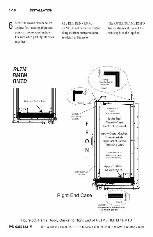
6 Move the second merchandiser against first, mating alignment pins with corresponding holes. Use care when pushing the cases together.
RL / RM / RLN / RMN / RLNI: Do not cut wires routed along the front bumper retainer. See detail in Figure 6.
The RMTM / RLTM / RMTD has no alignment pin and the wireway is at the top front.
Figure 5C, Part 2. Apply Gasket to Right End of RLTM / RMTM / RMTD
RLTMRMTMRMTD
FRONT
Right EndCase-to-Case
Joint or End Panel
Apply Donut Gasket,Foam Gaskets
and Gasket Pad toRight End Only
FRONT
Left End
Only UseDonut Gasket on
left end of a Case-to-Case
Joint
If attaching an EndPanel, all 4 Gaskets
must be applied.Install Donut
Gasket as Shown(seat into groove)
Apply Unitized Gasket Pad (4)
Unitized Gasket Pad
////////////////////////////////////////////////////////////////////////////////////////////////////////////////////////////////////////////////////////////////////////////////////////////////////////////////////////////////////////////////////////
/ / / / ~/ / / / / / / / / / / / / / / / / / / / / / / / / / / / / / / / / / / / / / / / / / / / / / / / / / / / / / / / / / / / / / / / / / / / / / / / / / / / / / / / / / / / / /
/ /
/ /
~/ /
/ /
/ /
/ /
/ /
/ /
/ /
/ /
/ /
/ /
/ /
/ /
/ /
/ /
/ /
/ /
/ /
/ /
/ /
/ /
/ /
/ /
/ /
/ /
/ /
/ /
/ /
/ /
/ /
/ /
/ /
/ /
/ /
/ /
/ /
/ /
/ /
/ /
/ /
/ /
/ /
/ /
/ /
////////////////////////////////////////////////////////////////////////////////////////////////////////////////////////////////////////////////////////////////////////////////////////////////////////////////////////////////////////////////////////
Overlap Foam Gasket 3
as Shown
/ / / / / / / /
/////////////////////////////
123
/ / / / / / / / / / / / / / / / / / / / / / / / / / / / / / / / / / / / / / / / / / / / / / / / / / / / / / / / / / / / / / / / / / / / / / / / / / / / / / / / / / / / / / / / / /
////////////////////////////////////////////////////////////////////////////////////////////////////////////////////////////////////////////////////////////////////////////////////////////////////////////////////////////////////////////////////////
/ / / / / / / / / / / / / / / / / / / / / / / / / / / / / / / /
/ / / / / / / / / / / / / / / / / / / / / / / /
/ / / / / / / / / / / / / / / / / ~ / / /
/ / / / / / / /
/////////////////////////////
1
2
3
Donut Gasket
Foam 1 inch x 1/2 inch
Foam 1/2 inch x 1/4 inch
Install Donut Gasket as Shown
/////////////////////////////
Install Donut Gasket
(seat into groove)
Install Donut Gasket
(seat into groove)
////////////////////////////////////////////////////////////////////////////////////////////////////////////////////////////////////////////////////////////////////////////////////////////////////////////////////////////////////////////////////////
Gasket 3must overlap
Gasket 3
/ / / / / / / /
/////////////////////////////
Detail A
Detail B
Gasket 3must overlap at all intersections — Do not butt gaskets.
123
2Detail C
Only Foam GasketNumber 3
/ / / / / / /
///////////////////////////// 23
/////////////////////////////
Detail D
1
FRONT
Right EndCase-to-Case
Joint or End Panel
Apply Donut Gasket,Foam Gaskets
and Gasket Pad toRight End Only
FRONT
Left End
Only UseDonut Gasket on
left end of a Case-to-Case
Joint
If attaching an EndPanel, all 4 Gaskets
must be applied.Install Donut
Gasket as Shown(seat into groove)
Apply Unitized Gasket Pad (4)
Unitized Gasket Pad
////////////////////////////////////////////////////////////////////////////////////////////////////////////////////////////////////////////////////////////////////////////////////////////////////////////////////////////////////////////////////////
/ / / / ~/ / / / / / / / / / / / / / / / / / / / / / / / / / / / / / / / / / / / / / / / / / / / / / / / / / / / / / / / / / / / / / / / / / / / / / / / / / / / / / / / / / / / / /
/ /
/ /
~/ /
/ /
/ /
/ /
/ /
/ /
/ /
/ /
/ /
/ /
/ /
/ /
/ /
/ /
/ /
/ /
/ /
/ /
/ /
/ /
/ /
/ /
/ /
/ /
/ /
/ /
/ /
/ /
/ /
/ /
/ /
/ /
/ /
/ /
/ /
/ /
/ /
/ /
/ /
/ /
/ /
/ /
/ /
////////////////////////////////////////////////////////////////////////////////////////////////////////////////////////////////////////////////////////////////////////////////////////////////////////////////////////////////////////////////////////
Overlap Foam Gasket 3
as Shown
/ / / / / / / /
/////////////////////////////
123
/ / / / / / / / / / / / / / / / / / / / / / / / / / / / / / / / / / / / / / / / / / / / / / / / / / / / / / / / / / / / / / / / / / / / / / / / / / / / / / / / / / / / / / / / / /
////////////////////////////////////////////////////////////////////////////////////////////////////////////////////////////////////////////////////////////////////////////////////////////////////////////////////////////////////////////////////////
/ / / / / / / / / / / / / / / / / / / / / / / / / / / / / / / /
/ / / / / / / / / / / / / / / / / / / / / / / /
/ / / / / / / / / / / / / / / / / ~ / / /
/ / / / / / / /
/////////////////////////////
1
2
3
Donut Gasket
Foam 1 inch x 1/2 inch
Foam 1/2 inch x 1/4 inch
Install Donut Gasket as Shown
/////////////////////////////
Install Donut Gasket
(seat into groove)
Install Donut Gasket
(seat into groove)
////////////////////////////////////////////////////////////////////////////////////////////////////////////////////////////////////////////////////////////////////////////////////////////////////////////////////////////////////////////////////////
Gasket 3must overlap
Gasket 3
/ / / / / / / /
/////////////////////////////
Detail A
Detail B
Gasket 3must overlap at all intersections — Do not butt gaskets.
123
2Detail C
Only Foam GasketNumber 3
/ / / / / / /
///////////////////////////// 23
/////////////////////////////
Detail D
1
Right End Case

Reach-In
P/N 0387183_V 1-19
HUSSMANN CORPORATION • BRIDGETON, MO 63044-2483 U.S.A.
Figure 6. Move Cases Together
R L or R MR LN or R MN
R LNI
Do not cut wires in bumper retainer.

1-20 InstallatIon
P/N 0387183_V U.S. & Canada 1-800-922-1919 • Mexico 1-800-890-2900 • WWW.HUSSMANN.COM
Figure 7A. Joining Sequence
RL, RM, RMF, RLN, RMN
D
EC
B
A
5
4
Nut Retainer
Figure 7B. Joining Sequence
RLTM / RMTM / RMTD
7 Loosely insert Cap Screw – 5 with Lock Washer – 6 into each nut retainer follow-ing the sequence shown in Figures 7A and 7B. Do not tighten fully.
A. Fasten bottom fronts together, but tight-en only until front panels touch.
B. Move to the bottom back position and join (2 places).
C. Join at the top front position.
D. Go to the middle back wall position and join.
E. Join at the lower back wall.
F. Finally, join at the top back wall posi-tion.
Following the same sequence, tighten each cap screw fully until the merchandisers are joined with a snug fit and gaskets are compressed.
When joining two RLNIE models, nut retainers and alignment pins are used on one case only.
8 Refer to Section 1 of the Reach-In Installation and Service Manual to install splashguard brackets and bumpers. Section 3 provides direction for installing splash-guards, including splashguard Splice Connector – 8. shown in Figure 9. Note that RLTM / RMTM cases have steel splashguards that do not use a splice con-nector.

Reach-In
P/N 0387183_V 1-21
HUSSMANN CORPORATION • BRIDGETON, MO 63044-2483 U.S.A.
A
Alignment P in
R LNI
A
Alignment P in
E
B
Nut R etainer
6
5
F
D
C
RLNI
Figure 7C. Joining Sequence for RLNIM Cases
1-22 InstallatIon
P/N 0387183_V U.S. & Canada 1-800-922-1919 • Mexico 1-800-890-2900 • WWW.HUSSMANN.COM
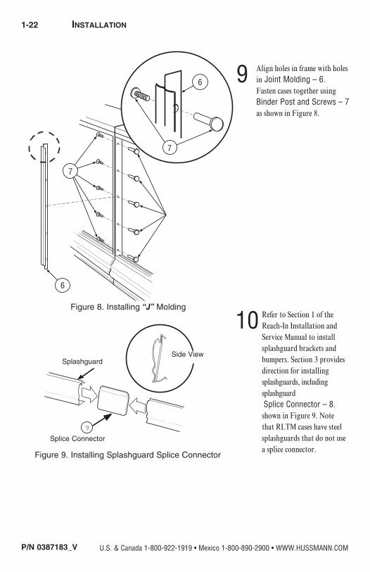
9 Align holes in frame with holes in Joint Molding – 6. Fasten cases together using Binder Post and Screws – 7 as shown in Figure 8.
10 Refer to Section 1 of the Reach-In Installation and Service Manual to install splashguard brackets and bumpers. Section 3 provides direction for installing splashguards, including splashguard Splice Connector – 8. shown in Figure 9. Note that RLTM cases have steel splashguards that do not use a splice connector.
6
7
7
6
Figure 8. Installing “J” Molding
Figure 9. Installing Splashguard Splice Connector
Splice Connector
SplashguardSIDE VIEW
9
Splashguard
Splice Connector
Side View

Reach-In
P/N 0387183_V 1-23
HUSSMANN CORPORATION • BRIDGETON, MO 63044-2483 U.S.A.
INSTALLING SPLASHGUARD BRACKETS (RL/ RLN)
1. Attach retainer splashguard RI to bracket support splashguard RL & RM using three screws
2. insTall splashguard supporT brackeTs before piping case. The leveling brackets have a maximum extension of one (1) inch (25 mm) for uneven floors.
DO NOT place shims under splashguard brackeTs.

1-24 InstallatIon
P/N 0387183_V U.S. & Canada 1-800-922-1919 • Mexico 1-800-890-2900 • WWW.HUSSMANN.COM
INSTALLING SPLASHGUARDS AND BRACKETS
(RLTM Cases)
To install splashguards and brackets:
1. Slide the splashguard support bracket’s small
flange into base rail slots. Next, slide the splashguard
retainer assembly under the case as shown.
2. Rotate the retainer assembly clockwise (from right
hand side) while pulling towards the front of the case,
until the forward most flange sits flush with the back
of the color panel.
3. Align the retainer assembly with and attach to the
support bracket using #10 screws. Then install a #8
screw through the color panel into the top retainer
flange.
DO NOT place shims under splashguard brackeTs.
Splashguards Installation
Splashguard
Splice Connector
Side Detail
R LNS 5 A
1. S lide the splashguard support bracket's small flange into the
s lots in the base rail. Then s lide the splashguard retainer
assembly under the case as shown.
2. R otate the retainer assembly clockwise (from right hand side)
while pulling towards the front of the case until the forward
most flange s its flush with the back of the color panel.
3. Align the retainer assembly with and attach to the support
bracket us ing #10 screws. Then install a #8 screw through the
color panel into the top retainer flange.
R LNS 5 A
1. S lide the splashguard support bracket's small flange into the
s lots in the base rail. Then slide the splashguard retainer
assembly under the case as shown.
2. R otate the retainer assembly clockwise (from right hand side)
while pulling towards the front of the case until the forward
most flange s its flush with the back of the color panel.
3. Align the retainer assembly with and attach to the support
bracket us ing #10 screws. Then install a #8 screw through the
color panel into the top retainer flange.
R LNS 5 A
1. S lide the splashguard support bracket's small flange into the
s lots in the base rail. Then s lide the splashguard retainer
assembly under the case as shown.
2. R otate the retainer assembly clockwise (from right hand side)
while pulling towards the front of the case until the forward
most flange s its flush with the back of the color panel.
3. Align the retainer assembly with and attach to the support
bracket us ing #10 screws. Then install a #8 screw through the
color panel into the top retainer flange.
1.
2.
3.
Reach-In
P/N 0387183_V 1-25
HUSSMANN CORPORATION • BRIDGETON, MO 63044-2483 U.S.A.
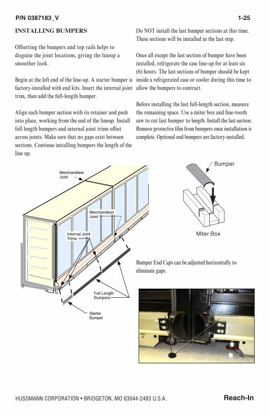
INSTALLING BUMPERS
Offsetting the bumpers and top rails helps to disguise the joint locations, giving the lineup a smoother look.
Begin at the left end of the line-up. A starter bumper is factory-installed with end kits. Insert the internal joint trim, then add the full-length bumper.
Align each bumper section with its retainer and push into place, working from the end of the lineup. Install full length bumpers and internal joint trims offset across joints. Make sure that no gaps exist between sections. Continue installing bumpers the length of the line up.
Do NOT install the last bumper sections at this time. These sections will be installed in the last step.
Once all except the last section of bumper have been installed, refrigerate the case line-up for at least six (6) hours. The last sections of bumper should be kept inside a refrigerated case or cooler during this time to allow the bumpers to contract.
Before installing the last full-length section, measure the remaining space. Use a miter box and fine-tooth saw to cut last bumper to length. Install the last section. Remove protective film from bumpers once installation is complete. Optional end bumpers are factory-installed.
Bumper End Caps can be adjusted horizontally to eliminate gaps.


Reach-In
P/N 0387183_V 2-1
HUSSMANN CORPORATION • BRIDGETON, MO 63044-2483 U.S.A.
REFRIGERANT
The correct type of refrigerant will be stamped on each merchandiser’s serial plate which is located on the left-hand end of the interior top liner.
REFRIGERANT PIPING
Standard Connection LocationThe refrigerant line connections are at the right- hand end of merchandiser (end opposite the main serial plate) beneath the display pans. A sticker marks the location of the connection. The installer must saw a hole to exit the cases.
A refrigeration shroud ships with each case. Be fore making connections, place the refrigeration shroud over refrigeration piping so that when the shroud is rotated into place, it will be in the upright position. The Figure 2-1 shows the correct orientation.
Be careful not to burn, scorch or overheat the shroud when making connections. Once connections have been made, apply silicone sealant to the bottom of the shroud as shown in Figure 2-2.
REFRIGERATION / ELECTRICAL
When brazing pipes be sure to use the insulation blanket shipped with the merchandiser to prevent damage to
the plastic case bottom.
Refrigeration lines are under pressure. Depressurize and recover refrigerant before attempting any connection or repair.
Refrigerant vapor is hazardous to your health and can cause death. Avoid breathing refrigerant and lubrication vapor or mist. Exposure may irritate eyes, nose and throat. If accidental system discharge occurs, ventilate work area before resuming service.
Always wear safety goggles and protective gloves when working with refrigerants. Contact with refrigerant may cause injury. Disconnect hoses with extreme caution! All hoses may contain liquid refrigerant under pressure.
Be sure that any room where you are working is thoroughly ventilated, especially if a leak is suspected.
Read all safety information regarding the safe handling of refrigerant and refrigerant oil, including the Material Safety Data Sheet. MSDS sheets can be obtained from your refrigerant supplier.
Figure 2-2
Figure 2-1

2-2 RefRigeRation / electRical
P/N 0387183_V U.S. & Canada 1-800-922-1919 • Mexico 1-800-890-2900 • WWW.HUSSMANN.COM
As shown in Figure 2-3, rotate and center the shroud over the refrigeration outlet foam pad.
Seal this outlet thoroughly. Seal both the inside and the outside. We recommend using an expanding polyurethane foam insulation. Cover foam with silicone to prevent water from entering foam.
Optional Internal Top Piping ConnectionsA shroud should be used to seal outside pipe penetrations at the top of the merchandiser. Position the shroud over the case piping before making the final connection.
Once all connections are made and insulation has been applied to the piping, run a bead of sealant around the bottom of the shroud. Put the shroud into position and attach with six screws.
In the event the shroud was not placed over the piping prior to final connection, the shroud can be cut (carefully) and then installed with adhesive holding the shroud in place on top of the merchandiser.
After connections have been made, seal this outlet thoroughly. Seal both the inside and the outside. We recommend using an expanding polyurethane foam insulation. Cover foam with silicone to ensure seal around insulation and to prevent deterioration of foam.
Figure 2-3
Reach-In
P/N 0387183_V 2-3
HUSSMANN CORPORATION • BRIDGETON, MO 63044-2483 U.S.A.
MultiplexingPiping of merchandisers operating on the same refrigeration system may be run from merchan diser to merchandiser through the end frame saddles provided for this purpose. Do NoT ruN refrigeraNT liNes Through merchaNDisers ThaT are NoT oN The same refrigeraTioN sysTem as this may result in poor refrigeration control and compressor failure.
NOTE: If Gas defrost is used, the liquid line will need to be increased two sizes larger inside the merchandiser area. This is necessary to ensure even liquid drainage from all evaporators during defrost.
Line SizingRefrigerant lines should be sized as shown on the refrigeration legend that is furnished for the store or according to ASHRAE guidelines.
Oil TrapsP-traps (oil traps) must be installed at the base of all suction line vertical risers.
Pressure DropPressure drop can rob the system of capacity. To keep the pressure drop to a minimum, keep the refrigerant line run as short as possible using a minimum number of elbows. Where elbows are required, use loNg raDius elbows oNly.
INSULATION
With GAS DefrostThe suction and liquid lines should NOT contact each other and should be insulated separately for a minimum of 30 ft (9144 mm) from the merchandiser.
With OTHER Than Gas DefrostThe suction and liquid lines should be clamped or taped together and insulated for a minimum of 30 ft (9144 mm) from the merchandiser.
With All DefrostAdditional insulation for the balance of the liquid and suction lines is recommended wherever condensation drippage is objectionable or the lines are exposed to ambient conditions.
2-4 RefRigeRation / electRical
P/N 0387183_V U.S. & Canada 1-800-922-1919 • Mexico 1-800-890-2900 • WWW.HUSSMANN.COM
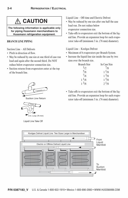
BRANCH LINE PIPING
Suction Line – All Defrosts • Pitch in direction of flow.• May be reduced by one size at one third of case run
load and again after the second third. Do NOT reduce below evaporator connection size.
• Suction returns from evaporators enter at the top of the branch line.
Liquid Line – Off-time and Electric Defrost• May be reduced by one size after one half the case
load run. Do not reduce below evaporator connection size.
• Take-offs to evaporators exit the bottom of the liq-uid line. Provide an expansion loop for each evapo-rator take-off (minimum 3 in. (76 mm) diameter).
Liquid Line – Koolgas Defrost• Maximum of 6 evaporators per Branch System.• Increase the liquid line size inside the case by two
sizes over the branch size. Branch Size In Case Size 1/2 7/8 5/8 1 1/8 7/8 1 3/8 1 1/8 1 5/8 1 3/8 2 1/8
• Take-offs to evaporators exit the bottom of the liq-uid line. Provide an expansion loop for each evapo-rator take-off (minimum 3 in. (76 mm) diameter).
The following information is applicable only for piping Hussmann merchandisers to
Hussmann refrigeration equipment.
Reach-In
P/N 0387183_V 2-5
HUSSMANN CORPORATION • BRIDGETON, MO 63044-2483 U.S.A.
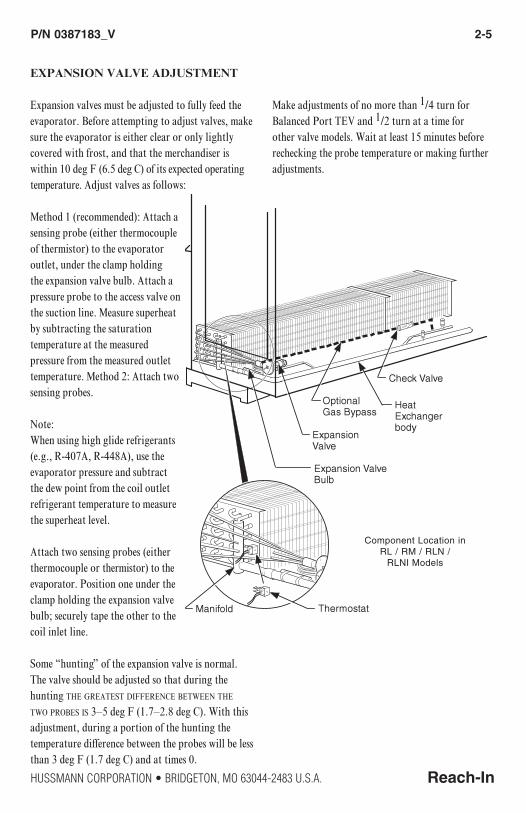
EXPANSION VALVE ADJUSTMENT
Expansion valves must be adjusted to fully feed the evaporator. Before attempting to adjust valves, make sure the evaporator is either clear or only lightly covered with frost, and that the merchandiser is within 10 deg F (6.5 deg C) of its expected operating temperature. Adjust valves as follows:
Method 1 (recommended): Attach a sensing probe (either thermocouple of thermistor) to the evaporator outlet, under the clamp holding the expansion valve bulb. Attach a pressure probe to the access valve on the suction line. Measure superheat by subtracting the saturation temperature at the measured pressure from the measured outlet temperature. Method 2: Attach two sensing probes.
Note: When using high glide refrigerants (e.g., R-407A, R-448A), use the evaporator pressure and subtract the dew point from the coil outlet refrigerant temperature to measure the superheat level.
Attach two sensing probes (either thermocouple or thermistor) to the evaporator. Position one under the clamp holding the expansion valve bulb; securely tape the other to the coil inlet line.
Some “hunting” of the expansion valve is normal. The valve should be adjusted so that during the hunting The greaTesT DiffereNce beTweeN The Two probes is 3–5 deg f (1.7–2.8 deg c). With this adjustment, during a portion of the hunting the temperature difference between the probes will be less than 3 deg F (1.7 deg c) and at times 0.
Make adjustments of no more than 1/4 turn for Balanced Port TEV and 1/2 turn at a time for other valve models. Wait at least 15 minutes before re checking the probe temperature or making further adjustments.
Component Location in RL / RM / RLN /
RLNI Models

2-6 RefRigeRation / electRical
P/N 0387183_V U.S. & Canada 1-800-922-1919 • Mexico 1-800-890-2900 • WWW.HUSSMANN.COM
REFRIGERATION THERMOSTAT
The thermostat body is located in the electrical race-way near the right-hand end of the merchan diser. Its sensing bulb is located behind the right end interior back panel.
M
M
M
(Right end of Case)
Defrost TerminationThermostat Location
2 Door RLTM
3, 4 & 5 Door RLTM
(Left end of Case)

Reach-In
P/N 0387183_V 2-7
HUSSMANN CORPORATION • BRIDGETON, MO 63044-2483 U.S.A.
DEFROST TERMINATION THERMOSTAT
The standard disc type defrost termination thermostat is not adjustable.
On low-temperature merchandisers, the defrost termination thermostat or optional termination sensor is located on the right end of the coil at the bottom center return bend. If an optional adjustable thermostat is used, the bulb will be clamped to the suction line on the left end of the merchandiser.
CONTROL SETTINGSMEDIUM TEMPERATURE
Conventional Single CompressorMeasure Discharge Air Temperatureat the center of the caseat the discharge honeycomb.
Merchandiser temperature must be controlled by a thermostat or other device with a 3–6 deg F (1.7–3.3 deg C) differential. It will be wired to control the compressor motor contactor.
Standard Off Time defrost is time terminated. On outdoor units the defrost timer will control a liquid line solenoid beginning a defrost pumpdown 4 minutes before defrost.
The defrost frequency and lengths listed may require adjustment for specific store conditions. Factors include: Store temperature and humidity Low head pressure Long refrigerant line runs Seasonal changes Merchandiser temperature lower than recommended
When practical, defrost when store is closed.
Low pressure control settings are applicable to outdoor condensing units where ambient does not fall below 0 deg F.
CONTROL SETTINGSLOW TEMPERATURE
Conventional Single CompressorMeasure Discharge Air Temperatureat the center of the caseat the discharge honeycomb.
Merchandiser temperature must be controlled by a thermostat or other device with a 3–6 deg F (1.7–3.3 deg C) differential. It will be wired to control the compressor motor contactor.
Standard Electric defrost is temperature terminated. The defrost termination thermostats for all the merchandisers on one compressor are wired in series. Failsafe must not control defrost cycle length, especially when less than 208V power supply is used for defrost heaters, or if frost build up is heavy from shopping demands.
On outdoor units the defrost timer will control a liq-uid line solenoid beginning a defrost pumpdown 4 minutes before defrost.
Optional Gas defrost is time terminated and has fan cycling thermostat. The defrost frequency and lengths listed may require adjustment for specific store conditions. Factors include: Store temperature and humidity Low head pressure Long refrigerant line runs Seasonal changes Merchandiser temperature lower than recommended

2-8 RefRigeRation / electRical
P/N 0387183_V U.S. & Canada 1-800-922-1919 • Mexico 1-800-890-2900 • WWW.HUSSMANN.COM
Defrost after store closes when practical.Low pressure control settings are applicable to outdoor condensing units where ambient does not fall below 0 deg F.
CONTROL SETTINGSMEDIUM TEMPERATURE
Parallel Compressor RackMeasure Discharge Air Temperatureat the center of the caseat the discharge honeycomb.
Merchandiser temperature must be controlled by a mechanical or electronic pressure regulator or thermostat that will be mounted on the rack.
Standard Off Time defrost is time terminated. The defrost frequency and lengths listed may require adjustment for specific store conditions. Factors include: Store temperature and humidity Low head pressure Long refrigerant line runs Seasonal changes Merchandiser temperature lower than recommended
Stagger defrosts to maintain stable compressor loading and sufficient defrost gas. When practical, defrost when store is closed.
CONTROL SETTINGSLOW TEMPERATURE
Parallel Compressor RackMeasure Discharge Air Temperatureat the center of the caseat the discharge honeycomb.
Merchandiser temperature must be controlled by a mechanical or electronic pressure regulator or thermostat that will be mounted on the rack.
Standard Electric defrost is temperature terminated. Failsafe must not control defrost cycle length, especially when less than 208V power supply is used for defrost heaters, or if frost build up is heavy from shopping demands.
Optional Gas defrost is time terminated and has fan cycling thermostat. The defrost frequency and lengths listed may require adjustment for specific store conditions. Factors include: Store temperature and humidity Low head pressure Long refrigerant line runs Seasonal changes Merchandiser temperature lower than recommendedStagger defrosts to maintain stable compressor loading and sufficient defrost gas. When practical, defrost when store is closed.

Reach-In
P/N 0387183_V 2-9
HUSSMANN CORPORATION • BRIDGETON, MO 63044-2483 U.S.A.
MERCHANDISER ELECTRICAL DATA
Merchandiser data sheets for specific models are shipped with this manual. The data sheets provide merchandiser electrical data, standard electrical schematics, parts lists and performance data. Refer to the merchandiser data sheets and merchandiser serial plate for electrical information. Refer to the separate wiring diagrams shipped with the case for specific information about the merchandiser and any optional wiring kits that may have been applied.
FIELD WIRING
Field wiring must be sized for component amperes stamped on the serial plate. Actual ampere draw may be less than specified. Field wiring from the refrigeration control panel to the merchandisers is required for defrost termination thermostats and for optional refrigeration thermostats. When multiple merchandisers are on the same defrost circuit, the defrost termination thermostats are wired in series.
ALWAYS CHECK THE SERIAL PLATE FOR
COMPONENT AMPERES.Electric Defrost is standard for low temperature merchandisers and requires temperature termination. Gas defrost is optional. Off Time Defrost is standard for medium temperature merchandisers and is time terminated.
When two or more merchandisers with full length wireways are installed in line, remove the splashguards, end caps and wireway covers, and install the nipple and nuts (supplied) providing electrical passage from one merchandiser to the next. Following NEC and local codes is the responsi bility of the electrical contractor.
ELECTRICAL CONNECTIONS
All wiring must be in compliance with NEC and local codes. All electrical connections are to be made to the terminal blocks in the electrical wireway behind the lower front panel at the right-hand end of the merchandiser (facing front).
IDENTIFICATION OF WIRING
Leads for all electrical circuits are identified by colored plastic bands. These bands correspond to the color code sticker (shown below) located inside the merchandiser wireway.

2-10 RefRigeRation / electRical
P/N 0387183_V U.S. & Canada 1-800-922-1919 • Mexico 1-800-890-2900 • WWW.HUSSMANN.COM
WIRING COLOR CODELeads for all electrical circuits are identified by a colored plastic band: neutral wire for each circuit has either White insulation or a White plastic sleeve in addition to the color band.
Pink ...........RefRig. theRmostat low temP. oRange oR
light Blue .RefRig. theRmostat noRm temP. tan.............lights
DaRk Blue .DefRost teRm. theRmostat maRoon ......RecePtacles
PuRPle .......anti-sweat heateRs Yellow* .....DefRost heateRs, 120VBRown ....... fan motoRs ReD* ...........DefRost heateRs, 208VgReen* .......gRounD
*eitheR coloReD sleeVe oR coloReD insulation
ELECTRICIAN NOTE: Use copper conductor wire only.CASE MUST BE GROUNDED
these aRe maRkeR coloRs wiRes maY VaRY.
Terminal block NOT for case-to-case wire connection.

P/N 0387183_V 3-1
Reach-InHUSSMANN CORPORATION • BRIDGETON, MO 63044-2483 U.S.A.
WASTE OUTLET AND WATER SEAL
The waste outlet location varies for each of the 1, 2, 3, 4, and 5-door merchandisers. Drip piping is located between the front merchandiser base and the splashguard fixture and runs parallel to the merchandiser (see Data Sheet for exact locations).
INSTALLING DRIP PIPING
Poorly or improperly installed drip pipes can seriously interfere with the merchandiser’s operation and result in costly maintenance and product losses. Please follow the recommendations listed below when installing drip pipes to ensure proper installation.
• Never use drip piping smaller than the nominal diameter of the pipe or water seal supplied with the merchandiser.
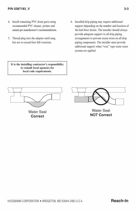
• When connecting drip piping, the water seal must be used as part of the drip piping to prevent air leakage or insect entrance. Never use two water seals in series in any one drip pipe. Double water seals in series will cause an air lock anD prevent Draining.
• Pitch the drip piping in the direction of flow. There should be a minimum pitch of 1/4 in. per ft (20 mm per 1 m).
• Avoid long runs of drip piping. Long runs make it impossible to provide the pitch necessary for good drainage.
• Provide a suitable air break between flood rim of the floor drain and outlet of drip pipe. To meet code on low base merchan-disers, it may be necessary to install a field-supplied drip pipe reducer. An alternative is to cut the last section of drip pipe at an angle.
• Prevent drip pipes from freezing sweating or freezing:
A. Do NOT install drip pipes in contact with uninsulated suction lines. Suction lines should be insulated with a non-absorbent insulation material.
B. Where drip pipes are located in dead air spac-es, such as between merchandisers or between a merchandiser and a store wall, provide means to prevent drip pipe from sweating. External ventilation fans may be required to pre-vent sweating.
DRIP PIPING AND SPLASHGUARDS
Splashguard brackets MUST be installed before piping merchandiser.
(See Page 1-3)

3-2 Drip piping anD SplaShguarDS
P/N 0387183_V U.S. & Canada 1-800-922-1919 • Mexico 1-800-890-2900 • WWW.HUSSMANN.COM
1. Tee is factory-installed. Do not overtighten threads, or the drain fitting or tee may become damaged.
2. Do NOT use thread sealer on ABS drain fitting. If sealer is used the ABS drain fitting may crack or leak! (If a tee needs to be installed it should be tightened no more than 4 turns.) Do not overtighten threads.
3. Dry fit the supplied water seal / trap to ensure approximately 1/2 in. of clearance from the bottom of the trap to the floor as shown.
NOTE: It may be necessary to rotate water seal (trap) inside the tee a few degrees to ensure clearance at two locations. There must be clearance 1) between the bottom of the water seal and the floor, and 2) between the top of the water seal outlet and the bottom of the merchandiser. Do not over-rotate or gravity seal may be compromised. Always rotate trap bottom toward merchandiser support rail.
1/2 in. Clearance to FloorApprox.
Factory-InstalledTee Fitting
Factory Installed (four turns)
Do NOT use Thread Sealer on Drain Fitting!
(Drain Fitting)
Rotate Water Seal towards back of Merchandiser if required
P/N 0387183_V 3-3
Reach-InHUSSMANN CORPORATION • BRIDGETON, MO 63044-2483 U.S.A.
4. Install remaining PVC drain parts using recommended PVC cleaner, primer and cement per manufacturer’s recommendations.
5. Thread plug into the adapter until snug but not to exceed four full rotations.
6. Installed drip piping may require additional support depending on the number and location of the hub floor drains. The installer should always provide adequate support to all drip piping arrangements to prevent excess stress on all drip piping components. The installer must provide additional support when “evac” type waste water systems are applied.
It is the installing contractor’s responsibility to consult local agencies for
local code requirements.
3-4 Drip piping anD SplaShguarDS
P/N 0387183_V U.S. & Canada 1-800-922-1919 • Mexico 1-800-890-2900 • WWW.HUSSMANN.COM
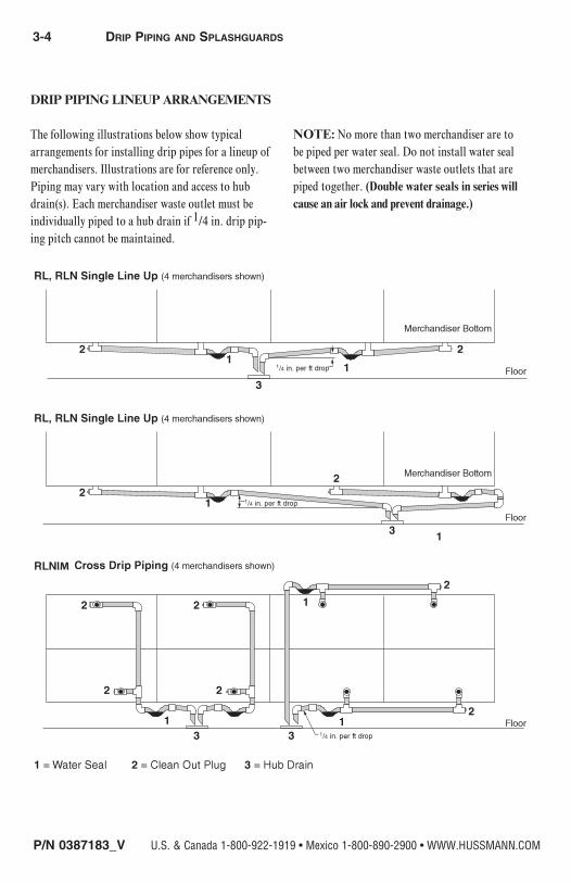
DRIP PIPING LINEUP ARRANGEMENTS
The following illustrations below show typical arrangements for installing drip pipes for a lineup of merchandisers. Illustrations are for reference only. Piping may vary with location and access to hub drain(s). Each merchandiser waste outlet must be individually piped to a hub drain if 1/4 in. drip pip-ing pitch cannot be maintained.
NOTE: No more than two merchandiser are to be piped per water seal. Do not install water seal between two merchandiser waste outlets that are piped together. (Double water seals in series will cause an air lock and prevent drainage.)
M
P/N 0387183_V 3-5
Reach-InHUSSMANN CORPORATION • BRIDGETON, MO 63044-2483 U.S.A.
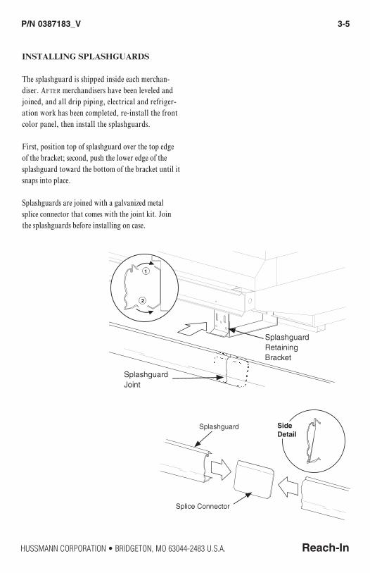
INSTALLING SPLASHGUARDS
The splashguard is shipped inside each merchan-diser. after merchandisers have been leveled and joined, and all drip piping, electrical and refriger-ation work has been completed, re-install the front color panel, then install the splashguards.
First, position top of splashguard over the top edge of the bracket; second, push the lower edge of the splashguard toward the bottom of the bracket until it snaps into place.
Splashguards are joined with a galvanized metal splice connector that comes with the joint kit. Join the splashguards before installing on case.

3-6 Drip piping anD SplaShguarDS
P/N 0387183_V U.S. & Canada 1-800-922-1919 • Mexico 1-800-890-2900 • WWW.HUSSMANN.COM
SEALING SPLASHGUARD TO FLOOR
If requIred by local sanitation codes, or if desired by the customer, plastic splashguards may be sealed to the floor using silicone type sealer. The amount needed will depend on how much the floor is out of level.
• Remove all dirt, wax and grease from the area of the splashguard where adhesion will be necessary. This is to ensure a good, secure installation.
• Apply a good silicone type sealer along the bottom of the splashguard. Sealant must be removed and replaced when servicing.
OptIOnal stainless steel splashguards may be sealed to the floor using a vinyl cove base trim. The size of trim needed will depend on how much the floor is out of level.
To install the trim to the splashguard:• Remove all dirt, wax and grease from the area of the splashguard where adhesion will be necessary. This is to ensure a good and secure installation.
• Apply a good contact cement to the cove trim and allow proper drying time according to the directions supplied with the cement.
• Install the trim to the splashguard so that it is lying flush with the floor. Do not seal the trim to the floor.
• If required by local health codes Cove Trim may be sealed to the floor using a silicone type sealer. Sealant must be removed and replaced when servicing.

P/N 0387183_V 4-1
Reach-InHUSSMANN CORPORATION • BRIDGETON, MO 63044-2483 U.S.A.
STARTUP AND OPERATION
See the merchandiser’s Technical Data Sheet for refrigerant settings and defrost require ments. Bring merchandisers down to the operating temperatures listed on the data sheet.
Excessive ambient conditions may cause con-densation and therefore sweating of doors. Facility operators should monitor doors and floor conditions to ensure safety of persons.
STOCKING
Product should NOT be placed in merchandisers until all refrigeration controls have been adjusted and merchandisers are at proper operating temperature.
All shelves and the lower deck are intended to display product. Shelf height is adjustable in one inch incre-ments. Spacing of 12 inches is recommended for most applications. Maximum load per shelf is 170 pounds. Merchandisers may be ordered with optional “L” shaped wire shelves.
Proper rotation of product during stocking is necessary to prevent product loss. Always bring the oldest product to the front and set the newest to the back.
Air dischArge And return flues must remAin open And free of obstruction At All times to provide proper refrigeration and air curtain performance. Do not allow product, packages, signs, etc. to block these grilles. Do not use non-approved shelving, baskets, display racks, or any accessory that could hamper air curtain performance.
Do not prop doors open while stocking. And keep the doors closed as much as possible to prevent coil frosting and high merchandiser temperature.
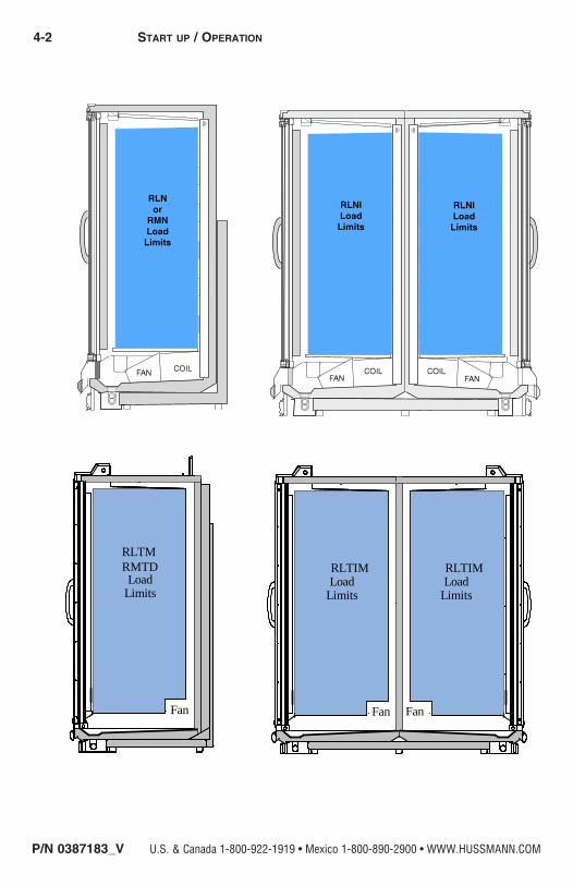
LOAD LIMITS
Shelf life of perishables will be short if load limit is violated. At no time should merchAndisers be stocked beyond the loAd limits indicAted.
Various shelf depths are offered with Reach In cases. The standard depth on all Reach-In cases is 22” (21” on RFLNS and RFMNS cases). Some cases have been designed to support larger shelves, but require design modifications to support the extra shelf length. These cases have a label near the serial plate that reads: This case has been reinforced to support 26” shelves.
DO NOT INSTALL 26” SHELVES IN ANY REACH IN CASE THAT DOES NOT HAVE THIS LABEL.
Do not block honeycomb.
START UP / OPERATION
Hussmann recommends solid shelves for ice cream.
Do not store items or flammable materials atop the unit. Do not walk on case.
4-2 Start up / OperatiOn
P/N 0387183_V U.S. & Canada 1-800-922-1919 • Mexico 1-800-890-2900 • WWW.HUSSMANN.COM
Fan
RLTMRMTDLoad
Limits
���
���
RLTIMLoad
Limits
RLTIMLoad
Limits
Fan Fan

P/N 0387183_V 4-3
Reach-InHUSSMANN CORPORATION • BRIDGETON, MO 63044-2483 U.S.A.
This is an NSF-7 &US FDA Food Code
RequiredThermometer
Hussmann P/N 0429971_C 10/2007
Hussmann Corporation • 12999 St. Charles Rock Road • Bridgeton, MO 63044-2483 U.S. & Canada 1-800-922-1919 • Mexico 1-800-890-2900E • www.hussmann.com
© 2007 Hussmann Corporation
Thermometer — Hussmann Part TM.4911251
INSTALLING FDA/NSF REQUIRED THERMOMETER
The following pages provide the same information that ships with the thermometer. This requirement does not apply to display refrigerators intended for bulk produce (refer to Page 1-1). Please note that the tape cannot be exposed after installation.

4-4 Start up / OperatiOn
P/N 0387183_V U.S. & Canada 1-800-922-1919 • Mexico 1-800-890-2900 • WWW.HUSSMANN.COM
Each installation will be different
depending on how the unit is
stocked, shopping patterns in the
department and ambient conditions
of the store. The suggested loca-
tions provided herein are possible
locations. It is the responsibility of
the purchaser / user to determine
the location within the food storage
area of the unit that best meets the
code requirements above.
The thermometer may need to be
moved several times to find the
warmest location. Mounting options
include flexible plastic for price tag
molding application, magnet
applied to back of flexible plastic for
steel end wall, and double stick
tape. Tape must not be exposed
after installation.
Questions about either code should
be addressed to local agencies or
other appropriate officials.
Important – Please read!
Keep with merchandiser
or give to store manager.
DO NOT DESTROY.
This thermometer is provided in response to United States
Food and Drug Administration (US FDA) Food Code [ http://www.fda.gov/ ]
and
National Sanitation Foundation (NSF / ANSI) Standard 7 [ http://www.nsf.org/ ]

P/N 0387183_V 5-1
Reach-InHUSSMANN CORPORATION • BRIDGETON, MO 63044-2483 U.S.A.
CARE AND CLEANING
Long life and satisfactory performance of any equipment is dependent upon the care it receives. To ensure long life, proper sanitation and minimum maintenance costs, these merchandisers should be thoroughly cleaned, all debris removed and the interiors washed down, weekly.
Fan PlenumTo facilitate cleaning, the fan plenum is hinged and also fastened with screws at each end. After cleaning be sure the plenum is properly lowered into position and that screws are reinstalled or product loss will result due to improper refrigeration.
Always*Clear™ GlassWipe inside of glass with isopropyl alcohol and a soft cloth. Allow surface to dry before closing door. Use of other cleaners or abrasives may damage the Always*Clear surface, and/or void the warranty. Refer to manual that ships with doors.
Interior SurfacesThe interior surfaces may be cleaned with most domestic detergents, ammonia based cleaners and sanitizing solutions with no harm to the surface.
Exterior SurfacesThe exterior surfaces should be cleaned with a mild detergent and warm water to protect and maintain their attractive finish. Never use abrasive cleaNsers or scouriNg pads.
Do Not Use:•Abrasive cleansers and scouring pads, as these will mar the finish.
• Coarse paper towels on coated glass.
•Ammonia-based cleaners on acrylic parts.
•Solvent, oil or acidic based cleaners on any interior surfaces.
MAINTENANCE
Do NOT use HOT water on COLD glass surfaces. This can cause the glass to shatter and could result in personal injury. Allow glass fronts,
ends and service doors to warm before applying hot water.
SHUT FANS OFF DURING CLEANING PROCESS.
5-2 Maintenance
P/N 0387183_V U.S. & Canada 1-800-922-1919 • Mexico 1-800-890-2900 • WWW.HUSSMANN.COM
do use:• Remove the product and all loose debris to avoid
clogging the waste outlet.
• Store product in a refrigerated area such as a freezer. Remove only as much product as can be taken to the freezer in a timely manner.
• First turn off refrigeration, then disconnect electrical power.
• Thoroughly clean all surfaces with soap and hot water. Do not use steam or high water pressure hoses to wash the interior. these will destroy the merchaNdisers’ sealiNg causiNg leaks aNd poor performaNce.
• Remove screws and lift hinged fan plenum for cleaning. be sure to repositioN the faN pleNum after cleaNiNg merchaNdiser.
• Take care to minimize direct contact between fan motors and cleaning or rinse water.
• Rinse with hot water, but do NOT flood. never introDuce water faster than the waste outlet can remove it.
• Allow merchandisers to dry before resuming operation.
• After cleaning is completed, turn on power and refrigerant to the merchandiser.
• Verify that merchandiser is working properly.
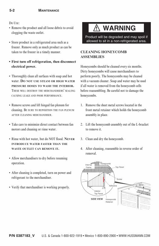
CLEANING HONEYCOMB ASSEMBLIES
Honeycombs should be cleaned every six months. Dirty honeycombs will cause merchandisers to perform poorly. The honeycombs may be cleaned with a vacuum cleaner. Soap and water may be used if all water is removed from the honeycomb cells before reassembling. Be careful not to damage the honeycombs.
1. Remove the sheet metal screws located in the front metal retainer which holds the honey comb assembly in place.
2. Lift the honeycomb assembly out of the L-bracket to remove it.
3. Clean and dry the honeycomb.
4. After cleaning, reassemble in reverse order of removal.
Product will be degraded and may spoil if allowed to sit in a non-refrigerated area.

P/N 0387183_V 5-3
Reach-InHUSSMANN CORPORATION • BRIDGETON, MO 63044-2483 U.S.A.
CLEANING STAINLESS STEEL SURFACES
Use non-abrasive cleaning materials, and always polish with grain of the steel. Use warm water or add a mild detergent to the water and apply with a cloth. Always wipe rails dry after wetting.
Use alkaline chlorinated or non-chlorine containing cleaners such as window cleaners and mild detergents. Do not use cleaners containing salts as this may cause pitting and rusting of the stainless steel finish. Do not use bleach.
Clean frequently to avoid build-up of hard, stubborn stains. A stainless steel cleaning solution may be used periodically to minimize scratching and remove stains. Rinse and wipe dry immediately after cleaning. Never use hydrochloric acid (muriatic acid) on stainless steel.
CLEANING COILS
NEVER USE SHARP OBJECTS AROUND COILS. Use a soft brush or vacuum brush to clean debris from coils.
Do not puncture coils!
Do not bend fins. Contact an authorized service technician if a coil is punctured, cracked, or otherwise damaged.
Do NOT use chlorine or ammonia-based cleaners to clean aluminum coils.
ICE in or on the coil indicates the refrigeration and defrost cycle is not operating properly. Contact an authorized service technician to determine the cause of icing, and to make adjustments as necessary. To maintain product integrity, move all product to a cooler until the unit has returned to normal operating temperatures.
CLEANING UNDER MERCHANDISERS
Remove splashguards not sealed to floor. Use a vacuum with a long wand attachment to remove accumulated dust and debris from under the merchandiser.
REMOVING SCRATCHES FROM BUMPERMost scratches and dings can be removed using the following procedure.
1. Use steel wool to smooth out the surface area of the bumper or top rail.
2. Clean area.
3. Apply vinyl or car wax and polish surface for a smooth glossy finish.
Do NOT allow cleaning agent or cloth to contact food product.

5-4 Maintenance
P/N 0387183_V U.S. & Canada 1-800-922-1919 • Mexico 1-800-890-2900 • WWW.HUSSMANN.COM
NOTES:

P/N 0387183_V 6-1
Reach-InHUSSMANN CORPORATION • BRIDGETON, MO 63044-2483 U.S.A.
REPLACING FAN MOTORS AND BLADES
See cross section for location of evaporator fans. Should it ever be necessary to service or replace the fan motors or blades be certain that the fan blades are re-installed correctly.
For access to RL / RM / RLN / RMN / RLNI / RLNIE fans:
1. Turn off power.
2. Remove bottom display pans.
3. Disconnect fan from wiring harness.
4. Remove fan blade.
5. Remove screws holding fan motor/bracket assembly to plenum and remove assembly.
6. Replace fan motor/bracket assembly and reinstall screws.
7. Reinstall fan blade.
8. Reconnect fan to wiring harness.
9. Turn on power.
10. Verify that motor is working and blade is turning in the correct direction.
11. Close large air gaps under fan plenum. Warmer air moving into refrigerated air reduces effective cooling. If the plenum does not rest against the case bottom without gaps, apply foam tape to the bottom of the fan plenum to reduce improper air movement, however defrost water should not be blocked by fan plenum. Do NOT seal fan plenum so that water can not drain.
12. Replace display pans. Bring merchandiser to operating temperature before restocking.
SERVICE
Hussmann recommends against frame heater cycling with Innovator doors to prevent door seals from freezing to the frames and tearing.
Always disconnect the electrical power at the main disconnect when servicing or replacing any electrical component. This includes, but is not limited to, such items as fans, heaters, thermostats and lights.
S ervi c e # MO.XX X XX X X
XXXXXXX
Fan Assembly
Speed-Nut
Fan BladeScrews
Motor
AirflowDirection
Bracket
Plenum
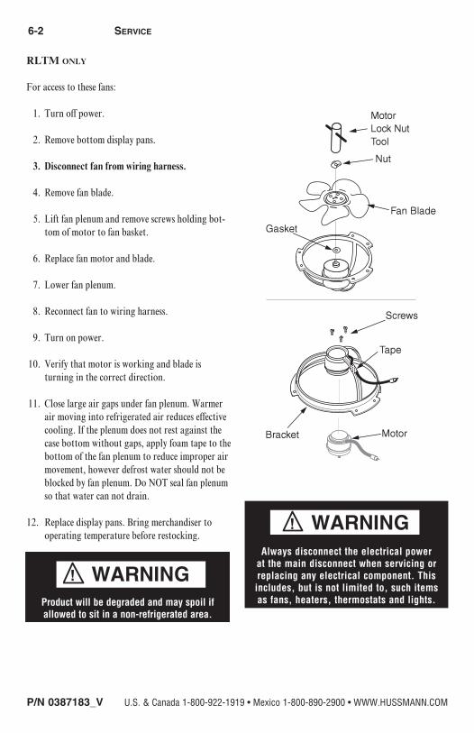
6-2 Service
P/N 0387183_V U.S. & Canada 1-800-922-1919 • Mexico 1-800-890-2900 • WWW.HUSSMANN.COM
RLTM only
For access to these fans:
1. Turn off power.
2. Remove bottom display pans.
3. Disconnect fan from wiring harness.
4. Remove fan blade.
5. Lift fan plenum and remove screws holding bot-tom of motor to fan basket.
6. Replace fan motor and blade.
7. Lower fan plenum.
8. Reconnect fan to wiring harness.
9. Turn on power.
10. Verify that motor is working and blade is turning in the correct direction.
11. Close large air gaps under fan plenum. Warmer air moving into refrigerated air reduces effective cooling. If the plenum does not rest against the case bottom without gaps, apply foam tape to the bottom of the fan plenum to reduce improper air movement, however defrost water should not be blocked by fan plenum. Do NOT seal fan plenum so that water can not drain.
12. Replace display pans. Bring merchandiser to operating temperature before restocking.
Always disconnect the electrical power at the main disconnect when servicing or replacing any electrical component. This includes, but is not limited to, such items as fans, heaters, thermostats and lights.Product will be degraded and may spoil if
allowed to sit in a non-refrigerated area.

P/N 0387183_V 6-3
Reach-InHUSSMANN CORPORATION • BRIDGETON, MO 63044-2483 U.S.A.
REPLACING ELECTRIC DEFROST HEATERS FOR (RL / RLN / RLNI / RLNIE) ONLY
Electric defrost requires a heater on the front and rear of the coil as shown. The heaters are held in place by tabs in the coil brackets.
Front Defrost Heater
1. Disconnect Power.
2. Lift fan plenum up and back to access the heater.
3. Bend tabs holding heater to horizontal.
4. Remove heater from coil bracket.
5. Position new heater in bracket.
6. Bend tabs back to vertical to hold heater in bracket.
7. Replace the coil cover and lower fan plenum.
8. Turn on power.
9. Verify that heater is working correctly.
10. Close air gaps under fan plenum. Warmer air moving into refrigerated air reduces effective cooling. If the plenum does not rest against the case bottom without gaps, apply foam tape to the bottom of the fan plenum to reduce improper air movement. Use silicone sealant to close other gaps.
11. Replace display pans. Bring merchandiser to operating temperature before restocking.
Rear Defrost Heater
1. Disconnect Power.
2. Remove coil cover.
3. Remove clips holding heater to coil tube.
4. Remove heater from slots in coil bracket.
5. Position new heater in slots.
6. Replace clips.
7. Replace the coil cover.
8. Turn on power.
9. Verify that heater is working correctly.
10. Replace display pans. Bring merchandiser to operating temperature before restocking.
Electric Defrost

6-4 Service
P/N 0387183_V U.S. & Canada 1-800-922-1919 • Mexico 1-800-890-2900 • WWW.HUSSMANN.COM
REPLACING Electric Defrost Heaters (RLTM Only)
RLTM electric defrost heaters are located in front of and behind the coil. Mounting brackets and supports are attached to plenum brackets.
1. Disconnect Power.
2. Remove display pans.
3. Remove coil mounting screws and slide coil towards the front of the case.
4. Bend tabs holding heater to horizontal.
5. Remove heater from coil brackets.
6. Position new heater in brackets.
7. Bend tabs back to vertical to hold heater in bracket.
8. Push back in alignment with plenum baffles and reinsert coil mounting screws.
9. Turn on power.
10. Verify that heater is working correctly.
11. Close air gaps between the coil covers and the plenum baffles with silicone sealant.
12. Replace display pans. Bring merchandiser to operating temperature before restocking.
HUSS
MAN
N_GD
F_2.
1 SH
EET
SIZE
D
THIRD ANGLE
PROJECTION
UNLESS OTHERWISE SPECIFIED DIMENSIONS ARE IN INCHES.SHEET 1 OF 2
RLTM300 A
REACH-IN I/C-FF 3DRT
MATERIAL- MODEL BY / DWG BY- MLYONS / DWGby
ECN-712486REF- RLT300
Coil Mounting Screw
Coil Mounting Screw
Defrost Heater
HUSS
MAN
N_GD
F_2.
1 SH
EET
SIZE
D
THIRD ANGLE
PROJECTION
UNLESS OTHERWISE SPECIFIED DIMENSIONS ARE IN INCHES.SHEET 1 OF 2
RLTM300 A
REACH-IN I/C-FF 3DRT
MATERIAL- MODEL BY / DWG BY- MLYONS / DWGby
ECN-712486REF- RLT300
Coil Mounting Screw
Coil Mounting Screw
Defrost Heater
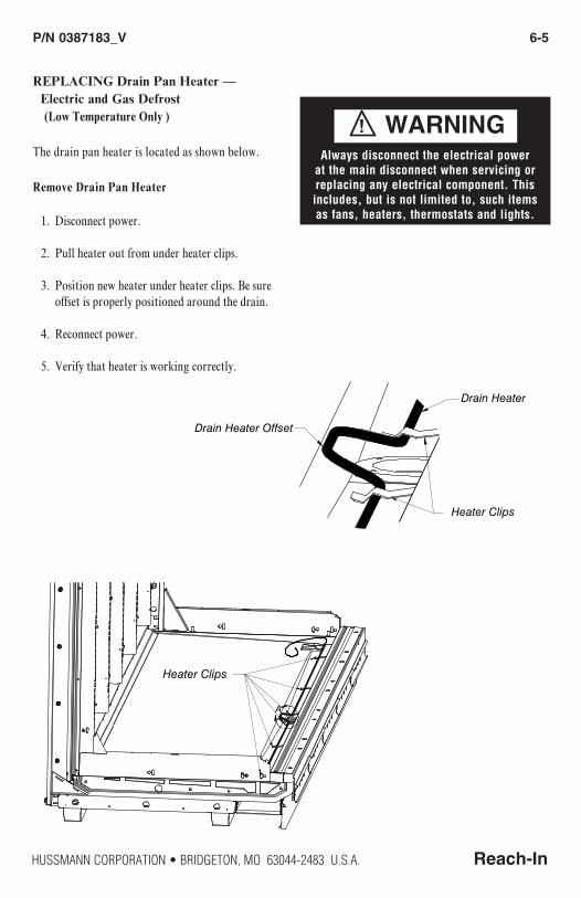
P/N 0387183_V 6-5
Reach-InHUSSMANN CORPORATION • BRIDGETON, MO 63044-2483 U.S.A.
REPLACING Drain Pan Heater — Electric and Gas Defrost (Low Temperature Only )
The drain pan heater is located as shown below.
Remove Drain Pan Heater
1. Disconnect power.
2. Pull heater out from under heater clips.
3. Position new heater under heater clips. Be sure offset is properly positioned around the drain.
4. Reconnect power.
5. Verify that heater is working correctly.
Always disconnect the electrical power at the main disconnect when servicing or replacing any electrical component. This includes, but is not limited to, such items as fans, heaters, thermostats and lights.
rro: No refe Errenrocr:e N
A
DETAIL A
Drain Heater Offset
Drain Heater
Heater Clips
Heater Clips
rro: No refe Errenrocr:e N
A
DETAIL A
Drain Heater Offset
Drain Heater
Heater Clips
Heater Clips

6-6 Service
P/N 0387183_V U.S. & Canada 1-800-922-1919 • Mexico 1-800-890-2900 • WWW.HUSSMANN.COM
SERVICING VERTICAL LIGHTING
Refer to door manufacturer’s manual for servicing of vertical lamps.
SERVICING DOORS AND FRAMES
See door manufacturer’s service manual for servicing information. One manual is shipped with each merchandiser.
Hussmann’s Innovator Door manual (P/N 0425683) can be found on the website www.hussmann.com.
REPLACING DOOR OR DOOR FRAME PARTS
Parts for Reach-in doors and door frame assemblies must be ordered direct from the door manufacturer This includes the glass doors, door frame assemblies, lamps, ballasts, door handles, hold open slides, and power cords.
Refer to specific warranty supplied with the door. The manufacturers have a warranty against moisture penetration, a warranty against tempered glass breakage, and a warranty on ballasts. Lamps are not covered by Hussmann or the door manufacturer.
REPLACING DAMAGED DRAIN FITTING
The following procedure is for the field repair of a broken drain fitting.
1. Use a drill with a 1 7/8-inch (48 mm) hole saw to drill out the bottom of the drain fitting. Be sure to drill completely through fitting and bottom liner.
2. Insert adapter into drain fitting. Do NOT use thread sealer on ABS drain fitting. If sealer is used the ABS drain fitting may crack or leak! (Tee should be tightened no more than 4 turns.) Do not overtighten threads.
Drain FittingViewed from Inside Merchandiser
Drain Fitting Viewed from Inside Case
Do NOT use Thread Sealer on Drain Fitting!
End Section View

P/N 0387183_V 6-7
Reach-InHUSSMANN CORPORATION • BRIDGETON, MO 63044-2483 U.S.A.
REPAIRING ALUMINUM COIL
The aluminum coils used in Hussmann merchandisers may be easily repaired in the field. Materials are available from local refrigeration wholesalers.
Hussmann recommends the following solders and technique:
Solders
Aladdin Welding Products Inc. P.O. Box 7188 1300 Burton St. Grand Rapids, MI 49507 Phone: 1-800-645-3413 Fax: 1-800-645-3414
X-Ergon 1570 E. Northgate P.O. Box 2102 Irving, TX 75062 Phone: 1-800-527-9916
NOTE: Hussmann Aluminum melts at 1125°F (607°C)
Aladdin 3-in-1 rod at 732°F (389°C)
X-Ergon Acid core at 455°F (235°C)
Technique:
1. Locate Leak.
2. REMOVE ALL PRESSURE.
3. Brush area UNDER HEAT.
4. Use PRESTOLITE TORCH ONLY. Number 6 tip.
5. Maintain separate set of stainless steel brushes and USE ONLY ON ALUMINUM.
6. Tin surface around area.
7. Brush tinned surface UNDER HEAT, thoroughly filling the open pores around leak.
8. Repair leak. Let aluminum melt solder, NOT the torch.
9. Don’t repair for looks. Go for thickness.
10. Perform a leak check.
11. Wash with water.
12. Cover with a good flexible sealant.

To obtain warranty information or other support, contact your
Hussmann representative. Please include the model and serial number of the product.
Hussmann Corporation, Corporate Headquarters: Bridgeton, Missouri, U.S.A. 63044-2483 01 October 2012
Recommended