Loughborough UniversityInstitutional Repository
A new methodology forrequirements elicitation
This item was submitted to Loughborough University's Institutional Repositoryby the/an author.
Additional Information:
• A Doctoral Thesis. Submitted in partial fulfilment of the requirementsfor the award of Doctor of Philosophy of Loughborough University.
Metadata Record: https://dspace.lboro.ac.uk/2134/12637
Publisher: c© Al-Zaid
Please cite the published version.

This item was submitted to Loughborough University as a PhD thesis by the author and is made available in the Institutional Repository
(https://dspace.lboro.ac.uk/) under the following Creative Commons Licence conditions.
For the full text of this licence, please go to: http://creativecommons.org/licenses/by-nc-nd/2.5/

Pilkington Library
•• Lo~ghb.orough ., Umverslty
AuthorlFiling Title .... ~.\.::.~.~ .. I.l> ........................ .
Vol. No. ............ Class Mark ..... ! .................... .
Please note that fines are charged on ALL overdue items.
1~~I[llli1~ifIilllllllllllllllllllll

j
j
j
j
j
j
j
j
j
j
j
j
I
r j
r j
r j
r j
r j
r j
r j
r j
r j
r j
I

A New Methodology for Requirements Elicitation
By
Asad Saud AI-Zaid
A Doctoral Thesis
Submitted in partial fulfilment of the requirements for the award of doctor of philosophy of Loughborough University
June, 1999
Supervisor: Ray Dawson
Department' of Computer SCience
© AI-Zaid 1999

CIIIll$
Ace No.

Dedication
To my Wife, Children and my Brother Mohammed

Acknowledgments
"In The Name of Allah, The Most Benevolent, The Most Merciful"
I wish to express my gratitude to my supervisor Mr. Ray Dawson, for his guidance and
his continuous encouragement through out this research project. I am also very grateful to
Dr. Ian Newman, my director of research, for his support and advise especially at the
beginning of this research.
My sincere thanks also go to Dr. A. Blyth for his support and assistant in this research
project.
I wish to express my gratitude to the Bank of Bahrain and Kuwait for allowing me to
apply and test my new methodology on their work. I also would like to thank the
members of the project group for their support and assistants through out the case study.
I also wish to extend my gratitude to the Public Authority of Applied Education for
granted me the study and their financial support to complete this work.
Many thanks to fellow colleagues AbdulAziz Alkandari, AbdulAziz AI-Romi, Ahmad
AI-Sharah and Ghanima AI-Othman for their moral support and kindness. I also would
like to give a special thanks to Dr. Ismail Farhan for his constant support and
encouragement throughout this work.
Finally, I would like to express my gratefulness to my mother, wife, and children for their
prayers, love, courage, support and understanding during the long period of my absence.
III

Abstract
A survey of the literature has suggested that most of IT system failure in information
system development is due to problems of identifying and meeting users'
requirements. Conventional systems that support the waterfaII approach try to focus
on defining information processing requirements rather than looking at IT from a
wider perspective. This approach complicates the relationship between the client who
'owns' the problem and the developer who seeks to solve it. Therefore it is common
for systems to be created which do not satisfy the needs of their human operators even
though they are technicaIIy sound. The main aim of the research is to develop a new
methodology that can contribute to the effective determination of user requirement.
The new methodology has been constructed from unifying ORDIT (Organisational
Requirement Definition for Information Technology) and ISAC (Information System
Work and Analysis of Change) methodologies. Therefore it can solve a certain set of
problems, some which are solved by ORDIT, some which are also solved by ISAC
and some which neither of the two methodologies can solve. The activity model used
in ISAC is insufficient for solving the organisational issues, therefore it is replaced
with the responsibility model which is taken from ORDIT. The responsibility model
is used in order to give a clearer understanding of the organisation's structure, aim,
objectives and policies. The tables and tools, which are used in the change analysis
stage ofISAC, will be used in the new methodology for the purpose of identifying the
business problem, user objectives and change needs. These tools and models are used
in order to elicit requirements for different problem owner in different levels of the
organisation. The new methodology has been applied to a real case study in order to
demonstrate and evaluate its performance and usefulness. This case study showed the
new methodology to be useful and effective.
IV

Dedication
Declaration
Acknowledgments
Abstract
List of Contents
List of Figures
List of Tables
List of Abbreviation
List of Contents
ii
11l
IV
V
XIV
XVI
XV1l1
Chapter 1 Introduction .........•..........••...••...•........•.•.•.......................•........................ 1
1.0 The Research Problem ........................................................................................... I
1.1 Research Aims and Objectives ................................................................................ I
1.2 Research Hypothesis .............................................................................................. 2
1.3 Research Justification ............................................................................................ 3
1.4 Structure of the Thesis ........................................................................................... 4
Chapter 2 Background and Literature SuM·ey .......................................................... 7
2.0 Introduction ........................................................................................................... 7
2.1 Enterprise Modelling .............................................................................................. 7
2.1.1 Development of Enterprise Modelling ......................................................................... 8
2.1.2 Uses of Enterprise Modelling ...................................................................................... 9
2.1.3 Enterprise Modelling Objectives ................................................................................ 11
2.2 Software Engineering ........................................................................................... 12
2.2.1 TIle Uncertainty of Requirements .............................................................................. 14
2.2.2 Conflicts ................................................................................................................... 14
2.2.3 Altematives .............................................................................................................. 15
2.3 Organisational Requirement Engineering Techniques .................................. 15
2.3.1 Classification of Requirements Engineering................................................ 15
V

2.3.1.1 ANSA .......................................................................................................... 16
2.3.1.2 Axiological Framework ................................................................................ 17
. 2.4 Revie~ of Requirement Engineering Methods ...................................................... 18"\
2.5111e Soft System Thinking ............................................................................. 18 . . 2.5.1 The Soft Systems Method ......................................................................................... 18
. -2.5.2 The Structured System Analysis and Design Method (SSADM) ........................... 20
2.6111e Hard System Methods ............................... ,,,,,,,,, ................................. ...23 2.6.1 The Structured Analysis and Design Technique (SADT) Method ............................... 23
2.6.2 The Controlled Requirement Expression (CORE) Method ......................................... 26
2.6.3 Jackson Structured Development. ........ ,' .................................................................... 28
2.6.4 Hierarchical Development Methodology (HDM) ....................................................... 30
2.6.5 111e Fonnal Requirements Specification Teclmiques (FOREST) Method ................... 31
2.6.6 Role, Function and Action Nets Method .................................................................... 33
2.6.7 The Systematic Activity Modelling Method (SAMM) ............................................... 3~
2. 7111e Object Oriented Methods ......... '" ............................................................. 36 2.7.1 Object Oriented Analysis (AOO) Method ......... " .......................................... 36
2.8 The Scandinavian Style Method ...................................................................... 38
2.8.1 ISAC ............................................................................................... 38
2.9 111e Socio-technical System ............................................................................ 38
2.9.1 ETHICS ............................................................................................ 3 8
2.9.2 ORD IT .................................................................................................................... -l0
2.10 Discussion of the Five Groups of Methods in General ........................................ 42
2.11 Requirement Specification Languages ................................................................ 44
2.12 Specification as a Communication Medium ........................................................ 45
2.13 Justification for Choosing ISAC and ORDIT Methodology .......................... 47
2.14 Concluding Remarks .......................................................................................... 48
Chapter 3 ORDIT Methodology .. , .. , ............................................................... ..... 50
3.0 Introduction ......................................................................................................... 50
3.1 Component of the ORDIT Methodology .............................................................. 50
3.1.1 Scoping ................................................................................................................... 51
3.1.2 System Models ......................................................................................................... 51
3.1.3 Requirement Generation ........................................................................................... 52
Vt

3.1.4 Solution Options ....................................................................................................... 52
3.2 Tools Used in ORDIT Methodology .................................................................... 53
3.2.1 Responsibility Modelling .......................................................................................... 54
3.2.2 Obligation Model ...................................................................................................... 55
3.2.3 Activity Model .......................................................................................................... 55
3.2.4 Conversation Model .................................................................................................. 56 •
3.2.5 The ORDITEnterprise modelling .............................................................................. 56
3.3 The Concept of Role ............................................................................................ 60
3.4 The Concept of Structural and Contractual Role ................................................... 61
3.5 The concept of agency ......................................................................................... 65
3.6 Concluding Remarks ............................................................................................ 65
Chapter 4 Applying the University Library Case Study to ORDIT. ......................... 67
4.0 Introduction ......................................................................................................... 67
4.1 The University Library Case Study ...................................................................... 67
4.2 Applying the Library Case Study to ORDIT Methodology ................................... 70
U.l Scoping.............................. ... ... ........ ....... . . ..... 70
4.2.1.1 Decide on Perspectives to be Modelled ........................................................ 70
4.2.1.2 Define System Boundaries for the Chosen Prospective. and
Identify Responsibility Relationships within this Boundary .......................... 71
U.2 Modelling Stage ........................................................................................... 73
4.2.2.1 Define the top-level Responsibilities within !he System Boundary ................. 73
4.2.2.2 Create Conversation Diagram ....................................................................... 75
4.2.2.3 Construct an Abstract Model Showing the Pool of Responsibilities and
Obligations within the System as a Whole ..................................................... 76
4.2.2.4. Abstract Agency Model. .............................................................................. 79
4.2.3. Requirement Generation .......................................................................................... 81
4.2.3.1. Produce a model of !he existing system showing its structure ........................ 81
4.2.3.2 Construct a Role Relationship Diagram of the Existing System ..................... 83
4.2.4 Solution Capture ............................................................................................ 87
4.2.4.1 Draw Role Relationships Diagram of the Proposed System ......................... 87
vii

4.3 Strength of ORDIT Methodology ......................................................................... 90
4.4 Weaknesses ofORDIT Methodology ................................................................... 91
4.5 Concluding Remarks ............................................................................................ 92
Chapter 5lSAC Methodology ................................................................................. 93
5.0 Introduction ......................................................................................................... 93
5.1 ISAC Methodology ............................................................................... : .............. 93
5.2 Change Analysis .................................................................................................. 94
5.2.1 List of Problems ........................................................................................................ 95
5.2.2 Analyse the Problems ................................................................................................ 95
5.2.3 Making Activity Model ofllle Current Business ........................................................ 96
5.2.4 Analyse Goals ........................................................................................................... 96
5.2.5 Define Change Needs ................................................................................................ 97
5.2.6 Generate Change Alternatives ................................................................................... 97
5.2.7 Make Activity Model of Desired Situations ............................................................... 97
5.2.8 Evaluate Alternatives ................................................................................................ 98
5.2.9 Choose an Alternative ............................................................................................... 98
5.3 Activity Study ...................................................................................................... 98
5.3.1 Decomposition into Information Subsystem ............................................................... 99
5.3.2 Analysis of Information Subsystems .......................................................................... 99
5.3.3 Co-ordination of Information Subsystems ................................................................ 100
5.4 Information Analysis ......................................................................................... 100
5.4.1 Precedence and Component Analysis ..... : ................................................................ 101
5.4.2 Process Analysis ..................................................................................................... 102
5.4.3 Property Analysis .................................................................................................... 102
5.5 Data System Design (OSO) ................................................................................ 102
5.6 Equipment Adaptation ....................................................................................... 104
5.6.1 Equipment Study ..................................................................................................... 104
5.6.2 Adaptation of Computer-Based Routines ................................................................. 105
5.7 Tools Used in ISAC Methodology ..................................................................... 105
5.7.1 A-graph ................................................................................................................. 105
5.7.2 I-graph ................................................................................................................. 105
Vlll

5.7.3 C-graph ................................................................................................................. 106
5.8 Concluding Remarks................................... ....................................................... 106
Chapter 6 Applying the University Library Case Study to [SAC ........................... 107
6.0 Introduction ....................................................................................................... 107
6.1 Change Analysis ................................................................................................ 107
6.1.1 List of Problems .................................................................................................. : ... 107
6.1.2 List of Problem Owners .......................................................................................... 108
6.1.3 Analyses of Interest Group ...................................................................................... 109
6.1.3.1 Property Table .......................................................................................... 112
6.1.4 Description of Current Activities ............................................................................. 113
6.1.5 Description of Objectives ........................................................................................ 122
6.1.6 Evaluation of Current Situation and Analysis of Needs for Changes ......................... 122
6.1. 7 Study of change Alternatives .................................................................................. 123
6.1.8 Make Activity Model of Desired Situations ............................................................ IH
6.1.9 Evaluate Alternatives ............................................................................................. 129
6.1.10 Choose an Alternative ........................................................................................... 130
6.2 Activity Studies ................................................................................................. 131
6.3 Information System ............................................................................................ 145
6.4 Weaknesses and Limitation ofISAC Methodology ............................................. 160
6.5 Strength OfISAC Methodology ......................................................................... 162
6.6 Concluding Remarks .......................................................................................... 163
Chapter 7 A Critical El'Qluation of [SAC and ORD1T Methodologies ....•.......• 164
7.0 Introduction ....................................................................................................... 164
7.1 Rational for Choosing Factors for the New Methodology ............................. 164
7.2 The four Essential Factors for the New Methodology ......................................... 167
7.2.1 User Needs ............................................................................................................ 167
7.2.2 Organisational Needs .............................................................................................. 167
7.2.3 Business Needs ....................................................................................................... 167
7.2.4 Socio-technical Needs ............................................................................................. 168
IX

7.3 The Evaluation Criteria ...................................................................................... 168
7.3.1 Stakeholders' Information ........................................................................................ 168
7.3.2 Attitnde to IT .......................................................................................................... 169
7.3.3 User job needs ........................................................................................................ 170
7.3.4 Current Work Pattern .............................................................................................. 171
7.3.5 Infrastructure Support for IT ................................................................................... 173
7.3.6 Problem Identification ............................................................................................. 173
7.3.7 Pre-implementation Impact Analysis ...................................................................... 175
7.3.8 Organizational Issues Analysis ................................................................................ 175
7.3.9 Business strategy and objectives: ............................................................................. 177
7.3.10 IT Strategy ........................................................................................................... 178
7.3.11 Business Mission ................................................................................................. 178
7.3.12 Conventional Technical Needs Analysis ............................................................... 179
7.3.13 Socio-Technical Needs ........................................................................ 179
7.4 Evaluation Criteria framework ........................................................................... 180
7.5 ISAC Limitations and Strengths of the Four Factors .......................................... 181
7.6 ORDIT Limitations and Strengths of the Four Factors ...................................... 182
7.7 Why Use the Responsibility Model ................................................................... 183
7.8 Concluding Remarks .......................................................................................... 184
Chapter 8 The New MetllOtlology ....... _ ............... _ ..............................•................... 185
8.0 Introduction ....................................................................................................... 185
8.1 The New Methodology ..................................................................... 186
8.2 Change Analysis ................................................................................................ 187
8.2.1 Identify the Project Plan ........................................................................................ 187
8.2.1.1 Identify the business mission and problems with current systems through
an initial meeting with sponsor .................................................................... 188
8.2.1.2 Issue a list of problems identified ................................................................. 188
8.2.1.3 List groups of people or agencies that are affected by the problems
identified .................................................................................................... 189
8.2.1.4 Develop a matrix of the problems to be solved VS problem owners .............. 189
x

8.2.2 Make a quantitative study for Each problem identified ............................................ 190
8.2.2.1 Perform a cause-effect amlysis for each problem ......................................... 190
8.2.2.2 Conduct a session with problem owners to discuss and approve
updated problems ........................................................................................ 192
8.2.2.3 Produce a matrix of the updated problems VS problem owners ..................... 192
8.2.2.4 Issue a matrix of problems quantified ........................................................... 193
8.2.3 Model the current system using the responsibility mode!.. ........................................ 194
8.2.3.1 Identify the boundaries of the current system ................................................ 194
8.2.3.2 Identify responsibilities, obligations and activities for each
department involved .................................................................................... 194
8.2.3.3 Model the current system using the responsibility ......................................... 195
8.2,4 Identify new system goal (change needs) and requirements ..................................... 195
8.2.4.1 Conduct a session with problem owners to discuss the new goals ................. 195
8.2.4.2 List the new system goals ............................................................................ 196
8.2.4.3 For each goal find-out the problems tI13t prevent it from being achieved ...... 197
8.2.4.4 Cluster problems into groups of similar problems that are
related to the same goals ............................................................................. 197
8.2.4.5 Issue a matrix of problems against goals (Cll3Dge needs) .............................. 197
8.2.5 Generate a list of change alternative ........................................................................ 197
8.2.5.1 Meet witIl problem owners ........................................................................... 197
8.2.5.2 Evaluate change needs according to problem owners point view ................... 198
8.2.5.3 Issue a matrix of change altermtives ............................................................ 198
8.3 System Modelling .............................................................................................. 199
8.3.1 Choose the best aItermtive package for tIle organisation .......................................... 199
8.3.1.1 Present altermtive packages of related cll3Dges to be investigated ................ 199
8.3.1.2 Evaluate each package solution .................................................................... 199
8.3.1.3 Select tIle best package ................................................................................ 199
8.3.1.4 Pre-implementation impact analysis ............................................................. 200
8.3.2 Model tIle required system using the responsibility mode!.. ...................................... 200
8.3.2.1 Decompose the responsibility model in the change amlysis stage
into obligations using the role model. .......................................................... 200
8.3.2.2 Discuss the new assignment pf resp04sibilities resulting from
the proposed system .................................................................................... 200
8.4 Socio-Technical Design ..................................................................................... 201
8.4.1 Define IT Infrastructure ......................................................................................... 20 I
Xl

8.4.2 Define IT Strategy .................................................................................................. 20 1
8.4.3 Define the system structure (object, attributes, Methods, Validation) ....................... 202
8.4.4 Development ............................................................................. " ........................... 202
8.4.4.1 Software Coding .......................................................................................... 202
8.4.4.2 Quality Assurance ............................................... """""'''''''''''''''''''''' ........ 202
8.5 Implementation ......................................................... """ .. "" ............................. 203
8.5.1 Provide end user training ......................................................................................... 203
8.5.2 First Parallel Run .................................................................................................... 203
8.5.3 Second Parallel ....................................................................................................... 203
8.5.4 Technical Training ................................. " ............................................................... 204
8.5.5 Documentation ....................................................................................................... 204
8.6 Concluding Remarks .......................................................................................... 204
Chapter 9 Applying the Bank Case Study to the New Methodology ...................... 206
9.0 Introduction ....................................................................................................... 206
9.1 Change Analysis ................................................................................................ 209
9. 1. 1 Identify the Project Plan .......................................................................................... 209
9.1. 1.1 Identify the business mission and
problems with current systems by meeting with sponsor ......................... 209
9 .1.l.2 Issue a list of problems identified ................................................................. 209
9.1. 1.3 List groups of people or agencies that are affected by the problems identified 211
9.1. 1..1 Develop a matrix of the problems to be solved VS problem owners .............. 211
9.1.2 Make a Quantitative Study for Each Problem Identified ........................................... 213
9.1.2.1 Perfonn a cause-effect analysis for each problem ......................................... 213
9.1.2.2 Conduct a session with problem owners to discuss and approve updated
problems.lnconsistency of data .................................................................... 216
9.1.2.3 Produce a matrix of the updated problems VS problem owners .................... 217
9.1.2.4 Issue a matrix of problems quantified ........................................................... 218
9.1.3 Model the Current System Using the Responsibility ModeL .................................... 2 19
9.1.3.1 Identify the boundaries of the current system ................................................ 2 1 9
9.1.3.2 Identify responsibilities, obligations and activities
for each department involved ..................................................................... 220
9.1.3.3 Model the current system using the responsibility model .............................. 227
9.1.4 Identify New System Goal (Change Needs) and Requirements ............................... 232
Xli

9.1.4.1 Conduct a session with problem owners to discuss the new goals ................. 232
9.1.4.2 List the new system goals ............................................................................ 233
9.1.4.3 For each goal find-out the problems that prevent it from being achieved ...... 234
9.1.4.4 Cluster problems into groups of similar problems that are
related to the same goals ............................................................................. 234
9.1.4.5 Issue a matrix of problems against goals (Change needs) ............................. 234
9.1.5 Generate a List of Change Alternative ...... """"""""" ............................................. 235
9.1.5.1 Meet with problem owners ........................................................................... 235
9.1.5.2 Evaluate change needs according to the problem owners point of view ......... 235
9.1.5.3 Issue a matrix of change alternatives ............................................................ 236
9.2 System Modelling .............................................................................................. 237
9.2. I Choose the Best Alternative Package for the Organisation ....................................... 237
9.2. 1.1 Present alternative packages of related changes to be investigated ................ 237
9.2.1.2 Evaluate each package solution .................................................................... 237
9.2.1.3 Select the best package for the organisation .................................................. 238
9.2.1.4 Pre-implementation impact analysis ............................................................. 238
9.2.2 Model the Required System Using the Responsibility Model. ................................. 239
9.2.2.1 Decompose the responsibility model in the change analysis stage
into obligations using !lIe role model. .......................................................... 239
9.2.2.2 Discuss !lIe new assignment of responsibilities resulting from
!lIe proposed system .................................................................................... 2H
9.3 Socio-Technical Design ..................................................................................... 243
9.4 Conclusion Remarks .......................................................................................... 244
Chapter 10 Conclusions ami Recommendationsfor Further Research .............. 249
10.0 Conclusions ..................................................................................................... 249
10.1 The Importance of A positive Attitude .............................................................. 251
10.2 Cost-benefit of The New Methodology Used in BBK ....................................... 253
10.3 Requirement Elicitation Process .................................................................. 254
10.4 Recommendations for Further Research ........................................................... 255
References ............................................................................................................. 257
Appendix 1: Calculation ofBBK Cost and Saving from One of the Benefits of the New Methodology.
Xlll

Appendix 2: Quotes from the Consultant Company.
Appendix 3: Published Paper.
XIV

List of Figures
Figure 2.1: The ANSA framework ............................................................................. 17
Figure 2.2: The axiological framework ...................................................................... 19
Figure 2.3: The S,SAOM method ................................................................................ ~3
Figure 2.4: The SAOT stages ...................................................................................... 25
Figure 2.5: SAOT specification ................................................................................. 26
Figure 2.6: A CORE diagram ...................................................................................... 28
Figure 2.7: SAMM activity diagram ........................................................................... 36
Figure 3.1: The generic concept in an OROIT enterprise model... ............................. 57
Figure 3.2:The entities and the relationships between them in the three OROIT models ..................................................................................................... 59
Figure 3.3 Simple role-relation diagram ..................................................................... 6 I
Figure 4.1: Structural and functional relationships ..................................................... 72
Figure 4.2: Top-level system responsibility diagram ................................................. 74
Figure 4.3: A simple example of a conversation diagram .......................................... 75
Figure 4.4: Infrastructure diagram showing the structural obligations held by each role in the University Library .................................................................... 8 I
Figure 4.5: The existing system of circulation desk ................................................... 86
Figure 4.6: The future system of circulation desk ...................................................... 89
Figure 6.1: A-graph for a university library ............................................... 1 14
Figure 6.2: A-graph L6 for circulation desk .... , ..................... , ................... 117
Figure 6.3: A-graph LO for university library ............................................ 125
Figure 6.4: A-graph L6 for circulation desk ............................................. 127
Figure 6.5: A-graph for borrowing and renewals (L61) ................................. 134
Figure 6.6: A-graph for borrowing activity (L611) ...................................... 136
Figure 6.7: A-graph for Renewal activity (L612) ....................................... 138
Figure 6.8: A-graph for reservation activity (L62) ....................................... 140
xv

Figure 6.9: A-graph for document return activity (L63) ................................ 142
Figure 6.10: I-graph for the borrow desk ................................................. 149
Figure 6.11: C-graph for updated borrow list (B3A) .................................... 150
Figure 6.12: C-graph for the statistical report on borrowing (B5A) ................... 151
Figure 6.13: I-graph for the renewal desk ................................................. 152
Figure 6.14: C-graph for the renewal information (D6A) .............................. 153
Figure 6.15: I-graph for reservation information ......................................... 154
Figure 6.16: C-graph for document reservation (DR4A) ............................... 155
Figure 6.17: C-graph for statistical report on reservations (DR6A) .................. 156
Figure 6.18: C-graph for statistical report on reservations (DR6A) ................... 157
Figure 6.19: I-graph for the return desk ................................................... 158
Figure 6.20: C-graph for the statistical report on reserved documents (R7 A) ....... 159
Figure 7.1: External and internal agencies that have an effect on the
Library system ................................................................. 169
Figure 7.2: Role relationship diagram ..................................................... 171
Figure 7.3: List of obligation and activities for the Circulation desk ................. 173
Figure 7.4: Circulation Desk A-graph in the Library case study ....................... 175
Figure 7.5: Top Responsibility Model.. ................................................... 177
Figure 8.1: The iterative process within the new methodology ........................ 186
Figure 8.2: Cause-effect graph of Professional Association........................... 191
Figure 9.1: HRD Organisation Chart ...................................................... 208
Figure 9.2: Cause-effect graph of Human Resources ................................... 214
Figure 9.3: Top responsibility model ofBBK system .................................. 219
Figure 9.4: The Existing system for the human resources division ................... 229
Figure 9.5: The Future System for the Human Resources Division .................. 240
xvi

List of Tables
Table 6.1: List of problems
Table 6.2: Initial matrix of problems against problem owners
Table 6.3: Matrix of final problems after updating
Table 6.4: Matrix of the problems against problem owners
Table 6.5: A quantification matrix of some identified problems
Table 6.6: Text pages to A-Graph LO
Table 6.7: Text page to A-graph L6
Table 6.8: Problem owners' objective
Table 6.9: Table of change needs
Table 6.10: Table of change alternatives
Table 6.11: Text page to A-graph LO
Table 6.12: Text page to A-graph L6
Table 6.13: Table of alternative evaluation
Table 6.14: Information Analysis Planing
Table 6.15: Text page for A-graph L61.
Table 6.16: Text page to A-graph L611
Table 6.157: Text page to A-graph L6l2
Table 6.168: Text page to A-graph L62
Table 6.179: Text pages to A-graph L63
Table 6.20: Table of ambition levels for some system attributes
Table 7.1: Initial matrix of problems against problem owners
Table 7.2: Table of change needs
Table 7.3: Evaluation Criteria Framework
Table 8.1: List of identified problems
xvii
108
109
III
112
113
115
118
122
123
124
126
128
130
133
135
137
139
142
143
144
168
178
180
188
Table 8.2: Problem against problem owners
Table 8.3: Example of List of updated problems
Table 8.4: Example of updated Problems against problem owners
Table 8.5: Example of quantified problems
Table 8.6: List of Problem owners Goals
Table 8.7: A matrix of change alternatives
Table 9.1: List of problems identified
190
192
193
193
196
198
210
Table 9.2: Problems against Problem Owners in the Bank of Bahrain and Kuwait 212
Table 9.3: List of updated problems for the Bank of Bahrain and Kuwait 216
Table 9.4: Problem against Problem Owners in the Bank of Bahrain and Kuwait 217
Table 9.5: A matrix of quantified problems 218
Table 9.6: List of goals 233
Table 9.7: A matrix of problems against goals 235
Table 9.8: A matrix of change alternatives 236
Table 9.9: Matrix of problems and problem owners for the automation package (A2+A3+A4+A5) 238
Table 9.10: identifies the factors and sub factors that can be solved by the new methodology 246
xviii

ANSA
BPR
CIM
CIMOSA
CORE
CSCW
EDDA
ETHICS
FOREST
HDM
HSL
ISAC
ISO
JSD
LARCH
MAL
OBJ
ODP
ORDIT
OSTA
PSLIPSA
RFAN
RML
List of Abbreviation
Advance Network Systems Architecture.
Business Process re-engineering.
Computer Integrated Manufacturing.
Computer Integrated Manufacturing Open System Architecture.
Controlled Requirement Expression Methods.
Computer-Support Cooperative Work.
Is an extended formal language to SADT with a mathematical
model transparent to users.
Effective Technological and Human Implementation of
Computer-based System.
Formal Requirement Specification Technique.
Hierarchical Development Methodology.
Hierarchy Specification Language.
Information System Work and Analysis of Changes.
International Standards Organisation.
lackson Structured Development.
Is a formal language designed for the incremental construction
of specification from other specifications languages.
Modal Action Logic
It's a programming and Specification Language
Open Distributed Processing
Organisational Requirements Definition for Information
Technology.
Organisation System Task Analysis
Problem Specification Language/Problem Specification
Analysis
Role, Function and Action Nets
Requirements Modelling Language
xix

RD·ODP
SADT
SAMM
SAMPO
SCS
SPECIAL
SSADM
SSM
VDM
Z
BBK
HRD
Reference Model for Open Distributed Processing
Structured Analysis Design Technique
Systematic Activity Modelling Method
Speech Act based office modelling aPprOach
Structured Common Sense
SPECification and Assertion Language
Structured System Analysis and Design
Soft System Methodology
Vienna Development Method
Is a formal language used for requirement specification
Bank of Bahrain and Kuwait
Human Resources Division
xx

Chapter I Introduction
Chapter 1 Introduction
1.0 The Research Problem
There are many problems facing the system designers of information systems
today. One of the serious problems occurring in the initial phase of design, is the
e1icitation of user requirements. There are different kinds of problem owners who
engage in different kind of process within the context of an organisation. One of
the reasons systems are badly designed and not fit for their intended purpose is
that the people who have talked to the problem owners (stakeholders) have used
the wrong language and have not communicated with them clearly. For example,
in a hospital, the set of models a hospital administration uses is completely
different from the set that is used by the consultants and again is completely
different from th~ one used by the nurses. Thus, one of the important issues is that
different requirements are expressed at different levels in different ways within an
organisation.
1.1 Research Aims and Objectives
What is needed is not only to capture the conflict requirements within an
organisation structure, but also to represent and elicit these different requirements
at their appropriate levels. Requirements can then be used to discuss conflict
resolution, compatibility and other issues.
Therefore, the first research aim is to design a new methodology that can use the
same set of models and tools to talk, for example, to hospital administrators,
consultants and nurses. We can build up a picture of what is goingon and transfer
it to the problem owners in their own language.
To assist the transfer process, early modelling is important; this is to help the
feedback process and facilitate debate, which is the main purpose of Enterprise
modelling. Therefore, models do not need to be models of reality (i.e. of the
I

Chapter 1 Introduction
systems as existing or proposed), nor is it necessary for the architectural
specification to be in any sense correct in the first instance (Dobson, 1993).
However, it is intended that the model must appear real to the client (stakeholders)
. (Newman, I. 1996 Private meeting). The objective of the new method is to get the
problem owners (stakeholders) to develop models until they accept an ownership
of these models and feel they can represent their requirements.
A second aim of this research is to draw a modelling methodology from social
constructs (for example roles, responsibilities and obligations) rather than
denotational concepts. The modelling language will be used to define a set of
simple building blocks from which a set of models and prefabrications can be
constructed. The defined prefabrication can be further elucidated by the problem
owners during the negotiation phase. It will include a responsibility model which
will be used to construct a set of models, templates and prefabrications from
which the organisational requirements may be directly derived and reasoned
about. The aim will also be to derive the responsibility model graphical notation
directly from the technical and social domain applicability of the modelling
language. The notation must have the ability to be used in a descriptive,
prescriptive and normative manner.
The third aim of this research is that a complete methodology will be proposed but
because of time constraints I will onl y concentrate on requirements elicitation,
requirements analysis, and requirements specification which will be covered in the
first two stages of the new methodology. As future work, stages three and four
will need more construction, development, and then testing.
1.2 Research Hypothesis
There are different kinds of problem owners who need different kinds of models
and engage in different kinds of processes within the context of the organisation.
This makes the process of designing an IT system a very difficult task.
2

Chapter I Introduction
Therefore the following assertions are made in this research:
I. That it is possible to develop a new methodology with a set of models and
tools in order to elicit the problem in the problem owner's language to help
them understand their current problems and help them find a solution to the
existing system.
2. That it is possible to use these models and tools to build a picture of what is
happening in the organisation and transfer it to the problem owners
(stakeholders) in their own language at an early stage. This will help the
feedback process and facilitate a debate with the problem owners.
3. The new proposed methodology can be constructed from combining the
most valuable aspect of existing methodologies, which will enable it to
solve a greater set of problems than could be solved by any of the individual
methodologies from which the new methodology is derived.
4. That it will be possible to develop a methodology, which can solve the
business problems as well as the socio-technical problems.
5. The result of the new methodology will be clarity and a greater insight into
the nature of the problems enabling solutions to be developed.
1.3 Research Justification
This section presents briefly research justifications. These include the following:
1. This research methodology differs from existing methods in the sense that
most of the existing methods concentrate on the technical values of the system
and neglect its social values, while this research will pay attention to both the
technical and the social values of the information system. In addition, it uses
an axiological framework to develop a clear picture of the organisation aims,
objectives and policies.
3

Chapter 1 Introduction
2. The proposed methodology will be built from combining the ORDIT and
ISAC methodologies but it will be different from the ORDIT and ISAC
methodologies in that it will solve more problems than either methodology on
its own.
3. The new proposed methodology will also solve problems that neither
ORDIT nor ISACcan solve on their own.
The validation of the research takes the form of two case studies with supportive
analysis. Both case studies are drawn from the problems which real organisations
are facing today.
1.4 Structure of the Thesis
Chapter one begins with a general problem definition statement of the problems
concerned with requirements elicit at ion. It also explains the problem of why
some of the systems today are not designed for their intended purpose. The aims
and objectives 'of the research are presented in section 1.1. The research
hypothesis and the way to prove them are presented in section 1.2, while the
research justification and its originality is presented in section 1.3.
Chapter two presents a brief historical background about Enterprise modelling,
explains why system analysts became interested in it and which industries are
using it today. The problems of requirement engineering such as uncertainty,
conflict and alternatives are discussed and explained. While in Section 2.3 a
method of classification and evaluation is presented with which the requirement
engineering notation, techniques and methodologies is graded. In section 2.4, an
overview of various methodologies such as SSM (Checkland, 1986), ISAC
(Lunddeberg, 1982), ORDIT (Dobson, 1993) are presented. Section 2.5 presents
general discussions on the methodologies currently available to an information
technology analyst/engineer today. Requirement specification languages and
specification languages are presented in sections 2.6 and 2.7 respectfully. The
chapter closes with the concluding remarks.
4

Chapter 1 Introduction
Chapter three introduces in detail the OROIT methodology and discusses the
subprocesses of the methodology. The tools that are used in OROIT methodology
such as the responsibility model, obligation model, activity model and
. conversation model are also explained. The enterprise modelling and its elements
such as agency, activity and resources are explained in section 3.2.5. The final
section explains the concept of role and agency and how these two concepts can
help in the process of requirement determination and capturing.
Chapter four presents the university library case study applied to OROIT
methodology. The reason for this chapter is to point out the strength and
weaknesses of the methodology in order to develop the evaluation criteria. In this
chapter, a small enterprise modelling diagram of the library organisation is
constructed in order to show the contractual and functional relationships. The
current system of the university library is constructed and analysed, using the
responsibility model, to define the problem of the current system and suggest
solution for the future library system. The future system is constructed using the
responsibility model as well, which adopts all the required solutions. At the final
section the OROIT methodology is analysed and the weaknesses and strengths of
the methodology are presented.
Chapter five introduces in details the ISAC methodology and discusses its stages.
The purpose of each stage and the relationship between them as well as the tools
that are used within the methodology are explained.
Chapter six presents the library case study applied to ISAC methodology. The
reason for this chapter is to point out the strength and weaknesses of the
methodology in order to develop the evaluation criteria. The chapter begins with
defining the problems of the library system, models the current system using the
activity graph, A-graph. The tools and tables that are used at this stage are used
for the process of requirement capturing and elicitation. The required system for
the library system is constructed using the activity model as well. The final section
presents the weaknesses and strengths ofISAC methodology.
5

Chapter 1 Introduction
Chapter seven introduces the main factors that must be included in the new
methodology. These factors are Users needs, Organisation needs, Business needs
and Sodo-technical approach. Section 7.2, defines the importance of these factors
. and explains the reasons for using them in the new methodology. In section 7.3,
ISAC and ORDIT methodology are evaluated against the four factors previously
explained. Section 7.4, presents the evaluation criteria framework, which
compares the ISAC and ORDIT methodologies and shows the weaknesses and
strength of each methodology against the four factors. The final section explains
the usefulness of using the responsibility model within the new methodology.
Chapter eight introduces the proposed new methodology and discusses its stages
in detail. The purpose of each stage and the relationship between them as well as
the tools that are used within the methodology are explained. Each step of the new
methodology is explained with an example in order to illustrate its benefit and
purpose.
Chapter nine presents the application of the new methodology in the Bank of
Bahrain and Kuwait (BBK) case study. The reason for this chapter is to examine
the use of the new methodology within the real world. The chapter closes with a
comparison between the new methodology, ISAC and ORDIT in order to show
that the new methodology can solve more problems than ISAC or ORDIT.
Chapter ten presents the main outcome of this research and provides
recommendations for further research.
6

Chapter 2
Chapter 2
2.0 Introduction
Background and Literature Survey
Background and Literature Survey
This chapter presents a background to the research area and provides a critical
analysis of the literature survey. This includes literature on enterprise modelling,
software engineering, organisational requirements, engineering techniques,
requirements engineering methods, requirement specification languages and
specification as a communication medium.
2.1 Enterprise Modelling
In the computer literature, there is evidence that due to the evolution of new
technology, organisations are becoming more complex and distributed, and are
being restructured many times during their lives. As a result, existing information
systems have to be updated or changed to meet new organisational requirements.
To meet those requirements, large distributed systems have to be designed which
is a very complex task. Complex tasks have to be broken down into small parts in
order to make the task more manageable and the problem easier to solve.
Therefore, rather than dealing with the full complexity of the system, it is
recommended that the system is considered from different viewpoints to reflect
different sets of the design concerns. For any information system there are a
number of roles that have an interest in it: such as the members of the enterprise
who use the system, the system analyst, who specifies it, the system designers,
who implement it, and the system administrators, who install it. Each role is
interested in the same system, but their relative views of the system are different,
they see different issues, they have diffelent requirements, and they use different
languages when describing the system.
7

Chapter 2 Background and Literature Survey
The ISO Reference Model for Open Distributed Processing (RM-ODP) has
identified a framework using five different viewpoints or projections to look at
complex distributed systems from different viewpoints. A set of concepts,
structures, and rules is given for each of the viewpoints, providing a language for
specifying the ODP system from that viewpoint. These viewpoints are: Enterprise,
Information, Computational, Engineering, and Technology. These viewpoints are
not independent, each one presents a partial view of the same system and produces
a different model of the whole system. "Using the five ODP viewpoints to
examine system issues encourages a clear separation of concerns, which in turn
leads to a better understanding of the problems being addressed: describing the
role of the enterprise (enterprise viewpoint) independently of the way in which
that role is automated; describing the information content of the system
(information viewpoint) independently of the way in which the information is
stored or manipulated; describing the application programming environment
(computational viewpoint) independently of the way.in which that environment is
supported; describing the components, mechanisms used to build systems
(engineering viewpoint) independently of the machines on which they run; and
describing the basic system hardware (technology viewpoint) independently of the
role it plays in the enterprise". (Kazi et al. 1995).
2.1.1 Development of Enterprise Modelling
Enterprise modelling has attracted considerable interest in the last decade.
Professionals in various disciplines feel the need to describe an enterprise
according to prescribed rules before being able to contribute to improving business
performance. This is true for accountants, operational researchers, quality auditors,
and last but not least for those involved in the application of information
technology (Wortmann, 1993).
Since the Second World War, operational researchers have been describing
enterprises in terms of mathematical models of decision making situations.
Organisational theory has modelled enterprises in terms of their structure, their
functioning, their management, their view of employees, their role in society
8

Chapter 2 Background and Literature Survey
(Pugh et a1.l964) and many other tenns such as co-ordination mechanisms
(Mintzberg, 1983). Quality auditors describe enterprises in tenns of the procedures
employed in order to guarantee a particular level of quality.
Infonnation technology has given another impetus to enterprise modelling. In the
early seventies, enterprises were modelled in tenns of data flow and databases
(Ross et aI., 1977). The focus was on Management Infonnation Systems, with an
emphasis on decision making (Blumenthal, 1969). The main reason for this was
that an infonnation system was considered to be a model of an enterprise itself
(Davis and Olson, 1984).
The need for enterprise modelling stems from the complexity and the restructuring
of the organisation in order to compete with change. "The cost of living with
obsolescence is much higher as it involves living with incompatible, standalone,
non-standard, non-communicating, non-user friendly systems". (Aggarwal et aI.,
1993). Oraef and Chan, (1993) stated that to solve these problems, we need a
modularity and distribution for information systems. These reasons are adequate
to justify the use of Enterprise Modelling either in a single organisation or
between co-operative organisations.
2.1.2 Uses of Enterprise Modelling
(Bienert and Schonenberger, (1993) identified three areas of using the enterprise
modelling. These are:
• Modelling for analysis purposes.
• Modelling for information system design.
• Modelling to perfonn enterprise operations.
The analysing model is usually a descriptive and explanatory model, which is
static and provides accurate infonnation about the existing system. It also defines
the behaviour and the functionality of the system. The enterprise operations and
information system models are considered as decision models. They are
developed to control the system of the enterprise and to provide a framework to
9

Chapter 2 Background and Literature Survey
support decision making objectives and constraints for the system in order to
enable the user to interact with it. "Much modelling effort has been paid in the
last decades to decision making activities and to modelling of processes to be
controlled by decision making (Wortman, 1993).
Another use of Enterprise Modelling was presented by Rymond (1994), who
discussed the use of Enterprise Modelling for organisational requirements and
structure. He concluded that in Enterprise Modelling, social and organisational
policies can be defined in terms of the following:
Agent - Active objects which initiate performative action that changes policy, such as creating an obligation or revoking permission.
Artefact - Passive objects, which do not initiate actions, e.g. a bank account.
Communities - grouping of agents and artefacts, e.g. a bank branch consists of a bank manager, some tellers, and some bank accounts.
Roles - role of agents, artefacts and communities, expressed in terms of policies.
- Permission - what can be done, e.g. money can be deposited in an open account.
- Prohibition- what must not be done, e.g. customers must not withdraw more than 500 pounds.
- Obligation- what must be done, e.g. the bank manager must advise customers when the interest rate changes.
In the late eighties and early nineties, a number of projects used the Enterprise
Modelling techniques in designing their information systems. Within Europe, the
CIMOSA (Computer Integrated Manufacturing· Open System Architecture)
project attracted much interest. The reason for this revival of enterprise modelling
is two-fold. One reason lies in the concept of Computer Integrated Manufacturing,
CIM. This concept states that Information Technology pervades all functions of a
business, rather than being restricted just to management support. The other
reason lies in improved modelling formalisms. It is possible nowadays to give a
much better formal specification of information systems than it was two decades
ago.
10

Chapter 2 Background and Literature Survey
The Institute for Advance Manufacture Technology, National Research
Council of Canada (Graefe, Chan, 1993) also carried out a project using
Enterprise Modelling. This project was concerned with the manufacturing
enterprise and how manufacturers can adapt to new product ideas and design
products to respond quickly to market demands. The key needs to enable a
manufacturing enterprise to fulfil the enterprise requirement are data, information
communication and integration, which should be supported by a well designed
information architecture.
Another area of application is the Support for enterprise modelling in CSCW
(Hennessy et aI., 1994), which developed an object-oriented conceptual
framework for the modelling of enterprise information that is accessible in a
generic manner by a wide range of groupware applications. This is to make the
framework fully integrated and supportive for co-operative work.
2.1.3 Enterprise Modelling Objectives
The main objective of Enterprise Modelling is to provide a comprehensive set of
tools for the creation of structural and process models of the business as well as
production operations within an enterprise, with capabilities specifically aimed at
continuous process improvement and evaluation of decision making alternatives
(Graefe and Chan, 1993). To achieve this objective, some basic technical
requirements must be met by Enterprise Modelling methods. These can be
summarised as (Bienert and Schonenberger, 1993):
• Integrated, structured design methodology.
• Ability to manage complexity, to check completeness, consistency and
coherency.
• Properties to allow functional decomposition process behaviour
description, definition of organisational entities and aid decision-making
activities.
II

Chapter 2 Background and Literature Survey
• Possibility to cover the data oriented, process oriented and the behaviour
oriented perspectives of the enterprise.
• Consideration of all relevant enterprise aspects, i.e. static, dynamic,
organisational.
• Coverage of the whole system life cycle, i.e. evolution of the enterprise.
• Simulation of the model.
• Provision for an executable implementation model.
• Isolation of requirements definition and current implementation.
• Reusability and maintenance.
The traditional approach to information systems development has proved to be
unsatisfactory, lacking facilities for dealing with highly complex,
multidimensional, and distributed systems (South West Thames Regional Health
Authority, 1993; Wiener, 1993; Fox, 1995). In the traditional paradigm, little
attempt is made to understand the social nature of the enterprise and how the
proposed system affects the work roles and the distribution of responsibilities
between human agents and automated systems inside the organisation.
In this research, a modelling approach that could solve these problems is used by
ORDIT. The approach advocates the analysis and modelling of the enterprise
components prior to engaging in information system analysis and specification
activities.
2.2 Software Engineering
Software Engineering is a systematic approach to the development, operation and
maintenance of software. One of the major problems of software development is
that the produced software does not fulfil the user needs, even though it is
technically sound. The problem is often found in the initial specification of the
12

Chapter 2 Background and Literature Survey
system characteristics (functional, quality, performance, etc.) known as the system
requirements. Requirements Engineering was established as a subfield of
Software Engineering with the task of developing models, techniques and tools
that address the area of acquisition and specification of the system requirements.
Requirements Engineering deals with activities which attempt to understand the
needs of the users of the software system to be developed and to translate such
needs into precise, unambiguous statements which will subsequently be used in
the development of the system. Requirements Engineering process can be seen as
the integration of three interacting processes namely: requirements elicitation,
requirements specification and requirements validation. The purpose of
requirement elicitation is to gain knowledge relevant to the problem, which can be
used for a formal specification of the software that is needed to solve the problem.
The requirement specification process derives formal software requirement
models to be ·used in subsequent stages of development. Finally, requirement
validation certifies that the requirement model is consistent with customers' and
users' intents (needs).
One of the most difficult issues that Requirement Engineering has to deal with is
the preliminary acquisition of relevant requirements. Three reasons that
complicates this step, namely: uncertainty, conflicts and alternative are considered
in the next sections.
13

Chapter 2 Background and Literature Survey
2.2.1 The Uncertainty of Requirements
Requirement uncertainty exists due to organisational uncertainty. Organisations
are dynamic entities, constantly having to change. Often, in a lengthy systems
development process, the organisation's intentions at the beginning are unlikely to
be the same as at the time of delivery. Furthermore, in most cases the enterprise
practices that the system under development is going to automate will probably
not be the same after the introduction of the new system. Thus requirements
elicitation becomes a task of envisioning the future as well as understanding the
present.
Not all requirements can be identified at an initial stage. Requirements are
discovered along the way as the system is being built and tested. Extensive use of
the system gives rise to enhancement or upgrade requirements, as users get used to
utilising the system and discover what they like about it, or what they wish could
be done in a different way.
Requirement elicitation suggests that requirements are to be found among people
(the users). This adds even more problems to the elicitation process simply
because users often do not know their requirements or cannot articulate them;
users may change their minds; users disagree as to what their joint requirements
are; and individual users are not representative of all users. Furthermore,
communication between users and system designers is complicated by the fact that
they use different languages: "the language of the system designers is suited to
technical systems whereas the users' language is appropriate to the organisational
context". (Dobson, 1993).
2.2.2 Conflicts
Conflict is an inevitable part of both requirements elicitation and system design
(Easterbook 1994). Two obvious sources of conflict in Requirements Engineering
are conflicts between participants' perceptions of the problem, and conflict
between the many goals of design. Other sources of conflict include conflicts
between suggested solution components, conflicts between stated constraints,
conflicts between perceived needs, conflicts in resource usage, and discrepancies
14

Chapter 2 Background and Literature Survey
between evaluation of priority. In practice, requirements are negotiated, not
captured.
Conflicting and fluctuating requirements have many causes, from change in the
organisation setting and business environment, to the fact that software will be
used by different people with different goals and different needs. Failure to
recognise conflict between the perspectives of participants will cause confusion
throughout the life cycle. The requirements may be based on a single perspective
at the cost of any alternative perspectives (e.g. efficiency versus staff satisfaction).
2.2.3 Alternatives
The design of a software system can be viewed as the execution of a problem
solving task. Problems can be solved successfully in more than one way, thus
giving rise to different system alternatives. Several automation options should be
considered, in each case suggesting actions which would take place in it, agents
controlling these actions, responsibilities assigned etc. System requirements
emerge only when possible alternatives are explored.
The system developers should be able to foresee and evaluate these alternatives
and select the most suitable among them (suitability criteria include estimated
funds or resources required, final system quality, user satisfaction, and degree of
goals achievement etc.). Business information systems fall into the category of
problems where the space of possible designs is so large that a designer will strive
to reach satisfactory rather than optimum designs. If the design meets the criteria
established by the problem stakeholder then the process has reached some
(temporary) stability. As the enterprise changes, so must the design process
recommence to reach some other satisfactory solution (Loucopoulos, 1994).
2.3 Organisational Requirement Engineering Techniques
2.3.1 Classification of Requirements Engineering Techniques
In this section a set of classification and evaluation criteria will be used to identify
the weaknesses and strengths of the current techniques that are being applied to
organisational requirements for information system. Blyth (1995) presented two
15

Chapter 2 Background and Literature Survey
classification schemes that are appropriate to use, these schemes are the ANSA
framework and the axiological framework. The ANSA framework for system
. development (see section 2.3.2) presents five autonomous viewpoints of an
information system. Through these viewpoints it is possible to build a picture of
how an organisational information system might be realised in an information
technology system, and what impact that information system might have on the
organisation. On the other hand, the axiological framework (see section 2.3.3)
allows us to classify, examine and explore the social value system and its
interaction, which an information system will be required to support. The reasons
for choosing these two schemes are their relationship to the area of examination
and the need to distinguish between the methodology proposed in this thesis and
that described elsewhere. In addition, I believe that the current requirements
engineering techniques for organisational information systems have failed to
address the two areas that these two frameworks address.
In the following, a description of the classification schemes is presented.
2.3.1.1 ANSA
The work presented in (ANSA, 1990) defines five different ways of viewing a
system (See Figure 2.1).
ANSA
Enterprise Information Computation Engineering Technology
Figure 2.1: The ANSA framework
Each of these different ways of viewing a system can be seen as a projection onto
a particular set of concerns. The five projections that are defined are enterprise,
information, computation, engineering and technology projections (these
projections are similar to the ISO RM-ODP viewpoints explained earlier in section
2.1), where a projection can be thought of as a particular way of viewing the
problem or perspective on the problem. The description of the problem in each
16

Chapter 2 Background and Literature Survey
projection is self-contained and the difference between projections is not how
much of the system they describe, but rather, what they emphasise, each projection
reveals different facets of the system.
Each projection represents a particular viewpoint, with its own set of issues and
concerns. It is important to examine all the projections of the system, and it is a
mistake to believe that some projections are more fundamental than others. Each
projection represents a particular viewpoint by defining an arena within which a
set of questions and their solutions can be examined and explored. The
projections allow a problem solver to explore various aspects of the problem, from
the abstract issues of responsibility, information flow, manipulation and
transformations to what kind of architectural platform the proposed system could
use. By examining how various methods, techniques and notations allow us to
express the concepts described in the five projections, a better understanding of
how each methodology, technique and notation fits into the process of
Requirements Engineering should be gained.
2.3.1.2 Axiological Framework
Dobson, (1988) defined the word axiology to mean the theory of values and, in
particular, a study of the ways in which values provide a basis for judging and
deciding on actions. The purpose of an axiological framework is to facilitate the
problem solvers and problem owners in their exploration and comprehension of
the problem and the solution. The axiological framework can be used to express
and explore the values that the solution is required to encompass and encapsulate.
Through the use of this axiological framework the social concepts are examined
such as responsibilities, obligations and commitments, and examine how, when
and where they are manipulated.
17

Chapter 2 Background and Literature Survey
Axiological
Conceptual I Logical I Log. Ops Log. Cons I
Figure 2.2: The axiological framework
This framework is divided into four sections, each of which has its own concepts,
goals and axioms for reasoning and expression, see Figure 2.2. The first section
puts a structure within which it is possible to cultivate an understanding of the
nature and structure of the concepts to be embedded in the system. The second
section provides a logical framework within which it is possible to explore the
values that the system is required to encapsulate, along with a logic to reason
about the values. The third section delivers a framework from within which it is
possible to understand and explore the logical operators that are required to
manipulate the values. The fourth and final section puts a framework within
which it is possible to examine a) the logical constraints under which the values
encapsulated in the system will be required to function, and b) the effects of the
logical constraints on the system.
.... 2.4 Review of Requirement Engineering Methods
Over the years, many requirements engineering methods, tools and techniques
have been developed to address the problem of user and organisational
requirements capture and definition for information technology. In section (2.5), a
review of certain organisational requirements engineering methods is presented.
These methods are chosen for the fact that: a) they are in use today, or b) they
represent a certain domain of requirements engineering methods. Using the above
schemes (see sections 2.3.2 and 2.3.3) it is possible to divide the present
techniques into five main groups; the soft system methodology (SSM), the hard
system analysis methods, object oriented analysis and design methods, the
Scandinavian style of methods and the socio-technical systems.
18

Chapter 2 Background and Literature Survey
2.5 The Soft Systems Thinking Method
2.5.1 Soft System Method (SSM)
Checkland (1986) developed a method for system design called the Soft Systems
Method (SSM) approach. This method can be seen as a general problem solving
approach appropriate to human activity systems. The essence of the approach is.
an appreciation that for most problems, there are a number of problem statements
that may be appropriate, and that the appropriateness of different solutions is
largely determined by the particular viewpoints of those people who have an
interest in the problem. The soft systems approach provides a conceptual
framework to aid in the understanding of how the proposed system will function,
along with how the proposed system will be defined. For example, a social
security benefits system could be viewed as a system for ensuring that the needy
obtain the benefit they deserve, or alternatively it might be viewed as a system for
the protection ?f the "public purse".
Soft system thinking differs most from other approaches based on so called "hard"
systems thinking, in that it allows the problem solver to explore the fuzzy and
ambiguous nature of a problem and provides a means to discuss change. Soft
systems thinking can be seen as the general case for which hard systems thinking
is a special case. In soft systems thinking conceptualisation becomes system
design, if the problem is sufficiently well defined. Improving the conceptual
model sharpens up into optimisation of a quantitative model, and implementing
some variety of changes becomes implementing a designed system.
The viewpoint that one adopts can strongly influence the kind of system that
would be thought appropriate, and where such multiple viewpoints coexist in an
organisation, a good design will be one that finds a suitable compromise between
alternative views. A key feature of Checkland's methodology is the representation
of such complex design environments in a suitably 'rich' way, i.e. rich pictures, so
that conflicts of interest can be identified and resolved, or a compromise problem
statement reached.
19

Chapter 2 Background and Literature Survey
In addition, this method demands that a system oriented approach to design be
taken, where design is viewed as the creation of a formal system which must have
certain features in common with other systems. These features include having a
purpose or mission, a measure of performance, a decision taking process,
components as subsystems, a degree of connectivity, an environment, a boundary,
resources, and some' degree of continuity. Emphasis is placed on describing
possible systems in logical terms i.e. with regards to 'what' should be achieved,
rather than 'how' it should be achieved.
Checkland's approach has led to considerable debate within systems analysis
circles, and appears to be useful where there is a complex design problem. Whilst
it is difficult to obtain a measure of its acceptance, it has been utilised in a number
of major projects, although it has not replaced hard systems design methods in any
standard methodology. It is, however, beginning to be more widely used within
the U.K. software industry.
Checkland's soft systems methods, in general, allow us to only partially identify,
represent and validate issues associated with the enterprise and information
component of the ANSA framework, through the construction and analysis of a set
of rich pictures. This approach does not allow us to identify the computation,
engineering or technology components of the ANSA framework. These rich
pictures allow us partially to identify, represent and validate all the components
from the axiological framework. SSM does not direct its users in a particular
direction when modelling; rather, it is left up to the discretion of the user of the
method.
20

Chapter 2 Background and Literature Survey
2.5.2 The Structured System Analysis and Design Method (SSADM)
The Structured Systems Analysis and Design Method (SSADM) method
(Ashworth, 1991; Ince & Andrews, 1991; Longworth, 1989; Nicholls, 1987) is a
structured methodology in that it attempts to address four questions that
continually arise in the process of systems development.
• What is the system to do?
• When should it be done?
• How should it be done?
• Where is the information to be recorded?
SSADM, whilst complementing other development activities, does not encompass
them all. Each stage is broken down into a small set of steps, which define the
inputs, outputs and tasks to be performed. The product of each step and the
interface between each step is clearly defined in the SSADM documentation.
Each step serves to define a clear set of methods that can be used to achieve the
overall goal of that step. The stages in SSADM follow a clearly prescribed linear
sequence and SSADM methodology forces a problem solver to follow this
sequence. The methodology starts at stage one, which is Investigate Current
System and finishes in stage six, Physical Design. Figure 2.5 illustrate the
method, following the six stages that a problem solver would engage in. What is
not shown in Figure 2.5 is that from any stage there is a set of feedback loops back
to all of the stages that have gone before.
21

Chapter 2 Background and Literature Survey
51ag91 Investigate Current
System
• Stage 2 Specification of
Required System
• Stage 3 Selection of
Technical Option
+ User Specification
I Process I 1 S'age 4 ----------
S'age 5 nl Data Design ---------- Process Design
I Data I I
Stage 6
Physical Design
Figure 2.3: The SSADM method
The first stage in the SSADM is called "Investigate Current System". This serves
to allow the problem solver to learn the terminology and function of the system
user environment. It allows the problem solver to see how the current system
works, and to examine the data flows that exist within the system and the
informational concepts, which the new system will need to support. The second
stage is called Specification of Required System. In this stage the problem solver
constructs a specification of the new system. This is based on the information that
was gathered in stage one and is done in consultation with the problem owners.
The third stage, Selection of Technical Options, serves to generate a set of
possible technical solutions to the problem. Each solution is carefully evaluated
against each other. Stage four, Data Design, defines the logical data design of the
system such that all the required data is included in the system. Stage five,
Process Design, develops the definition of the system defined in stage two to a low
level of detail so that an implementor can be given the necessary details to build
22

Chapter 2 Background and Literature Survey
the system. Finally in stage six, Physical Design, the complete data and process
design are converted into a design that will run on the target machine.
SSADM also employs a set of techniques (Ashworth, 1991; Ince and Andrews,
1991) that can be used at various stages in the methodology life cycle model. The
rules of the syntax and notation of each technique are supplemented with
guidelines on how they should be applied in a particular step. The diagramming
techniques that can be used within SSADM are Data Flow Diagrams (DeMarco,
1979), Logical Data Structuring, Entity Life Histories and Logical Dialogue
Design. SSADM also has a set of non-diagrammatical techniques induding
Relational Data Analysis, Quality Assurance Reviewing and Project Estimation.
The SSADM methodology as it stands is a soft system methodology, in that it
recognises that for any problem there are a number of different design solutions
that may be appropriate, and that the appropriateness of different solutions is
largely determined by the particular viewpoints of those people who have an
interest in the problem and its solution. The methodology demands that a system
oriented approach to design are taken, where design is viewed as the creation of a
formal system, which must have certain features in common with all other
systems. Obviously, a key feature in this methodology is the ability to represent
and detect conflicts of interest among the holders of various viewpoints.
SSADM methodology allows a problem solver to examine and explore the
information and computation projections defined in the ANSA framework, as it
views an organisation as a set of conduits through which information flows and is
transformed. It does not provide any framework for the discussion or analysis of
any of the axiological concepts, operators or constraints that a proposed system
would be required to encapsulate.
23

Chapter 2 Background and Literature Survey
2.6 The Hard System Methods
2.6.1 The Structured Analysis Design Technique (SADT) Method
The Structured Analysis Design Technique (SADT) (Ross and Schoman, 1977;
Tse and Pong, 1991) was designed to aid a problem solver in the task of
requirement elicitation and analysis. The method is designed to terminate with the
production of a specification that can then be fed in as the starting point for other
standard methods. The basic concept behind SADT is that of slow refinement
using a set of tools expressly designed to facilitate the process of requirements
engineering. The tools vary from process models designed to provide a
framework from within which it is possible to capture, define and examine
requirement models from within which it is possible to discuss conceptual issues.
The SADT methodology is divided into three stages, as shown in Figure 2.3.
Why
What
How
Existing Conditions
I , Context Analysis
I , Functional
Specification
i , Design
Constraints
System Design
How the system will solve a problem
What the system is to be part of.
Why a system should be created
How the system will fulfil ~s role.
What the system is lobe.
Why certain design components should
be considered
How the system is to be constructed
What the system is to be composed of.
Why particular designs are feasible.
Figure 2.4: The SADT stages
The context analysis stage serves to define the reasons why the system is to be
created along with why certain technical, operational and economic feasibility are
24

Chapter 2 Background and Literature Survey
the criteria, which fonu the boundary conditions for the system. The functional
specification stage acts as the description of what the system is to be, in tenus of
functions, the functions themselves must only be presented in tenus of their pre
and post conditions. The design constraint stage serves to summarise the
conditions by specifying how the required system is to be constructed and
implemented. Thus, the SADT methodology starts at the requirement elicitation
phase of the development cycle and finishes by producing a specification that
o could then feed into a system design phase.
SADT specification is made up of a hierarchy of diagrams. At each level of
diagramming a network of nodes and arcs is formed, see Figure 2.4. The arcs
connecting the nodes together are used to represent input, output, control and
mechanism. A node is used to denote an activity of the system. In SADT a
hierarchical specification can be built up in a top down fashion according to strict
syntactical and- semantic rules. Each node can also have a piece of text associated
with it; this textual language can be natural or artificial in nature. SADT provides
a good graphical framework from within which problems can be refined and
solutions expressed. However, it suffers from the graphical notation that it uses,
being too rich and thus too difficult to understand at a single glance.
View X
L--.,-I) 0
Figure 2.5: SADT specification.
25

Chapter 2 Background and Literature Survey
While it is true that SADT was designed more for hard systems thinking than soft
systems thinking, it does draw upon some of the ideas present in soft systems
thinking. SADT makes use of the idea of a view of the system, as a way of
examining and solving contradictions that may lie within the proposed system.
SADT also makes use of a graphical language to express and validate sections of
the proposed system.
EDDA (Trattni & Kemer, 1980) is an attempt to improve SADT by adding a
mathematical formalism, enabling the static and behavioural properties of a
specification to be analysed. EDDA exists in two forms, a graphical form
called G-EDDA and a textual form called S-EDDA. The formalism upon which
EDDA is mounted is Petri nets, and extended Petri nets are a graphical form of
EDDA, (GEDDA). For every SADT specification it is possible to produce
corresponding G-EDDA and S-EDDA specifications.
RML, requirements modelling language (Greenspan, 1984) is a formalism based
on set theory and first order predicate logic which has been used to try to improve
SADT by providing a language more akin to Pascal and C thus allowing a system
designer to express requirements. By providing a means by which it is possible to
express requirements using such a language, the problem solvers are straying from
the domain of abstract specification into the domain of abstract implementation,
and thus problem solvers may find themselves specifying the implementation of
the system rather than the system itself.
SADT only allows the capture, representation and validation of issues contained
within the information and computation components of the ANSA framework.
The reason for this is that SADT views the world as a set of communicating
processes. SADT does not directly address any of the issues contained in the
axiological framework. The identification, representation and validation of
requirements from the axiological framework is left up to the user of the method.
26

Chapter 2 Background and Literature Survey
2.6.2 The Controlled Requirement Expression (CORE) Method
The Controlled Requirement Expression (Alford, Ansart, Hommel, Lamport,
Liskov, Mullery, et ai., 1985; Mullery, 1979) method is founded upon the need to
produce a requirement specification whose content captures four things.
• Viewpoints. (e.g. Life-Cycle, Environment, Reliability);
• Information Types. (e.g. Actions, Events Mechanisms, Media);
• Relationships. (e.g. Data Flows, Hierarchies, Temporal Order);
• Attributes. (e.g. Size, Accuracy, Frequency, Constraints).
CORE serves to define the steps that a problem solver would engage in in order to
produce a requirements specification. For each step, CORE carefully defines the
objectives and validation checks.
In CORE it is necessary to recognise several viewpoints that may exist e.g. life
cycle, environment, and operation. For each viewpoint it is necessary to identify
the set of information types that may exist e.g. actions, media, and events. Once
the information types have been identified then the relationships that exist
between them can be explored along with the attributes that a problem owner
would wish to associate with the information types.
The CORE method uses diagrams (Mullery, 1979) to aid in the elicitation and
specification of requirements. The diagrams are used to identify the overlapping
hierarchical and dynamic relationships that can arise from the many viewpoints
inherent in a complete specification of the known requirements. CORE diagrams
are produced for both data and actions. They are represented using operational
and single thread diagrams respectively. The same diagrammatic notation is used
for both of these notations and is illustrated in Figure 2.6.
27

Chapter 2
aw R Mat arials
Produce and Check Product
t Production
Background and Literature Survey
Check the End End Product
Production
t Quality Control
Reject End Product
f----Approve
Produ End et
Figure 2.6: A CORE diagram
The single-thread diagrams represent a form of transaction model and time flows
from left to right. The operational diagrams are a time oriented snapshot of the
system. The diagrammatical and other notations, i.e. MAL (Modal Action Logic)
(Cunningham, Finkelstein, Goldsack,Malbaum, and Potts, 1985), used in CORE
can also be mapped onto PSUPSA (Teichroew and Hershey, 1977; Tse and Polig,
1991) and thus onto other more conventional development methods.
The first stage "in which a problem solver would engage in CORE methodology is
defining the system boundaries. This activity can by its nature be very
problematic. Once this has been achieved, or a preliminary attempt made, then the
problem owner would attempt to isolate a small number of top-level views of the
system. The idea of multiple view holders of the system is one of the key
assumptions underlying the methodology. CORE then proceeds by refining and
classifying the viewpoints held by the view holders. At each stage in the
refinement process, the problem solver would attempt to classify, clarify and
decompose the information types, relationships, attributes and functions of the
system. At each level of refinement, the viewpoints are examined for any
contradictions and omissions. If any are found then they are presented back to the
. problem owners for clarification. Diagrammatical notation is also used to aid the
problem solvers in their quest for the elusive requirements. The problem solver
would continue with the refinement and confirmation of viewpoints using the
various notations until a structured requirement specification is produced. By
making use of techniques to handle conflict identification and resolution the
CORE method attempts to guarantee convergence towards an unambiguous
problem statement. ,
28

Chapter 2 Background and Literature Survey
The primary purpose of CORE is to aid the problem solver in the production of a
requirement specification of the purpose of the system. Once this goal has been
achieved CORE then provides the means for this specification to feed into other
development methods that could be used to develop and deliver the final system.
CORE views the system from a computational perspective. As a result, it will
only allow us to identify, represent and validate requirements from the information
and computational components of the ANSA framework. CORE does not let us
directly identify, represent and validate requirements from any of the components
from the axiological framework.
2.6.3 Jackson Structured Development
Jackson Structured Development, JSD (Jackson, 1983; Cameron, 1986; Ince and
Andrews, 1991) is a widely used method for the development of real-time data
processing and simulation systems. The technical aspects of the development are
divided into three phases.
• The Modelling
• The Network.
• The Implementation.
The modelling stage forces the problem solver to examine not only the set of
informational concepts that the proposed system is to encapsulate, but also the set
of entities over which encapsulation will occur. The problem solver also
considers what the constraining rules on the concepts are, along with what
attributes should be associated with each concept or the manipulation of each
concept. The modelling stage is thus used to identify the processes and data that
the data processing system is to support. The modelling stage produces a set of
actions, entities, attributes and rules. These objects are identified at a very abstract
level, refined and then used as input for the network phase. JSD views a system as
a set of communicating processes, where each process holds its own local data and
the processes communicate via message passing. The network phase refines the
29

Chapter 2 Background and Literature Survey
ideas and objects presented in the modelling phase in order to produce a system
specification that is then used as input for the implementation phase. In the
implementation phase, two main issues are addressed how to run the processes
that comprise the specification and how to store the data that they contain. Thus
the implementation stage takes as its input a specification produced by the
network stage and produces as its output the final data processing system.
JSD views systems as a set of communicating processes and does not take into
consideration how the user's environment will be changed, nor does it support the
idea of problem owners holding views of the problem and thus of the system.
Thus the ISD methodology may be classified as a hard systems methodology.
The ISD methodology does not provide a means by which it is possible to
examine the axiological concepts. It does, however, provide a means by which the
problem solvers and problem owners may investigate the information and
computation projections from the ANSA framework. This ability comes from
lSD's skill to view the system as a set of communication processes through which
information flows and is manipulated.
2.6.4 Hierarchical Development Methodology (HDM)
The HDM, Hierarchical Development Method (Silverberg, Robinson, and Levitt,
1979), is designed to aid the problem solver in the tasks of requirement elicitation,
analysis and specification, and then to aid in the process of design, development
and implementation of the proposed information system. HDM was designed in
accordance with the classical software life cycle model (Boehm, 1976). For each
stage in the software life cycle model, HDM defines a methodology module. Thus
the HDM methodology allows a problem solver to plug in at each stage in the
development process the particular module that is required.
The specification method should be able to define completely the external
behaviour of the components that comprise the information system. The
requirement that the specification be precise and unambiguous dictates the use of a
30

Chapter 2 Background and Literature Survey
specification language. HDM is very much centred on the specification of the
hard information system and thus is a hard systems methodology.
HDM defines an information system as a set of modules that communicate
together via message passing. In order to capture and model this at the
specification phase HDM has a specification language called SPECIAL,
SPECIfication and Assertion Language. The primary purpose of this language is
to allow the problem solver to specify the modules and the communication
functions of each module. The specification model of the system at this level may
be considered to be an object model of the information system. HDM uses HSL,
Hierarchy Specification Language, to describe the structuring of modules into
machines and machines into systems. HSL allows a problem solver to specify
quite abstractly the functions that the system is to perform, and then slowly refine
them into a more state transition based form.
HDM views the system from a computational perspective rather than a humanistic
one. Consequently, it will only allow us to identify, represent and validate
requirements from the information and computational components of the ANSA
framework, as it views the system as a set of communicating processes through
which information flows and is manipulated. HDM does not let us directly
identify, represent and validate requirements from any of the components of the
axiological framework, as it views the system as a purely computational object.
2.6.5 The Formal Requirements Specification Techniques (FOREST) Method
The FOREST (FOrmat REquirements Specification Techniques) project
(Cunningham et ai., 1985) developed a formal notation, MAL (Modal Action
Logic) to allow a problem solver to express, explore and reason about
requirements. It also developed a method called Structured Common Sense,
(SCS), (potts, et ai., 1986). The purpose of this methodology is to aid the problem
owner in the task of requirement elicitation and capture. It consists of a number of
distinct steps, some of which are performed in parallel and some in series. Each
step produces one or more formatted representations and an increment to an
31

Chapter 2 Background and Literature Survey
evolving formal specification. The formatted representations include a variety of
diagrams, tables and highly constrained natural language descriptions. Each step
has two aspects: a work plan or strategy, which describes how to do the work
involved in the step, and a set of heuristics or tactics, which are hints, tips and
general guidance on what to do in particular situations. SCS makes use of other
formal notations, i.e. Entity Relationship Diagrams (Chen, 1976), in order to
capture requirements. In SCS the formal specification is built up incrementally
during the steps rather than being written down as a final step. The final system
specification is expressed in MAL. In SCS there are five distinct stages that a
problem owner must engage in in order to achieve a final specification. These are:
• Agent Identification.
• Data Flow and Action Analysis.
• Entity Relationship Attribute Analysis.
• Permission and Obligation Analysis.
• Temporal Analysis.
The agent identification stage can be viewed as the drawing of system boundaries.
These boundaries serve to define what lies within the scope of the system. The
data flow and action analysis stage determines the links that can exist between the
agents and the nature of the interactions that can exist between the agents. It also
serves to identify the primary actions that agents may perform along with how
these actions may influence each other. The entity relationship attribute analysis
stage allows for the identification of the functions that may be performed by an
agent, and provides a means by which it is possible to explore the pre and post
conditions for the functions. The permission and obligation analysis stage
determines the causal forces exerted between actions. The temporal analysis stage
determines the relations between actions occupying temporal intervals.
32

Chapter 2 Background and Literature Survey
FOREST and SCS provide a conceptual framework from within which it is
possible to explore and examine information and computation components of the
ANSA framework only. This is a result of FOREST's ability to model and
analyse data flows and actions. In addition, this method partially makes it possible
to examine the axiological concepts and operators that the organisational
information system is required to support as it is able to express and analyse
permissions and obligations.
2.6.6 Role, Function and Action Nets Method
The RolelFunction/Action-Net (RFAN) method was first presented by
Oberquelle (1989), and view organisations as communication processes. This
method forms part of a larger class of methods concerned with Business
Process Re-Engineering BPR (Davenport, 1993). BPR methods are concerned
with re-structuring and re-engineering organisations so as to increase their
performance. . This re-structuring and re-engineering often involves the
development, or re-engineering, of the organisational information system.
RFAN is a visual framework for the elicitation, representation and validation of
requirements. They achieve this goal by the modelling of an organisation at three
conceptual levels: role, function and action.
The role level concentrates on the pragmatics of work. A meaningful task for a
person is called a Role; the person who perform that task is called the Role
Player. A role comprises the responsibility for the task and the rights and duties
with respect to other roles and their role players. One person may play many
roles, each role being called a subrole and every role contains at least one function.
On the function level the concentration is on the static organisation of work. A
function conceptually comprises one sequential activity and its local resources.
Actors perform all functions; an actor may be a person or a machine. A function
may access objects and data located in positions. The totality of positions
constitutes the organisational space. The local space of a function is called its
depot. The space that functions have in common with other functions is called
their interface. Functions interact with each other by the exchange of objects or
33

Chapter 2 Background and Literature Survey
data. An object is considered to be a set of individuals with some attributes, and
data are considered to be an attributes stored in an object.
The action level concentrates on the dynamics of the work processes. The
simplest unit of activity is called an elementary operation. Operations are actively
executed by actors and can be used to modify objects or data. The relationship
between the operators and the actor is called the control aspect.
The RFAN approach allows a system designer to explore the way and thus the
consequences of the way in which people within an organisation interact, how
they do their work and what objects and resources have to be present within the
system for them. All this aids the system designer in the task of capturing the
system requirements.
RFAN allows for the identification, representation and validation of the
information and computation components of the ANSA framework. They allow
for partial identification, representation and validation of the enterprise component
of the ANSA framework. This ability stems from RFAN functional view of the
system's behaviour. RFAN only partially allows for the identification,
representation and validation of the first component of the axiological framework.
2.6.7 The Systematic Activity Modelling Method (SAMM)
The Systematic Activity Modelling Method, SAMM (Lamb, Leck, Peters, and
Smith, 1978; Stephens and Tripp, 1978) was developed by the Boeing, Computer
Services Company. The objective of SAMM was to model an information system
using hierarchical decomposition and data flow. The resulting language is a
combination of graphics and graph-theoretical notations. The SAMM
specification technique is based upon the idea of specifying and decomposing the
activities that people within an organisation engage in. A SAMM specification
consists of a context tree, a set of activity diagrams and a condition chart.
The context tree is the hierarchical structure that is used to rank activities. It is
used to organise the refinement of an activity into its subactivities. It is possible to
map from a context tree to an activity diagram quite easily. The context tree
34

Chapter 2 Background and Literature Survey
allows a system designer to engage in a top down design process, and thus aids the
designer in the task of refinement. An activity diagram consists of a description of
subactivities and a data table, as shown in Figure 2.7.
I 1 , Process
1. Name List Masterfile Masterfile 2,3 2,5i e[ 2. Name Table
4,5
I I 3. Compose Christian Name List 4. Compose SurName List I I
Computer 6,7j I 5. Total Number of Names List 6. Most Common Christian Name 7. Most Common SurName ,
8. Error Flag , 9. Deviation Report Produce
9 i .. 10. Error Message Report
, 10 I
l Produce
Ij Error Report Boundary. Root
Figure 2.7: SAMM activity diagram
The activity diagram that is shown in Figure 2.7 depicts the activity (function) of
compiling a list of names and then extracting from that list the most common
surname and Christian name. The data table is made up of data descriptions with
indices and is shown on the left of the activity diagram. In the activity diagram a
subjectivity is referred to as an activity cell and is represented as a rectangular box.
The data flow is drawn as arrows going from one activity cell to another. Then,
having organised the tasks into a context tree, an activity diagram can be used to
capture the data flow that exists between the various activities. Once this goal has
been achieved the behavioural properties of each activity cell can be specified
using a condition chart.
The SAMM technique fails to capture the notion of views or projections of a
system by implying that the problem is fixed and that everyone shares the same
35

Chapter 2 Background and Literature Survey
definition of what the problem is. SAMM allows the problem solvers to examine
and explore the information component, and partially examine and explore the
enterprise component, of the ANSA framework. This ability is a result of the
context tree and activity diagrams that SAMM utilises. SAMM does not support
the examination and analysis of any components of the axiological framework.
2.7 The Object Oriented Methods
2.7.1 Object Oriented Analysis (OOA) Method
Object Oriented Analysis (OOA) methodology (Coad and Yourdon, 1991) is
considered as one of the major object-oriented approaches for system analysis, it
consist of five major activities as listed below:
1- Finding class-&-objects: is about increasing the analyst's understanding of the
problem domain and, as a result, identifying relevant and stable classes and
objects tha~ will form the core of application. Coad and Y ourdon describes this
as the 'system's responsibilities'. The problem domain is the general area
under consideration, and the system's responsibilities are an abstract of those
elements that are required for the system that is conceived. It is the system
responsibilities, which are modelled. The analyst of the problem domain is
neither particularly original nor examined in great detail by Coad and
Yourdon. The relevant classes and their associated objects are filtered out from
the problem domain.
2- Identifying structure: at this stage the classes and objects are organised into
hierarchies that will enable the benefits of inheritance to be realised. This
involves the identification of those aspects or objects that are common or
generalised, and separating them from those that are specific.
3- Identify subject: This stage serves to reduce the complexity of the model
produced so far by dividing or grouping it into more manageable and
understandable subject areas. Guidelines are provided for the grouping of
related classes together and it is a bottom-up process, which produces a top
down view.
36

Chapter 2 Background and Literature Survey
4- Defining attributes: This stage serves to define the attributes of the class-&
object. This is very similar to the identification of attributes for entity models.
All implementation considerations associated with attributes are deferred to
design. Therefore the attributes should not be nonnalised nor perfonnance
considered, and specific identification keys are not defined.
5- Defining services: This final section defines the services of the class-&-object
where a service means the operation or processes performed by the object in
response to the receipt of a message. Also the services which are termed
, algorithmically-simple' are defined. Yourdon later changed this terminology
and called these services as 'implicit' services. These are the ones that are
likely to appear in some fonn for each class-&-object in the model, they are,
release (delete) connect and access.
These activities not necessarily follows a sequential steps, it is possible to iterate
around them in a variety of sequence.
The OOA methodology dose not include design and implementation phases,
although the authors address design in some detail in other sources. However, the
transition from analysis to design in OOA is not question changing, or
introducing, new concepts. The transition is simply a matter of extending the
detail of the object-oriented models and specifications, and adding components
concerning human interactions, task management and management. The detailed
design stage slowly becomes program language in order to utilise most easily the
object-oriented concepts. Coad and Yourdon point out that the results of the OOA
can be implemented in a non-object-oriented language, although it would be much
more difficult.
Concerning the user participation approach, OOA prescribe a passive role for the
users, with the traditional view of users as a source of infonnation and reviewers
of models developed. It only allows for the identification, representation
validation of the infonnational and computational component and it pays no
attention to any of the axiological framework components.
37

Chapter 2 Background and Literature Survey
2.8 The Scandinavian Style Method
2.8.1 ISAC
The ISAC, Information Systems Work and Analysis of Changes, (Avison and
Fitzgerald, 1988; Lunberg, 1982) method is a problem-oriented method and seeks
to identify the fundamental causes of the problem. The approach taken by the
ISAC methodology is designed to analyse problem owners' business problems and
to solve aspects of them where appropriate. The ISAC approach to problem
solving is to educate the problem owners by helping them to understand better the
nature of their problems. The ISAC method is a stepwise methodology that starts
with trying to understand the problems that are facing the problem owners. It then
goes on to analyse the information structures that exist within the current system
and finally ends with the system delivery stage. The key difference between ISAC
and other methods is that it directly places in the problem owners' hands the task
of problem identification and supplies the tools and techniques to achieve this.
ISAC method allows for the identification, representation and validation on the
information and computation components. In general, they do not excel at the
identification, representation and validation of any of the components from the
axiological framework.
ISAC will be explained with more details in chapters 5 and 6.
2.9 The Socio-Technical Methods
2.9.1 ETHICS
ETHICS (Effective Technical and Human Implementation of Computer-Based
System) is a socio-technical system development method, developed by Enid
Mumford of the Manchester Business School in the late 1970 and early 1980
(Mumford, E. 1975)
It is based on the participative approach to information system development where
user participation is very crucial through out the development life cycle. This is
opposite to the conventional methodologies where the technical issues are the
major concern of the methodology and user participation is almost ignored. The
38

Chapter 2 Background and Literature Survey
ETHICS methodology adopts the socio-technical approach that for the system to
be effective the technology must fit with social and organisational factors and the
social and technical parts of the system must be given the same amount of
concern. In particular, this means that an improved quality of working life, and
enhanced job satisfaction for the users must be a major objective of the system
design process.
In ETHICS the development of computer based system is seen as a change process
and is, therefore, likely to involve conflicts of interest between all the participants
or actors in that process. These conflicts are not simply between managers and
worker but often between worker and worker and manager and manager. The
successful implementation of new system, therefore, requires a process of
negotiation between the affected and interested parties. These parties are probably
the most knowledgeable about the current work place situation and the future
requirements. .
Enid Mumford distinguishes between structure, content, and process. Structure is
the mechanism of participation, which can be consultative, representative or
consensus. Consultative participation is the weakest form of participation where
the participant might influence the decision-making process but does not bind it in
any way. Representative participation is a structure where an elected
representative of the interest group is involved in the decision making process.
This form of participation is appropriate for the tactical or middle management
type of decision making. This might occur at the system definition stage where
the system outline and boundaries are discussed and fairly wide spectrums of
interests are involved. The third form of participation is the consensus form
(which is adapted in ETHICS) where all stakeholders are involved in the decision
making process. It is most suitable at the detailed design stage where the
decisions probably affect the day to day work practices of the people involved. It
is difficult to involve everybody in everything, what usually happens is that a
design group is formed to do the work and present alternatives to the whole
constituency, which takes the final decisions.
39

Chapter 2 Background and Literature Survey
In the process of participation, users must have as much information and possible
as it is necessary to make informed decisions, or at least as much as ~nyone else.
Training and education of users is therefore a very important aspect of this
method.
The job satisfaction needs and the efficiency needs (workflow problems) are
collected and diagnosed by means of questionnaires given to all people who work
in the organisation unit. Decisions are made by involving all workers in the unit,
who should all support the decisions. The decision about the change option
should be verified with the appropriate management authorities.
ETHICS can best be viewed as a development method for organisation units, with
equal emphasis on the job satisfaction aspect, the workflow aspect and the
information aspect of unit. Work design and implementation involves designing
and implementing a new or renovated information system, but there is no specific
advice of the ETHICS about this. The methodology does not identify the business
strategy in the organisation.
Ethics methodology allows for the identification, representation and validation of
the enterprise projection and partially the information components and only
partially allow for the identification, representation and validation of any
component from the axiological framework.
2.9.2 ORDIT
ORDIT methodology (Dobson, 1993), which is derived from an ESPRIT IT
project, focuses on the need of the organisation as opposed to the individual, and it
is concerned with defining the organisational requirements that arise from the
social context of the system that is being developed. It takes a socio-technical
approach (Mumford, 1979) in which the system is viewed as a whole by placing it
within the broad operational environment, with considering the user as an
important part of the system. ORDIT's philosophy is that consideration must be
given equally to both human and technical issues when designing a system in the
organisation.
40

Chapter 2 Background and Literature Survey
The concept of responsibility is used in OROIT as being a means of solving the
problem of identifying requirements. ORDIT suggest that organisations are
viewed as a network of responsibilities that users hold, and which are seen as an
effective source of user requirements. As users know their responsibilities within
the organisation for their work they have a need to know things and a need to do
things in order to fulfil their responsibilities. These responsibilities imply
requirement for information, requirement for action and requirement for keeping
historical records.
OROIT uses an Enterprise modelling language to represent the structure of the
organisation. The three essential elements of enterprise modelling are agency,
activity (action) and resources. These three levels show the hierarchical levels of
ORDlT. Through this language, the methodology is able to I) identify the
requirement owner and their position within an organisation; 2) identify the user
community and their roles and responsibility within the organisation in order to
demonstrate completeness of the requirement modelling process.
The responsibility model is divided into three hierarchical levels: responsibilities,
obligations and activities. Responsibilities are on the highest level and are
relationships between agents who have certain rights as well as their
responsibilities. On the next level, obligations are discharged by agents' roles by
virtue of their responsibilities. On the lowest level, obligations are refined into
activities, which is how obligations are carried out by agents using resources. It is
claimed in (Oobson, 1993) that using the responsibility model is better than using
the activity model for the purpose of generating requirements and making the
social context more explicit.
OROIT methodology is based on four concurrent subprocesses: scoping,
modelling, requirements and options. These are viewed as a road map and can be
visited in any order, more than once with no specific start or end point. Scoping
identifies the organisational territory and the important stakeholders as well as
boundaries to the proposed system. A requirement consists of an exploration of
possible futures through interaction and iteration with stakeholders and involves a
41

Chapter 2 Background and Literature Survey
two-way transfer. Firstly, the developer builds a set of responsibility-base models
using information communicated from the stakeholders. Secondly, the developer
transfers these models to the stakeholders for them to validate and explore
different possibilities. The options subprocess considers different socio-technical
system options emphasising the perspectives, on which they are based, such as
efficiency, return on investment and customer satisfaction.
ORDIT only allows the capture, representation and validation of issues contained
within the enterprise and information component of the ANSA framework. The
use of enterprise modelling and responsibility modelling allows us to identify,
represent and validate all the components from the axiological framework.
2.10 Discussion of the Five Groups of Methods in General
This discussion will cover some methods that have already been reviewed and, in
addition, some· which have not yet been reviewed. When viewing, analysing and
understanding methods it is important to comprehend not only the political
concepts embodied within each method, but also the political system within which
the method is to be used. It is also important to understand the view that the
method has of the world and the problem within that world that the methodology
is trying to solve.
Hard systems analysis methods such as JSD (Jackson, 1983) view the computer
system as a pure computational object. These methods were developed in or
around the 1960s when computers were big boxes that lived in large rooms and
were used mainly as number crunchers. They place emphasis on the information
requirements of the system. These methods commonly focus on the flow of
information through a given environment and the different entities that make up
that environment. They view an information system as an input process connected
to a computational process connected to an output process. The goal of these
methods is to specify a) the required input; b) the transformations that may be
performed upon that input; and c) the output produced by the transformations.
Critics make the point that hard systems design methodologies are based on
42

Chapter 2 Background and Literature Survey
pseudo objective models of systems and suffer from two faults. Firstly, the
representations used by the analysts only contain what the analyst thinks is
important, and, secondly, analysts tend to fill gaps in available information using
their own intuitive judgement. Hard systems methodologies view the process of
problem solving as being deterministic. They also view the process of problem
solving as being. a clear linear sequence, which defines how the problem and
solution will evolve and ultimately be defined. These methods, on the whole, only
concentrate on the information and computation components and they do not
focus on any part of values, which provide a basis for judging and deciding on
actions.
Object oriented analysis and design methods (Booch, 1991; Coad and Yourdon,
1991; Rumbaugh, Blaha, Premerlani, Eddy and Lorenscn, 1991) have been applied
to both business process re-engineering (Davenport, 1993) and analysis and design
of organisational information systems. The methods, in general, view the system
as a set of interacting objects, where the interaction is in the form of strongly typed
parameters passing through service invocations. As a direct result, they only allow
for the identification, representation and validation of the informational and
computational component. These notations, on the whole, have been designed by
computer scientists for computer scientists and consequently pay no attention to
any of the axiological concepts or operators that an information system would be
required to support.
The Scandinavian style of methods can be viewed as empowering the problem
owners through education and the free exchange of information. This style of
method has been slowly gaining in popularity and is now used in Europe and
North America. This class of method allows for the identification, representation
and validation on the information and computation components. In general, they
do not excel at the identification, representation and validation of any of the
components from the axiological framework.
Socio-technical systems theory stresses the loss to overall effectiveness of any
endeavour, which concentrates unduly on technical considerations by excluding or
43

Chapter 2 Background and Literature Survey
minimising the motives and skills of people who are required to interact with the
technology. Human characteristics and needs must be considered in the
specification if a system is to be effective from both the technical and human
perspective. A number of methods have been developed around the theory that
specifically address huinan issues in design, e.g. ETHICS (Avison and Fitzgerald,
1988), OSTA (Harke~ and Eason, 1985) and Pava's Socio-technical Design
Methodology (Pava, 1983). Characteristically, such methods include specific
techniques to assist in identifying the needs and requirements of different classes
of users of IT systems, and provide ways of identifying the human implications of
design ideas. These methods in general allow for the identification, representation
and validation of the enterprise (and partially the information) components,
although they only partially allow for the identification, representation and
validation of any component from the axiological framework.
2.11 Requirement Specification Languages
Blyth (1995) presented a detailed review of Requirement Specification Languages.
He concluded that most of the existing methods provide a specification that does
not accurately reflect the needs and values of the system owners and system users.
Researchers in the area of software engineering have for a long time used formal
methods as a means of specifying systems. The belief is that if the system is
specified correctly using certain logics, then various theorems about the properties
of the system can be tested. In addition, a validation function may be performed
on the system to check that the developed system meets the specification. The
problems that have confronted formal logic researchers have primarily been
concerned with how a correct specification is constructed. Specification
languages such as LARCH (Guttag, et aI., 1990), Z (Spivey, 1989) and VDM
(Lucas, 1987) all draw upon various logics to aid in the construction of a
specification. By considering purely functional aspects of the system they fail to
capture correctly the context and thereby the environment of the system. In
44

Chapter 2 Background and Literature Survey
limiting their view of the world to a purely functional one, they miss all of the
non-functional information that is so important in defining today's systems.
Moreover, none of the above, provide any type of methodological framework to
aid in the process of specification construction. The problem facing many people
using these notations is one of constructing and validating a specification that
accurately reflects the needs and values of the system owners and system users.
Various diagrammatic notations have been developed to aid in the requirements
engineering process. These range from informal notations like RFAN
(Oberquelle, 1989) and SAMPO (Auramaki et aI., 1988) that draw upon social
concepts to aid in the construction of a specification, to the more formal notations
like Petri-nets (Beslmuller, 1988) and Role Interaction Nets (Rein and Singh,
1992) that draw upon formal systems to assist in the construction of a
specification. All of the above have failed to address the issue of cognition of
usage. They all present complex diagrammatic notations that draw upon various
formal notations, which are very difficult for an untrained and unskilled person to
pick up and use.
2.12 Specification as a Communication Medium
The specification document has been used as a communication medium for
designing systems in the organisation context. However, for simple system it is
used as a communication medium between the problem owner and the problem
solver. For complex systems it is used as a communication medium for many
people, such as users, customers, designers, and analyst. As was shown in
Zachman (1987), the specification document will be interpreted in different ways,
where the specification for each user will serve to define a different set of
objectives and goals. As Dobson and McDermid, (1990) stated, each user of the
specification will perform an interpretation function into their own domain of
knowledge. For example a problem owner will make an interpretation into the
problem domain. In contrast, a designer solver will make an interpretation into
the solution domain. The task of the problem solver can be seen as providing a
45

Chapter 2 Background and Literature Survey
bridge between these two domains. An architect uses an architecture to map from
the problem domain to the solution domain. The architecture functions as a
medium of the communication through which a) the architect and the problem
owners can explore and define the problem space, and b) the architect and the
problem solvers can explore and define the solution space.
It is important to know that the architecture itself does not belong to either of the
two domains, so it is neutral to both the problem and the solution. The mapping
from the problem to an architectural view of the problem is one of negotiation, as
a common interpretation function of the architectural view of the problem has to
be achieved. The decision is to decide how a given set of architectural views of
the problem should be implemented. At the heart of both the negotiation and the
decision processes, the architecture functions as a medium of communication
(Zachman, 1987).
The notion of an architecture as a means of specifying, analysing and validating
system has been presented in Zachman, (1987) and then further developed in
Zachman and Sowa, (1992). Architecture consists of technical, social,
organisational and political concepts in addition to the basic things like building
blocks, prefabrications, and etc. So there is more to the use of architecture than a
set of components, rules and guidelines used during the process of system
specification. An architecture is used as a part of the process of negotiation about
the system requirements (Alexander, 1979) and as a part of a decision process
about the system that should be built.
To understand the problem of interpretation and negotiation Blyth (1995) defined
specification as a set of architectural views of the system, where a view is defined
as an instantiation of a person's, or organisation's, perspective or viewpoint on the
problem or its situation. Rather than looking at the system from different views it
is better to classify and structure them. As was mentioned in 2.3.1, ANSA
(ANSA, 1990) defined a set of five classifications, each of which is referred to as
a projection or viewpoint and defines only a part of interests or concerns. The
purpose of viewpoints is to focus on the problem under study while ignoring
46

Chapter 2 Background and Literature Survey
irrelevancies (Van Griethuysen, 1992). If we view a system as a complex object
that exists in the real world, then a projection can be viewed as a torch that we
shine on the object in order to elicit and instantiate a certain set of requirements
(Blyth, 1995). Each projection encompasses a different set of concepts,
characteristics and functions of the enterprise system and their description and
realisation.
2.13 Justification for choosing ISAC and ORDIT Methodologies
It is the experience of the author and can be seen in published reports (e.g. London
Ambulance Services) (LAS, 1993) that many new systems fail because the
organisational changes that will result from the implementation of a new system
are ignored. Furthermore systems will fail if these directly involved with its use
are not consulted in the design of a new system.
It is concluded; therefore, that what is needed in a new development methodology
is a system that takes into account the needs and views of the individual users
from the organisation as a whole. Ideally, the users from all parts of the
organisation concerned with the new system should directly participate in its
design
From the previous analysis of socio-technical methods it is realised that through
its responsibility model OROIT is the only methodology that addresses the
organisational requirements and represents all the components of the axiological
framework which gives values and meaning to the relationship between agents.
Another strength of OROIT methodology is its premise that requirements cannot
be fully separated from their social context, as " it only becomes clear what the
requirements really are when the system is successfully operating in its social and
organisational context" (Oobson, et.al, 1994). However most of the information
system development methods that adopt the socio-technical approach in their
system design do not include the business strategy in their methodologies. Noble
(1991) stated that "socio-technical design was originally developed for limited
47

Chapter 2 Background and Literature Survey
shop floor systems, and historically did not encompass questions of business
strategy".
ISAC is a methodology that has its strength in identifying the business strategy
when developing an information system. It also advocates the user participation
especially in the analysis and design phases.
The main difference between ISAC and other methodologies that have been
discussed earlier is that it does not start modelling until all the business problems
are identified and then analysed. What makes this process unique is that it directly
places in the problem owners' hand the task of problem identification and supplies
the tools and techniques for it.
Therefore it is believed that combining ORDIT and ISAC can provide an effective
methodology for the requirement elicitation process with a series of tools and
methods that are easy to use and understand. These two methodologies are
examined in more detail in the next chapters.
2.14 Concluding Remarks
Enterprise modelling has received considerable interest as a research area in the
last decade. This interest is due to the need to model the business operation
occurring within the organisation, including the resources and information flow,
representing the organisational change and its relationships to the environment.
One of the important stages in software development life cycle is requirement
engineering. The main problem facing system analysts today is how to specify the
user requirement. Therefore, various requirement engineering techniques are
available in the market today to help system analysts to solve the problems of
requirement engineering namely, eliciting, capturing and validation.
The ANSA framework and the Axiological framework are used as classification
schemes for identifying the weaknesses and strength of the current techniques that
are being applied to organisational requirement for information system. Using
48

Chapter 2 Background and Literature Survey
these schemes it was possible to divide the requirement engineering techniques
into five groups. The Soft System Methodology (SSM) concentrate partially on the
enterprise and information component of ANSA framework and partially focus on
the axiological framework. The hard system analysis methods and the object
oriented analysis and design methods concentrate only on the information and
computation components and they do not focus on any part of values from the
axiological framework. The Scandinavian style of methods (e.g. [SAC)
concentrate only on the information and computation component and ignore the
component of the axiological framework. The socio-technical systems (e.g.
ETHICS) concentrate only on the enterprise and partially on the information
components (except for ORDIT methodology). They only focus partially on the
component of the axiological framework. An overview of various requirement
specification languages has been presented in order to explain how they are
inadequate for addressing the non-functional requirements that are important for
defining the information system today.
At the end of the chapter the process of choosing [SAC and ORDIT for the new
methodology is justified.
49

Chapter 3 The ORDIT Methodology •
Chapter 3 The ORDIT Methodology
3.0 Introduction
ORDIT (Dobson et, ai, 1993) (Organisational Requirements Definition for
Information Technology Systems) is a methodology that concentrates on handling
the complexity of socio-technical systems. It views the people within the
organisation and how they interact with the computer as part of the system. Its aim
is to elicit the organisational requirements which come out of a system being
placed in the social context rather than those requirements which are extracted
from the functions to be performed or the task to be assisted. ORDIT uses aspects
or models. of the system like responsibility, obligation, and activity. These aspects
(models) are related to each other within a conceptual framework, which gives the
strength to ORoIT methodology. Dobson, (1993) stated that "through its
enterprise modelling representation, ORDIT methodology holds the view that the
function of the organisation is manifested in the responsibility held by agent
entities, and the structure of the organisation is manifested in the responsibility
relationship between them". Therefore the agent entities and the relationship
between them (called the structural relationship) are considered as the skeleton of
the socio-technical system, which are a very essential part of ORDIT
methodology. The responsibility relationships between agents embody the
organisational structure in terms of the authorisation power structure, in that they
impose requirements in terms of information and communication structure on any
IT system that is installed.
3.1 Component of the ORDIT Methodology
The ORDIT method consists mainly of four sub-processes, which are mutually
supportive, namely: scope, system model, requirements capture and solution
50

Chapter 3 The ORDIT Methodology
capture. Unlike the conventional models, ORDIT is iterative, and it does not
follow a predetermined order. These four sub-processes are as follows:
3.1.1 Scope
The first step of this process is to define the scope of the existing system that
might be changed in the future and explore what the new requirements might be.
lt is important to find out whether such generated requirements fall within the
scope of the existing system, or whether the scope has to be changed in order to
contain them. Another process carried out at this stage is to determine the major
players (i.e., the stakeholders) who have an interest in the future of the existing
system. Thus the major tasks of scoping are
• To determine the nature of the contract with the client.
• To determine the boundaries of the system.
• To understand the purpose and structure of the organisational units
that are going to be involved in the development process.
• To identify the major stakeholders involved.
3.1.2 System Models
The purpose of this subprocess is to represent the current understanding of the
socio-technical system by producing a set of models. These models will provide
information about the environment where the IT is functioning as well as
providing a context for understanding later policy and design decisions. The
information provided is used to help in the discussion of what sort of system the
future system should be, and how responsibilities and authorities in the
organisation are going to change as a result of introducing the new system. Steps
performed at this stage are:
• Define a top-level responsibility model within the system boundary.
51

Chapter 3 The ORDIT Methodology
• Construct a more detailed abstract model consisting of responsibilities
and a list of obligations associated with each responsibility.
• Construct an abstract model showing the pool of responsibilities and
obligations within the system as a whole.
• Construct an abstract agency model.
3.1.3 Requirement Generation
The purpose of this subprocess is to generate user requirements rather than
capturing them. One way to do this is to model the existing system and visualise
the future, which serves to generate new requirements as possible new ways of
working are explored. Organisational requirements which are non-functional
requirements are elicited from problem owners in order to agree on what the
system should be rather than how it is, and to identify problems in the current
system and how these might be overcome.
It is important that this stage of the requirement process should be concerned with
the determination of what organisational responsibilities need to be supported by
the IT system rather than what functions the IT system is to perform. Therefore it
is preferable to view the system as supporting contractual and work related
obligation rather than taking a functional or activity-base view of a system at this
stage. Dobson, et aI, (1992) stated that "experience in a number of case studies has
convinced us that taking a functional or activity-based view of a system at the
stage of requirement generation leads to significantly lower quality (i.e. less 'fit
for-purpose) requirements than taking a view of a system as supporting
contractual and work-related obligations.
3.1.4 Solution Options
This is the final step in the problem domain of requirement analysis. In this
subprocess different design options are created for the socio-technical system,
with conflict and trade-off being resolved with the client. The acceptability of the
preferred option is agreed with the problem owners and other stakeholders in an
. 52

Chapter 3 The ORDIT Methodology
iterative fashion, ensuring that the option meets the formal model of requirements.
The new changes might have an effect on the organisation and its organisational
structure as well as changes in the technical system and new IT constructs.
An important point to mention here is that these four requirement processes are
not in sequence order, the whole process being iterative with feedback to the client
at every stage.
3.2 Tools Used in ORDIT Methodology
The ORDIT approach is to model responsibilities rather than activities and to
model information from the contractual view rather than the current structure of
the information flow. ORDIT has approached the problem of modelling complex
socio-technical systems by developing three interrelated models: the responsibility
model that describes the structure of the organisation, the obligation model based
on the obligations that describe the role or job, and the activity model that
describes functions of the role. The distinction between these three models and the
relationship of activities to responsibilities through obligation is central to the
ORDIT conceptual modelling framework.
3.2.1 Responsibility Modelling
A responsibility is a three way relationship between two agencies and a state of
affairs. For this relationship it is said that agency A is responsible (in some way)
to agency B for bringing about or maintaining a state of affairs. It is from this that
the task definition is derived. Responsibility is defined in ORDIT methodology as
a relationship between two agent entities regarding a specific state of affairs, such
that the holder of the responsibility is responsible to the giver of the
responsibilities (the responsibility principal). ORDIT adapts the consequential
type of responsibility, therefore, when thinking of responsibilities it must always
be considered as a relationship between two agents, it cannot be looked at on its
own. Dobson, et al. (1994) stated that "Both in reality and in terms of the model, it
is this relationship between the agencies that is important, and the question that we
53

Chapter 3 The ORDIT Methodology
should be asking takes the form of "To whom are you responsible and in what
respect?"
. A structural relationship serves as a means for the responsibilities and obligations
to flow from one agency to another and thus responsibilities and obligations flow
through an organisation.
A holder of a responsibility holds two types of obligation associated with the
responsibility:
• Functional obligations which are relationships between an agent and an
action.
• Structural obligations which are relationships between agents. This
relationship comprises two categories,
The contractual type of relationship between organisations or
between agents within an organisation. (Ex. Client-Server)
The co-worker type of relationship between agents within an
organisation or departments. (Ex. Peer-Peer)
Using the responsibility level of modelling the analyst is looking at a very high
level of abstraction where the agencies consist of major subdivisions of the
organisation (see Figure 3.2). Modelling the organisation at this level it is best to
consider the responsibilities that employees have to each other for a states of
affairs and the right they have to any information that needs to be used. In this
way it is possible to analyse the high level policy or the direction aspect of a
particular organisation. At this level of representation the analyst is concerned
with why an agent does something rather than how it is done.
Responsibilities cannot be transferred from one agent to another. What could be
happening is that the responsibility is reallocated to a new holder by the
responsibility principal by destroying the relationship with the previous holder and
establishing a new holder. However, obligations can be transferred from one agent
54

Chapter 3 The ORDIT Methodology
to another provided that it IS permitted by their relationship within the
organisational structure.
Through the responsibility delegation process an agent (responsibility holder) can
transfer his obligations to another agent in order to establish a new responsibility
relationship between them. The first agent becomes the principal of the new
responsibility relationship and the other is the new responsibility holder.
For example, delegation of responsibility gives the first agent (the primary agent)
a new responsibility to monitor, supervise, control, and direct the new agent to
ensure that responsibility is carried out. And the new agent acquires a new
obligation to be directed and supervised. All of these are structural obligations.
3.2.2 Obligation Model
At this lower level of abstraction it is possible to identify roles within an
organisation and the set of obligations that they have as a result of responsibilities
(see Figure 3:2). To distinguish between responsibility and obligation,
responsibility is for a state of affairs, whereas an obligation is to do (or not to do)
something that will change or maintain that state of affairs. Obligations can be
identified as duties that one must discharge as a result of holding responsibilities.
Therefore at this level of representation the analyst is concerned with what needs
to be done rather than how it is achieved.
3.2.3 Activity Model
This is the lowest level of abstraction where the emphasis is on the activities that
need to be performed in order to discharge obligations. The distinction between
obligations and activities is an important one of specification of detail. Activities
are operations that can change the state of the system. The role holder may (or
may not) have wide choices of activities that discharge the obligation he/she
holds. Obligations might have many activities to be discharged. At this level of
abstraction the agents involved can also be described in specific terms, for
example the activities associated with a particular librarian rather than the role of
'librarian'. Likewise the resources aspect may also be described in specific rather
55

Chapter 3 The ORDIT Methodology
than abstract terms, for example computer book rather than document. Therefore
this model is used to identify resources within the system boundaries and what
activities are performed on them, At this level of abstraction the analyst is
concerned with how things are done within the organisation,
3.2.4 Conversation Model
This model is not included in the conceptual model framework and it is only used
when needed, Conversation analysis can be used in all of the above three models
whether it is the responsibility model, obligation model or activity model.
Every relationship between one agent entity and another (structural relationship)
implies a conversation and the need for some sort of communication link between
them permitting the exchange of information, ORDIT defines conversation as a
sequence of speech act (not necessarily spoken face to face) between two or more
agents, The conversation may refer to activities, obligations or responsibilities
held by the agent, or the conversations may be activities in their own right as for
example conversation between the circulation desk and a member (see Figure 4,5
in chapter 4),
In ORDIT methodology the conversation model is considered as a valuable tool of
the requirement capture process, since most conversations (excluding face-to
face) are mediated by some sort of resource whether paper or electronic, and
therefor it is considered as an indicative process of requirements on the IT system,
3.2.5 The ORDIT Enterprise Modelling
The ORDIT project has devised a diagrammatic enterprise modelling language to
represent the structure of the organisation (Dobson and McDermid, 1991), In
addition, this modelling language serve two related but distinct purposes: (1) to
identify the requirements owners and their positions and roles within the
organisation so as to demonstrate completeness of the requirements elicitation
process, and (2) to identify the user community and their roles and responsibilities
within the organisation in order to demonstrate completeness of the requirements
modelling process,
56

Chapter 3 The ORDIT Methodology
The three essential elements of the Enterprise Model are agency, activity (action),
and resources. The relations between these entities are defined in Figure 3.1
(Dobson and McDermid, 1990). The first element of the Enterprise Modelling is
the entity agent, which can be regarded as the manipulator of the structure of the
system and it is the only object that can create, destroy or modify other objects. It
can only do that by the virtue of the responsibility associated with the agency. An
agent could be regarded as an individual, an organisation as a whole o~ it could be
a machine. The other entities are activity and resources, where an activity is an
operation that changes the state of the system, and a resource is that which enables
the agent to do the activity.
One of the advantages of the enterprise modelling techniques is that the diagram
can be composed and decomposed for the purpose of ascertaining requirements at
various level of agency (individual, group or organisation). Therefore, ORDIT
believes that the enterprise modelling is capable of capturing conflict requirements
at different levels within the organisation. At the organisation level the most
important requirements may be to do with policy issues, while at the group level
they may be concerned with being able to support collaborative work in an
efficient manner and at an individual level priority may be given to job
satisfaction.
ACTIONS
Structural Relationshill
AGENTS
Requ ires Relationship RESOURCES
Figure 3.1: The generic concept in an ORDIT enterprise model
57

Chapter 3 The ORDIT Methodology
Figure 3.1 shows three kinds of relationships, the first relationship is between
agent entities, which is called structural relationship, and is essentially a
responsibility relationship. As mentioned before this relationship is central
concept to OROIT the reason is that it depicts the relationship between agents,
which in turn shows the structure of the organisation. The second relationship is
between an agent and an activity, which is called a functional relationship. The
third relationship is between agent and resources which is called an Access
relationship, and the relationship between activity and resources, called the
requires relationship that are not used within OROIT. A resource entity can be one
of two types, physical or logical. Physical resources are tangible objects such as
raw materials, time or money. Logical resources are like information,
telecommunications services, etc. When modelling the organisation from the
enterprise projection viewpoint (ANSA, 1989), resources act either as tokens of
responsibility, signifying that an agency has a binding responsibility upon some
object, or as object for which some agency is responsible. Relationships between
resources (resource models) and between actions (activity models) are of less
interest within the OROIT methodology.
Figure 3.2 shows the three levels of abstraction in the OROIT modelling language.
These three levels are the responsibility level, role level and activity level, which
are very valuable to the OROIT analyst as they allow the analyst to describe the
socio-technical systems at different levels of detail.
The difference between responsibilities, obligations, and activities, and the
relationships of activities to responsibilities through obligations, is the central
tenet of the OROIT modelling framework. This is based on the idea that workers
execute activities in order to discharge the obligations imposed on them by virtue
of the responsibilities they hold. These obligations describe the job or role of an
agent, and are the link between responsibilities and activities executed.
The distinction between responsibility and obligation is that a responsibility is for
something (a state of affairs) whereas an obligation is to do (or not to do)
something that will change or maintain that state of affairs. Thus a set of
58

Chapter 3 The ORDIT Methodology
obligations must be discharged in order to fulfil a responsibility. As such,
obligations define in what way the responsibility holder is responsible, and how
the responsibilities can be fulfilled.
Using enterprise modelling a problem solver can model and understand how the
organisational attributes such as responsibilities and obligations are established,
flow through an organisation and are then discharged or fulfilled. This will then
help the problem solver to understand better how a computer system would
function within the organisation.
Responsibility relationship (Contractual, Service)
L AGENCES::J Responsibility Model
Fulfil
RESPONSIBILITIES Require
Role Relationship (Power,Peer)
L :J Obligation Model
OBLIGATIONS Require
Co-worker Relationships
L AGENTS:J Acti,"i\ Model
RIGHTS
CAPABILITY TOKENS
ACTIVITIES Requi re Resources Figure 3.2: The entities and the relationships between them in the three ORDIT
models
59

Chapter 3 The ORDIT Methodology
3.3 The Concept of Role
ORDIT describes an organisation as a set of related work roles for the following
reasons:
• A role is a descriptive concept that can be used to represent
many different organisational realities from the formal and
structured to the fluid and unstructured.
• Treating a role as a basic building block makes it possible to
move between organisational requirements and the
requirements of individual users (e.g. from the organisation's
role in a project to the way these responsibilities devolve to the
roles of members of the project team).
• A role defines task responsibilities and thereby functionality
requirements.
• A role defines the relationships between role holders and the
behaviour they expect of one another which in turn defines
many non-functional requirements.
Therefore, the concept of role allow us to distinguish between:
• An agent' associated obligations such as accountabilities and
responsibilities to other agents.
• Activities that interact through information flows and are
structured into tasks and operations.
The benefit from this distinction is to represent and analyse the reladons between
these concepts, and to represent the way in which they operate in real
organisations.
60

Chapter 3 The ORDIT Methodology
( Se rver Client)
Provide Service I>equest Services
Figure 3.3: A simple role-relation diagram
Figure 3.3 is an example of the basic building blocks of ORDIT enterprise
modelling diagram, which shows the roles involved in a university library such as
in the case study example in the next chapter. The diagram in figure 3.3 shows
two kinds of relationships. The functional roles (Request services-Provide
services) which are shorthand for the kind of behaviours that the parties may
engage in (the service requester can request to borrow a document and the service
provider will provide the document). The structural role (Client-Server) is
shorthand for the framework of obligation that permits and gives meaning to those
behaviours.
The lines that join the functional and structural roles represent the fact that a
relation between two agents may be one of interaction or one of commitment.
Thus figure 3-3 embodies the policy that the client affects the requester and the
server affects the provider.
3.4 The concept of structural, functional and contractual roles
When modelling an organisation a distinction is made between two concepts of a
role, a structural role, which is a relationship between agencies or agents (e.g.,
Supervisor-Subordinate), and a functional role, which is a relationship between
agents or agencies and activities. The purpose of this distinction is to enable the
analyst to represent and analyse the relations between the functional and structural
concepts and to express the way in which they operate in a real organisation.
Structural role: A structural role is defined by the set of responsibilities that bind
to it. Each responsibility in the set in turn defines a set of obligations. Each
obligation defines either a set of tasks that the role holder is engaged in
61

Chapter 3 The ORDIT Methodology
performing or a state of affairs that the role holder is engaged in either
maintaining or bringing about. These tasks and state of affairs are derived from
the problem owner and should reflect the nature of the enterprise modelling.
The set of structural roles that an agent can hold is divided into three types, a
power relationship, a peer relationship and a service relationship. These
relationships are described in the following section.
The Power relationship: In this power relationship, one agency has the power to
make and enforce demands on another agency. It is important to know that the
enforcement of these demands may be made by a third agency. An example of this
relationship is the supervisor-subordinate relationship that can exit in most
organisations. The types of power relationships that can exist between two
agencies within an organisation can be defined with reference to the types of
interactions that are meaningful for the two agencies to engage in. For example, if
a manager punishes his employees and the employees think that the punishment
was unfair then .they may appeal to a higher authority, which could be a higher
manager or the law court.
The Peer relationship: In this relationship two or more agents share a common
power relationship with a third party. It is important to know that this power
relationship should be of the same type. In a peer relationship there is no
implication of enforcement, in fact, it is exactly the lack of this attribute that is
characteristic of peer relationships and makes them special. When two agents are
in this relationship they may request from each other to perform various services,
but they lack the facility or the power to enforce execution. As a result, agreement
to perform a service is achieved by means of negotiation. An example of a peer
relationship is that of the colleague relationship.
The Service relationship: In this relationship one or both of the agents have the
power to invoke the execution of a predefined and agreed task by another agent.
This task will in some way relate to both the invoking and executing agent. An
example of this relationship is consumer-supplier relationship, where one agent
acts as the consumer of a service while another agent acts as the supplier of the
62

Chapter 3 The ORDIT Methodology
selVice. The difference between a selVice relationship and a power relationship is
that when the consuming agent is dissatisfied with the selVice provided by the
supplying agent the consuming agent may appeal to a third agent. It is this third
agent that has the ability to enforce its judgements on both the supplying and
consuming agents.
Functional roles: The functional relationship links together two functional roles
in different agents or agencies where the agent or agency is called a role holder.
One of the purposes of functional relationships is to define the behaviour that a
role holder may engage in with another role holder within the context of a
structural relationship. In defining and modelling the behaviour of a role holder,
the problem solver is in fact defining and modelling the set of allowable
functional relationships that can exist for that particular role holder. The behaviour
that one role holder may engage in with another takes the form of interactions.
The context of these interactions is defined by the functional relationship within
which they take place.
Contractual role: From the perspective of the organisation and the information
projection, information is only meaningful when considered along with the
contractual relationships and conversations that define it. For example, eight digit
number, such as an account number, is meaningless unless the contracts and the
conversations that define the relationship between the owner of the number and
the bank are also defined. The way in which the information projection attempts to
capture information requirements is by modelling the contractual relationships
that can exist within an organisation along with their organisational context. In
order to capture correctly these requirements a classification of contractual
relationshi ps is essential.
63

Chapter 3 The ORDIT Methodology
Consumer-Supplier relationship: The nature of the consumer-supplier
contractual relationship is one of a supplier delivering a predetermined service
that the supplier is required to deliver which something that is estabEshed via
negotiation process. This process is something that both the supplier and the
consumer are required to have been engaged in prior to the service invocation.
The key to understand this relationship is to understand that the service is
requested by the consumer.
Client-Server relationship: In this relationship both parties may engage in the
process of service invocation. The client may invoke a service supplied by the
server and the server may offer the service to the client without a prior service
invocation from the client. The contractual relationship is used to define not only
the nature of the service but also the conditions under which that service may be
invoked by the client and offered by the server. An example of such a relationship
is a client server computer system where the client is using a password service that
is managed and maintained by the server. Thus the client may request that his
copy of the password be updated, or the server may force the client to update
his/her copy of the password.
Consumer-Provider relationship: In this relationship the provider begins to
provide a service to the consumer. Thus this relationship might be considered as
an opposite relation to the consumer-supplier contractual relationship. The
consumer-provider relationship is used to define not only the nature of the service
but also the condition under which that service may be invoked by the provider
and used by the consumer,
Customer-Supplier relationship: In this relationship one of either party is able
to engage in a conversation with the other party. The purpose of this conversation
is to establish another contractual relationship along with the rules governing its
existence and meaningfulness. An example of this contractual relationship is
salesperson-customer. In this relationship the purpose of the conversation is to
purchase an item and thereby establish a contractual relationship.
64

Chapter 3 The ORDIT Methodology
3.5 The Concept of Agency
ORDIT methodology introduces the concept of agency in order to differentiate
between social and technical objects (i.e. between people and computers). A
machine may perform the same tasks as a person, but the person will hold
responsibilities for those tasks in contrast to the machine, which cannot hold
responsibility. Therefore a person can be considered as an agent that hold the
agency.
An agent holds a particular set of responsibilities that comprises an agency. Thus
depending on how responsibilities in a social system are allocated and combined,
so agencies are composed and decomposed. An agent is not the same as an
individual human or a role. It differs from an individual in that an individual may
hold more than one agency simultaneously. Also an agent differs from a role in
that a role is not merely an agency or a collection of agencies but also includes a
set of relationships with other agents. "Since an agency is considered as a coherent
set of responsibilities, it permits the discussion of issues related to the change in
and reallocation of responsibilities when some functions or agents in the system
are proposed to be automated" (Dobson, et ai, \992).
3.6 Concluding Remarks
The aim of ORDIT methodology is to concentrate on looking at an IT system with
a socio-technical approach rather than a technical approach only. This is due to the
fact that people in organisation work in groups and in a co-operative way.
Therefore, when designing a system it must support this way of working. The
purpose of the ORDIT method is to support the identification and transformation
of organisational requirements into precise statements, which can be operated
upon by system designers. Comparing with other methodologies, ORDIT's
modelling may be started at a very early stage to help in exploring the system
boundaries and in identifying stakeholders.
To discuss the human requirement of the socio-technical system, ORDIT
conceptual framework consists of four sub process models namely scope, system
65

Chapter 3 The ORDIT Methodology
models, requirement generation, and solution options. In the first sub process the
boundaries of the system and the major players are identified. In the second
subprocess the existing system is modelled in order to be discussed with problem
owners and to obtain suggestions for new solutions. In the third subprocess, new
user requirements are elicited in order to be adopted in the new system. In the last
subprocess various solutions are generated for the new system and the problem
owners have to choose the most appropriate. The main important point to mention
is these four subprocess are mutually supportive and are not in sequence, the
whole process is iterative. Through the responsibility model ORDIT can analyse
the organisational structure which embodies the policy of the organisation.
Moving to the lower level of abstraction ORDIT defines the roles and jobs of
agents in the obligation level. The last level of abstraction is the activity level
where actions are defined in order for the obligation to be discharged.
ORDIT provides a framework called the enterprise modelling for representing the
IT system within an organisation as well as describing the overall objectives of a
system in terms of agency, actions, and resources. Through the relationships
between each of these entities ORDIT is able to define the following:
• The structural relationship between agents which can define the structure of
the organisation.
• The functional relationship between agent and action.
• The access relationships between agent and resources.
66

Chapter 4 Applying the ORDIT Methodology to the University Library Case Study
Chapter 4
4.0 Introduction
Applying the ORDIT Methodology to the University Library Case Study
This chapter introduces the University Library Case Study (Wieringa, R. 1., 1996)
which is a study of the library at the Free University at Amsterdam. The
University library is responsible for providing services for students and staff, and
also users from other universities. The validation of the hypotheses (see Chapter
I) against this case study will take the following two forms.
• The ORDIT methodology will be used to model the existing system of
the Library and provide solutions for the future system. Through
applying the case study to ORDIT the modelling techniques and tools
used in the methodology will be demonstrated.
• Through applying the case study to ORDIT it is possible to highlight
the strengths and weaknesses of the methodology.
4.1 The University Library Case Study
The functions of the Free University library are: (I) to acqUire documents
containing information that is of use for scientific research and education; (2) to
catalogue these documents; (3)- make them available; (4) preserve them; and (5) to
act as a custodian of the documents it has acquired. The library serves not only the
Free University but also many other scientific research or education institutions,
as well. The only prerequisite for using the library is to show a valid identity. The
majority of the library users are students or staffat the Free University.
67

Chapter 4 Applying the ORDIT Methodology to the University Library Case Study
The library is divided into departments that more or less reflect the structure of the
University. Therefore each faculty has a library department related to it.
A user can borrow a book for three weeks. At the end of the allowed lending
period, a user should return the book or else renew the borrowing. Renewal can
only be done when there is no reservation for the book. If a user does not return of
book or does not renew tl)e lending period, action is taken after one extra week, by
sending a reminder to the user. So a user is reminded of his/her obligation to
return the book four weeks after it was borrowed. If it is still not returned or
renewed, a second reminder is sent after seven weeks. After the second reminder,
the user still has one week to respond. If one week after the second reminder there
is no response, he or she must pay a fine of Dfl 70 and is not allowed to borrow
any more books until the book is returned and the fine is paid.
Any user can reserve books that are currently borrowed by someone else. If a user
loses a book, he or she has to report this to the administration, who will issue an
invoice for the price of the book.
For some years now, the library has experienced problems that cause an
increasing hindrance to the library in the realisation of its primary function,
making scientific documents available to its users. An unknown number of books
and journal issues are lost or stolen, and it is not often known which of the two is
the case. Sometimes, a book, which is registered as present, cannot be found on
the shelves and there is no record of it being borrowed by anyone. On the other
hand, a book is registered as borrowed or even as stolen may be found on the
shelf. There are no reliable statistics for the use of the documents and of their
availability, such as the ratio between reservations and borrowings. The
availability of documents is further decreased because some users, especially
University staff, borrow books for months or even years without bothering to
return them.
These problems have budgetary consequences, as lost or stolen documents must
be replaced and the cost of this is added to the normal cost of paying for journal
68

Chapter 4 Applying the ORDIT Methodology to the University Library Case Study
subscriptions and the acquisition of books. In view of cuts in university funding
by the government, the budget will probably decrease over the next few years. At
the same time, scientific publishers start new journals almost every month, and
tend to double the subscription rate every few years. Most subscriptions are in US
dollars, and due to the fluctuation in the dollar rate, this price increase may pass
unnoticed in some years and hit extra hard in other years.
The long-term objective of the library is to improve the level of service currently
provided to the user, and to look for possibilities to provide a new service. As part
of the realisation of the first objective, organisational measures are taken that aim
at making more efficient use of the financial means at the disposal of the library
than is done now. These measures are described below.
The need to eliminate some problems experienced by the library is recognised, as
is the need to spend the library budget more efficiently, all double subscriptions to
journals should be terminated, so that for each journal, there is at most one
subscription owned by the University. Similarly, books already present in the
University library in one department should not be bought by another, unless there
is a good reason for doing it.
An information system should be installed that supports library staff in the stricter
enforcement of library rules. For example, the borrowing limit of three weeks
should be strictly maintained, and to support this enforcement, a report should be
produced each week on documents which are borrowed for longer than their
permitted lending period, together with a standard letter that is sent to the user. In
addition, once every year, all users are to be sent a list of lost or stolen books, so
that they become aware of the problem.
69

Chapter 4 Applying the ORDIT Methodology to the University Library Case Study
4.2 Applying ORDIT Methodology on the Library Case Study
The ORDIT methodology concentrates on identifying the organisational
requirement, which can be found in systems that are placed in a social context.
When modelling the organisation ORDIT tries to identify important factors such
as responsibilities and obligations, values and ethics, and power structure. The
ORDIT process for developing socio-technical system has four interrelated
sub processes:
4.2.1 Scope
The purpose of scoping is to determine the important players (stakeholders) and
establish the boundaries of the existing system. One of the important tasks of
scoping is to understand the purpose and structure of the organisation units that
will be involved in the development of a new system. All of these tasks are
essential to the planning of the study.
4.2.1.1 Decide on perspectives to be modelled
At this stage a meeting should be held with the Head librarian in order to identify
the existing problems that need to be solved. During the scoping interview, the
Head librarian describes the world in which the users are operating and identify
problems that are preventing the existing system of the University Library system
from completing its work. The problems that were identified are as follows:
• Too many documents are lost or stolen.
• Library members keep documents too long.
• There are too many reservations in proportion to borrowing.
• There is no reliable use of statistics.
• The budget will probably shrink over the next few years.
• The current budget is overspent.
70

Chapter 4 Applying the ORDIT Methodology to the University Library Case Study
• The dollar rate fluctuates unpredictably, which causes unpredictable
rises in the cost of journal subscription.
After identifying the problems in the existing system, the parties concerned (or
stakeholders) and their roles in the University Library were identified as well. The
stakeholders that are involved are as follows:
• Library Members
• Librarians
• Treasurer
• Circulation Desk
• Faculties
4.2.1.2 Define system boundaries for the chosen prospective, and identify
responsibility relationships within this boundary.
Having agreed on the general scope of investigation, it was then possible to
identify in more detail the boundary to the problem by identifying those
stakeholders or agencies within the library system of interest, and also outside the
library system who have an effect on it. The result was a top-level organisational
context diagram. This shows the external agencies to the library organisation and
the type of structural relationship that these agencies have to the library system.
Using the responsibility model, the diagram in Figure 4.1 shows three groups or
agencies in the library case study. The two external agencies, Publisher and
Member, represent systems that generate input or that receive output from the
library system.
71

Chapter 4 Applying the ORDIT Methodology to the University Library Case Study
Member
Request Service~
( Client ~
Publisher
Provide Document.:
( Supplier ~
University Library
Provide Services
r " Sen-er
Purchase Documents
-( Customer)
Structural Relationships
Functional Relationships
Figure 4.1: Structural and functional relationships
The above diagram (Figure 4.1) shows that the agent entity University Library has
two structural relationships, one with the member entity and the other with the
publisher entity. It also shows that the member has a client-server structural
relationship with the University Library and the publisher entity has a supplier
customer structural relationship witl, the University Library as well. This is
represented in the real world as the service contract that exists between the three
agents.
In addition, the functional relationships which are depicted in the diagram as thin
lines, show the nature of the structural relationships between the three entities: the
member can request the service from the library and the library then has a
responsibility to provide that service. In the same way, the university library can
request documents from the publisher and the publisher has the responsibility to
provide the documents that have been requested, depending on the service
contract.
72

Chapter 4 Applying the ORDIT Methodology to the University Library Case Study
The function of each entity is illustrated in the diagram by the functional
relationships between them, these relationships are; Request service-Provide
service and Request document-Provide document. The diagram thus embodies
. the policy that the service provider is affected by the server and the requester
service is affected by the client. In the same way, the document provider is
affected by the supplier and the document requester is affected by the customer.
4.2.2 Modelling Stage
The purpose of this stage is to provide a set of models in order to present the
current understanding of the socio-technical system. The existing system of the
University Library was described in terms of the system itself and its
organisational environment and then this description was agreed with the problem
owners. One of the advantages of this stage is to identify the responsibilities and
obligations in the organisation in order to find out how the responsibilities and
authorities are going to be changed when introducing the new system.
4.2.2.1 Define the top-level responsibilities within the system boundary.
At this step a top-level responsibility model is created in order to show the pool of
responsibilities that arises from the contractual relationships with external agents
and from implementation of the organisation's policies.
73

Chapter 4 Applying the ORDIT Methodology to the University Library Case Study
University Library
Main Library
Responsiblity for: Acquiring docwnent containing Information that is ofuse to
Responsibility for:Pr.vlde ofanadequate .en1ces to Responsibility for: Keeping expense. ofllbrary
within budget to Publisher Responsibility for: Acting as a custodian oflhe Member
documents It acquires t. f--Reponsibility for: Coordinating with other faculty
11 brarles to
Fuculty Library Administration
Responsible for: -Keeping expenses ofll bra.'y within budget t.
Circulation Desk Treasurer Responsible for:
--- Responsible for: Pro\ide adequate ;-senices to
- Payment fa r Document to - -
Figure 4.2: Top-level system responsibility diagram
The top-level responsibility diagram in Figure 4.2 shows the agencies within and
outside the University Library as well as some of their responsibilities and
responsibility relationships that they hold towards each other. For example, when
a person becomes a member of the University Library, one of the library's
responsibilities is to give an adequate service to that member. The purpose of this
diagram is to depict the existing system by identifying the responsibility
relationships between the organisational units that are involved in the
development process. Hence, it is possible to see what changes have been made to
those responsibility relationships when the new system is developed.
74

Chapter 4 Applying the ORDIT Methodology to the University Library Case Study
4.2.2.2 Create conversation diagram
Every relationship between one agent entity and another implies a conversation
that creates some sort of communication link between them permitting the
exchange of information. Therefore, the first step we have to make at this stage is
to create a conversation diagram of the scenarios talked about during the process
of becoming a library member in order to ascertain the following:
• Obligations held;
• The appropriate level of detail of obligations;
• Critical resources.
At this stage, the important thing to concentrate on IS not who holds the
obligations but what those obligation are.
. Client: Request a membel'ship card
C. D. EmPlOye!: request information
Info
Client: Provide information
C. D. EmPIOyL: Issue temporary Librm'y cm'd
C. D. Employee: Authorises
Signed Temp Lib Card
Figure 4.3: A simple example of a conversation diagram
75

Chapter 4 Applying the ORDIT Methodology to the University Library Case Study
4.2.2.3 Construct an abstract model showing the pool of responsibilities
and obligations within the system as a whole.
Once some understanding of the current system had been obtained at the top-level
responsibility model it was decided to describe the system at a lower level of a
abstraction, namely that of the obligations associated with responsibilities.
The benefits of listing all the obligations under each responsibility to which they
belong are two fold:
• To track the policy implementation through the organisation.
• To define all actions that are necessary to fulfil a responsibility.
At this stage the responsibilities of the librarian agen'cy toward other agencies are
identified with its related obligation.
Responsibility for: Acquiring documents containing useful information
(To Members)
Obligations:
• To contact other libraries so as to provide documents
that were otherwise not available.
• To contact publishers for new books and journals.
• To assess the most borrowed documents in order to
provide more of them.
76

Chapter 4 Applying the ORDIT Methodology to the University Library Case Study
Responsibility for: Keeping expenses oflibrary within budget.
(To Treasurer)
Obligation:
• To give a good reason for buying new or existing
documents.
• To provide a reliable use of statistics.
• To make sure the library budget is not exceeded.
• To give a detailed description of the purchased
documents or journals.
Responsibility for: Providing adequate services.
(To Circulation Desk)
Obligations:
• To catalogue new and returned documents in order to
make them available to members.
• To facilitate borrowing services.
• To facilitate reservation services.
• To facilitate return services.
• To contact other faculty libraries for unavailable
documents
77

Chapter 4 Applying the ORDIT Methodology to the University Library Case Study
Responsibility for: Acting as a custodian of documents.
(To Administration)
Obligations:
• To prevent document from being stolen.
• To prevent documents from being ruined.
• To acquire fines when documents are lost or stolen by
members.
Responsibility for: Liasing with other faculty libraries.
(To Faculties)
Obligations:
• To provide documents when requested from other
faculty libraries.
• To allow members from other faculties use the library.
• Co-ordinate with other faculty libraries before a new
document is ordered from the publisher.
The responsibilities and obligations defined above show the responsibilities that
the librarian agency holds towards other departments. In addition, the obligations
related to these responsibilities depict the functions that have to be carried out in
order to discharge those responsibilities. At the obligation level, one can reason
about the duties that agents have as a consequence of their responsibilities, and
can examine what it is that role holders need to do rather than how it is achieved.
These responsibilities and obligations are constructed depending on the existing
system and the problem owners have to give their approval.
78

Chapter 4 Applying the ORDIT Methodology to the University Library Case Study
4.2.2.4 Abstract agency model.
This model is constructed to show some of the responsibilities grouped into
agencies and act as a tool for use in future scenario generation.
Circulation Desk Agency
• Adequacy of service provided for members.
• Issue membership cards for students and staff
• Inform members when to collect a reserved
document
Treasurer Agency
• Act as a custodian of the library financial
budget.
• Providing money to a faculty library when
Administration Agency
• Make sure that rules and procedures are
implemented within the Library.
• Make higher decisions for the benefit of the
Library.
• Take library departments' suggestions in order to
implement them when possible.
79

Chapter 4 Applying the ORDIT Methodology to the University Library Case Study
Faculty Library
• Acquiring documents containing information that is
useful to the scientific research and education.
• Make documents available for members.
• Catalogue library documents.
80

Chapter 4 Applying the ORDIT Methodology to the University Library Case Study
4.2.3 Requirement Generation
4.2.3.1 Produce a model of the existing system showing its structure.
Figure 4.4 shows the modelling of the existing system and the structural
relationships that arise from the infrastructure and the power hierarchy within the
organisation. The structural relationships show the obligations that an· agent holds
with respect to other agents, such as supply documents, and consume documents.
U1versuv I U' 't L'b rarv Mnin r .ih,'","V
Librarian
I... Consumer )
" e J. Circulation Desk
V Supplier
e Pro'id" ) I' / ~IC Sener J.
~ Publisher J.. ) KConsumer ) '" Mpmhpr Peer
y. r-I ( Supplier '( ) Treasure Client
I ( Supplier )... -( Consumer) Oient
le Supplier J. i' ustomer )
\ Customer)
faculties Library I.i h,." ,;" n Circulation Desk
-< 1\ Peer ) K Customer) ........
\ ( Supplier J
e Sen.'er -{ Pro\ider)
"(Consumer )
Figure 4.4: Infrastructure diagram showing the structural obligations held by each
role in the University Library.
The above diagram (Figure 4.4) concentrates on the structural aspects of the
organisation. The diagram shows that the library has Server-Client relationship
with the member agency, which tells us that there already is a responsibility upon
the library through its circulation desk to serve the member of the library. It is
81
)

Chapter 4 Applying the ORDIT Methodology to the University Library Case Study
possible now to ask the stakeholders "to whom does the responsibility bind?" and
"what access rights exist concerning the fulfilment of this responsibility?" The
reason for asking these questions was to build up and validate a shared picture of
what was going on in the organisation. If the member of the library believed that
the responsibility had not been properly fulfilled then there were a set of formal
steps, which could have been invoked to resolve the situation.
In the Server-Client relationship the circulation desk defines what servIce is
required by the member for the library to fulfil its responsibility by performing its
service. The relationship also defines that the circulation desk is responsible for
performing all services that are needed from the members in order to use the
library. It was then possible to ask the question "what access rights exist for the
member to use the library service?" This question was asked to find out what
library resources can or cannot be used by a member.
The Supplier-Consumer relationship between librarian and circulation desk shows
that there is a responsibility upon the librarian to supply the required documents
for the circulation desk in order to fulfil its responsibility. The relationship
between the librarian and the treasurer section shows that librarian agency has the
responsibility to provide all information needed in order to buy the new document
for the library. The treasurer agency has the responsibility to make sure that the
money needed for buying new documents does not exceed the assigned budget for
each faculty library and the main library at the university. The new document will
be catalogued and made ready for members when they request it.
The relationship between librarian and publisher is defined by the structural
relationship Supplier-Customer where the publisher has the responsibility to
supply the correct document required by the library within a certain time. It was
then possible to ask the question "what access right does the publisher have in
order to fulfil their responsibility when supplying new documents".
Looking at our problem list, it is found that there are problems in the acquisition
activity and circulation desk activities. The problem in the acquisition activity
82

Chapter 4 Applying the ORDIT Methodology to the University Library Case Study
shows that duplicate acquisitions are performed by faculties without any co
ordination between them. As the purpose of the current research is not to solve all
the problems in the university library case study, but to clarifying the way of
. modelling in ORDIT methodology, an attempt will be made only to solve the
circulation desk problem.
The relationship between a librarian in the main library and a librarian in a faculty
library is a peer-peer relationship. This relationship defines the type of work
between those two agencies, which can include co-ordination and work
similarities. Therefore they could be joint in one agency, if the university wanted
to do that in the future.
4.2.3.2 Construct a role relationship diagram of the existing system.
At this step the university library is decomposed into its subcomponents as
depicted in the diagram in Figure 4.5. The rectangular boxes represent agents
entities and links between functional roles shown by thin lines called functional
relationships. The links between structural roles shown as thick lines called
structural relationships.
By decomposing the university library into sub-agencies it is possible to explore
and draw out the implications of how the organisation is structured. It is also
possible to use these diagrams to elicit requirements by asking questions such as
"what is the communication medium through which the functional relationships
flow?" and "what are the responsibilities that reside within the structural
relationshi ps?".
To model the circulation desk agent in the existing system, one should focus on
this agent and see how functions are actually performed. The resulting model of
the circulation desk can then serve as a base for discussing possible alternative
ways of performing the activity.
83

Chapter 4 Applying the ORDIT Methodology to the University Library Case Study
When constructing a set of enterprise models it is important to keep in mind the
types of questions that the diagram attempts to answer. In the library case study
the questions being addressed are concerned with administration, members and
circulation desk as the operations of these agents are going to be reorganised and
restructured.
Figure 4.5 shows that we have decomposed the functional relationship between
the member agency and the circulation desk agency into three sub-processes,
Borrowing, Reservation, and Return. These three sub-processes are the services
that are provided from the circulation desk agency to the members of the library.
The two agents, Member and Circulation desk, are divided into three subagents in
order to describe in detail how the activities are performed between them.
Looking at figure 4.5, it is possible to see the functional relationship Create
document loan-Deliver and update document between circulation desk and
member that defines the borrowing /renewal process between the two agents.
Members have .to go to the circulation desk in order to create a loan for a
document whenever they want to borrow a document. At this stage the member
has the responsibility to show a valid member ID and a document title. If the
document is not available, members have the right to reserve the document
through the functional relationship Create reservation-Confirm reservation.
Members are responsible for providing the information needed for reservation in
order for the reservation agent to confirm that no previous reservation has been
placed on the same document. If a document is returned to the library, the return
agent is responsible for informing the member that the document he/she has
reserved has been returned, this relationship is shown by the functional
relationship Notify member-Accept notification. The library has the right to
cancel the reservation if the member has not collected the document within ten
days.
When a document is reserved the reservation agent has the responsibility of
sending the reservation information to the borrowing agent in order not to release
the document for borrowing unless the borrower is the same as the reserver,
84

Chapter 4 Applying the ORDIT Methodology to the University Library Case Study
otherwise the request for borrowing is rejected. This relationship can be seen
from the functional relationship Send document reservation-Accept document
information. At the same time the reservation agent has the responsibility for
sending the document reservation information to the return agent in order to hold
the document reserved when it is returned by the member.
Members are liable to return documents to the library at the right time. When a
document is not returned on time the return agent has the responsibility to notify
the member of the document delay. The functional relationship Notify member
Accept notification, describes this relationship. If a member returns the document
on time then no action has to be taken against the member. If a member loses the
document then the return agent has to inform the administration. The
administration has the responsibility for issuing an invoice and sending it to the
member so that the member will pay the price of the lost document, this functional
relationship can be seen by Send invoice-Pay invoice.
The problem of not keeping track of documents comes from the fact that the
employees of the circulation desk are not recording the information correctly
when using the manual system.
Looking at the model of the existing system, three requirements are identified
which need to be added to the new library system each of which correspond to the
requirement relationship in the responsibility, role, and activity models
respectively. The reason for changing the role of the return agent is to do with the
problem of not keeping track of returned documents.
85

Chapter 4 Applying the ORDIT Methodology to the University Library Case Study
Member Agent
BorrowerlRenewal
(Consumer .r-I--'" 1D~.n • ...r:;;:al
Create Doc Loan-.....-I orrowe Info
Circulation Desk
Borrow Agent
H :Supplie ) '\ ellver Doe and Updat List
Peer
Peer )
Consume }Accept Doc
'- ", Res n"ation Agen'!;.t __ .l-I_--t
/ Send Res Doe
Resen"er I( Pro\ide }
..... It Peer 1
/ (~c~o~n~s~um~er~~1t.~::j--t~~~~511 ' -l-~~~,e~se~n~"e~~I\~S~UP~p~li~er~
~reate Resen"ation Info Confirm Res
( Consume' Accept Notification '- /
Return
If Pro\ide ) ook A\," abl Notit')" Member
Info ( Peer )-1-
( PrO\ide)
\,. Send F es Info /
Retur Ag:;.enllL;-l_-!:-;;,--.! 7 Accer Res
( Consumer
( Peer )-
I' ( PrO\ide ~ I"'~ (Peer \-..-
Returned Doc__ ~er"K Consume) Administration
/ ..... ( Consume )...I'-~ ~eeept Doe and update Ii "t
Accept NotificatiOIl __ Retu ";;'K Pro\ide )
iN tifieatl;; :-~Notify Member ... ~~...( Consum~)
r*-(3~~) (. r h 't DJI.' Accept NotIce Cosume ProVIde,~ 1<'". (~~~)i,
~ Pay In\"oice end Lost Doc Notice V Info I-:: Provide '- \,. Send In\"oicY-,
Char!'in!' for I Lost Doc
Figure 4.5: The existing system of circulation desk
86

Chapter 4 Applying the ORDIT Methodology to the University Library Case Study
4.2.4 Solution Capture
4.2.4.1 Draw role relationship diagrams of the proposed system
At this stage the implication of the design options are analysed and discussed with
relevant stakeholders in an iterative way. The acceptability of the preferred option
is agreed with the problem owners and other stakeholders, ensuring that the option
meets the formal model of requirements.
Figure 4.6 shows the modelling of the new or proposed system for the University
library. Based on the understanding of the problems of the University Library, the
model in Figure 4.6 is considered to be the preferred future option to solve the
existing problems. If this model is chosen then a new information system will be
installed to support the library staff in the enforcement of library rules.
Using the new role modelling in Figure 4.6, it is possible to control the services
provided to the members of the University Library. The diagram shows that the
circulation desk has the responsibility, through its return agent, to register the
returned document in the files and update the return list. This process can be seen
through the relationship return document and update return list between member
and return agent. Another responsibility given to the return agent is the
responsibility of informing the borrowing agent whenever a book is returned. This
process is depicted in the structural relationship Provide-Consume, which is
embedded in the functional relationship send returned document information to
the borrowing agent in order to update their borrowing list. The reason for adding
these two responsibilities in the new system is to solve the problem of not keeping
track of returned and borrowed documents. The final responsibility given to the
return agent is to provide a statistical report of all returned documents to the
administration agent.
More responsibilities are added to the circulation desk as well in the new system.
These responsibilities are depicted in Figure 4.6 through the borrowing and
renewal agent. Each time a document is borrowed by a member the borrowing
87

Chapter 4 Applying the ORDIT Methodology to the University Library Case Study
agent has the responsibility to record this document in the borrowing list in order
to keep track of the borrowed document. This relationship is depicted in the
Request document-Provide document between member and borrowing agent at
. the library. When a document is borrowed the borrowing agent has the
responsibility for informing the return agent in order for the return agent to update
their returned list. This can be seen in the relationship Provide-Consume between
the borrow, renewal agent and return agent. The final responsibility that the
borrowing and renewal agent has is toward the administration agent. In this
responsibility the borrowing and renewal agent has the responsibility for
providing a statistical report on all documents that are borrowed or renewed by
members. This is depicted in the relationship Provide-Consume between the
borrowing and renewal agent and administration agent.
The Peer-to-Peer relationship shows that these three agents have to work as a team
in order for the circulation desk to do its mission. For example, the reports that
shows the ratio .between the borrowed and returned document should be issued
from the borrowing/renewal and return agents working together.
88

Chapter 4 Applying the ORDIT Methodology to the University Library Case Study
Member Agent
Borrower / Renewa1-~ (Consumer J B ~wer
V Info Create Doe Loall'
Borrow/Renewal Agent
CA. Supplie ) "I /Deliver Doc
. ( Consume
ppdate Borrow Lis ~e ~e ( PrOVIde
rn Info
Send Borrow Infol+-l+¥f'0e Borrowed lotification
( PrOVIde ssue Statistica Rep
( Peer
( Peer r (Consume )
'\. Acce,* Doc
Resen"er e se rva t on A" al;>Jpn~t-:-::l--:::-
/ Send Res Doe
Doe Ratio Information
/ ~ I ( Pro,"ide )
(~c~o~n;s;um~er~~1t~::j--+~S~U~PPII~iefr;5) ~ Reserver Confi rm Res rreate Resen"ation +I~~9--1 ;~~.:..:~ ,..." Info C Peer )-
C Consume'\ Provide ) _ oak A\'ai abl Accept Notification Notify Member
'\. / Info C. Peer J,...
Retur
Return
/ ( PrO\"ide ~I" oe Retur
Returned Doc,,- ~ I'--
( Accept A ~ Accept Notification}' b..~
fbK~ ~l--C~~ N~ rn Accept)
Pay Invoice /
Charging for Lost Doc
C Pro,ide }
'.'li!=Se=n=d~R~es~I=n ~=0:::t.l AgJ; / Accept Res
e Cosume )-
e Peer re Consume
Update Return List;-H-tt-f"'
( Peer >-- Administration
"( Consumer Send Doe Return Info-I- '--Analyze Rep
N Accept) If) I ~ 1"'\ Consume ept Doe and update Lis ~ ~
( Provide)-""" I-- Analyze Rep
Issue Statistical Rep-I-- V I I J ~ Pro,"ide) I ...... 1'\ Consume
f".-Notify Member Ir'.: I'" V Accept Notice ( Provide r ..... [Lo ~ . ( Provide
S<,nd Lost Doc Noti~Y nfo '\. Send Inmice :; e-,
Figure 4.6: The future system of the Circulation Desk
89
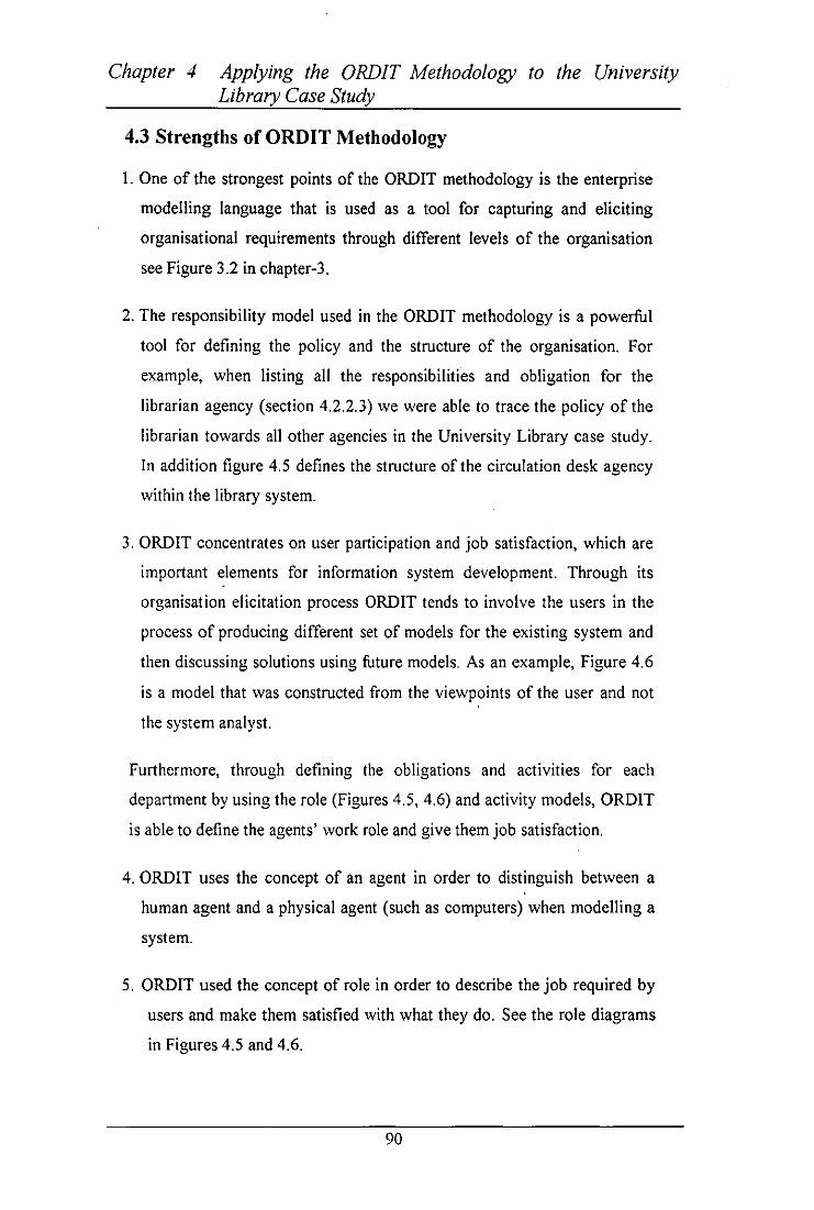
Chapter 4 Applying the ORDIT Methodology to the University Library Case Study
4.3 Strengths of ORDIT Methodology
I. One of the strongest points of the ORDIT methodology is the enterprise
modelling language that is used as a tool for capturing and eliciting
organisational requirements through different levels of the organisation
see Figure 3.2 in chapter-3.
2. The responsibility model used in the ORDIT methodology is a powerful
tool for defining the policy and the structure of the organisation. For
example, when listing all the responsibilities and obligation for the
librarian agency (section 4.2.2.3) we were able to trace the policy of the
librarian towards all other agencies in the University Library case study.
In addition figure 4.5 defines the structure of the circulation desk agency
within the library system.
3. ORDIT concentrates on user participation and job satisfaction, which are
important elements for information system development. Through its
organisation elicitation process ORDIT tends to involve the users in the
process of producing different set of models for the existing system and
then discussing solutions using future models. As an example, Figure 4.6
is a model that was constructed from the viewpoints of the user and not
the system analyst.
Furthermore, through defining the obligations and activities for each
department by using the role (Figures 4.5, 4.6) and activity models, ORDIT
is able to define the agents' work role and give them job satisfaction.
4. ORDIT uses the concept of an agent in order to distinguish between a
human agent and a physical agent (such as computers) when modelling a
system.
5. ORDIT used the concept of role in order to describe the job required by
users and make them satisfied with what they do. See the role diagrams
in Figures 4.5 and 4.6.
90

Chapter 4 Applying the ORDIT Methodology to the University Library Case Study
4.4 Weaknesses ofORDIT Methodology
1. DROIT methodology is not a complete system design methodology but
rather it is a methodology that identifies a series of complementary
activities for requirements capture. It is shown in the library case study
that DROIT finished when all the organisational requirements were
captured and specified.
2. Although the DROIT methodology adapts the socio-technical approach it
does not explain how the social and technical part of the system are
merged to ensure compatibility within the methodology, for example,
how the technical part of the system is evaluated against the job
satisfaction and future change.
3. The Problem Analysis process in DROIT methodology is not supported
by suitable tools for expressing and documenting the problems for the
problem owners in an organisation.
4. DROIT methodology does not address the business needs of the
organisation when modelling an information system.
5. DROIT does not address the business strategy of the organisation when
modelling an organisation.
4.5 Concluding Remarks
In this chapter DROIT methodology has been applied to the university library case
study to identify the strength and the weaknesses of the methodology. Some of the
strong points of DROIT's modelling techniques are the use of the enterprise
modelling language and a powerful responsibility model for defining the policy
and the structure of the organisation. DROIT also provides participation and job
satisfaction using concept of agents and concept of role. Although DROIT has
strong points it has its weaknesses too. The main weaknesses of the methodology
are failing to address the business needs and strategy for the organisation.
91

Chapter 4 Applying the ORDIT Methodology to the University Library Case Study
Using the responsibility model the problems of the library system are defined and
the boundaries are determined. Section 4.2.4 shows the modelling of the existing
system and the proposed changes that has to be implemented when modelling the
future system. In addition to user participation the methodology adopts the
iterative approach where users are consulted throughout the four stages. Section
4.2.5 is to do with modelling the new system that have the new requirements
which have been captured and elicited from users through applying the enterprise
modelling language.
92

Chapter 5 ISAC Methodology
ChapterS [SAC Methodology
5.0 Introduction
The purpose of using the ISAC methodology (Lundeberg, et aI., 1981) is to
evaluate the problem-oriented approach that is used in the change analysis phase.
Using the change analysis as a first stage in the proposed new methodology enable
the system developer and the problem owners to concentrate on identifying the
business problems in the organisation before starting to solve them. Another
benefit is finding out what changes should be aimed at to solve these problems.
5.1 ISAC Methodology
ISAC (Information Systems work and Analysis of Changes) is a methodology
designed for the development of information systems and anal ysi s of changes in
the organisation. Lundeberg, Goldkuhl and Nilsson developed ISAC in the early
seventies at the University of Stockholm (Lundeberg, 1982). The purpose of the
ISAC approach is to specify information systems in a number of small,
manageable, and connected steps in such a manner that both users and designers
understand the contents. As Michael et, al (! 986) concluded, Although the
methodology covers all aspects of information system development it has its
strength in the analysis and design stages only.
ISAC was developed in order to ensure that the business gets the information
system it needs. To reach this goal, it starts with an organisational problem
analysis that tries to find real solutions to the real problems. ISAC seeks to
identify the fundamental causes of users' problems in order to solve aspects of
them where appropriate.
"The methodology starts at an earlier stage than most methodologies and does not
assume that the development of an information system is necessarily the solution
93

Chapter 5 ISAC Methodology
to the problem" (Avison and Fitzgerald, 1988). If a solution requires an
information system development, then the methodology continues developing this
system by starting a detailed study of the business activities to be supported by the
system. If the development of an information system is not needed then the role of
the methodology terminates. The reason for this it is thought that an information
system that has no value in its own right and does not benefit people should not be
developed. This is why ISAC is considered as a client-oriented approach.
To increase the fit between the delivered system and the business needs, both the
problem analysis and the activity study includes a high degree of participation of
users, developers and sponsors of the information system. In these two stages the
users and sponsors analyse their problems themselves and perform an activity
study where the developer's role is to facilitate this process. This is because ISAC
authors believe that the people best equipped to do this analysis, in terms of their
knowledge, interest, and motivation, are the users themselves.
The ISAC methodology consists of five levels:
• Change Analysis
• Activity Studies
• Information Analysis'
• Data System Design
• Equipment Adaptation
5.2 Change Analysis
The purpose of change analysis is to identify the business problems and clarify
what types of changes are required in order to do something about the identified
problems and needs experienced in the activities of the organisation. This stage
concentrates on investigating where the problems really are before starting to try
to solve them. It contains the following steps:
94

Chapter 5 ISAC Methodology
5.2.1 List of Problems
The first step in the change analysis stage is to identify and create a list of the
existing problems and reach an agreement among problem owners, developers and
. the sponsors of the development process on these problems. A problem owner is a
person, group, stakeholders, agency, or user that is dissatisfied with the current
situation. Problem owners are called "interest groups" in ISAC but, because
ISAC is restricted to analysing problems and solving them for the problem
owners, it is better to use the term "problem owners".
The first attempt is to look at current problems and any anticipated future
problems. Table 6.1 in Chapter 6 is an example of a list of problems table.
5.2.2 Analyse the Problems
The problems identified are now subject to a cause-effect analysis. The reasons
for analysing the problems are to (I) concentrate on the problem itself not the
solution to the problem (this makes room for alternative solutions); (2) minimise
the problem list by concentrating on underlying problems only; (3) identify
derived problems. Specialist persons that have an expert knowledge of the
problems under study should perform the cause-effect analysis.
In addition, carrying out the cause-effect analysis, a quantitative study of the
problems must be performed. The benefit of this study is to enable us to assess the
severity of the problem before making a decision to invest in a solution process.
Quantifying the problems has three advantages. First, only a quantitative
characterisation of these problems can give an indication of the potential benefit to
be derived from solving the problems. Second, only if a problem is quantified it is
possible to know in the future whether and to what extent it is solved. Third, if
quantification shows that a problem has only a slight impact on the business, the
sponsor may make only a small budget available for solving it, or the problem
owners may drop it from the problem list completely. For the unquantified
problems, it will be harder to know in the future whether and to what extend they
are solved than it is for the quantified problems.
95

Chapter 5 ISAC Methodology
5.2.3 Making an Activity Model of the Current Business
At this stage an activity model (A-graph) is developed to represent the activities
performed in the current business situation and the flow of material information
between those activities. These activities are the ones to which the identified
problems relate and which are undertaken by the concerned problem owners. The
activity model is a functional view that shows processes performed on inputs to
produce output. Therefore, it is used as a platform for generating and discussing
alternative solutions and discussing possible changes to the business in the next
step. Figures 6.1 through 6.9 in Chapter-6 are examples of A-graph models.
An A-graph represents three things:
I. Sets which can be: real or physical sets, like, for example, people or
documents; message sets, containing only information; or they can be a
combination of both.
2. Organisation activities.
3. Flows which can be shown in detail or simply as an overview.
Activities are the transformation of sets into new sets. Flows represent the
movement of sets to and from activities. They are very similar to data flow
diagrams, except they also represent physical objects as well as data flows. Figure
6.1 in Chapter 6 shows an example of an overview A-graph concerned with the
Circulation Desk of the library. A-graphs depict a hierarchical structure capable of
showing an overview picture, which can then be broken into other A-graphs to
show the detail at lower levels. Each A-graph is supplemented with text and
property tables. The property tables show quantitative information such as
volumes.
5.2.4 Analyse Goals
A goal is a desired situation. The problem owners identified before have different
general goals. These goals can be found by interviewing problem owners and
asking them questions about the situation they would like to achieve.
96

Chapter 5 ISAC Methodology
At this stage goals of the development process are specified and listed to find a
means to evaluate solution proposals. Making a list of goals may require a lot of
negotiation, because different problem owners may have contradictory goals, and
agreement between them is at least desired on the business mission. Table 6.8 in
Chapter-6 is an example of the Library goal analysis.
5.2.5 Define Change Needs
One of the reasons for developing the list of goals is to find out why the problems
identified above are problems at all. Conversely, for each goal we can identify the
reason why it has not been achieved by listing all the problems that prevent the
goal from being achieved. Therefore at this stage a matrix of problems against
goals is developed to find clusters of related problems. Each cluster defines a
change need that will act as a goal of the development process. Table 6.9 in
Chapter-6 is an example of the Library change needs.
At this stage all the previous work comes together and enables the methodology to
progress. What is needed (the goals) is compared to what is available. The
differences between what is needed or wanted and what is available are defined as
the needs for change. These needs are prioritised according to the values of the
different problem owners involved. This evaluation of the importance of the
various needs for change leads directly into the next stage, which is the generation
and study of change alternatives.
5.2.6 Generate Change Alternatives
At this stage all ideas are written down without evaluation or critique and
summarised in a table of change alternatives. Once possible changes have been
generated they are described through a new A-graph. Table 6.10 is an example of
change alternatives.
5.2.7 Make Activity Model of Desired Situations
In order to be able to evaluate the results of the alternative packages, each change
alternative package is described in a new activity model (A-graph with text pages
97

Chapter 5 ISAC Methodology
and property table). Figures 6.3 and 6.4 are examples of A-graphs models for the
desired situation.
5.2.8 Evaluate Alternatives
For each alternative package that is modelled, estimation is made of their problem
solving power. Each package is analysed and evaluated for different viewpoints,
e.g., human, social, and economic. This is to investigate which problems are
solved and which ani introduced by each package. Table 6.13 is an example of an
alternative evaluation.
5.2.9 Choose an Alternative
The last part of the change analysis is to choose a change approach. The sponsor
is presented with a report about the evaluation of alternatives and then chooses
one of them. The developer may suggest a choice, but it is important that the
sponsor authorises it. If the recommended changes do not involve information
systems then the' role ofISAe methodology terminates.
5.3 Activity Study
If the recommended changes involve a new information system then it will be
possible to continue with this step by modelling and describing the new system in
a number of ways using A-graphs. The activity models that were produced in the
change analysis for the purpose of identifying needs for change were at an
overview level, and these need to be decomposed and investigated.
The purpose of this stage is to decompose these overview activity models into
information subsystems, specify required subsystem properties, and specify
interfaces between the subsystems. The objective is to reach the level where the
information system is separated from the human activities, which it supports, such
that each process on the graph has input and output that are either information or
some other flow, for example, materials.
98

Chapter 5 ISAC Methodology
5.3.1 Decomposition into Information Subsystems
The chosen model is elaborated until information systems can be identified. For
each desired information subsystem, it is determined whether it is formalisable or
. not. An example of an unformalisable information system would be informal
contacts, know-how and so on. The formalisable subsystems are divided into
those that can be automated in terms of cost, social desirability, etc, and those that
can not. The automated subsystems are further classified according to whether
they involve calculations or involve storing and retrieving information. Figure 6.6
is an example of the decomposed borrowing activity at the library.
5.3.2 Analysis of Information Subsystems
For each system to be automated, desired properties, called ambition levels are
specified, then each ambition is tested for feasibility. [SAC recommends the
following ways of testing feasibility:
• Find out if projects with similar objectives have realised information
systems with similar ambition levels.
• Simulate the ambition levels.
• Build a prototype that satisfies a number of the properties of an
ambition level and do a field test with it, i.e. let users actually work with
it.
• Carried out a cost-effect analysis for each identified level of ambition.
Ambition levels
At this stage of the activity study each information system is studied separately in
terms of its cost and benefits. It is also determined whether it could be automated
or not. This is done by classifying each information system under one of the
following steps:
99

Chapter 5 ISAC Methodology
1. Impossible to formalise: An example of this type of information
subsystems is informal activities in which information is exchanged with
the client informally.
2. Formalizable subsystems:
A) Not.automated system: For example photos can be scanned and
then printed in order to be stored in manual archives or
digitised and stored in computer memory. Due to reason of
privacy, however, it may be decided that this activity is not
suitable for automation.
B) Automated systems: The library circulation desk is an example
of this.
5.3.3 Co-ordination of Information Subsystems
The activity study ends with an analysis of the relation between the different
information subsystems, and the assignment of priorities to them.
5.4 Information Analysis
The purpose of information analysis is to describe what the future information
system will contain and how it will be performed. This stage will not be
performed until one or more information systems have been identified as
formalisable. The techniques used in the information analysis assume a
formalisable and automatable information system, although it is indicated that a
limited degree of information analysis might be appropriate for non-automatable
systems.
For each information system, the input and output information sets are extracted
from the A-graph for the system. At the same time, an iterative process of function
and data analysis is performed. Method steps used in the information analysis
are:
100

Chapter 5 ISAC Methodology
5.4.1 Precedence and Component Analysis
Precedence analysis involves the analysis of the information precedence relations
in an information system, where component analysis involves the analysis of the
structure of information sets. This is the ISAC term for functional analysis. The
analysis of information precedence relations is documented in I-graph and text
pages. The nodes of the I-graph represent information precedence relations and
the process are disregarded, this precedence analysis is hierarchical and starts with
overview descriptions, which are elaborated and detailed successfully (see Figure
6.10 as an example). If the output information set from an information system is
clearly derivable from its input set then precedent analysis stops. If, however, the
derivation is not clear, then the information set that immediately precedes the
output information set must be deduced. If the derivation of this set from the input
to the system is not clear, then precedent analysis continues. The precedents from
each information set are analysed until the input sets are reached. Precedence
analysis is in this way equivalent to functional decomposition in other
methodologies. Reasoning about the transformation that needs to be performed on
information sets requires knowledge of the structure of information, and that is
why component analysis is performed at the same time as precedence analysis. In
component analysis the structure of the information sets is studied and classified
into one of the following:
• A basic input to the information system.
• A basic output from the information system.
• Information coming from a preceding process or a set of permanent
information.
An information set may be compound, that is, it may itself contain information
sets. An elementary information set consists of one or more messages, where each
message consists of an identification term and one property term. An "almost
elementary" information set consists of a number of elementary information sets
with common identification terms. Thus an almost elementary information set
101

Chapter 5 ISAC Methodology
corresponds to a logical record with an identifying key and a number of data item
types (property terms). The component analysis is documented in a C-graph which
is a hierarchy showing the decomposition of an information set into subsets (see
. Figure 6.11 as an example.).
5.4.2 Process Analysis
In this step the information processes are identified and documented in a list of
processes. The reference code from the I -graphs is used to keep track of these
processes. An information process is the transformation of one or more
information sets into some other information sets or set. These transformations are
at the logical level, and do not show the representation or implementation aspects.
Each process can be described separately, the description is documented in
process table (decision tables) which consists of two parts: prerequisite and
calculation. Table 6.20 is an example of the process analysis table.
5.4.3 Property Analysis
The property analysis is a continuation of the property descriptions already made
during change analysis and activity studies. Requirements that are specific to the
environment in which the system is used must also be specified. The relevant
property values are documented in property tables. Examples of such properties
are volumes, response time, frequency, and security requirements.
5.5 Data System Design (DSD)
Up to this stage the ISAC activities of change analysis, activity studies and
information analysis have concentrated on producing a specification of
requirements for information systems. The purpose of the data system design is to
design a technical solution to meet the requirement specification and to prepare an
equipment-independent data system solution to the specified information
subsystem. Therefore it is the first part of the data-oriented system work. In the
data-oriented system work a processing philosophy is considered in order to
distinguish between manual and automated parts, both of which must be designed.
102

("'-------_I
Chapter 5 ISAC Methodology
During the activity studies a distinction is made between manual and automatable
parts of an information system (see, e.g., Table 6.20 in Chapter 6). During the
information analysis stage the information contents of the automat able parts are
. described in detail. In data system design a decision must be made about future
ways of processing. For example, what part of the data system should be manual
processing, manual processing with technical aid, computer solution with patch
processing, computer solution with direct processing or other automated
processing. Also at this stage a decision must be made on which systems should
be centralised and which systems should be distributed with the consideration of
cost and reliability.
The next step of data system design is data structure design and program
delimitation. During the information analysis stage decomposition has been made
to data and functions below the level of files and programs. The design of a
permanent data set is performed by consolidation of these data set (for example,
elementary information sets) into higher-level groupings on the basis of functional
dependency, and secondly, by considering access method requirements and search
paths for efficient retrieval and storage.
Program delimitation consists of putting a boundary around a group of process
defined in the I-graph. The number of processes grouped will partially determine
the size and complexity of the program, and these two factors are a constraint on
the delimitation. The other important constraint is the nature of the decisions that
have been made about file and database design.
The next step is to specify each program, which is completed in some detail in the
ISAC approach, and the "Jackson Structure Processing" method is recommended
at this stage.
The last step of data system design is the design of manual parts. During the study
of processing philosophy it has been decided on which parts of the automatable
information subsystems were to be automated and which were to be manual.
ISAC suggests that the affected problem owners should participate in the design
of the manual system.
103

Chapter 5 ISAC Methodology
5.6 Equipment Adaptation
The purpose of this section is to choose specific equipment and then to adapt the
equipment-independent solution to this choice. The data system design has
produced an equipment-independent solution and a decision has been made on a
suitable solution. This is now adapted to fit a particular equipment. Equipment
adaptation consists of:
5.6.1 Equipment Study
During the equipment study a decision must be made on specific equipment. This
decision depends on the following factors:
• Identification of alternative equipment strategies: The alternatives that
could be defined are use available computer capacity within the
company, use a service providing company and purchase or rent a new
equipment.
• Calculation of the size of the computer system: For each configuration
(equipment strategy) the necessary resources are calculated, e.g.,
volumes, response time, printer speed and memory capacity.
• Manufactures introduction: Information is collected about manufacturers and
distributors, which can provide the equipment needed, and their prices for
each alternative specification.
• Evaluation of equipment strategies: the advantages and disadvantages
of the alternative strategy are compared with selected decision criteria.
The result is documented in an evaluation table.
• Choice of suitable equipment: The final choice of equipment IS
documented with supplementing property tables.
104

Chapter 5 [SAC Methodology
5.6.2 Adaptation of Computer-Based Routines
The adaptation of computer-based routines is done in two main steps:
• Design of physical data structure: At this step the technical storage and
equipment aspects of data structure are considered.
• Design of adaptation routines: A special routine called an adaptation
routine is designed that can transform physical structures into an
equipment-independent structure.
5.7 Tools Used in ISAC Methodology
ISAC uses three activity models as a graphic description techniques which take
the design process through different levels of abstraction, leading from activity
analysis (A-graph) to information subsystem analysis (I-graph) to component data
analysis (C-graph). These graphs are closely related to each other as one can
complete the oth.er.
5.7.1 A-graph
An A-graph describes an activity in the organisation as a set of interrelated
subactivities. Each subactivity can be described in a more detail on a separate A
graph. Through the analysis and description of subactivities a hierarchy of A
graphs is created. An A-graph is constructed in the change analysis phase to
describe the current situation and in the activity study phase to describe the
alternatives of the change situation in the future.
5.7.2 I-graph
An I-graph is used in the information analysis phase. An I-graph describes
information sets and precedence relations between information sets. A-graphs are
needed to build the I-graphs. They are more precise than A-graphs in that they not
only show input and output sets but also show relationships between sets. The 1-
graph is described by which precedence relationship connect the outputs of the A
graph with the inputs. So activities of the A-graph are decomposed.
105

Chapter 5 ISAC Methodology
5.7.3 C-graph
C-graph and an I-graph are both constructed during the information analysis
phase, therefore there is a close relationship between the two graphs. Precedent
analysis, resulting in an I-graph, and component analysis, resulting in a C-graph,
are performed in an iterative process. A C-graph describes the structure of
information sets. An information set depicted in an I-graph maybe compound and
it may itself contain information sets. So a C-graph is a hierarchy graph showing
the decomposition of an information set into subsets.
5.8 Concluding Remarks
ISAC methodology is designed for the development of an information system and
analysis of change in an organisation. The main purpose of the methodology is to
specify the information system in small manageable and connected steps.
ISAC consist of five stages, which concentrate on users and business mission of
the organisation. These five stages are Change Analysis, Activity Study,
Information Analysis, Data System Design, and Equipment Adoption. During
Change Analysis, current business problems are analysed, different solutions are
investigated and one solution is chosen. The chosen solution is modelled using an
A-graph. This A-graph depicts a high level specification for the required business
situation in terms of its activity. Change Analysis is a general problem solving
method. If the solution involves building one or more information systems, then
the Activity Study determines the required information system properties. In
addition, the important decision whether or not to automate one or more
information systems is made. For each system to be automated, an Information
Analysis is performed, which results in a behaviour specification for each
automated system. As Wieringa, (1996) stated, the term "Information Analysis" is
misleading, because in most other methods it is for the initial stage of information
system development or information needs analysis. The final stage is the
Equipment Adaptation, which involve finding of the most appropriate computer
system for the organisation.
106

Chapter 6 Applying ISAC to the University Library Case Study
Chapter 6
6.0 Introduction
Applying [SA C to the University Library Case Study
In this chapter ISAC methodology will be applied to the University library case
study that was used in chapter 4. The validation of the hypothesis (see chapter 1)
against this case study will take the following two forms.
• The ISAC methodology is used in order to model the existing system
and provide solutions to the problems of the University Library. The
business mission and strategy of the library organisation are identified as
well.
• Through applying ISAC to the case study, it is possible to highlight the
strengths and weaknesses of the methodology.
6.1 Change Analysis
The first phase of ISAC methodology is the change analysis, which contains the
following tasks:
6.1.1 List of Problems
Using the ISAC approach for the library case study an initial meeting has to be
made with the Head librarian. The developer learns about a number of problems,
which he/she writes down as follows.
107

Chapter 6 Applying ISAC to the University Library Case Study
Problems Description Related No Name Activities Sets in
A-graph PI Documents are lost Too many documents are stolen
or stolen from shelf or stolen 61l1A, 2A P2 Documents are Documents are kept too long by
returned late library members 631A P3 Too many Due to the previous problem
reservation there are too many reservation in proportion to borrowing 6C2,621A
P4 There are no There are no reliable Statistics reliable use of of the use of the documents and statistics of their availability. 6C
PS The budget will Due to the cuts in university shrink over the next funding by the government, the few years budget is shrinking.
P6 The current Scientific publishers tend to budgets is double the subscription rate L4 overspent every few years
P7 The dollar rate is Most subscriptions are in US fluctuating dollars, which can cause
unpredictable rises in the cost of iournal subscription.
Table 6.1: List of problems
Each problem from the above Table 6.1 is studied and analysed in order to
determine whether it is worth devoting a development process or not. The
problems that are easy to solve or very difficult to solve for example, PS and P7,
are eliminated from the development process. The reason for writing the problems
in the problem list and then eliminating them is to let the users be aware of them,
talk about them, and then reach an agreement that, at least at this stage, they
should be ignored.
6.1.2 List of Problem Owners
After identifying the problems to be solved, the next step is to identify the groups
of people or agencies that are affected by the same problems. This task is similar
to the steps performed in the second stage in OROIT methodology where the
boundaries to the problems are identified. Stakeholders and agencies that are
within the system or have an effect on the new system are also identified.
108

Chapter 6 Applying ISAC to the University Library Case Study
Representatives from each of these groups or agencies should participate in the
project team.
A matrix of problems against problem owners is developed at this stage as shown
in Table 6.2. Identifying the problem owners (stakeholders, agencies, and end
users) requires social skills, because some groups or agencies may be interested in
suppressing the interest of others. The system analyst must ensure that the
problem owners themselves, facilitated by the developer, should construct the
matrix connecting the problems with problem owners.
Problem Owners Problems Activities in No. A-2raph
Faculties PS C4 Library Member PI,P2,P3 C6
Librarian PI, P2, P4,PS C6 Treasurer PI, P4, PS C4, CS,C6
Circulation Desk PI,P2,P3 C6
Table 6.2: Initial matrix of problems against problem owners
6.1.3 Analysis by the Interest Group
This process is performed by the project group (which may consist of a
representative from the Treasurer, representative from the Circulation Desk, end
user of the required system, an outside specialist, and Head librarian.) who have
expert knowledge of the problems under study. These people have to do a cause
effect analysis for the problems that have been identified. The first version of the
problem table of the library case study is depicted in Table 6.1.
During the cause-effect analysis for the library case study, a number of important
problems were discovered. One cause of overspending the budget is that different
departments multiply acquire documents and some of them have subscriptions to
the same journals. This is called the problem of multiple acquisitions. The
problem of multiple acquisition and lack of coordination are added to the problem
list.
109

Chapter 6 Applying ISAC to the University Library Case Study
The problem of the high reservationlborrowing ratio is caused by the poor
availability of books, which is in turn caused by the two problems of
losing/stealing books and of not returning books. One of the causes of lost/stolen
books is improper supervision on the return of documents, which makes it
possible for library members to steal a book that someone else returned but has
not yet been registered as received by the library. Another cause of lost/stolen
documents is that all books and journals are stored in rooms open to the library
members, so that they can browse through them but can also easily steal them.
This problem is added to the problem list.
The librarian insisted that an important cause of lost/stolen documents and of the
fact that documents are kept too long is bad member mentality. It is quite possible
to see this as a fact of nature, like the problems of shrinking budgets and
fluctuating dollar rates, but the librarian believes that an education campaign can
change this mentality, so the developer added it to the problem list and cause
effect graph.
Finally, it was discovered during the analysis that one cause of the overlong
borrowing period is that library personnel have no time to go through the list of
borrowed books each week to find out which books have been borrowed longer
than their allowed borrowing period. Manual procedures also increase the cost of
levying fines. The problem list is updated accordingly as it is seen in Table 6.3.
110

Chapter 6 Applying ISAC to the University Library Case Study
Problems Description Related No Name Activities Sets
in A-graph PI Documents are lost or Too many documents are 6111A, 2A
stolen stolen. P2 Documents are Library members keep 631A
returned late documents too long. P3 Too many reservations Due to the previous problem
there are too many 6C2,621A reservations in proportion to borrowing.
P4 There are no reliable There are no reliable Statistics statistics oflibrary of the use of the documents 6C use. and of their availabilitv.
P5 Overspend budget Scientific publishers tend to double the subscription rate 4C everv few vears.
P6 Multiple acquisition Documents are mUltiply acquired by different departments, and have 4B subscription to the same iournals.
P7 No coordination of There is no coordination acquisition between department for L4
acquiring documents. P8 Sloppy return Improper supervision on the
orocedure return of documents. L631 P9 Bad member mentality Members keep documents too
long. L631 PlO Open store All documents are stored in
rooms open to members. LO PII Manual procedure The procedure of borrowing
and returning documents is L6 manual.
PI2 Cost of not levying When document are returned fines late no fine is charged. L5
Table 6.3: Matrix of final problems after updating
III

Chapter 6 Applying ISAC to the University Library Case Study
The matrix of the problems against problem owners is updated as well and
depicted in Table 6.4.
Problem Owners Problems A-graph Faculties ------.. ------
Library Member PI ,P2,P3 ,P8,P9 C6 Librarian PI,P2,P4,P5,P6,P7,PIO,
PI2 C6 Treasurer PI,P4,P5,P6,P7,PII,PI C4,C5,C6
2 Circulation Desk P8,P9,PII C6
Table 6.4: Matrix of the problems against problem owners
6.1.3.1 Property table
In addition to doing a cause-effective analysis, a quantitative study should be
made of the problems see Table 6.5. The reason for this is to decide whether to
invest in the solution process or not, therefore the severity of the problems must
be assessed first. For example, how many documents are stolen each year? For
how long do borrowers exceed allowed borrowing periods? What is the ratio
between reservation and borrowings?
In the library case study, it was found that not all problems could be quantified. It
can be seen from Table 6.5 that the cost of not levying fines is a negligible
problem compared with the other problems.
112

Chapter 6 Applying ISAC to the University Library Case Study
Problems Identified Problem Quantification PI. Too many A total of 4500 titles are known to have been stolen. documents are stolen. On the average, 200 titles are stolen each year, with
an increase of 10% per year P2. Members keep On the average, a document is returned three weeks documents too long. after it ought to be returned. P3. There are too The average ratio is 30 reservation for every 10C many reservations in borrowings, with an observed maximum of 50 per proportion to 100. borrowings. P4. There are no All figures in this table are estimates. reliable statistics for I ibrary use. P5. The budget is over- The current annual budget of Ofi 900 000 is overspent spent. by Ofi 200 000. P6.Multiple 20% of the 3000 journal subscriptions are duplicates. acquisition P7. No coordination of Not quantifiable. acquisitions. P8. Sloppy return Not quantifiable. procedure. P9.Bad member Not quantifiable. mentality. PlO. Open store Not quantifiable. PI I. Manual Not quantifiable. procedure P 12. Cost of not Approximately Ofi 900 is not collected a year. levying fines
Table 6.5: A quantification matrix of some identified problems
6.1.4 Description of Current Activities
At this stage the activities related to the identified problems and the activities
undertaken by the concerned problem owners are modelled in an activity model
called an A-graph, which depicts the functional view of the library system and
shows processes performed on input to produce outputs. These aspects are not just
concerned with information, but includes physical activities, input and outputs,
such as the information real set collecting a book (6B) in Figure 6.1. The activity
model is supplemented with text-pages in order to document it, see Table 6.6.
113

Chapter 6 Applying ISAC to the University Library Case Study
A-graphs are similar to data flow diagrams, except that they also represent
physical objects as well as data flows as can be seen in Figure 6.1.
LIB Analyst Asad AI-Zaid Subject: University Library
Overview
LO
A-GRAPH Date 8 August, 1997
Administration
Figure 6.1: A-graph for a university library
114
I No. LO Version 1

Chapter 6
LIB Analyst Asad AI-Zaid
Applying ISAC to the University Library Case Study
Date
TEXTPAGE A-GRAPH
8 August, 1997 I No. LO Subject: Library Activities Version I
Overview
lA Publisher Confinnation for lib Acquisition 1B New Ordered Documents IC Document Billing
2A Lost Documents Information 3A Borrow or Renew Request Information
3AI Borrow Request Information 3All Borrow Book Title 3AI2 Borrow Member ID
3A2 Renew Request 3A21 Borrow Book Title 3A22 Renew Member ID
3B Documents Return 3C Document Reservation
~ Financial and Acquisition Activities ~A Documents Budget Infonnation to Circulation Desk
5 Administration Activity 6 Circulation Desk
6A New Document Order Information to Financial
~B Document Order 4C Document Payment 5A Invoice 6B Book 6C Not Available Document Information
6Cl Book is Borrowed 6C2 Book is Reserved
Table 6.6: Text pages to A-Graph LO
115

Chapter 6 Applying ISAC to the University Library Case Study
Figure 6.1 above shows an A-graph with an overview of the activities in
connection with the University Library. Table 6.6 shows a text page for this A
graph. The A-graph in Figure 6.1 illustrates three main activities or process:
• Financial and Acquisition
• Administration
• Circulation Desk
It also shows all the input and output information from these processes. For
example, when the financial department wants to pay for a document, they would
need to know the title of the requested document, the price of the new document
and whether the document has been ordered before. The output information from
the financial process contains the document that is ordered, and the invoice that is
paid.
An explanation of how to use the graph is as follows: the input message sets "Title
confirmed", "Document bill" and the real set "New document" flows into the
activity "Financial". This activity produces two outputs message set which are
"Document order" and "Document payment". Also the message set "Lost
document information" flows into the activity" Administration" to produce an
output message set called "document invoice". In the same manner, the input
message sets "BorrowlRenew request", "Document reservation" and the real set
"Document return" flows into the activity "Circulation desk". This activity results
in two message sets "financial information" and "Document information" and two
output sets which are the real set "'Book" and message set " Not available
document information".
116

Chapter 6
LIB Analyst Asad AI-Zaid
Applying ISAC to the University Library Case Study
A-GRAPH Date 8 August, 1997 I No. L6
Subject: Circulation Desk Version I
Overview
le
L6 rrowing&Renewal
Figure 6.2: A-graph L6 for circulation desk
I 17

Chapter 6
LIB Analyst Asad AI-Zaid
Applying ISAC to the University Library Case Study
Date
TEXTPAGES A-GRAPH
8 August, 1997 I No. L6 Subject: Circulation Desk Version I
Overview
3A
3B 3C
61
62 63
6B
6D
3AI
61A
63A
6CI 6C2 6C3 6C~
3AIl 3Al2
Borrow or Renewal Request Borrow Request Information Borrow Book Title Borrow Book ID Document is Return from Member Reservation Request from Member
Document Borrowing and Renewal Request for Checking Title Reservation Reservation Activity Return Document Activity Documents Status Information
Book Book is Borrowed Book is ReSeIyed Reservation Request Rejected Reservation Request Confinned Late Fine for Late return Documents
Table 6.7: Text page to A-graph L6
118

Chapter 6 Applying ISAC to the University Library Case Study
An in-depth description of the activities at the circulation desk is found in Figure
6.2. The three subactivities that can be performed at the circulation desk are;
• 80rrowing Renewal (L61),
• Reservation (L62)
• Return (L63).
To start by considering the flow of information in the A-graph (L6) Figure 6.2, it
is found among other things that documents are borrowed (3A), reserved (3C) or
return (38) by members through the circulation desk (L6). If member wants to
borrow a document from the library he/she has to go to the circulation desk to
place her/his request. When a borrow request flows to the borrowing activity
(L61), the activity consists of checking to see if the document is available and not
already reserved (611A). If the document is reserved (6C2), the borrower must be
the same person as the reserver to be able to borrow the document (6Cl),
otherwise the request is rejected (6C3).
At the Reservation activity (L62), Figure 6.2, documents are checked for
reservation. If document is already reserved and the request for reservation is
performed from the same account then, document reservation request is confirmed
(6C4), otherwise it is rejected (6C3). If the document is not reserved then this
information has to be sent to the borrow and renewal activity to release the
document for borrowing or renewal.
At the Return activity (L63), documents are returned by a member to be stored on
the library shelves. The document's return information is sent to reservation (L62)
and borrow activities to inform them that the document is returned. Reservation
(L62) will check to see if the document is reserved otherwise it is released for
borrow (61128), see Figure 6.6. Since all members can borrow documents some
regulation has to be enforced to get the document back within a certain period of
time. If a document is not returned within the allowed period of time a reminder
has to be sent to members, especially when document is reserved by another
member. If document is not returned after the second reminder then a late fine has
to be issued for the members.
119

Chapter 6 Applying ISAC to the University Library Case Study
When members lose a document, they have to report it to the Administration (LS),
Figure 6.1, in order to issue an invoice (SA) for the price of the document.
The Financial activity (L4) has to pay for the new ordered documents that are
acquired from the publishers. In the existing system duplicate acquisition problem
is performed by the different departments at the university. This problem will not
be solved at this time however, the circulation desk problem is the only problem
that will be explored in this thesis.
Previous activities in Figure 6.2 are more described by dividing them into
subactivities and decomposing them in new A-graphs. For example, process 6 in
Figure 6.1 is decomposed into (L61, L611, L612, L62, and L63) to solve the
previous problems with the proposed system of the Circulation Desk. In the
decomposed graphs, it is important that different graph level~ must have exactly
the same input and output sets for the same activity. However, sets maybe
subdivided into subsets if necessary. In Table 6.7, the Borrow and Renewal
activities are separated in order to give more detailed description of each process.
The idea of the decomposition process is to get to the level where the information
system is separated from the human activities which it supports, such that each
process on the graph has inputs and outputs that are either information or some
other flow, like materials. In figure 6.6, when borrow request arrives, the member
has to present the name of document (3AII) and his/her ID, (3AI2) to the Borrow
Activity Desk (L611). A document check has to be performed to see whether the
document is borrowed (6CI) or reserved (6C2). If document is available (not
borrowed or reserved) the member will collect the document (6B) from the
library. If document is not borrowed and not available it is considered to be lost
(611IA), thus the final library index for that document is updated (L6112A).
When member wants to renew a borrowed document, the document is checked for
reservation (6IB). If the document is not reserved the renewal request is
confirmed (612B), otherwise the renewal request is rejected (612C).
In the A-graph no. L62, Figure 6.8, the reservation activity is described. When a
reservation request arrives, the member has to provide the title of the document
120

Chapter 6 Applying ISAC to the University Library Case Study
(3C2) and member ID (3CI) in order for the reservation activity to perform
his/her reservation request. The checking reserved activity (L62) consist of
checking to see whether the document is available and is not reserved. If the
document is reserved, the reservation request is rejected (6C4). If the document is
not reserved, the reservation request is accepted (62IA) and the reservation record
is confirmed (6C5). When the member collects a reserved document then the
reservation request is deleted (62IB).
The last A-graph L63, Figure 6.9, describes the Return and Follow-up activities in
more detail. When a document is returned, the return activity (L63 I ) will check
whether the document is reserved to see if it must be placed on the reservation
shelf and to check whether the returned document is late (63 I lA) or not. If the
document is not returned on time and a second reminder is send to the member,
the follow-up activity will issue a late fine (6E), which has to be paid before
members can use the library again. When a document is returned on time and is
not reserved, the Return activity puts it in the right place and updates the
appropriate records accordingly.
Text pages
Text pages must come with each A-graph in order to document the contents of the
sets and activities in more details. A text page is divided into three parts. The
input sets are listed in the first part, the sets and activities within the frame are
listed in the second part, and the output sets are listed in the third part. Table 6.6
and Table 6.7 are examples of the text pages.
The description of the current system can now be evaluated against the problem
table in (Table 6.3). The test for evaluating whether the current description has
been properly completed is whether all the relevant problems can be related to the
current description. The right column of Table 6.3 relates the problems in the
problem table to the activities and sets of the A-graphs. The right column of Table
6.3 shows that it has been possible to relate the entire problems in the problem
table to the description of the current situation. Hence we can continue with the
next step.
121
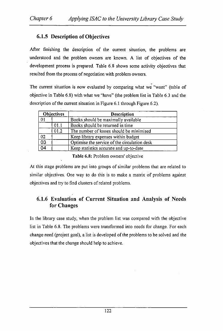
Chapter 6 Applying ISAC to the University Library Case Study
6.1.5 Description of Objectives
After finishing the description of the current situation, the problems are
understood and the problem owners are known. A list of objectives of the
development process is prepared. Table 6.8 shows some activity objectives that
resulted from the process of negotiation with problem owners.
<>
The current situation is now evaluated by comparing what we "want" (table of
objective in Table 6.8) with what we "have" (the problem list in Table 6.3 and the
description of the current situation in Figure 6.1 through Figure 6.2).
Obiectives Descriotion 01 Books should be maximallv available
01.1 Books should be returned in time 01.2 The number oflosses should be minimised
02 Keep library expenses within budget 03 Ootimise the service of the circulation desk 04 Keeo statistics accurate and uo-to-date
Table 6.8: Problem owners' objective
At this stage problems are put into groups of similar problems that are related to
similar objectives. One way to do this is to make a matrix of problems against
objectives and try to find clusters of related problems.
6.1.6 Evaluation of Current Situation and Analysis of Needs for Changes
In the library case study, when the problem list was compared with the objective
list in Table 6.8. The problems were transformed into needs for change. For each
change need (project goal), a list is developed of the problems to be solved and the
objectives that the change should help to achieve.
122

Chapter 6 Applying ISAC to the University Library Case Study
Needs Description Problems Priority Obiectives NI Return procedure should P2, P3, P8, PII I 01,03
be improved so that documents available and the service to the customer are maximised.
N2 Acquisition should be P5,P6, P7 3 02 coordinated so that multiple acquisitions are reduced
N3 Statistics should be P4 2 04 improved
N4 The possibility of theft PlO I 01 should be reduced.
Table 6.9: Table of change needs
In the rest of the case study we will concentrate on the three needs for change with
the highest priority: NI, N3 and N4.
6.1. 7 Study of Change Alternatives
[SAC gives no guidance on how to generate ideas for change, except to say that an
analysis of flows and activities might be helpful. Change alternatives can be
reached after meeting with the problem owners. At this stage, alternatives are only
ideas written down without evaluation, there are no exact rules for doing them.
Evaluation will be done in the next step. During the change alternative process we
have to investigate different alternatives of changing flows and/or activities. Can
the flow occur in another way? Can the activities be performed in another
manner? The answer to these questions leads to the change alternative document
in Table 6.10.
123

Chapter 6 Applying ISAC to the University Library Case Study
Altern Description atives
AI Reduce theft by removing all documents from the reach of members A2 Reduce theft by making all books with an indelible and invisible
magnetic marker and place ports with sensors at library exits. A3 Improve supervision on document return procedures by reducing the
number of entries/exits to the library to one, and by organising a strict schedule under which there will always be one library functionary at the entry/exit desk.
A4 Facilitate the production of use statistics by implementing an automated information system.
AS Facilitate automatic reporting on members who extend their borrowing period beyond allowable limits by implementing an automated information system.
Table 6.10: Table of change alternatives
Looking at the alternatives above in Table 6.10 it is realised that some of them
involve changes to the information system of the library, including automation:
others take measures not involving automated information system.
6.1.8 Make Activity Model of Desired Situations
Now it is possible to make packages of one or more change alternatives that are
worth investigating. To investigate a package, an activity model has to be
developed. This makes the package a possible topic of rational discussion and
allows comparison with the current situation.
In the university library case study there are a number of packages that can be
constructed from the available alternatives.
1- Change nothing at all. This package should always be included, simply because
the possible changes has to be compared with the current situation.
2- A I: Put all documents in a separate storeroom.
3- A2 & A3: Use magnetic markers and reduce the number oflibrary exits.
4- A4 & AS: Implement an automated information system.
A-graph models of the alternative packages are then developed for presentation to
the problem owners. This is to make the problem owner look at the models, study
them and choose the most suitable model for them with the help of the developer.
124

Chapter 6 Applying ISAC to the University Library Case Study
LIB Analyst Asad AI-Zaid Subject: University Library
Overview
A-GRAPH Date 8 August, 1997
Administration
Figure 6.3: A-graph LO for university library
125
I No. LO Version 1
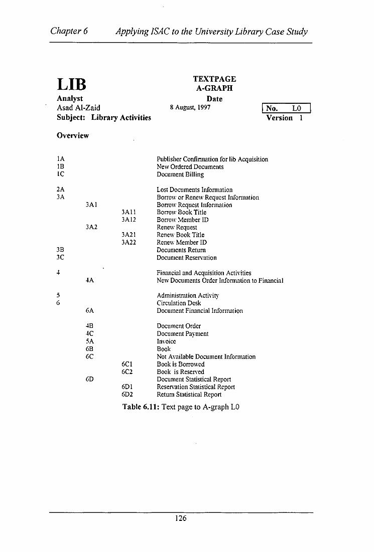
Chapter 6
LIB Analyst Asad AI-Zaid
Applying ISAC to the University Library Case Study
TEXTPAGE A-GRAPH
Date 8 August, 1997 I No. LO
SUbject: Library Activities Version I
Overview
lA 18 lC
2A 3A
3Al
3A2
3B 3C
~
4A
5 6
6A
~B
K 5A 6B 6C
6D
3All 3Al2
3A2l 3A22
6Cl 6C2
6Dl 6D2
Publisher Confinnation for lib Acquisition New Ordered Documents Document Billing
Lost Documents lnfonnation Borrow or Renew Request Information Borrow Request Information Borrow Book Title Borrow Member ID Renew Request Renew Book Title Renew Member ID Documents Return Document Reservation
Financial and Acquisition Activities New Documents Order Infomlation to Financial
Administration Activity Circulation Desk Document Financial Information
Document Order Document Payment Invoice Book Not Available Document Information Book is Borrowed Book is Reserved Document Statistical Report Reservation Statistical Report Return Statistical Report
Table 6.11: Text page to A-graph LO
126

Chapter 6 Applying ISAC to the University Library Case Study
LIB Analyst
Asad AI-Zaid Subject: Circulation Desk
Overview
A-GRAPH Date
8 August, 1997
Figure 6.4: The A-graph L6 for circulation desk
127
No. L6 Version 1

Chapter 6
LIB Analyst Asad AI-Zaid
Applying ISAC to the University Library Case Study
Date
TEXTPAGES A-GRAPH
8 August, 1997 I No. L6 Subject: Circulation Desk Version I
Overview
3A
3B 3C
61
62
63
6B
6E
3Al
61B 61A
62A
63A
6CI 6C2 6C3 6C4 6C5
3AIl 3A12
Borrow or Renewal Request Borrow Request Information Borrow Book Title Borrow Book ID Document is Return from Member Reservation Request from Member
Document Borrowing and Renewal Borrow List Request for Checking Title Reservation Reservation Activity R reservation List Return Document Activity Documents Status Information
Book Book is Borrowed Book is Reserved Reservation Request Rejected Reservation Request Confinned Document Overview Notice Late Fine for Late return Documents
Table 6.12: Text page to A-graph L6
128

Chapter 6 Applying ISAC to the University Library Case Study
Elaborating the automation package, it was found necessary to add one or more
activities to almost all the previous A-graphs. Figure 6.3 shows the added
document statistical report (6D) to keep track of the availability of document and
a report for borrowed documents is also issued. In Figure 6.4, a list of overdue
notices (6C5) is constructed and a late fine (6E) is produced. Both activities
should be performed daily. Lists of borrowing (L61IA) and list of reservation
(L622A) are added as well as the record of the document title and member ID for
the borrowed and reserved documents respectively.
6.1.9 Evaluate Alternatives
At this stage an investigation is carried out in order to find out which problems are
introduced by each package, and for whom. To make this, for each package, a
matrix of problems against problem owners is made to indicate which problems
are solved and which are introduced.
In the library case study, a matrix was constructed for the automation package (A4
and AS) together with A 1 or with A2 and A3. An "0" in an entry means that the
problem is solved for the problem owner and "X" means the problem is not
solved.
The matrix in Table 6.13 shows that two problems have been introduced, P 13 and
PI4. Problem P\3 was introduced because the library members would experience
the new situation as a rigid borrowing discipline. There is no guarantee that this
would change member mentality, so this problem is not indicated as being
reduced by this alternative. Problem 14 was introduced by solving problem p6 and
p7. The automated package (A4 and AS) together with the magnetic marker and
single entry option (A2 and A3) score best with respect to the development goals.
In particular, they do not introduce the problem introduced by AI, that the users of
the library cannot browse through the books anymore.
129

Chapter 6 Applying ISAC to the University Library Case Study
Faculties Library Librarian Treasurer Circulation Members Disk Clerks
PI. Toomany 0 0 0 documents are lost or stolen P2. Documents are 0 0 kept too long by .. members P3. There are too 0 many reservations in proportion to borrowings P4. There are no 0 0 reliable use statistics P 5. Overspent X X X budget P6. Multiple X X X acquisitions P7. No co- X X X ordination of acquisitions P8. Sloppy return 0 0 procedures P9. Bad member 0 X
Mentality PlO. Open Store X PI!. Manual X 0 procedures P12. Cost of X X
levying fines P13. Rigid 0
borrowing discipline
P14. No multiple X X acquisition
Table 6.13: Table of alternative evaluation
6.1.10 Choose an Alternative
At this stage the sponsor is presented with a report about the evaluation of
alternatives and then chooses one of them. The developer may suggest a choice,
but it is important that the Head librarian authorises this choice because it
130

Chapter 6 Applying ISAC to the University Library Case Study
significantly affects the use of resources in the rest of the development process. In
the library case study it is decided that the following changes will be implemented
in the library:
• Terminate double journal subscription.
• Library departments should not buy books already in the possession of an
other department, unless there is a very good reason to do so.
• Journals cannot be borrowed anymore.
• Photocopiers will be installed in all library departments.
• An automated Information System will be implemented that registers all
borrowings. It will produce a daily list of members who have not yet
returned a borrowed book.
• Reservations will also be registered by the system.
• Each year, a list of lost or stolen books will be produced and distributed
among members of staff at all faculties
All the required options above are modelled in the suggested future system for the
library.
An important point to mention here is that problem owner including faculties and
representatives from library members have to be consulted and negotiated within
order to reach the desired decision
6.2 Activity Studies
This section deals with the analysis and design of activities of the organisation
with the purpose of delimiting future information systems in such a way that they
contribute to solving the problems and needs of the users (Lundeberg, 1981).
The A-graph models that are produced in the change analysis stage for the
purpose of identifying needs for change were at a relatively high, overview level
which needs to be expanded and investigated in more detailed level.
131

Chapter 6 Applying ISAC to the University Library Case Study
Figure 6.4 contains an A-graph of the future activities of the circulation desk. In
order to meet the defined needs for change, alterations have to be made to the
information systems described in this A-graph:
• Borrowing and Renewal Activity (L61).
• Reservation Activity (L62).
• Return Activity (L63).
Figure 6.5 and table 6.14 corresponds to the Borrowing and Renewal activiiy.
These figures show the A-graph (L61) with the corresponding text-pages for the
future borrowing and renewal systems. The activities contain two information
subsystems:
• Borrowing system.
• Renewal system.
In the Borrowing and Renewal activity (L61), users of the library place their
borrowing request (3Al) at the borrowing activity of the front desk. Information
from the reservation list is required in order to check if the document is reserved
(61B) or not. If the document is reserved (6C2), then the borrower must be the
same person as the reserver or the borrowing process is rejected. If the document
is available and not reserved then the book is collected (6B). In the renewal
activity, the reservation list (62A) and borrow list (61A) are checked in order to
renew the document (612B). After renewing the document, it is important that the
borrow list is updated in order for the borrow activity to be informed. The new
things added to the future system are the statistical reports on borrowed
documents and renewed documents. Every time a document is renewed or
borrowed the new system makes a note of this transaction in order to make a daily
statistical report (6Dland 6D2). This is to solve problem P4 in Table 6.3.
132

Chapter 6 Applying ISAC to the University Library Case Study
The descriptions of activities were then detailed so that the information systems
appeared as delimited subactivities. An information system is delimited by stating
its input and output messages sets. These are the boundaries to other activities .
. Figure 6.4 depict the A-graph for the Circulation Desk. Table 6.20 shows that the
information subsystems Borrowing and Renewal, Reservation and Return are
automatable. Therefore the preparation of further A-graphs for these parts is not
required.
Property: Type of information processing Non-formaliz
Formalizable Parts -able Parts -Manual
Naturally Automatable Parts Manual
Parts
Reference Name Ca1cu- Transport of lation message only
L61l Borrowing X L621 Renewal X L6111 Validate X
Borrowing L61112 Update Lost X
Record L61113 Get Document X L6121 Check X
Renewal L621 Checking X
Reserved Doc. L622 Valid X
Reservation L63 Return X L63 Follow-up X
Table 6.14: Information analysis planning (process table)
133

Chapter 6 Applying ISAC to the University Library Case Study
LIB Analyst Asad AI-Zaid Subject: Borrow and Renewal
Overview
L61
A-GRAPH
Date 8 August, 1997
Acti,"ity
I No. L61 Version 1
Figure 6.5: A-graph for borrowing and renewals (L61)
134

Chapter 6
LIB Analyst Asad AI-Zaid
Applying ISAC to the University Library Case Study
Date
TEXTPAGE A-GRAPH
8 August, 1997 I No. L61 Subject: Borrow & Renew Version 1
Overview
3AI Borrow Request 3AIl Borrow Book Title 3AI2 Borrow Book ID
3A2 Renewal Request 3A21 Renewal Book Title 3A22 Renewal Book ID
61A Borrow List 62A ReserYation List
61 Borrow & Renewal 611 Borrow Actiyity 612 Renewal Actiyity
612A Borrow List Updated
6B Book 6Cl Book is Borrowed 6C2 Book is Reseryed 61B Request for checking Document Reservation
612B Document Renewal Confinned 612C Documents Renewal Rejected
6Dl Statistical report on borrowed documents 6D2 Statistical report on Renewed Documents
Table 6.15: Text page for A-graph L61.
135

Chapter 6 Applying ISAC to the University Library Case Study
LIB Analyst Asad AI-Zaid Subject: Borrowing Activity
Overview
A-GRAPH
Date 8 August, 1997 I No. L611
Version I
Figure 6.6: A-graph for the borrowing activity (L611)
136

Chapter 6
LIB Analyst Asad AI-Zaid
Applying ISAC to the University Library Case Study
Date
TEXTPAGE A-GRAPH
8 August, 1997 I No. L611 SUbject: Borrowing at the Version 1 Circulation Desk Overview
611
6CI 6C2
6B 6DI
3AII 3AI2
3A21 3A22
6111
6112
6113
61BI 61B2
6111A 6111B
6112A
6113A
6111C
Borrowed Book Title Borrowed Member ID
Renewed Book Title Renewed ID Renewal
Borrowing Actiyity Check Document Ayailability Document is Lost Release Document Order Update Lost Title Record Store Room (Master Index) Get Document Update Borrow List
Book is Borrowed Book is Reseryed Title is Not in Library Catalogue Passed Member ID Passed Title ID Book Statistical report Borrowed document
Table 6.16: Text page for A-graph L611
137

Chapter 6 Applying ISAC to the University Library Case Study
LIB Analyst Asad AI-Zaid Subject: Renewal Activity
Overview
A-GRAPH
Date 8 August, 1997
Figure 6.7: A-graph for Renewal activity (L612)
138
I No. L612 Version 1

Chapter 6 Applying [SAC to the University Library Case Study
LIB Analyst Asad AI-Zaid
Date
TEXTPAGE A-GRAPH
8 August, 1997 Subject: Renewal Activity at the Circulation Desk Overview
3A2 62A
612 6121 612IA
Renew Request ReselVation List
Renewal Renewal Activity Borrowed List Updated
612B Renewed is Confinned 612C Renewal is Rejected
Table 6.17: Text page for A-graph L612
139
I No. L612 I Version 1

Chapter 6 Applying ISAC to the University Library Case Study
LIB Analyst Asad AI-Zaid Subject: Reservation Activity
Overview
A-GRAPH Date 8 August, 1997 I No. L62
Version 1
Figure 6.8: The A-graph for the reservation activity (L62)
140

Chapter 6 Applying ISAC to the University Library Case Study
LIB Analyst Asad AI-Zaid
Date
TEXTPAGE A-GRAPH
8 August, 1997 SUbject: Document Reservation At the Circulation Desk Overview
62
3Cl 3C2 6lA
621
622
62lA 62IB
622A
Borrowing Member ID Document Title ID Borrow List
Reservation Checking Reserved Documents Accept Reser\'ation Delete Reservation Information Update reservation List Reservation List Updated
Reservation Request Rejected Reservation Confirmed
I No. L62 Version 1
6C4 6C5 6D3 Statistical Report on Reserved Documents
Table 6.18: Text page for A-graph L62
141
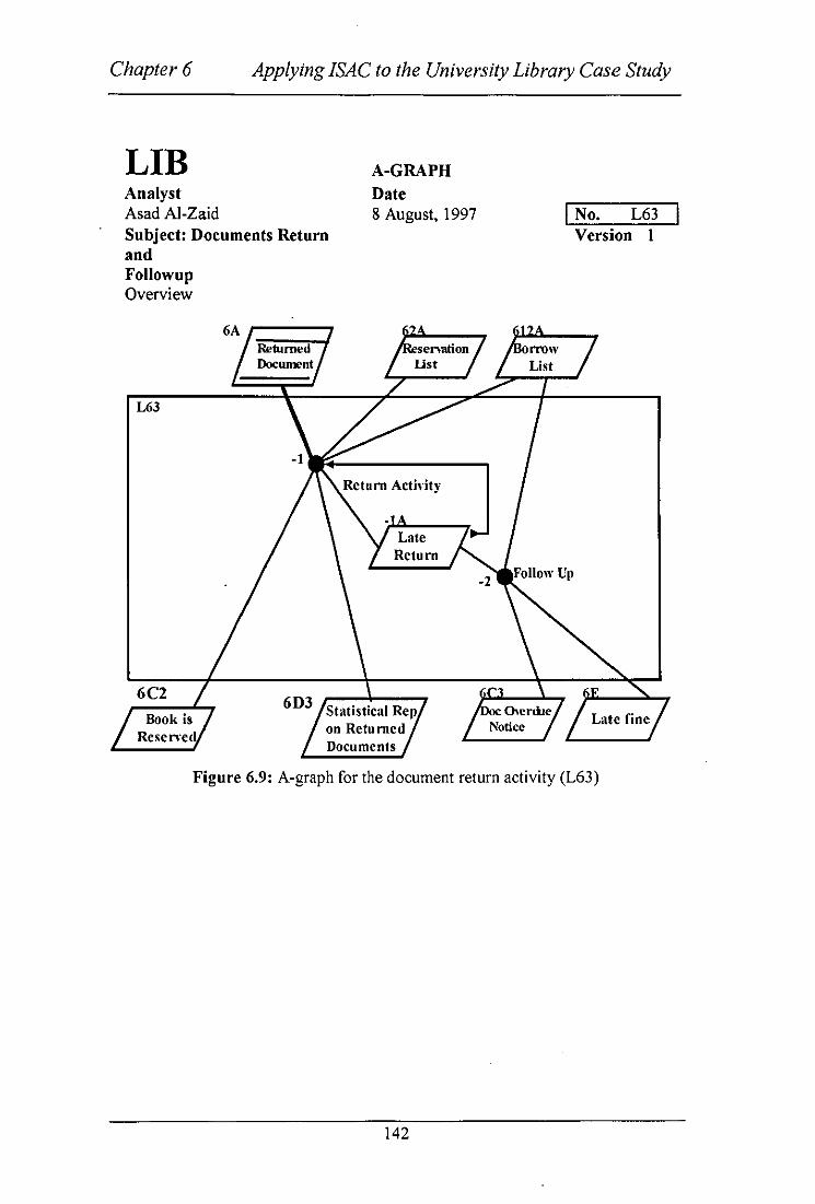
Chapter 6 Applying ISAC to the University Library Case Study
LIB Analyst Asad AI-Zaid Subject: Documents Return and Followup Overview
1.63
A-GRAPH
Date 8 August, 1997
Documents
I No. L63 Version 1
Figure 6.9: A-graph for the document return activity (L63)
142

Chapter 6 Applying ISAC to the University Library Case Study
LIB Analyst Asad AI-Zaid SUbject: Document Return & Followup at Circulation Desk Overview
6A 62A
612A
63
631 631A
632
6E 6C2 6C3
Date
TEXTPAGE A-GRAPH
8 August, 1997
Returned Documents Reservation List Borrow List
Return and Follow Up
Returned Activity Late Return Follow Up
Late Fine Book is Reserved Documents Overdue Notice
Table 6.19: Text page for A-graph L63
143
I No. L63 Version I

Chapter 6 Applying ISAC to the University Library Case Study
Ambition levels
For each system to be automated (such as the circulation desk) a desired
properties should be specified, called ambition levels. In this case study ambition
levels included limits on response time, timeliness of output, volume and
frequency of input, and requirements on the quality of input and output data see
Table 6.19.
Attributes Measure Current High ambition Low
ambition
Response Seconds in Not 2 sec. Avg. per 5 sec. Avg.
time real time applicable day. per day
5sec. Max. 20 sec. Max.
Volume of Total 30 avg. per 200 avg. per day. 50 avg. per
Transaction number per day 60 max. 300 max. day lOO max.
day for
library
Latency of Real time I day avg. I second avg. I sec. Avg.
data between per year per day per day
event Iday max. I hour max. I day max.
occurrence
and
database
transaction
Table 6.20: Table of ambition levels for some system attributes
144

Chapter 6 Applying ISAC to the University Library Case Study
Analysis of contribution. In A-graph L6 in Figure 6.4, the Return activity L63 is
served by the Reservation List (L6ZA). A more detailed description of the
activities in the Return is shown in Figure 6.9 and Table 6.18. The Reservation list
(6ZA) is used by the employees of the circulation desk to check the reserved
documents. The Reservation List is checked before the document is released for
borrowing again.
6.3 Information System
At this stage of the methodology, ISAC uses the precedent and component
analysis. The precedent analysis uses an I-graph (Information precedent graph) in
order to analyse information precedent relations in an information system. The
component analysis uses the C-graph (Component relation graph) to analyse the
structure of the information sets, which involves analysing the message type that
describe the me&sage sets. Comparing ISAC with other methodologies, the ISAC
term for functional analysis is precedent analysis.
The first step to be made at this stage is to decide on the information subsystems
that are going to be analysed. This is documented in the information analysis
planing table, see Table 6.Z0. The subsystems that require a precedent and
component analysis are as follows:
• Borrowing (L6111)
• Renewal (L6IZI)
• Reservation (L6ZI)
• Return (L63 I )
Document borrowing (L6111)
The transition from activity studies is performed in the following steps:
• From the A-graph L61 (Figure 6.5) it follows that the input sets are Borrow
Request, Reservation List and Borrow List updated and the output sets are
145

Chapter 6 Applying ISAC to the University Library Case Study
Get book, Statistical Report on Borrowed Document, and Book is
Reserved.
• The output sets should consist of information concerning whether the
document is borrowed, reserved, or not in the catalogue. This is in addition
to the information concerning whether the book is already borrowed or not.
A statistical report is also issued for all borrowed documents.
• An overview I-graph (BR) is drawn in Figure 6.10 to s~ow the precedent
analysis for the borrow desk.
• The information analysis planning table shows that no continued precedent
analysis is needed.
The component analysis for Document Borrowing activity is performed in the
following steps:
• The Updated Borrow list is subdivided into Member Details, Document
Details and Document Borrowing Report.
• Member Details should consist of Member ID and Member Address.
Document Details should consist of the Document Title and Document
number. Borrow List Report should consist of the date and time of
borrowed documents.
• In Member Details Information, Member is the identification term and
the rest are property terms related to Member. In Document Details the
Information Document is the identification term and the rest are property
terms related to document.
• The result is documented in a C-graph in Figure 6.11.
The component analysis for the Statistical Report on Borrowed information is
performed as follows:
• The Statistical Report is subdivided into Document Details, Report Date,
and Statistical summary report
• Document Details should consist of a document title and document
number.
• Report Date should consist of status messages.
146

Chapter 6 Applying ISAC to the University Library Case Study
• Statistical Summary Report should consist of values such as Number of borrowing.
The rest of the information sets of the borrowing information follow directly in a
similar manner.
Document Renewal List (L6121).
The overview I-graph (ON) for Renewal information is found in Figure 6.13
showing the precedent analysis. The Corresponding C-graph is depicted in Figure
6.14.
• From A-graph L612 (Figure 6.7) it follows that the input sets are "Renew
Request" and "Reservation list" and the output sets are "Renewal
Confirmed" and "Renewal Rejected".
• The output sets should consist of information about weather the document
is renewed or rejected.
• An overview I-graph (ON) is drawn in Figure 6.13 to show the precedent
information analysis.
The C-graph for information set ON6A will have a similar structure as the
previous C-graph constructed for information set (B3A).
Document Reservation (L621).
The overview I-graph (OR) for Oocument Reservation is found in Figure 6.15
showing the precedent information analysis. The corresponding C-graph is
depicted in Figures 6.16 and 6.17.
The overview I-graph (OR) will have a similar structure as (BR) in Figure 6.10
and is therefore not repeated here. Corresponding C-graphs are found in Figures
6.16 and 6.17. The C-graphs will not be explained here because they have a
similar structure as Figures 6.11 and 6.12.
147

Chapter 6 Applying ISAC to the University Library Case Study
Document return (L63).
The overview I-graph (R) for Document Return is found in Figure 6.18 showing
the precedent information analysis. The corresponding C-graph is depicted in
. Figures 6.19 and 6.20.
The overview I-graph (R) will have a similar structure as (BR) in Figure 6.10 and
is therefore not repeated here. Corresponding C-graphs are found in Figures 6.19 . and 6.20. The C-graphs are not explained here because they have a similar
structure as Figures 6.11 and 6.12.
148

Chapter 6 Applying ISAC to the University Library Case Study
LIB Analyst Asad AI-Zaid Subject: Borrow
BR
-3A' ~-----. ,I I I
Updated Borrow List
I -3A ,.-----.
4A
Get Document
(L6116B) (L61l6DI)
I-GRAPH Date 8 August, 1998
JA(L6llJAI)
Borrow Request
(L61l6CI) IL61l6C2)
I No. B Version I
2A(L61162A)
not in Catalo (L6116tllC)
Figure 6.10: The I-graph for the borrow desk
149

Chapter 6 Applying ISAC to the University Library Case Study
LIB Analyst Asad AI-Zaid Subject: Borrow
-11
Member
Member Address
C-GRAPH Date 8 August, 1997
BR3A ~---,
-2 Document
Details
Doe TItle
Doe No.
I No. Version 1
Figure 6.11: The C-graph for updated borrow list (B3A)
150

Chapter 6 Applying ISAC to the University Library Case Study
LIB Analyst Asad Al-Zaid Subject: Statistical Report on Borrowed Documents
Doe Name
Doe No.
C-GRAPH Date 8 August, 1997
Status Message
I No. Version 1
Figure 6.12: The C-graph for the statistical report on borrowing (B5A)
151

Chapter 6 Applying ISAC to the University Library Case Study
LIB Analyst Asad AI-Zaid Subject: Renewal
DN
SA Borrow List
Updated
lA
Renewal Request
I-GRAPH
Date 8 August, 1997
Member Details
Document Details
I No. D
2A
Version I
Reservation List
.J~~------------------~
-3A
Renewal Confirmed
Book is Reserved
Renewal Rejected
Figure 6.13: The I-graph for the renewal desk
152

Chapter 6 Applying ISAC to the University Library Case Study
LIB Analyst Asad AI-Zaid Subject: Renewal
Overview
-11
Customer ID
Member
Customer Address
C-GRAPH Date 8 August, 1997
DN6A
Doe Name
~---.....
Doe No.
I No. Version 1
Figure 6.14: The C-graph for the renewal information (D6A)
153

Chapter 6 Applying ISAC to the University Library Case Study
LIB Analyst Asad AI-Zaid Subject: Reservation
DR -4A'
Document
I-GRAPH Date 8 August, 1997
Al Resen'ation
Request
Resen'ation is Deleted
-4
Member
I No. OR Version 1
A2,..... __ --Y
Borrow List
Figure 6.15: The I-graph for reservation information
154

Chapter 6 Applying [SAC to the University Library Case Study
LIB Analyst Asad AI-Zaid Subject: Reservation
-11
Customer ID
Key: /
Customer Address
Information / Set
C-GRAPH Date 8 August, 1997
Doe Name
Doe NO.
FJementary Information
Set
I No. LO Version 1
Reservation (Date,lime)
Almost Elementary Information Set
Figure 6.16: The C-graph for document reservation (DR4A)
155

Chapter 6 Applying ISAC to the University Library Case Study
LIB Analyst Asad Al-Zayed SUbject: Statistical Report on Reserved Documents.
Doe Name
Doe No.
C-GRAPH Date 8 August, 1997 I No.
Version I
Status Message Date of Reservation
Figure 6.17: The C-graph for statistical report on reservations (DR6A)
156

Chapter 6
LIB Analyst Asad AI-Zayed Subject: Return
R
Applying ISAC to the University Library Case Study
I-GRAPH Date 8 August, 1997
Date E.'pircd
Return Fine
Figure 6.18: The I-graph for the return desk
157
I No. R Version 1
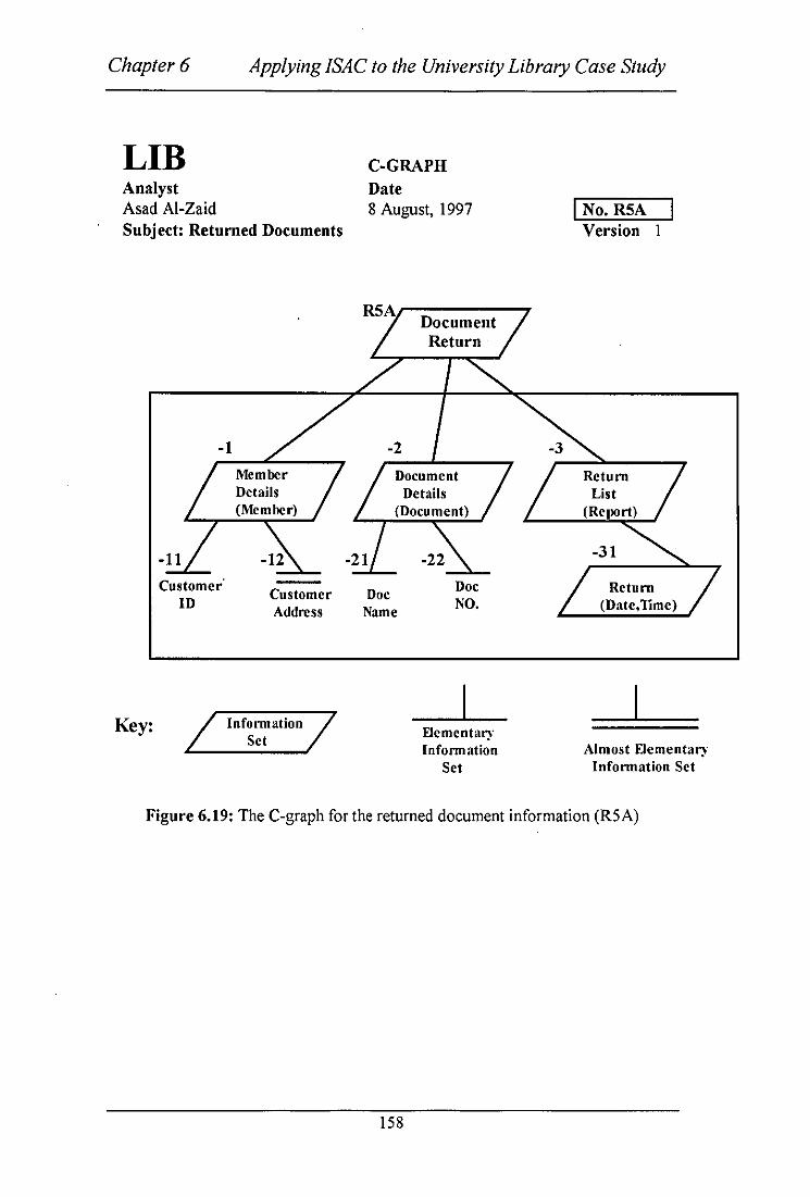
Chapter 6 Applying ISAC to the University Library Case Study
LIB Analyst Asad AI-Zaid SUbject: Returned Documents
Key:
-11
Customer ID
/
Customer Address
Infonnation 7 Set
C-GRAPH Date 8 August, 1997
Doe Name
Doe NO.
Flcmcntary Infonnation
Set
I No. RSA Version 1
Return (Date, Time)
Almost Flementary Infonnation Set
Figure 6.19: The C-graph for the returned document information (R5A)
158

Chapter 6 Applying ISAC to the University Library Case Study
LIB Analyst Asad Al-Zaid Subject: Statistical Report on Reserved Documents
Doe Name
Doe No.
C-GRAPH Date 8 August, 1997
Status Message
I No. R7A Version 1
Number of Returns
Figure 6.20: The C-graph for the statistical report on reserved documents (R 7 A)
159

Chapter 6 Applying ISAC to the University Library Case Study
6.4 Weaknesses and Limitations of the ISAC Methodology
From applying the ISAC methodology to the library case study it was found that
. ISAC has the following weaknesses:
1. The graphical tools used in ISAC generate large volumes of information
graphs supplemented with text pages and property tables (as can be seen in
the Library case study). This can make the developer work out the model in
so much detail that too much time will be lost in modelling a situation that
should be changed.
2. The cross-referencing mechanism that is used in ISAC can be very
cumbersome. The problem with this mechanism is when the methodology
is applied to a large complex system The large amount of information is
overwhelming and causes confusion.
In the libr~ry case study, for example, each graph has it own Text pages
(Figure 6.2). Imagine that after finishing the modelling of the whole system
in the organisation, during the revision process, it was found a necessary to
add a message set, or an input set has to be added to one of the A-graphs
developed at the change analysis stage. To do so would require changing all
the reference numbering in all the following A-graphs in addition to the text
pages and the property tables. This process can take time and effort,
especially when the people who are going to do this process are the users or
problem owners who have no experience with this methodology.
3. When modelling a large system, "at the lower level of modelling, the
activity model may not be understood by problem owners because of its
complexity and too many attachments. Therefore it cannot serve as a means
of communicating about alternative future situations" (Dale, A.G., 1983).
4. The process of decomposition followed in ISAC methodology may
generate many graphs when the project is large and complex. This is due to
the decomposing process of each uctivity in the overview A-graph model
160

Chapter 6 Applying ISAC to the University Library Case Study
(Figure 6.1) into many subactivities until the desired model is reached. This
may amount to 50 or lOO graphs, with each graph supplemented with text
pages. This large amount of information may not be under~tood and can
really create some confusion for the users. Miller, (1956) stated that the
human brain can only handle +7 or - 2 objects in the front of our conscious
(short time memory) at any given time. To demonstrate this, imagine that
we have 4 oranges, 90% of the population will imagine them as a one row of
4 objects, now imagine that we have 8 oranges, 90% of the population will
imagine them as 2 rows of 4 oranges. What happened is our brain imposes a
structure to handle the object complexity. Two rows of 4 oranges are
equivalent of one row of eight, but 2 row of 4 oranges are actually two
groups of 4 objects.
This is how our brain handles the complexity of objects So in relation to our
problem, when we have 50 graphs or more we can ask the question: how can
the human brain handle this complexity? We have this problem because of
the way the human brain deals with complexity. It deals with complexity by
imposing a tree like structure, you can only store so many things and the
bigger that tree gets, the more bits fall off. Also our short time memory can
only remember a few things at a time, therefore by the time we reach the
information-graphs at the lower level, we will have forgotten about the
information-graphs at the beginning of the modelling.
5. When decomposing the A-graph models in the Activity Study stage, there
is no indication of when to stop the decomposition. The methodology
describes this approach as "carry the decomposition process so far that all
problems can be related to some activities or sets in the A-graph or when
basic unsplittable functions are reached".
6. The cross-referencing between sets in A-graph and the same set in I-graph
is achieved by including the A-graph name alongside the I-graph entry, see
Figure 6.10. The problem with this approach is that it creates a multiplicity
161

Chapter 6 Applying ISAC to the University Library Case Study
of names for the same set for no important reason other than creating a
different string name.
7. Property tables are difficult to construct and there are no guidelines for
producing them.
8. Although some people find the methodology easy to use, it needs a high
degree of training in order to use it efficiently, especially when it is used by
people who are new to the system analysis like novice users.
9. In the change analysis stage, the methodology does not create an overview
modelling of the whole organisation like other methodologies. It takes the
approach of modelling each subsystem individually such that changes
proposed for the system cannot be seen for the whole organisation.
10. The ISAC methodology only addresses the technical part of the system and
ignores the social part.
11. The ISAC methodology ignores the organisational issues when designing a
system.
6.5 Strengths Of ISAC Methodology
I. The analysis of problems and user requirements in the Change Analysis
stage is very thorough and well documented. This helps in the process of
determining the problems and identifying the cause of these problems before
starting to model the system. This can be seen through the graphs and tables
developed in the first stage of the methodology. For example, see Figure 6.1
and Table 6.1.
2. One of ISAC advantages is that it creates a close relationship between the
users, or problem owners and system analyst. Users are able to describe and
analyse their own activities where system analyst's role is to give help and
support whenever is needed. This process helps the users to understand their
162

Chapter 6 Applying ISAC to the University Library Case Study
existing problems and to present requirements to the analyst using A-graphs
and tables.
3. Documenting user problems, user requirements (needs) and goals of the
organisation in tables serves to help the communication process between
system analyst and problem owners by providing records of decisions and
agreements. This process is useful when a document is read by someone
without knowledge of system development.
4. Before modelling the new system the ISAC methodology produces a
number of possible solutions (change alternatives) allowing the problem
owner to decide on the most appropriate solution for the organisation.
6.6 Concluding Remarks
The ISAC methodology has been applied to the University library case study to
show its strengths and weaknesses. Using the library case study it was possible to
test all the graphical tools and notations that are used within the ISAC
methodology. The first stage of the methodology was used to identify the business
problems of the library organisation, the problem owners that are associated with
these problems, the change needs and the change alternatives. The advantages of
this stage are firstly, the problems of the library are well investigated and
documented, secondly, the business needs of the library are identified, and thirdly,
the Library objectives are identified. The second stage, which is the activity study,
models the future system to the library. The ISAC methodology tries to model
each information subsystem on its own that is why a separate A-graph is
constructed for the borrowing, reservation, and returning systems. The
information system stage shows the functional decomposition of the library
system using the I-graphs and C-graphs. In the equipment adoption stage the
problem owners choose the appropriate hardware and software for the new library
system.
163

Chapter 7 A Critical Evaluation of ISAC and ORDIT Methodologies
Chapter 7
7.0 Introduction
A Critical Evaluation ojISACandORDIT Methodologies
The evaluation criteria presented in this chapter have been developed through the
analysis work that has been done earlier in chapters 4 and 6. In chapter 4, the use
of ORDIT methodology its tools, strength and limitations are explained. In the
same manner the use of ISAC methodology its activity model, its strengths and
limitations have been explained in chapter 6. All this analysis is backed up by
applying the library case study to both methodologies. In this chapter a table is
constructed wit~ a list of factors to evaluate ORDIT and ISAC methodologies
against organisational needs, user needs, business needs and socio-technical
needs. This evaluation criterion will provide a set of results, which will be used in
the combined methodology that will be presented in the next chapter.
7.1 Rational for Choosing Factors to the New Methodology.
The most important aspect of user-oriented design is the realisation that the users
and their needs are the only reason for the existence of the project. Elegant and
powerful information systems may be desirable, but if they do not satisfy the
client's needs and/or they are hard to operate, then they are rejected by their users
even if they are technically sound. Literature (Eason, 1988) has proven that in
order to have a system that is fit for its purpose, developers must communicate
with users in their own language and users have to be involved in the development
process.
In addition to user involvement, literature (Doherty, N., et aI, 1997) proves that
organisational issues are essential to the success of system development. In the
164

Chapter 7 A Critical Evaluation of ISAC and ORDIT Methodologies
past, many systems designers have solved the problems of the enterprise in the
way they see it without consulting or communicating with the users. This created
problems for the users where the system developed is technically sound but the
users could not deal with it because it did not support the human being in
facilitating or improving their activities.
Hornby, P. et ai, (1992) stated that 'lack of attention to organisational and human
issues, it is proposed, is a major contributory factor in the underperformance ofIT
systems'. He also found that coverage of human and organisational issues in most
of the existing system development methods is patchy in the mainstream technical
methods, and although users have some participation where they can provide
information, their role in the method is often unclear.
Ewuis-Mensah and Przasnyski (1994), also stated that "organisational issues are
the most widespread and dominant factor" when it comes to the factors
contributing to the abandonment of systems development project. Lyytinen, K. et
al. (1991), stated that there is a growing realisation that it is often organisational
issues that play a substantial, if not primary, role in system failure. An interesting
example of this was the failure of the London Ambulance Service (LAS)' s
Computer Aided Dispatch system (LAS, 1993). One of the primary criticisms of
the formal inquiry into the failure of the Computer Aided Dispatch system was
that the management of the London Ambulance Service had expected that the
implementation of the system would automatically bring about changes to the
working practices of staff, rather than explicitly reviewing and planning for its
organisational impact.
The importance of the socio-technical system approach is to produce technical and
social structures which have a high capacity to achieve technical and social goals
and which enforce each other in the achievement of these goals. Mumford, (1983)
defined the socio-technical approach as a design philosophy that produces
productivity, quality, co-ordination and control; but also provides a work
environment and task structure in which people can achieve personal development
and satisfaction. When developing an information system, social issues (soft
165

Chapter 7 A Critical Evaluation of ISAC and ORDIT Methodologies
systems) should be given the same amount of attention as the technical issues
(hard systems). This is to support the way in which the human components of the
work system are organised. London Ambulance Service (LAS, 1993) is one of
. the examples which proved that concentrating on technical issues only can
contribute to system failure. In this example, members of the organisation reacted
against the despatch system where the technical solution made it very difficult for
staff to undertake their dutie.s effectively, with the result that patients waited many
hours for an ambulance. Eason (1988) and Clegg et al (1989b) identified the
following factors as contributing to system failure:
• Lack of end-user participation and end-user 'ownership' of systems;
• Lack of attention to education, training and awareness;
• Lack of guiding organisational and business strategies (as opposed to
technical strategies);
• Lack of organisational resources and support (concerning the' soft'
infrastructure);
• Lack of attention to organisational issues such as organisational design,
organisational structure, management style; and
• Lack of attention to psychological issues such as the design of jobs, the
allocation of systems tasks, and the usability of the system.
Combining the first and second of these factors and also the fourth and fifth, gives
four factors which will be used in the new methodology. These four factors are
-User needs and participation,
-Organisational issues and needs,
-Business needs
-Socio-technical needs.
It is believed that in order for the new methodology to be able to solve the main
problem explained in chapter one, it has to include the above four factors
otherwise the methodology will produce systems that will fail.
In this chapter ORDIT and ISAC methodologies are evaluated against these four
factors.
166

Chapter 7 A Critical Evaluation of ISAC and ORDIT Methodologies
7.2 The Four Essential Factors for the New Methodology
For the purpose of comparing the strengths and weaknesses of ORDIT and ISAC
methodologies. The four main factors that were mentioned in section 7.1 (with
their sub-factors) are going to be analysed represented and used in this chapter in
order to guide the design and implementation of IT systems in the organisations
within the new developed methodology.
7.2.1 User Needs
User needs include the following sub-factors:
• Stakeholder information, such as name, job title, department, and name of
supervisor, name of subordinates, activities and resources;
• Current attitudes to IT including fears and hopes;
• User's job needs, including performing a task effectively, having the right
skill level agreeable to the user, and social interaction.
7.2.2 Organisational Needs
Organisational issues needs include the following sub-factors:
• Current work pattern: e.g. agents, activities, resources, information flow,
role, responsibilities and mutual obligation;
• Infrastructure support for IT, e.g. defining systems used or currently in use,
computing skills/experience, and history of IT introduction;
• Problem identification
• Pre-implementation impact analysis;
• Organisational issues analysis, e.g. organisational structure, authority
relations, personnel, training, politics and power.
7.2.3 Business Needs
Business needs include the following sub-factors:
• Business strategy and objectives;
• IT strategy;
• Business mission.
167

Chapter 7 A Critical Evaluation of ISAC and ORDIT Methodologies
7.2.4 Socio-Technical Needs
Socio-technical needs include the following sub-factors:
• Conventional technical needs analysis
• Socio-technical needs analysis
7.3 The Evaluation Criteria
7.3.1 Stakeholders' Information: These are name, job, title, department,
name of immediate manager, names of subordinates, activities, resources,
and supervisor.
ISAC:
The ISAC methodology identifies the stakeholders involved in the organisation as
some of the problem owners that have a stake in the new system, for example,
Librarian, Treasurer, and Circulation Desk in Table 7.1. The process of
identification is carried out in the change analysis stage through identifying the
problems against the problem owners.
Problem Owners Problems Activities in A-2raph
Faculties P5 C4 Librarv Member PI, P2, P3 C6
Librarian Pt, P2, P4,P5 C6 Treasurer PI, P4, P5 C4, C5,C6
Circulation Desk PI, P2, P3 C6
Table 7.1: Initial matrix of problems against problem owners
ORDIT:
When the ORDIT methodology was applied to the library case study (Figure 7.1),
the stakeholders outside and inside the Library organisation were identified; as
was their roles within the Library organisation. At a later stage, the responsibilities
that these stakeholders have towards the system within the organisation were
identified as well.
168

Chapter 7 A Critical Evaluation of ISAC and ORDIT Methodologies
The above analysis shows that both methodologies identify stakeholders in
different ways. ISAC identifies the stakeholders by listing them in a table of
problem owners against the problems that they have with the current system.
ORDIT, on the other hand, draws a box around the organisation to identify the
stakeholders inside and outside the organisation in order to identifY who is
involved in the system and who is not.
The table of problems against problem owners taken from ISAC is preferred
because it is easier to understand and straightforward to use.
University Library
Administration
Librarian Library Members
Circulation Desk Faculties
Book Publisher Treasurer
Journal Publishers
Figure 7.1: External and internal agencies that have an effect on the Library system
7.3.2 Attitude to IT: Fears and hopes of the users.
ISAC
The methodology advocates the participation process through the first and second
stages only. This process helps the problem solver to identify the user attitude
through the development process. ISAC deals with user attitude by considering
that different people within the same problem owners group react differently to
IT, therefore the developers must make sure that an agreement has been reached
before they can take any further action. Although, the ISAC methodology
identifies that there are people who work against the new system and others who
169

Chapter 7 A Critical Evaluation of ISAC and ORDlT Methodologies
work towards it, it does not mention how to deal with the users' attitudes or
reactions against the new system when it occurs.
ORDIT
The ORDIT methodology advocates the participation process as well through all
stages. This process as mentioned above helps the problem solver to identify user
attitude through the development process. The ORDIT metho~ology does not
mention any thing about how to deal with the user fears and hopes in all it stages.
The analysis above shows that the ISAC methodology deals only partially with the
user attitude problem. However, ORDIT does not support this issue at all.
7.3.3 User job needs. This includes the following elements: "Needs to
perform tasks effectively, to have the right skill level agreeable to the user,
to have the right level of control of his/her work, to desirable tasks, to have
job satisfaction, not to be afraid oflosing his/her job because of the new
system being introduced, and need for social interaction." (Woherem, 1991
and Wo here m, 1994).
[SAC
The methodology does not mention how the change needs will effect the user's
tasks or whether the user is going to be satisfied with the new job or not. The
ISAC methodology does not mention anything about job design or job
satisfaction.
ORDIT
The ORDIT methodology, on the other hand, looks at the user job needs through
its role-relation model diagram (Figure 7.2). The role-relation model describes
what the role holder has to do and whether he has been allocated the capability
tokens needed to discharge the obligation imposed on him by his responsibility.
The obligation describes the "job" and the link between responsibilities and
activities executed. For example, in the library case study (Figure 7.2) the
treasurer has the responsibility of providing the right amount of money for book
170

•
Chapter 7 A Critical Evaluation of ISAC and ORDIT Methodologies
'publishers and other issues, To fulfil his responsibility, for example, he has to
perform different activities such as notifying library departments about their
budget limit, make sure they do not exceed that limit, and pay publishers for new
books,
The above analysis shows that ISAC has no support for this subfactor. On the
other hand, ORDIT applies the socio-technical approach where human
consideration such as job satisfaction, and task definition, are considered, This
approach makes ORDIT a better methodology than ISAC in identifying the users'
jobs needs and the information or resources needed in order to do their jobs
correctly,
Send Do c to Lib
Publisher Treasurer
( Provider Consume~
Send Invoice Pay Invoice
I\ccept Doc Inf
Provider J I (Consumer
Structural Relationship
Functional Relationship
Figure 7.2: Role relationship diagram
Librarian
end Doc Info
Provider)
7.3.4 Current Work Pattern e.g.: agents, activities, resources, information
flow, roles, responsibilities and mutual obligation.
ISAC
The A-graph in Figure 7.4 shows the model of the current work activities in the
library system. It shows the functional relationship, the information flow among
them, and the resources and material (dark lines) that are involved in those
activities. However, the activity model dose not define the roles and
responsibilities for the agents in the Library.
171

Chapter 7 A Critical Evaluation of ISAC and ORDIT Methodologies
ORmT
Using the responsibility model, ORDIT methodology models the current situation
in the organisation showing the main agents and their responsibilities (Figure 7.5).
The responsibility relationships of the outside agencies to the organisation are
identified and the distributions of responsibilities held by agencies within the
organisation are explored. The organisation is considered as a single agency and
then decomposed into the agencies it encapsulates. For example, Figure 7.3.
shows the responsibility of the Circulation Desk towards the Member agent and
the lists of obligations and activities that have to be discharged in order to fulfil
the responsibilities imposed on them.
The above analysis shows that ORDIT methodology uses the socio-technical
approach, which is a better way than ISAC to describe the current work pattern in
an organisation. Through the responsibility model ORDIT is able to define the
functional and structural relationships of the organisation which gives a clearer
picture of the responsibilities held by agents in the organisation, their obligations,
and their roles. ISAC, on the other hand, uses the activity model to identify only
the functional dependency between agencies. This is considered one of the
drawbacks of ISAC as explained in the previous section.
Circlllation Desk Responsibility for: Adeqllacy of sen'ices prOl·ided for members.
Obligations:
To provide a library pass for members in order to use the library
To provide the borrowing service
To provide the reservation service
To provide the return document service
To put on shelf returned documents and make them available for members
To register all document activities.
172

Chapter 7 A Critical Evaluation of ISAC and ORDIT Methodologies
Activities:
To take member information
To take document information
To make document reservation for member
To make borrowing services for member
Take returned document from member
To check returned document date
To update returned document records
To update member record
Figure 7.3: List of obligation and activities for the Circulation desk
7.3.5 Infrastructure Support for IT
Both methodologies have no support for this subfactor. Neither ISAC nor ORDIT
emphasise that a study has to be done on the history ofIT in the organisation in
order to evaluate the current system and find out which parts of the system can be
used with the new system and which parts become obsolete.
7.3.6 Problem Identification
ISAC
This is one of the strongest parts in the ISAC methodology where problems are
identified and listed in a table and then analysed before modelling of the new
system starts. In the change analysis stage, problems are listed in the problem
table, as seen in the library case study. These problems are ana!ysed in order to
identify new problems that are mentioned by problem owners. Then the problems
are reduced to a manageable numbers by eliminating problems that are:
• Too easy to solve
• Too difficult to solve
173

Chapter 7 A Critical Evaluation of ISAC and ORDIT Methodologies
• Not relevant (e.g. Dollar fluctuation in the library case study)
ORDIT
Problems are elicited from problem owners in order to reach agreement about how
. the system should be rather than how it is, and to identify defects in the current
system and how these might be overcome. Statements of requirements are then
classified in order to identify conflicts, particularly conflict in definitions of
boundary objects and organisational aspects.
The nature of the problem to be solved is identified. The development team has to
get the agreement of the client on the problem to be solved so that the modelling
has to focus on the chosen issue. This is done to reduce the problems identified to
a manageable number, since the system model is restricted to only what is relevant
to that perspective.
As stated in the analysis above, Problem Identification is one of the strongest parts
in the ISAC methodology. The methodology is in agreement with the idea that
too often problems are ignored by the system analyst in the rush to computerise
but, you cannot solve a problem until you know what the problem is. Most of the
work in the ISAC change analysis is devoted to understanding the problem.
Therefore the problem identification process in ISAC is performed better than
OROIT. Although ORDIT defines the problems in the organisation, there is no
sign of documenting them as part of the methodology.
174

Chapter 7 A Critical Evaluation of ISAC and ORDIT Methodologies
Figure 7.4: Circulation Desk A-graph in the Library case study
7.3.7 Pre-implementation Impact Analysis
Both methodologies enable us to explore the impact of the new changes on the
current system because both of them generate future alternatives in order to let us
look at how the system will change in the future. However, none of the two
methodologies emphasise that the impact of changes to the new system must be
analysed before implementation.
7.3.8 Organisational Issues Analysis: These are authoring relation, politics,
personal characteristics and organisational structure.
ISAC methodology does not support the organisational factors
OROIT
One of the central concepts in the OROIT methodology is the structural
relationship that describes the relationship between agents in the organisation
(Figure 7.5). This relationship can describe the structure of the organisation and its
175

Chapter 7 A Critical Evaluation of ISAC and ORDIT Methodologies
policy. This is one of the strongest parts of the responsibility model when applied
to an organisation. The responsibility model is a high level abstract model, it
considers all responsibilities that different agents have towards each other for a
. state of affairs and the rights they have to any information that needs to be used.
Often at this stage of representation the responsibility that the organisation may
possess as a whole is considered along with the relationship between the
organisation and outside parties, which describes the policy of the organisation
(Figure 7.5). In addition, the structural relationship can embody the organisational
structure in terms of authorisation and power, and generate requirements in terms
of information and communication structures on any IT system that installed.
To give an example, illustrated in Figure 7.5, the policy of the library is depicted
through the structural relationships with the outside agencies. This policy is to
provide services to the members of the library and provide the library with the
required documents to be consumed.
The analysis above shows that Organisation factors analysis is one of the strongest
parts of the ORDIT methodology where the structure and policy of the
organisation are identified. This is done through the responsibility model, as
identifying the functional and structural relationships in the organisation. The
activity model used in the ISAC methodology only supports the functional
relationship between agencies and ignores the structural relationship which makes
it unable to support some of the essential parts of the organisational factor analysis
like job satisfaction, organisational structure and the policy of the organisation.
176

Chapter 7 A Critical Evaluation ojISAC and ORDIT Methodologies
Member
Request Service·
( Client '\
Publisher
Provide Documents
( Supplier '\
University Library
Provide Services
Server )
Purchase Documents
Structural Relationships
Functional Relationships
Customer)
Figure 7.5: Top Responsibility Model
7.3.9 Business Strategy and Objectives:
ISAC
Through its goal analysis process, ISAC tries to identify the business strategy for
the organisation by identifying the business objectives that the new information
system should provide for the organisation.
One of the valuable techniques in ISAC methodology is the goal trace process,
where each goal is traced to see why it has not been achieved. This is done by
listing all the problems, which prevent that goal from being achieved. By doing
this, the change needs can be identified and these will act as an objective of the
development process and the business strategy for the organisation.
DROIT
ORDrr on the other hand involves the discussion of the future alternatives with
problem owners until the desired situation (goal) is reached. However, ISAC
takes it a step further by analysing those goals until the business strategy or
mission for the organisation is specified.
177

Chapter 7 A Critical Evaluation of ISAC and ORDIT Methodologies
Needs Description Problems Objectives
NI Return procedure should be P2,P3,P8, PII 01,03 improved so that document is available and the service to the customers are maximised
NZ Acquisition should be PS, P6, P7 02 coordinated so that mUltiple , acquisitions are reduced
N3 Statistics should be improved P4 04
N4 The possibility of theft should PlO 01 be reduced
Table 7.2: Table of change needs
7.3.10 IT Strategy; Compare IT cost with business plan, To Increase
productivity and performance.
Neither methodology has support for this subfactor. Neither of the two
methodologies supports evaluating the cost of the hardware or the software that is
needed to implement the new system successfully. Neither of the two
methodologies supports the alignment ofIT strategy with the business goals or
objectives.
7.3.11 Business Mission: Identifying the business goals and objectives as
well as the desired situation for the organisation.
ISAC
In the change analysis stage, ISAC tries to investigate the desired situation for the
organisation by identifying the business goals and objectives that the new
information system should provide for the organisation. The business mission is
the highest level goal of the business. The desired situations are listed in a table of
goals against the current problems, and objectives. Then the goals are negotiated
178

Chapter 7 A Critical Evaluation of ISAC and ORDIT Methodologies
with problem owners to avoid contradictory situations. An example of the list of
goals (desired situation) is given in Table 7.2.
ORDIT
The ORDIT methodology does not support or represent the business mission of an organisation.
7.3.12 Conventional Technical Needs Analysis: Concerns the technical
functionality requirement that has to do with tasks and how it should
be performed.
ISAC
ISAC uses the A-graph model in order to model the activities in the organisation.
It also uses the activity model in order to analyse the functional requirements of
the system and to show the processes performed on inputs to produce outputs.
Therefore the ISAC methodology supports the conventional technical system.
ORDIT
ORDIT methodology does not support the conventional technical system. It only
has support for the socio-technical approach.
7.3.13 Socio-Technical Needs: All social and technical aspects of the system
should be brought together in order to produce a socio-technical
system.
ISAC
Although ISAC methodology does not support the socio-technical approach as
explained in section 7.3.12, it does have some social parts to it, which is illustrated
in the process of user participation. The methodology lacks important factors of
support such as organisational structure, job satisfaction, and organisational
requirements.
179

Chapter 7 A Critical Evaluation of ISAC and ORDIT Methodologies
ORDIT
The ORDIT methodology supports the socio-technical approach where the human
considerations such as job satisfaction, task definition and so on, are just as
important as technical considerations.
7.4 Evaluation Criteria framework
NEEDS ORDIT ISAC USER NEEDS I IIII I I I I I I I IIIIIII IIIIIIIIII III I I I I I I I I I I I III I I I I I I I I I I I I 1///
1- Stakeholder information Support analysis and Support analysis and representation representation
2- Current attitudes to IT ---- Partially support 3- User's iob needs Support analvsis ----ORGANISATIONAL NEEDS III I I I IIIIIIIIII IIII IIII IIIIIIII I I I I I I I I I I IIII III IIIIIII I I IIII 1- Current work patterns Support analysis and Support analysis and
representation representation 2- Infrastructure support for IT ---- ----3- Problems identification Supports analysis and Support analysis and
representation representation 4- Pre-implementation Impact
anal vs is ---- ----5- Organisational issues analysis Support analysis and
reoresentation ----BUSINESS NEEDS I I I I I I I I I I I I I I I I I I I I 1///1 I I I IIII I I I I I I I I I I IIII I I I I I I 1////// I II 1- Business strategy and Recognises needs to
obiectives ---- capture 2. IT strateg'i ---- ----3- Business mission Support analysis and
---- representation SOCIO-TECHNICAL NEEDS IIIIII IIIIIIIIIIII IIIIIIII IIIIII I I I I I I I I I I IIII I I I I I IIII I I I I I II I-Con'ientional technical needs Support analysis and
analvsis ---- representation 2-Socio-technical needs analysis Support analysis and Partially support
representation
Table 7.3: Evaluation criteria framework for comparing ORDIT and ISAC against the four factors
Table 7.3 is a framework for comparing the two methods against the four factors.
It shows that neither of the two methods is strong in the four major areas to which
attention should be paid when constructing the new methodology. The blank
boxes in the framework show that the methodology has no support for that factor.
180

Chapter 7 A Critical Evaluation of ISAC and ORDIT Methodologies
Looking at the framework, it is realised that ORDIT allows stakeholder
information analysis and user job needs and analysis, but offers no support for
attitudes to IT. On the other hand, ISAC supports the stakeholder information,
partially supports user attitude to IT and has no support for user job needs.
In the area of organisational needs analysis, ORDIT is the one that covers almost
all the major issues t~at need to be considered, namely: current work patterns
analysis; problem identification; and organisational needs and analysis. However,
it offers no support for IT infrastructure and pre-implementation impact analysis.
In the area of business needs, ORDIT has no support for any subfactor. ISAC
analyses the current work patterns and has a very strong approach in identifying
problems, but it offers no support for IT infrastructure analysis or pre
implementation impact analysis. In the area of business needs ISAC has the
greatest coverage. It recognises the needs to capture business objectives, business
strategy and business mission. ORDIT on the other hand, has no support for any
of the subfactors in this area. The ISAC method offers support for representing
conventional technical needs for systems to be developed. However ORDIT
offers support for socio-technical needs.
7.5 ISAC Limitations and Strengths of the Four Factors.
The framework in Table 7.3 shows that the ISAC methodology can not support these sub-factors:
• User job needs
• Infrastructure support for IT
• Pre-implementation impact analysis
• Organisational issues analysis
• IT Strategy
181

Chapter 7 A Critical Evaluation of ISAC and ORDlT Methodologies
Also from the analysis above it is shown that when the ISAC methodology is applied the following problems can be solved:
• Stakeholder information
• Partial support for attitude to IT
• Current work pattern
• Problems identification
• Business strategy and objectives
• Business mission
• Conventional technical needs analysis
7.6 ORDIT Limitations and Strengths of the Four Factors.
The framework in Table 7.3 shows that the ORDIT methodology has its limitations in the following sub-factors:
• Attitude to IT
• Infrastructure support for IT
• Pre-implementation impact analysis
• Business strategy and objectives
• Business mission
• IT Strategy
Also from the analysis above it is shown that when the ORDIT is applied the following problems can be solved:
• Stakeholders information
• lTser job needs
• Current work pattern
• Problem identifications
• Organisational issues analysis
• Socio-technical approach
182

Chapter 7 A Critical Evaluation of ISAC and ORDIT Methodologies
7.7 Why Use the Responsibility Model
An objective of the new methodology is to support most of the above factors and
its sub-factors. The activity model used in ISAC methodology is insufficient to
understand and resolve the problems of organisational issues, user satisfaction and
organisational goals. It was decided to adopt the responsibility model for the new
methodology instead of the activity model for the following reasons:
1. Using the responsibility model in the new methodology, it is possible to
define the organisational structure through the structural relationship between
agents. The structural relationship defines the value and nature of the
relationship between agents. For example, the peer to peer relationship
between two agents tell us that there is no power of one over the other and
these two agents have to work together and negotiate in order to reach a
decision. Figure 4.5 has an example of this relationship.
On the other ~and, the activity model used in the ISAC methodology does not
allow us to define the nature of the relationship between agents. For example,
Figure 6.1 is insufficient for exploring the nature of the relationship between
the borrowing and reservation agents.
2. Using the responsibility model it is possible to define the policy of the
organisation through the structural relationships between agents. This point is
analysed in section 7.3.8.
3. Using the responsibility model it is possible to identify requirements at
different levels of the organisation. At the agency level which is a very high
level in the organisation the requirement is to do with policies; at an individual
level the requirement is to do with making work easier. At the intermediary
level, which is the role level, requirements are to do with how the organisation
itself functions and what obligations and capability tokens are necessary to
support this.
On the other hand, the activity model used in ISAC methodology is insufficient
for defining the organisational requirement at different levels. In ISAC
183

Chapter 7 A Critical Evaluation ofISAC and ORDIT Methodologies
methodology the process of capturing the requirement ends before the design
stage. Therefore the modelling techniques in the design stage do not need to
capture the requirement because the process has taken place earlier.
4. Using the responsibility model helps in providing an overview of the
stakeholders' role without initially going into a tremendous level of detail, this
is missing from ISAC methodology. Figure 4.4 defines all the stakeholders'
roles that will be affected by introducing the new system to the university
library. For example, the role of the publisher is to provide new books for the
library, the role of the library is to provide books to educate members and so
on. The benefit of this process is to provide the analyst with an overall clearer
picture so that he/she can give a better representation of what is going on at a
higher level.
The A-graph illustrated in Figure 6.3 defines some of the stakeholders but does
not address their roles within the organisation. It only defines the activities that
each stakeholder has to perform.
7.8 Concluding Remarks
The evaluation criteria used in this chapter are based on four factors as follows:
User needs and participation; organisational issues and needs; Business needs; and
Socio-technical approaches.
ISAC and ORDIT methodologies have been evaluated against the four factors in
order to show their strength and weaknesses. The evaluation shows that ORDIT
and ISAC methodologies only address some of the four factors and neither of
them addresses all the factors. The use of the responsibility modelling for the new
methodology is adopted in order to address most of the organisational issues and
needs. In addition, the responsibility modelling can be used as a tool for
identifying and eliciting requirements when modelling an organisation.
184

Chapter 8
Chapter 8
8.0 Introduction
The New Methodology
The New Methodology
As mentioned in the previous chapters the new methodology is taken from the
combination of ISAC and ORDIT methodologies. The reason for that is to build
on the successful parts of these two methodologies, and develop a methodology
that can offer more advantages to the process of requirement elicitation in the
information system development field than either the ORDIT or ISAC
methodologies. The most important advantages that should be offered are:
• Users and organisational requirements are captured and elicited
• The business problems and strategy of an organisation can be determined;
• An equal attention to both social and technical issues is given when
designing an information system;
• Easy tools that can be understood by different levels of problem owners.
The method used to determine requirements should allow the problem solvers to
explore possible solutions (involving both the IT system and possible
organisational change) and their consequences at the same time as specifying the
problem, thereby refining the understanding of the problem and developing the
solution by an iterative process. (Harker, et, al. 1990).
Most of the information system development methods that adopt the socio
technical approach in their system design do not include the business strategy in
their methodologies. Noble, F. (1991), stated that "socio-technical design was
originally developed for limited shop floor systems, and historically did not
encompass questions of business strategy". Therefore, one of the aims of the new
185

Chapter 8 The New Methodology
methodology is to incorporate these two elements (socio-technical and business
strategy) in one method. Each step in the new methodology is described in more
detail in the following sections.
8.1 The New Methodology
Before starting to explain the new methodology, it should be emphasised in this
chapter, that despite describing the new methodology in a linear sequence, this is
not necessarily how it would actually be approached. The new method supports
and adopts the iterative approach (see Figure 8.1) therefore, it is possible to visit
different stages at different times when modelling the IT system.
Change Analysis ~ ~
System Model .. -Socio-technical -
Design +-
Implementation -f--
Figure 8.1:The iterative process within the new methodology
186

ChapterS The New Methodology
The iteration process in the new methodology takes place in two forms, 1) within
the stage it self, and 2) between different stages.
Iteration within the stage itself
The process of iteration happens within the same stage when we have to go back
and forth between the steps of the stage itself. For example, in the second stage of
the methodology, the process of requirements determination requires several
repeated attempts, which refine the requirements obtained by analysing them and
then checking them with the users, until a satisfactory requirements specification
is obtained.
Iteration between phases
The process of iteration happens between the four stages of the new methodology
as shown in Figure 8.1. For example, an overlooked process may not become
evident until the system modelling stage, so it is better to go back to requirements
determination to redo the requirement model in the first stage. Another example is
when early non-functional requirements concerning system performance in stage
three are found to be impossible, and it is not until physical design or testing (in
stage four) that this is realised.
First Stage
8.2 Change Analysis
8.2.1 Identify the Project Plan
The purpose of this first step is to ensure that the business mission of the
organisation is identified and the problems of the current system are diagnosed
correctly. This process can be accomplished by meeting with the sponsors of the
development process.
187

Chapter 8 The New Methodology
8.2.1.1 Identify the business mission and problems with current systems
through an initial meeting with sponsor.
The first stage of the new methodology starts by meeting with the problem owners
and sponsors of the development process to identify the business mission of the
organisation. DlIring this meeting it is essential to reach an agreement among.
problem owners, developers and sponsors of the development process on what are
the problems of the current system that prevent the business mission from being
achieved.
8.2.1.2 Issue a list of problems identified
Another meeting has to be held without the sponsors in order to discuss the
current system with problem owners. The purpose of this meeting is to find out if
they have further problems to be identified. These problems are written down in a
list of problems so that the problem owners can examine them and discuss them
with the problem solver. An example of the list of problems for the professional
association agency is depicted below in Table 8.1.
Problems Description
NO. Name
PI Workload at peak times of the Examination produced major peaks of year was becoming too work. These peaks require all of the demanding. full time staff plus temporary help.
P2 Membership was growing This gro~ing puts increasing strain on
rapidly. the workload.
P3 The number of examinations This growing puts increasing strain on
was increasing. the workload.
Table 8.1: List of Idenlified problems
Each of these problems in one way or another prevents the professional
association from fulfilling its mission satisfactorily. Each problem in the initial
list of problems is now screened to determine whether it is worth devoting a
development process to solve it. There are two reasons why a problem is removed
from the list. One reason is that the problem is so easy to solve that it is not worth
the trouble of setting up a development project to solve it. The other reason is that
188

Chapter 8 The New Methodology
a problem is so hard to solve that a development project cannot solve it. The
reason for listing these problems first and then eliminating them is that this gives a
chance for the problem owners to become aware of these problems, talk about
them, and reach an agreement that, at least in this development project, they
should ignore them.
8.2.1.3 List groups of people or agencies that are affected by the
problems identified.
Now it is possible to determine the groups of people for whom these problems
exist. Representative from each of these groups should participate in the Change
Analysis stage. Example of groups of problem owners is:
• Senior management
• Education secretary
• Treasurer
• Association secretary
8.2.1.4 Develop a matrix of the problems to be solved VS problem
owners.
In order to get a clear understanding of the situation a matrix of problems against
problem owners is developed and distributed among problem owners in order to
be filled out by them. This is illustrated in the matrix of Table 8.2. This matrix is
filled out by the problem owners themselves with help from the developer if
required.
189

Chapter 8 The New Methodology
Problems Problem Owners
PI Senior manager
PI,P2,P3 Education secretary
P2,P3 Treasurer
Table 8.2: Problem agamst problem owners
8.2.2 Make A Quantitative Study for Each Problem Identified.
The problems identified so far are now subject to a cause-effect analysis.
8.2.2.1 Perform a cause-effect analysis for each problem
The first thing these groups have to do is the cause-effect analysis for the
problems that have been identified. This group had to have a domain specialist
who had expert knowledge of the problems under study such as the end user of the
required system, the sponsor, an outside specialist, and a manager, etc. The
purpose of doing the problem analysis is to eliminate solution-oriented problems
(people tend to explain problems in terms of their solutions) as much as possible
and get to the underlying problems. This makes room for alternative solutions.
Secondly, problem analysis is another way of reducing the problem list in size, in
addition to the elimination of easy and hard problems. Problem analysis allows us
to limit ourselves exclusively to the underlying problems. Thirdly, problem
analysis helps us prepare an effective action, because the rest of the change
analysis can then concentrate on the underlying causes and ignore derived
problems. An example of a cause effect graph is presented in figure 8.1 which is
a direct graph in which nodes represent problems and arrows point from cause to
effect.
190

ChapterS The New Methodology
Figure 8.2: Cause-effect graph of a Professional Association
191

Chapter 8 The New Methodology
8.2.2.2 Conduct a session with problem owners to discuss and approve
updated problems.
In this session the problems that are added or deleted from the list are discussed
with the problems owners in order to finalise the list of problems. The problem list
is updated accordingly as is depicted in the following table 8.3.
Updated Problems Description
No. Name
PI Workload at peak times of Examination produced major peaks of the year was becoming too work. These peaks require all of the demanding. full time staff plus temporary help.
P2 Membership was growing This growing puts increasing strain on
rapidly. the workload.
P3 The number of This growing puts increasing strain on
examinations was the workload.
increasing.
P4 Small number of staff There is not enough staff to handle the
increasing amount of work.
PS Budget overspent To the increase of workload, large
amounts of resources are overspent.
Table 8.3: Example of LIst of updated problems
8.2.2.3 Produce a matrix of the updated problems VS problem owners.
The matrix of the problems against problem owners in table 8.4 is also updated
and reconstructed.
192

Chapter 8 The New Methodology
Problems Problem OwneI s
PI,P4 Senior manager
PI,P2,P3 Education secretary
P2,P3,P5 Treasurer
Table 8.4: Example of updated problems agamst problem owners
8.2.2.4 Issue a matrix of problems quantified.
A quantitative study should be made of the problems identified. The reason for
this is to decide whether to invest in the solution process or not, so that the
severity of the problems must be assessed first. See Table 8.5.
Quantifying the problems has three advantages. Firstly, only a quantitative
characterisation of these problems can give an indication of the potential benefit to
be derived from solving the problems. Secondly, only if a problem is quantified it
is possible to know in the future whether and to what extent it has been solved.
Thirdly, if quantification shows that a problem has only a slight impact on the
business, the Sponsor may only provide a small budget available to solve it, or the
problem owners may drop it from the problem list completely.
Updated Problems Quantification
No. Name
PI Workload at peak times of Examination produces major peaks of the year was becoming too work three times a year. demanding.
P2 Membership was growing There was an estimated 10% growth
rapidly. per annum.
P3 The number of examinations Number of examinations was
was increasing. increasing from three to nine a year.
P4 Small number of staff At least three or four new staff are
needed.
P5 Budget overspent There are 10% increase of paperwork
and other resources that can effect the
budget.
Table 8.5: Example of quanlIfied problems
193

Chapter 8 The New Methodology
8.2.3 Model the Current System Using the Responsibility Model
The new methodology starts modelling the current situation in the business using
the responsibility model. The purpose of making a current responsibility model is
to be able to discuss possible changes to the business in the next step. This model
will be the platform for generating and discussing alternative solutions. The
responsibility model is only developed after the problem analysis, for this will
help the analyst to determine the boundaries around the system that is under
development.
8.2.3.1 Identify the boundaries of the current system
Having agreed on the updated problems it is now possible to identify in more
detail the boundaries of the system by identifying those stakeholders or agencies
within the system of interest and also those outside the system who have affected
the system. An example of the top-level responsibility model is shown in Figure
4.2 (top-level responsibility model) in chapter 4. In this model the boundaries of
the system are identified in order to determine the major players or stakeholders
that will effect the system. Figure 4.4 shows the structural relationships and the
functional relationships between the library organisation and the external agent
that affects the system. The structural relationships represent the service contract
in the real world as it exists between the library system and the external agents
8.2.3.2 Identify responsibilities, obligations and activities for each
department involved.
This section shows the pool of responsibility that comes out from the contractual
relationship with the external as well as internal agents and from the
implementation of the organisation'S policy. Each obligation is listed under the
responsibility that it is related to. By keeping responsibilities and its associated
obligations together, it is possible to track the policy that is implemented in the
organisation. See section 4.2.2.3 in chapter 4.
194

Chapter 8 The New Methodology
8.2.3.3 Model the current system using the responsibility
In this section the current system is decomposed into its sub-components as
depicted in the library system diagram in chapter 4. Figure 4.5. By decomposing
the system into sub-agencies it is possible to explore and draw out the
implications of how the organisation is structured. It is also possible to use these
diagrams to elicit requirements by asking questions such as " What is the
communication medium through which the functional relationships flow?" and
"what are the responsibilities that reside within the structural relationships?"
The purpose of modelling the current system with the responsibility model is to be
able to discuss possible changes to the business in the next step. The responsibility
model will be the platform for generating and discussing alternative solutions. The
rectangle shapes in the model are used to represent agents and agencies, while the
rounded rectangles are used to depict the structural roles that a particular agent or
agency may hold.
8.2.4 Identify New System Goal (Change Needs) and Requirements.
After obtaining an understanding of the problems, an identification of the problem
owners, and a model of the responsibility in the organisation, it is time to list the
goals of the development process. A goal is simply a desired situation and for the
basis of a long-term plan to be achieved by the business. The business mission is
the highest-level goal of the business. Typically, goals are formulated as desirable
states to be reached at an unspecified time in the future. Goals can be made
measurable by means of objectives, which are measurable states to be achieved
within a specific time frame.
8.2.4.1 Conduct a session with problem owners to discuss the new goals.
The goals can be found by meeting with problem owners and asking them which
situation they would like to achieve. Before investigating the possible changes to
the current situation, the user goals have to be specified in order to know how to
evaluate solution proposals. The specification of goals allow an understanding of
195

Chapter 8 The New Methodology
why the problems identified earlier are problems at all, and what the sponsors and
problem owners want to achieve by the development process. At this stage it is
necessary to specify goals in order to evaluate a solution proposal. Making a list
of goals may require a lot of negotiation because different problem owners may
have contradictory goals. To resolve contradictory goals, it is necessary to achieve.
an agreement between the problem owners. This can be done by making the goals
as general as possible. Example of goals taken from the Library case study would
be:
• Library members and faculties
- All books and journals in the relevant research area should be borrowable
- Documents should be available
• Librarian and treasurer
- Expenses of the library should remain within budget.
- Accura~e and up-to-date statistics on library use should be available.
8.2.4.2 List the new system goals.
It is better to shorten the goal list by moving to higher level of goals in order to
reach an agreement between problem owners. At this stage the business mission
can be agreed with the problem owners. An example of list of goals is depicted in
Table 8.6.
Goals Description
Gl Books should be maximally available
Gl.1 Books should be returned in time
Gl.2 The number of losses should be minimized
G2 Keep library expenses within budget
Table 8.6: LIst of Problem owners Goals
One of the functions of a list of goals is to be able to give the reason why the
problems are problems at all. Defining the change needs will act as a goal of the
development process.
196

ChapterS The New Methodology
8.2.4.3 For each goal find-out the problems that prevent it from being
achieved.
For each goal, in order to identify the reasons why it is not achieved, a list of
problems that prevent the achievement of the goal has to be issued. To do this, a
matrix of problems against goals is issued in order to find clusters of related
problems. This is shown in Figure 6.9.
8.2.4.4 Cluster problems into groups of similar problems that are related
to the same goals.
There is no algorithm to do the clustering; the understanding of the situation
gained by analysing it from different angles should suffice to make the clusters.
Each cluster defines a change need that will act as a goal of the development
process.
8.2.4.5 Issue a matrix of problems against goals (Change needs).
When the problem list is compared with the goals of the project team then the
change needs matrix is developed. An example is shown in Table 6.9.
For each change need (project goal), a list is made of the problems that are
intended to be solved and the objectives that the change should help to achieve.
8.2.5 Generate a List of Change Alternatives.
8.2.5.1 Meet with problem owners.
At this stage the project team meets again to carry forward their ideas of the
change alternatives that can be implemented in the new system. All ideas are
written down only, without evaluation or critique (Brainstorming). Evaluation will
be done in the next step.
197

ChapterS The New Methodology
8.2.5.2 Evaluate change needs according to problem owners point view.
During the change alternatives process different alternatives of changing flows
and/or responsibilities have to be investigated. The responsibility diagrams are
used to suggest alternative ways of structuring relationships and communication
procedures. Can the system be restructured in another way? Can the
responsibilities be performed in another manner? The answer to these questions
can be found after modelling the new system.
8.2.5.3 Issue a matrix of change alternatives.
Alternatives that are suggested in the previous step are written down in a table.
These alternatives might involve changes to the existing system, an example of
these alternatives is depicted in Table 8.7.
AItern Descriptions atives Al Reduce theft by removing all documents from the reach of members A2 Reduce theft by making all books with an indelible and invisible
magnetic marker and place ports with sensors at library entries. A3 Improve supervision on document return procedures by reducing the
number of entries/exit to the library department to one, and by organising a strict schedule under which there will always be one library functionary at the entry/exit desk.
A4 Facilitate the production of use statistics by implementing an automated information system.
AS Facilitate automatic reporting on members who extend their borrowing period beyond allowable limits by implementing an automated information system.
Table 8.7: A matnx of change alternatives
The all~rnatives are not mutually exclusive, but some, such as the first two, are.
Some of the above alternatives involve changes to the information system of the
library. Other alternatives take measures not involving the automated information
system.
198

Chapter 8 The New Methodology
Second Stage
8.3 System Modelling.
8.3.1 Choose the Best Alternative Package for the Organisation.
At this step the sponsor is presented with a report on the evaluation of alternatives
and then chooses one of thein.
8.3.1.1 Present alternative packages of related changes to be
investigated.
Now it is time to make a package of one or more change alternatives that are
worth investigating. In order to investigate a package it has to be modelled using
the responsibility model. This allows discussion of the package and comparison
with the current situation.
8.3.1.2 Evaluate each package solution.
At this stage an investigation has to be carried out of the consequences on each
package in order to know if any new problems are introduced by each package,
and for whom. To produce this, for each package, a matrix of problems against
problem owners has to be constructed showing which problems are solved and
which are introduced. An example of the matrix of problems vs problem owners
to find out which problems are solved for each package is presented in Table 6.13
in chapter 6.
8.3.1.3 Select the best package.
The sponsor is presented with a report on the evaluation of alternatives and then
chooses one of them. The developer may suggest a choice, but it is important that
the sponsor authorises this choice because it significantly affects the use of
resources in the rest of the development process.
199

ChapterS The New Methodology
8.3.1.4 Pre·implementation impact analysis.
After selecting the best package for the organisation, the impact of the package
has to be evaluated. A pre·implementation impact analysis has to be made from
the client system analyst in order to evaluate the impact of the new changes on the
organisation. Only If the changes are accepted then the methodology continues to
the following step. However, if the changes are refused because of cost or too
much disruption to the current system, then the system analyst has to go back and
alter the original change needs to a more feasible one. This process is repeated
until the problem owners, sponsor and stakeholders accept a solution package.
8.3.2 Model the Required System Using the Responsibility Model.
8.3.2.1 Decompose the responsibility model in the change analysis stage
irito obligations using the role model.
At this stage the desired information system is modelled and decomposed in order
to show the restructuring and realignment that would occur if the system were
implemented. Several key organisational responsibilities would have to be
reassigned and realigned. An example of the new library proposed system is
depicted in Figure 4.6.
8.3.2.2 Discuss the new assignment of responsibilities resulting from the
proposed system.
At this stage it is recommended to list all the new assigned responsibilities so that
the problem owners to study them and give their comments about them.
200

Chapter 8 The New Methodology
Third Stage:
8.4 Socio-Technical Design.
Up to this stage the new methodology has been concentrated on producing a
specification of requirements for the required information system.
The third stage of the methodology deals with the design of the technical solutions
to the new system and how it can be fitted into those requirement specifications.
The main concern of this stage is about how the users are going to communicate
with computers and which dialog are they going to use in order to interact with IT.
8.4.1 Define IT infrastructure (Server, Workstation, Network, and Software).
At this stage the history of the existing IT is studied by the problem sol ver and the
problem owners in order to evaluate the current systems' hardware and software
used in the organisation. This process is done in order to find out which parts of
the old system can support the new system and which parts have become obsolete.
This process can benefit in the next step where the supportive parts to the new
system are considered in the IT strategy. In addition, the users' computer skills are
evaluated in order to know which users have enough skills to operate the new
system and who needs to be trained.
8.4.2 Define the IT Strategy.
At this stage an investigation has to be carried out to find out the hardware and
software that best achieve the organisation's business goals. For example, what
kind of workstation is needed for the new system and what type of network the
organisation needs in order to fulfil its mission? In addition, the type of user
training needs to be determined as well. A meeting has to be conducted between
the IT manager, senior manger and the finance manager as well as the problem
solver in order to measure the cost of the hardware and software that will be
needed for the new system. The benefit from this meeting is to be able to align the
201

ChapterS The New Methodology
IT equipment costs with the organisations' business plan or strategy. The
involvement of the senior manager is very critical at this stage in order to utilise
the potential of IT throughout the organisation.
8.4.3 Define the System Structure (Object, Attributes, Methods, and Validation).
At this step the screen design and report layouts are done according to the users'
requirements. The advantage of spending a long time in the process of
requirement definition in the first stage comes to this part where it is possible to
design the best information system, which can implement those requirements.
After developing the required system now it is time to set up the acceptance
criteria which should cover all aspect of design.
8.4.4 Development.
8.4.4.1 Software Coding.
Build different components of the product taking in consideration the
future reusability and maintain ability.
8.4.4.2 Quality Assurance.
Perform a thorough system test including integration testing and
debugging of each component that will be executed.
202

Chapter 8 The New Methodology
Fourth Stage:
8.5 Implementation.
The fourth stage in the methodology covers the implementation process of the
new system in the organisation. These are end user training, first parallel run,
second parallel run, technical training, and documentation. This process requires
an ongoing relationship between problem owners, problem solver and system
owners.
8.5.1 Provide End User Training
During this phase the customer will be trained on the different components
of the product.
8.5.2 First Parallel Run
Data shall be processed for one month, more or less, depending on the
system, such that one complete cycle of the organisation's activities can
take a place. All reports will be issued and compared with the list of user
requirements. Then preliminary acceptance has to be agreed by the
customer
8.5.3 Second Parallel Run
The customer should have enough time to test all the functions and
features of the product.
If the above test is conducted and results conform with the declared
functions and features in the Anal ysis and Design Document then the
software is accepted by the customer and they will therefore sign for
software acceptance.
203

Chapter 8 The New Methodology
8.5.4 Technical Training
This step will provide technical training on the development tool, which
has been used to develop the application.
8.5.5 Documentation
User documentation will be provided which explains in detail, in a user
friendly way, the different functions and features of the product.
Once the IT application has been developed to fulfil the business needs then it
must be successfully implemented within the organisation.
8.6 Concluding Remarks
A new methodology has been developed from combining ISAC and ORDIT
methodologies. and by adding more subfactors to it. The new methodology
comprises four stages. In the first stage, a lot of attention is paid to the problem
definition, and therefore it is possible to consider it as a suitable method for
solving ill-defined problem situations and requirement elicitation.
In the second stage, the enterprise modelling language is used in order to define
the organisational issues that are missing from ISAC methodology, such as
organisational structure, organisational policy, and job satisfaction.
The purpose of identifying the user needs and the organisation needs at the
beginning of the new methodology is to have an information system that is
compatible with the needs of the organisation and the needs of the users who are
going to use it.
The third stage of the methodology deals with the design of the technical part of
the new system and how it can be fitted into the working lives of the staff of the
organisation, which is a key factor to the socio-technical system. The main
concern at this stage is about how the users are going to communicate with
computers, which dialogue are they going to use in order to interact with the
computers. This process is very important to be able to design the screen and
204

Chapter 8 The New Methodology
report layouts according to the users' requirements identified in the first stage.
The advantage of spending a long time on the process of requirement definition in
the first stage comes to this part where it is possible to design the best information
system, which can implement those requirements. After developing the required
system it is then tim~ to set up the acceptance criteria which should cover all
aspects of design.
The fourth stage in the methodology covers the implementation process of the
new system in the organisation. These are end user training, first parallel run,
second parallel run, technical training, and documentation. This process requires
an on-going relationship between problem owners, problem solver and system
owners.
Finally, each stage of the methodology has input and an output, which can be an
input to the following stage. Some of the stages have inputs from variable stages,
for example; the third stage uses information that comes out from both the first
stage and the second stage.
A parallel run is then required between the old system and the new system in
order to validate the list of user requirements. User documentation will also be
provided to explain in detail, in a user-friendly way, the different function of the
new system.
205

Chapter 9 Applying the new Methodology to the Bank case Study
Chapter 9
9.0 Introduction
Applying the New Methodology to the Bank Case Study
The Bank of Bahrain and Kuwait (BBK) was established in 1971 in the state of
Bahrain in order to support the banking system in Bahrain. In 1995 the bank
opened its second branch in India in the city of Hyderabad. The following year in
1996 the bank opened its third branch in the state of Kuwait. The Kuwaiti branch
was opened as a small branch but then it was expanded in order to provide extra
services to its customers. This was due to the large investment made by the
Kuwaiti government as a second partner.
Due to this expansion, the bank's information technology and strategic planning
committee decided to replace BBK's core banking system in order to compete
with the leading banks in the region and to serve the bank well into the twenty
first century.
The bank consists of four divisions, each division has it own department. These
divisions are namely, Central Processing Division, Information Technology
Division, Human Resources Division and Risk Management and Financial
Control Division.
The Human Resources Division (HRD) is the only division that will be studied
and modelled in this chapter. The purpose of this study is to help the
administration of the Human Resources Division to get the most appropriate
system for the division. The role of the new methodology is to capture the user
206

Chapter 9 Applying the new Methodology to the Bank case Study
and organisational requirements for the proposed system, identify the current
problems and suggest solutions for the future.
The Human Resources Division (HRD) provides a wide range of services to the
bank of Bahrain and Kuwait. As depicted in Figure 9.1, the division consists of
four departments namely, Recruitment, Training and Career Development,
Personnel and Compensation. Each department has its own staff, which carries
out many transactions as a daily routine. The Recruitment department consists of
three sections namely, Security, Dispatch and Archive.
Currently, the Personnel and Training and Career development departments have
small computer network environments with PCs connected to a small server. The
Recruitment department is manually maintaining all the application forms of the
employees. A dedicated archive room is also used for the storing and retrieval of
documents on a daily basis. They also use a stand alone PC for writing and
printing letters. The Compensation department uses ready made software
packages such as Microsoft Office in order to keep track of the insurance claims
that they have to pay on behalf of insurance companies.
Finally the problems with the existing system in BBK are described in the list of
problems in Table 9.1 and the step by step application of the new methodology to
the HRD division's system is described in the next sections.
207

Chapter 9 Applying the new Methodology to the Bank case Study
Divisions Support Group
flu man Resources Division
Personnel Training & Recruitment Compensation Department Career Department Department
Development
Security Dispatch Archive
Figure 9.1: HRD organisation chart
208

Chapter 9 Applying the new Methodology to the Bank case Study
9.1Change Analysis
9.1.1 Identify the Project Plan
9.1.1.1 Identify the business mission and problems with current systems
by meeting with sponsor
The first stage of the new methodology was started by meeting with the sponsors
of the development process to identify the business mission of the BB K
organisation and the problems of the current system that prevent this mission from
being achieved. The problems identified at this stage were as follows:
• The information provided from some departments was not up-to-date.
• Due to lack of communication between divisions, the bank is losing a lot of
money. For example, lack of communication between the compensation and
the personnel dept helped in creating the problem of failing to stop payment
to the employees who should no longer receive the dependent compensation.
• Department reports have no standard format, each department has its own
format.
• It takes a lot of time to find the right candidates for a specific position.
These problems were considered and written down in order to be taken to the next
meeting.
At this meeting the current system is discussed with the problem owners of HRD
in more detail in order to discover whether they had any further problems. These
extra problems are written down in a list of problems so that the problem owners
can see them and discuss them with the problem solver. The list of problems
identified is given in Table 9.1.
9.1.1.2 Issue a list of problems identified
Each of these problems in one way or another prevents the bank from fulfilling its
mission satisfactorily. Each problem in the initial list of problems is now screened
to determine whether it is worth devoting a development process to solve it.
209
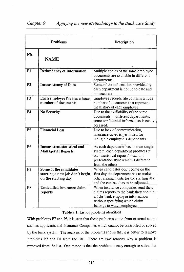
Chapter 9 Applying the new Methodology to the Bank case Study
Problems Description
NO. NAME
PI Redundancy of Information Multiple copies of the same employee documents are available in different departments.
P2 Inconsistency of Data Some of the information provided by each department is not up to date and not accurate.
P3 Each employee file has a huge Employee records file contains a huge number of documents number of documents that represent
the history of each employee. P4 No Security Due to the availability of the same
documents in different departments, some confidential information is easily accessed.
PS Financial Loss Due to lack of communication, insurance cover is permitted for ineligible employee's dependants.
P6 Inconsistent statistical and As each department has its own single Managerial Reports system, each department produces it
own statistical report format and presentation style which is different from the others.
P7 Some of the candidates When candidates don't come on the starting a new job don't begin first day the department has to make on the starting day other arrangements for the starting day
and the contract has to be adjusted. PS Undetailed insurance claim When insurance companies send their
reports claims reports to the bank they contain all the bank employee information without specifying which claim belongs to which employee.
Table 9.1: List of problems identified
With problems P7 and P8 it is seen that these problems come from external actors
such as applicants and Insurance Companies which cannot be controlled or solved
by the bank system. The analysis of the problems shows that it is better to remove
problems P7 and P8 from the list. There are two reasons why a problem is
removed from the list. One reason is that the problem is easy enough to solve that
210

Chapter 9 Applying the new Methodology to the Bank case Study
it is not worth the trouble of setting up a development project to solve it. The
other reason is that a problem is hard enough to solve that a development project
cannot solve it.
Both problems P7 and P8 have a mixture of these two reasons. In both cases the
external agencies can be asked to improve their procedures to correct the problem.
This request is an easy step to take, but if the agencies fail to comply any further
action by the bank the problem becomes very difficult to solve.
9.1.1.3 List groups of people or agencies that are affected by the
problems identified.
After analysing the problems to be solved, it is possible to determine the
boundaries of these problems. This process can be done by identifying the groups
of people that are affected by these problems. These groups are:
• Personnel
• Compensation
• Finance
• Training and career development
• Recruitment
9.1.1.4 Develop a matrix of the problems to be solved VS problem
owners.
In this step, an empty matrix of problems identified against problem owners is
developed and distributed among problem owners in order to be filled out by
them. Each department in the human resources division was asked to write down
the problems that have an effect on it. This is presented in the matrix of Table 9.2.
This matrix was filled out by the problem owners themselves, with help from the
developer when required.
After the problems were discussed and the people affected by these problems were
identified in HR division, it was realised that there were six groups of problem
211

Chapter 9 Applying the new Methodology to the Bank case Study
owners, who can be correlated with the problems that have been previously
identified. Therefore the following matrix was developed:
Problems Problem Owners PI, P2, P3,P4,PS,P6
Personnel .
P2,P3,PS,P6 Compensation
PS Financial
PI,P2,P3,P6 Training and Career Development
PI, P2, P3, P4, P6 Recruitment
Table 9.2: Problems against problem owners in the Bank of Bahrain and Kuwait
After identifying the groups of problem owners in the bank organisation, a
representative from each group was chosen to help in the development process.
It has to be noted here that the process of identifying the problem owners involved
confronting problems with some of the users who are resisting change to the new
system. This problem was resolved by identifying these people then conducting a
meeting session with them and the top management to explain what was being
done, and that the task was not to make their job redundant but to help them
practice their job effectively. Incentives were also given by top management to the
users who could help in the development process. Some of the intensive that were
included:
• Users who help in the development process will have a good report, which
can help in their next promotion.
212

Chapter 9 Applying the new Methodology to the Bank case Study
• BBK offered some valuable prizes for users who are heavily involved in
the developing process.
The project group contains the following members.
• John J ohnson IT department
• Hussain Bustami
• Personnel Asst. Manager Essa Hassan
• Training Assit. Manager Ahmad Mustafa
• Compensation Assist Manager Shaikha Taleb
department.
• Financial Assist Manager Atef Hameed
Recruitment department
Personnel department
Training department
Compensation
Financial department.
9.1.2 Make a Quantitative Study for Each Problem Identified.
9.1.2.1 Perform a cause-effect analysis for each problem
The first thing this group had to do was the cause-effect analysis for the problems
identified. The result of the problem analysis is represented in a cause-effect
graph, Figure 9.2, which is a directed graph in which nodes represent problems
and arrows point from cause to effect.
213

Chapter 9 Applying the new Methodology to the Bank case Study
Figure 9.2: Cause-effect graph of Human Resources
During the cause effect analysis for the bank, a number of important problems
were discovered. One cause of the employee starting date delay problem is that
214

Chapter 9 Applying the new Methodology to the Bank case Study
the departments within the Human Resources Division have no coordination
between them. This problem, in turn, is traced back to the lack of communication
problem between departments in HRD. The problem of no coordination is added
to the problem list.
Another problem caused by the lack of coordination is the problem of
compensation cover. The rule of compensation for an employee's dependent thus:
When the dependant reaches a certain age the dependant cover should stop. The
Compensation department complains that the Personnel department does not
inform them when the employee's dependants reach the age that the compensation
cover should stop. This problem causes the bank to spend more money than it
should for compensation cover.
The redundancy of information caused by the multiple copies of the same
employee document being kept in different departments causes another problem,
which is the increasing amount of paper consumption in the bank, which in turn
affects the overspent budget.
The problem of statistical and managerial reports was identified in the discussion
with the management. Their complaint was that each department sends reports in
different formats, they would like to see a consistent form of report for all
departments. This problem also increases the paper consumption. Every time the
manager does not like the format of the report he has to send it back to be
reformatted.
Finally, the problem of information redundancy and the problem of lack of
coordination cause the problem of data inconsistency. The multiple copies of
employee documents in different departments and the lack of coordination mean
that some erriployee documentation has inconsistent information. For example, if
an employee position has changed without the employee file being updated within
a certain department then this information will be different from other
departments.
215

Chapter 9 Applying the new Methodology to the Bank case Study
9.1.2.2 Conduct a session with problem owners to discuss and approve
updated problems.
In this session the problems that are added or deleted from the list are discussed
with the problems owners in order to finalise the list of problems. The problem list
was updated accordingly as is depicted in Table 9.3.
Problems Description
NO. NAME
PI Redundancy of Duplicate documents of the same employee information are available in different departments.
P2 Inconsistency of data Some of the information provided from departments is not updated and not accurate.
P3 No security At the end of every month the Financial department send the salary sheet to the accountant in order to pay the salary to the bank employee. This sheet exposes to the accountant employee all financial information about the other employee records in the bank.
P4 Each employee file has Employee files contain a huge number of a huge number of documents that represent the history of each documents employee.
PS Financial loss Due to lack of communication the insurance cover is permitted for ineligible employees' dependants.
P6 Inconsistent statistical Each department has its own single system. and managerial reports Each department produces it own statistical
report format and presentation style which differs from the others.
P7 Employee starting date When a new candidate is employed, some of delay the departments do not inform the personnel
on the day the candidate commences hislher work.
PS Huge consumption of A lot of paper is used everyday due to the paper problem of information redundancy and the
fact that there are no standard reports. P9 Lack of Coordination No coordination between HRD departments
Table 9.3: List of updated problems for the Bank of Bahrain and Kuwait
216

Chapter 9 Applying the new Methodology to the Bank case Study
9.1.2.3 Produce a matrix of the updated problems VS problem owners.
The matrix of the problems against problem owners was also updated as can be
seen in the Table 9.4:
Problems Problem Owners PI, P2, P3,P4, P6,P7,P9 Personnel
P2,P3,P5,P6,P9 Compensation
P5,P8,P3, P9 Financial PI, P2, P3, P6, P9 Training and Career Development
PI,P2,P3,P4,P6,P9 Recruitment Table 9.4: Updated problem agamst problem owners m BBK.
217

Chapter 9 Applying the new Methodology to the Bank case Study
9.1.2.4 Issue a matrix of problems quantified.
In addition to doing a cause-effective analysis, a quantitative study should be
made to the problems in order to decide whether to invest in the solution process
or not.
Problems Ouantification NAME
PI Redundancy of At least six copies of the same employee document information (papers of contract) are available in the following
departments: - Recruitment - Personnel - Training and career development - Compensation - Employees own department - Financial
P2 Inconsistency of data - Number of errors could not be determined because there was no record kept for that purpose.
P3 EacH employee file has Each Employee has an average of 15 static a huge number of documents (Passport, Civil ID, Driving License, document Residency, Marital Status, Dependants) and 50
dynamic documents per year such as: - Leave - Memos - Training certificates - Promotion
P4 No security Approximately 24 times a year the bank employees complain that their personal information is not secure enough.
PS Financial loss 75% of the bank employee are married. 10% of this category should not renew the scholarship of their children because their age is above the predefined scholarship schema.
P6 Inconsistent statistical Some managerial and statistical reports are returned and managerial reports for corrections four or five times from some
departments. P7 Employee starting date This happens almost 3 times a year.
delay PS A huge consumption of 5-10 packets of 500-sheets are consumed every day.
paper P9 Lack of Coordination 5-6 times a month the employees of HRD
complains that there are no coordination between them
Table 9.5: Quanl1fied problems matnx
218
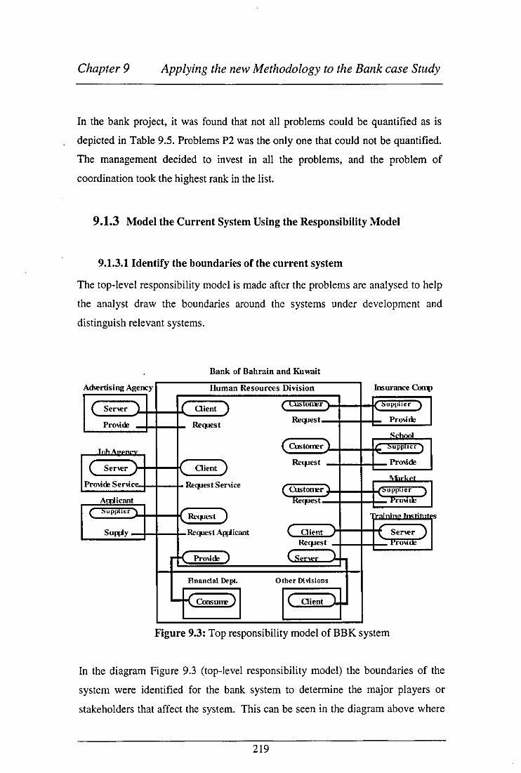
Chapter 9 Applying the new Methodology to the Bank case Study
In the bank project, it was found that not all problems could be quantified as is
depicted in Table 9.5. Problems P2 was the only one that could not be quantified.
The management decided to invest in all the problems, and the problem of
coordination took the highest rank in the list.
9.1.3 Model the Current System Using the Responsibility Model
9.1.3.1 Identify the boundaries of the current system
The top-level responsibility model is made after the problems are analysed to help
the analyst draw the boundaries around the systems under development and
distinguish relevant systems.
Bank of Bahrain and Kuw.ti!
Achertising Agency Imurance Con1>
C Ser",r ) ( Oien! ) ( )
Re<pest ,~
Pro\ide Re",es! School
r"h A. er. ) ~upp.'"
( Oient) Re",es! Pro\i.de
Sener
.. ,""re ReCJ.lest Senice ( ,upp"" )
~ . Pro"'"
) , r •• nh
SuWy Awican! ( Oient Ser",r ) . rro\tne
K PrO\ide) { Ser",r J.
Flnancial Dept. Other Divisions
-K J ( Oient ).
Figure 9.3: Top responsibility model of BBK system
In the diagram Figure 9.3 (top-level responsibility model) the boundaries of the
system were identified for the bank system to determine the major players or
stakeholders that affect the system. This can be seen in the diagram above where
219

Chapter 9 Applying the new Methodology to the Bank case Study
the major players are: The bank system, Advertising agencies, The Applicant, Job
agencies, Insurance companies, Schools, Market, and Training Institutes. Figure
9.3 shows the structural relationships and the functional relationships between the
bank system and the external agents that affect the system. The structural
relationships represent the service contract in the real world as it exists between
the bank system and the external agents. On the other hand, the functional
relationships depicted in the diagram as thin lines show the nature of the structural
relationships between the bank and the external agents. For example, the bank
can request the service from an advertisement agency and the advertising agency
has the responsibility of providing that service to the bank. In the same way the
bank can request candidates for a certain job vacancy and the applicant has the
responsibility of supplying the documents requested.
The function of agents can be seen through the functional relationships between
them. These ~elationships embody the policy of the bank, for example, in the
relationship between the job agencies and the bank, the service provider is
affected by the server and the request service is affected by the client agent.
9.1.3.2 Identify responsibilities, obligations and activities for each
department involved.
This section shows the pool of responsibility that comes out from the contractual
relationship with external as well as internal agents and from the implementation
of the organisation's policy. Each obligation is listed under the responsibility that
it is related to. By keeping responsibilities and its associated obligations together,
it is possible to track the policy that is implemented in the Bank of Bahrain and
Kuwait for the HRD.
220

Chapter 9 Applying the new Methodology to the Bank case Study
Recruitment Department
A - Responsibilities
The responsibility of the Recruitment department is to manage the
manpower plans and the organisational requirements for additional staff.
B - Obligations
I. Carry out salary assessment surveys
2. Advertise for vacant positions in the bank.
3. Liases with recruitment agencies for the employment of specialised
positions that cannot be filled from the local market.
4. Manage files of applicants.
5. Make an interview with suitable candidates
6. Negotiate salary based on the organisation policy.
7. Confirm applicants' qualifications and medical status.
C - Activities.
1. Carry out a salary assessment survey
• Communicate with Compensation department on salary
assessment.
• Investigate, the local market to assess the salaries for required
positions.
• Verify qualifications required for each position.
2. Advertise vacant positions in the bank.
• Contact departments for the qualifications required for each vacant
position
• Place advertisements in the local media
• Send required job information to recruitment
3. Liases with recruitment agencies
• Contact advertisement agencies in international media.
• Send company advertisement to international media agencies.
• Contact head hunting companies
4. Maintain files of applicants.
• Collect application forms from candidates.
221

Chapter 9 Applying the new Methodology to the Bank case Study
• Categorise applicants' application forms.
• Send candidates' application forms to departments.
5. Make an interview with chosen applicants
• Collect application forms from departments
• Keep unselected candidats' forms in a filling system.
• Inform selected candidates about interview time
• Inform the concerned department about the interview time
• Meet with candidate and representative from the concerned dept.
• Meet with department representative to confirm selected candidates
6. Negotiate salaries with chosen applicant based on the
organisation policy.
• Request organisation policy for employment procedure.
• Meet with applicant to confirm his/her qualifications and medical
status.
• Negotiate salary with applicant.
• Agree with applicant on final salary.
7. Accept chosen applicants' and sign contract.
• Sign employee contracts and obtain signature from applicant
• Set with chosen applicant the starting date.
Personnel
The purpose of this department is to manage the personal information of the
employees in BBK. The personnel module is the starting point of the employee
data, since the employee data must be entered first before any other transaction.
A - Responsibility
Managing and directing the personnel function and providing proactive
support to line management in order to achieve the corporation's goals
efficiently and cost effectively.
B ·Obligations
• Obtaining approval of senior executive management on benefits
plan.
222

Chapter 9 Applying the new Methodology to the Bank case Study
• Controlling passports, visas and residency operation for the bank's
staff.
• Monitoring grievance and penalty action for staff.
• Relating effectively to the Financial Division.
C - Activities
1. Personnel policies • Define all types of termination (Resignation, Layoff)
• Define all type of leaves (Annual Leave without Pay, Annual
Leave with Pay, Sick Leave, Maternity Leave, Pilgrimage
Leave)
• Define Holidays, Shifts and Office Hours
• Confer with other di visions in the bank on personnel policies
and procedure.
• Get approval from executive management on all staff
benefits.
2. Legal documents • Monitor and check expiry of and renew visas/work permits
of the employees and their dependants.
• Create a good relationship with government authorities to
facilitate official work of the bank as required.
3. Monitor employee activities • Keep regular time attendance sheets for each employee
• Keep track of employee penalties, deduction and warning
memos.
4. Relate effectively to the financial division • Send all employee promotion reports to financial division.
• Send all employee penalty reports to financial division.
223

Chapter 9 Applying the new Methodology to the Bank case Study
The Training and Career Development Department
A-Responsibility
Assessing staff development and training needs in coordination with
various organisational units and participating in organising and
administration in-house training courses.
B-Obligations
• Manage the training function to ensure staff are developed to
meet the increasing challenge and demand of an expanding
business.
• Organise and administrate in-house courses and arrange for
external courses identified by line management.
• Assess each course and recommend requirement on content,
presentation and timetable.
• Monitor the selection, progress and final assessment of
course members.
• Establish an effective relationship with outside training
agencies and related organisations.
C-Activities 1. Manage the training functio~ to ensure staff are
developed to meet the increasing challenge and demand
of an expanding business.
• Confer with other departments to analyse training needs.
• Develop individual training plans to meet recognised
development needs.
• Prepare and schedule the training programs.
• Check employee files to find out which employee needs to
take which training course.
• Check overall training budget to determine the bank's
training program.
• Prepare monthly/quarterly training statistics for executive
management review.
224

Chapter 9 Applying the new Methodology to the Bank case Study
2. Organise and administrate in-house courses and arrange
for external courses identified by line management.
• Check if training courses can be given inside the bank or not.
• Coordinate with outside training agencies in order to provide
the required course.
• Make sure all training courses offered are within the
organisation plan.
• Set the appropriate time for giving the training courses
according to the employee schedule.
• Provide suitable software and hardware that will be used in
the training courses.
• Select training staff from inside or outside the bank that are
most suitable for teaching the required courses.
3. Assesses each course and recommend requirement on
content, presentation and timetable.
• Prepare an assessment sheet for each training course.
• Distribute assessment sheets to all trainees on each training
course.
• Evaluate trainee assessments and make recommendations to
be taken into consideration for future courses.
4. Monitor the selection, progress and final assessment of
course members.
• Obtain candidates names from all departments
• Check candidates qualification files
• Select from candidates who should attend the offered training
courses.
• Send letter of confirmation to inform selected candidates
• Assess the performance of all candidates who attend the
offered courses.
5. Establish an effective relationship with outside training
and related agencies.
• Send greetings cards from time to time to outside training
225

Chapter 9 Applying the new Methodology to the Bank case Study
organisations.
• Contact outside training organisations to determine courses
offered.
• Send a list of future training courses required to outside
training organisations.
Compensation department
A-Responsibility
Supervise and control various compensation operations, staff
benefit activities and salary administration including approval of
payroll and any other staff financial settlements and administration
of staff insurance policies.
B-Obligations
• Direct and control daily activities related to staff benefits and
compensation transactions.
• Administrate salary scales and recommend modification to
salary scales and annual merit increments as appropriate.
• Administrate performance appraisal and salary review for
staff and trainees including the implementation of merit.
Increase guidelines and trainee salary progression grid.
• Administrate staff insurance policies including processing
any claim according to terms and conditions of policy
wordings and the approving of payment of premiums and
final settlements with underwriters.
C-Activities • Direct and control daily activities related to staff benefits and
compensation transactions.
• Receive notifications of a change of employee status from
other departments.
226

Chapter 9 Applying the new Methodology to the Bank case Study
• Update staff benefits according to employee status.
• Calculate employee benefits from leave compensation, ticket
compensation, new child compensation, etc.
• Administrate salary scales and recommend modification of
salary scales and annual merit increment as appropriate.
• Check the salary scale with the outside market on a yearly
basis for each required position in the bank.
• Send the recommended modification to salary scales to the
Recruitment department.
• Study the salary scales of the employees who take training
courses in the bank.
• Recommend an increase of salary for employees who take
valuable training courses.
• Administrate staff insurance policies including processing
any claim according to the terms and conditions of the policy
wordings and approving payment of premiums and final
settlements with the underwriters.
• Check all insurance claims sent to the Bank.
• Check which insurance claims belong to each employee.
• Check terms and conditions before payment
• Approve payment of premiums.
• Make sure that payments to insurance companies are
provided on time.
• Review and approve regular monthly reports generated for
the Information System unit, accounting unit and
compensation as well as reviewing the benefit statistical
report and passes for authorisation.
• Issue a statistical monthly report on all compensation
transactions with copies sent to Accountants, management
approval, Information System Department.
227

Chapter 9 Applying the new Methodology to the Bank case Study
9.1.3.3 Model the current system using the responsibility model
This involves decomposing the bank system into its subcomponents as depicted in
the diagram Figure 9.4. By decomposing the bank system into sub-agencies it
was possible to explore and draw out the implications of how the organisation was
structured. It was also possible to use these diagrams to elicit requirements by
asking questions such as " What is the communication medium through which the
functional relationships flow?" and "what are the responsibilities that reside
within the structural relationships?"
The purpose of making a current responsibility model was to be able to discuss
possible changes to the HRD system in the next step. The responsibility model
will be the platform for generating and discussing alternative solutions. In Figure
9.4, the rectangles are used to represent agents and agencies, while the rounded
rectangles are used to depict the structural roles that a particular agent or agency
may hold.
228

Chapter 9 Applying the new Methodology to the Bank case Study
Bank of Bahrain and Kuwait
Advertismen Human Resources Division
Agency Recruitment CopensaUoD Insurance §g Depl Depl Medical Company
nsurance I( server r Client} Request -0- --<. Provide!)
Am~lication (Peer Peer)
School andidat Salary School
I (Pro,lder }- €riJ- Request) and Request -§£}- -{ Provider } Benen.
,h andhfat s I (ConsumeJ ~ Provide)
I ( server }--S Client} Market
Salary Provider} Request g -{ Provider}
Provider)
Vuncy ;-f{ Provider}
£$ personnel training and
Si ncd ....IlI:IL- Employee Develo[!!!!ent Course Training
Co tract I (Pro>'ideo)-~ -{ Consumcg Coordinatlo Institute
Iq ~ ( Client K Server rtonsume~
(Pro>'ider 1
I (Pro>'ider (Consume
f.mployc I ( Pro,jderr r-
I (Accept }r- &r-;] Su able £mpl yee
:Zf7" Other Financial
Divisions tlfi Divi
; ( Pro\irle ~Consume~
Request)
r Request) Training
( Accept .n Employee
,t Provide In~
Certificates I { Request Doe
Figure 9.4: The Existing system for the human resources division
Diagram Figure 9.4 concentrates on the structural aspects of the organisation that
each agent is responsible for.
229

Chapter 9 Applying the new Methodology to the Bank case Study
Recruitment Agent
The process of recruitment in the Bank system starts when one of the departments
sends a request to fulfil a vacant position. This context is depicted in the
relationship Request-Provide between other divisions and the Recruitment
department in the human resources division. The diagram shows the Recruitment
department has a responsibility to fulfil towards other departments. This
responsibility is to look for suitable candidates for any vacant position in the bank.
After the Recruitment department obtains the other divisions' requirements it has
the responsibility to contact the advertising agencies and job agencies, as does the
new applicant in order to look for the suitable candidates for the new position.
This is described in the Request-Provide, Client-Server relation~,hips between the
Applicant, Advertising agencies and Job agencies and the Bank system. After the
Recruitment department receives all application fonus it starts to categorise them
as to who is most suitable for the job. It then sends the infonuation on the suitable
candidates to the associated department. This is again described by the Provide
Request relationship. When the requested department selects the candidate, the
Recruitment department has the responsibility of interviewing the applicants,
negotiating the salary, and preparing the contract to send to the Personnel
department.
If the Recruitment agent In the Bank system fails to properly fulfil its
responsibility towards the applicants, there is a set of formal steps that may be
invoked to resolve the situation. The Provide-Request structural relationship
between recruitment and Applicant agencies depicts this.
Compensation Department
The Compensation department controls the staff benefit activities and salary
administration. To be effective the Compensation department and the
Recruitment department has to work as a team in order to set the right salary for
the new candidate in the process of salary negotiation. The Peer-Peer relationship,
defines this process of coordination. This is a yearly process where the
Compensation department has to check the scale of salaries in the market and
230

Chapter 9 Applying the new Methodology to the Bank case Study
provide the Recruitment department with the updated information. The
responsibility upon the Compensation department is illustrated in the
relationships: Request-Provide relationship between the bank and the outside
market to obtain the salary scale for all candidates applying to the bank. The
Compensation department will also check to see if the candidate has some
authentication token attached to be eligible for insurance cover and school
services, this process is defined in the Request-Provide relationship. After all the
candidates' information has been obtained, the Compensation department will
send the information back to the Recruitment department so they can prepare the
final contract and send it to the Personnel department. This is illustrated in the
Provide-Consume relationship between the compensation and Recruitment
departments.
Personnel Department
After accepting the candidate in the bank, the personnel agent obtains the
employee contract from the Recruitment department to keep in their database.
The context of this activity is described in the Provide-Consume relationship. In
addition, the Personnel department has the responsibility of providing the starting
date for the new employee (depending on the starting date written on the contract)
to the financial division in order to start his/her salary, this is defined in the
Provide-Consume relationship. The Personnel department has the responsibility of
holding all employee history data in the bank organisation. This is depicted in the
relationship Supplier-Accept between other divisions and Personnel department.
Training and Development Department
This department is responsible for assessing staff development training needs with
various organisational units. For the training and development department to
prepare the training plan it has to request employee information from all bank
divisions and generate requirements on whom needs to be trained. This is
depicted in the Provide-Consume relationship between the Training and
Developments department and other divisions. The training plan will be
distributed to all bank divisions so the departments can inform the employees
concerned. This is depicted in the Provide-Accept relationship between the
231

Chapter 9 Applying the new Methodology to the Bank case Study
Training and other divisions. The Training department is also responsible for
organising in-house courses and arranging by request the appropriate external
courses by contacting the external training institutes. This is defined in the
Client-Server relationship between the bank and the training institutes. After the
employee has taken the course the Training department has the responsibility of
sending his certificate to his department so it can be stored in the files and a copy
sent to the personnel dept from the department itself. This is again defined
through the Provide-Consume relationship between the training and other
divisions.
9.1.4 Identify the New System Goal (Change Needs) and Requirements.
9.1.4.1 Conduct a session with problem owners to specify the new
syste.m goals.
After finishing the description of HRD current system. the problems were
identified and the problem owners were established. Before investigating the
possible changes to the current situation. the user goals of the bank had to be
specified in order to know how to evaluate solution proposals. These goals were
reached by interviewing the bank problem owners and asking them what they
would like to achieve. The discussion revealed the following list of goals:
Personnel: 1. Documents in the employee files should be minimised.
2. Only authorised persons should be able to access the employee files.
3. Better communication procedures should be implemented among all
divisions.
Compensation: 1. All changes to employee dependent information should be provided to the
Compensation department.
2. All benefits and cover that are being provided to ineligible employees
should be stopped.
232

Chapter 9 Applying the new Methodology to the Bank case Study
Recruitment: I. New candidate application forms should be stored in a database system.
2. Ajob description should be made for all the organisation's work positions.
Training and carrier development: 1. All employees' educational information should be provided to the Training
department.
2. All Bank trainees should be informed about the training course timetable.
3. A good relationship should be established with other training agencies.
9.1.4.2 List the new system goals.
Now we can shorten the goals list above by moving to a higher level of goals in
order to reach an agreement between problem owners. After negotiation with the
problem owners of the bank the following goals were reached:
NEED REFERENCE Goals CODE Gl Multiple documents in employee files should be
minimised. Gl.l Emplovee documents should be uPdated. G1.2 All duplicated documents should be minimised.
Employee documents should be secured. G2
G3 All Divisions should have good communication procedure.
G4 The service of the Compensation department should be optimised.
G5 New candidate information should be kept in a database svstem.
G6 All report formats should be coordinated.
Table 9.6: List of goals
The goals in Table 9.6 are general enough to be related to the business mission of
the HRD. Yet specific enough to be related to the goals of the different problem
owners.
233

Chapter 9 Applying the new Methodology to the Bank case Study
9.1.4.3 For each goal find-out the problems that prevent it from being
achieved.
For each goal, in order to identify the reasons why it is not achieved, a list of
problems that prevent the achievement of the goal has to be issued. To do this, a
matrix of problems against goals is issued in order to find clusters of related
problems. This is shown in Figure 9.7.
9.1.4.4 Cluster problems into groups of similar problems that are related
to the same goals.
There is no algorithm to do the clustering; the understanding of the situation
gained by analysing it from different angles should suffice to make the clusters.
Each cluster defines a change need that will act as a goal of the development
process. As is shown in Table 9.7, an example of clustered problems for the bank
case study would be that for goal G I there are three clustered problems, which are
PI, P2, and P3.
9.1.4.5 Issue a matrix of problems against goals (Change needs).
When the problem list is compared with the goals of the project team then the
change needs matrix is developed as shown in Table 9.7.
For each change need (project goal), the problems that were intended to be solved
were listed with the objectives that the change should help to achieve.
234

Chapter 9 Applying the new Methodology to the Bank case Study
NEEDS DESCRIPTION PROBLEMS Goals
NI All employee data should be PI, P2, P3,P9 GI accurate and up.to·date.
N2 Coordination and PI, P2, P3, GI,GI.I, communication should be P4,P5,P6,P9 GI.2, G3, G4 applied among all G6 departments in order to reduce multiple copies of employee documents and reduce bud2et expenses.
N3 Only authorised persons PI, P3, P9 G2 should access employee records.
N4 The compensation system P2,P5,P9 G1.I, G3, G4 should be improved.
N5 The recruitment process P7,P9 G5 should be improved.
N6 Managerial and statistical P6,P9 G6 reports should be improved.
Tabte 9.7: A matrix of problems against goals (change needs).
9.1.5 Generate a List of Change Alternatives.
9.1.5.1 Meet with problem owners.
At this stage the project team meets again in order to carry forward their ideas of
the changing alternatives that could be implemented in the new system. These
ideas are written down only without evaluations. See Table 9.8 for the list of
change ideas produced at HRD.
9.1.5.2 Evaluate change needs according to the problem owners' point
of view.
The change alternatives were then evaluated by examining different alternatives of
changing flows and/or activities. Could the flow occur in another way? Could the
activities be performed in another manner? The answer to these questions led to
the change alternative document in Table 9.8. At this process the bank problem
owners were able to develop different models (AI, A2, A3, A4, AS) until they
235

Chapter 9 Applying the new Methodology to the Bank case Study
accepted an ownership of these models and felt they can represent their
requirements.
9.1.5.3 Issue a matrix oC change alternatives.
Table 9.8 shows that all the alternatives involve changes to the existing
information system of the Human Resources Division. It also shows that the lack
of communication problem in the Human Resources Division causes most of the
other problems between departments.
Alternatives Description At The Recruitment department
should have a database system in order to keep track oC all new candidates application Corms.
A2 An automated information system is required in order to integrate all departments in the Human Resources Division. This is to enhance the communication process and support the services provided to the bank.
A3 An automated system should be implemented in order to improve communication between Personnel and Recruitment departments.
A4 Facilitate automatic reporting on employees who are ineligible for insurance or school cover.
AS Facilitate the production oC managerial and statistical reports with standard Cormat by implementing an automated inCormation system.
Table 9.8: A matrix of change alternatives
236

Chapter 9 Applying the new Methodology to the Bank case Study
9.2System Modelling
9.2.1 Choose the Best Alternative Package for the Organisation.
9.2.1.1 Present alternative packages of related changes to be investigated.
It was then time to make a package of one or more change alternatives that were
worth investigating. The responsibility model was used to investigate the package
allowing discussion about the package and comparison with the current situation.
The packages that were constructed are as follows:
I. A I: Develop a database system for the Recruitment department.
2. A2+A3+A4+AS: Implement an automated information system.
It was realised that only the first alternative solves the problem of the Recruitment
department and perhaps the Personnel department as well, but it does nothing for
the other departments in the Human Resources Division (HRD.)
All other alternatives require an automated system. It was concluded, therefore,
that if an integrated system were developed for H.R.D it would cover all other
alternati ves.
9.2.1.2 Evaluate each package solution.
An investigation was conducted at this stage to see which problems are introduced
by each package, and for whom. To produce this, a matrix of problems against
problem owners was constructed for each package.
In the Bank project, a matrix was constructed for evaluating the alternatives that
were recommended from the project group. An "0" in an entry form means that
the problem is solved for the problem owner. An "X" means that a problem exists
for a problem owner. Table 9.9 contains the matrix for the automation package
(A2+A3+A4+AS) which gave the best score with respect to the bank development
goals.
237

Chapter 9 Applying the new Methodology to the Bank case Study
Personnel Compensa Training Financial Recruit -tion and carrier -ment
development PI. Redundancy 0 0 x of information P2. 0 0 0 x Inconsistency of data P3. No security 0 0 0 0 x'
P4. Each 0 0 0 employee file has a large a mount of documents PS. Financial 0 loss P6. Inconsistent 0 0 0 0 0 Statistical and managerial reports P7. Employee 0 0 starting date .
PS. A huge 0 0 0 0 x consumption of paper. P9. Lack of 0 0 0 0 0
coordination
Table 9.9: Matrix of problems and problem owners for the automation package
(A2+A3+A4+AS)
9.2.1.3 Select the best package for the organisation.
In this step the sponsor is presented with a report on the evaluation of alternatives
and then chooses one of them.
In the bank project. after presenting the evaluation of alternatives to the sponsors
it was decided that package-2 is the' only alternative that could solve rnost of their
problems.
9.2.1.4 Pre-implementation impact analysis
Concerning the BBK case study the impact of the new changes was acceptable to
the Human Resources sponsors so there was no alteration to the original changes.
238

Chapter 9 Applying the new Methodology to the Bank case Study
9.2.2 Model the Required System Using the Responsibility Model.
9.2.2.1 Decompose the responsibility model in the change analysis stage
into obligations using the role model.
Figure 9.5 represents the restructuring and realignment of responsibilities that
would occur if the automated system were implemented. Several key
organisational responsibilities would have to be reassigned and realigned.
239

Chapter 9 Applying the new Methodology to the Bank case Study
Bank of Bahrain and Kuwait Human Resources Division
Advertismen Agency 1,:==::-1 Adverti ng
~(~se=n=er~l~~~nfu~~ ____ ~~~~j ~dical Insurance
~~~>t __ ~I ~surance Company
Appl i cation "'andidat
(Provider r 7.2:!:f
Job A~encies
, -DKProvider)
School School
Candida es ~~~>t----l-e!J--t.cove K Provider )
(smer )-~ Client)
Request)
Pro\-'ider)
Request
Consume
- Consumej Va aRey r- -<.. Provider)
I rt;w Elm oyee I L:.r-' personnel (?e denlts
Si ned Dep! Dfo
ht I (Provider} CepirkaJes
L.,J I ( Consum~ ""L.J'"
training and Development
(Supplier )-
Provider)
( Peer Peer )
'-- {onsum.g r_ I (Client UIIP oyee
(Provider} -{if;}--{ Consume9
(Provider (Provider )-Fmpl yet
(Accept - Inro
Su able Other =Lf Financial
ran idates Divisions Division
Iq I (Provider '- ( Consume~
Request)
Provider) Training
Il Accept an
Salary Market
.t:;:;;i;77-l=;==:;-"i /::::::;/ 1: Provider)
Course Training ( oordination Insti tute
--iB-KServer )
Figure 9.5: The future system for the Human Resources Division
240

Chapter 9 Applying the new Methodology to the Bank case Study
The personnel
In the new system other divisions will have the responsibility of informing the
Personnel department on which day the new employee started, this is called the
joining date. This is to distinguish between the date the employee is willing to
start work and the actual date that the new employee joins the organisation. The
context of this is defined in the relationship Provide-Accept between other
divisions and the Personnel departments. This is different from the old system
where the Recruitment department is the one that has the responsibility to inform
the personnel on the starting date. This process will solve the problem of the
contradiction between the starting date and the physical joining date of the new
employee. It will also solve the problem of the delay by the Personnel department
in informing the finance department to start processing the salary for the new
employee.
The Personnel department now has to make available to the Compensation
department the employee information needed in order to update the employee
dependent records. This is described in the Provide-Consume relationship
between the Personnel and the Compensation departments. In the old system the
Compensation department used to depend on the existing information in the other
divisions and the honesty of the employees. From Figure 9.5, the resources flow
between the Personnel department and the Compensation department can be
identified and the question, "What type of resources flows between the
departments; and who has access to this resources?" can be asked. To answer
these two questions, the type of resources that flow from the personnel to
Compensation department will only contain information about the employee
medical and dependant records. This is the only access right that the
Compensation department will have in the personnel information database.
Compensation department
The Compensation department will have the right to access the employee
dependants' data files to see the updated information on the employee dependants
only. This is to speed up the process of the Personnel department informing the
241

Chapter 9 Applying the new Methodology to the Bank case Study
Compensation department of any changes required to the employee dependent
information. This process will solve one of the problems of budget overspending,
which resulted from permitting ineligible employees' dependants having
insurance cover or school cover.
Training and career development
Training and development department will have access to the employee education
data file only. This is to help in assessing the staff training needs.
Training department will then have one more responsibility to fulfil, which is to
provide the Compensation department with a copy of the trainee certificates and
information when bank employees enrol on any training courses. This is depicted
in the Supplier-Consumer relationship between the Training and Compensation
departments. This is to solve the problem of delaying the benefit compensation
for the bank employees and also to assess the salary of the employee. In the old
system there was hardly any connection between the compensation and Training
departments. The original certificate will be sent to the Personnel department. The
Training and career development department now has to make a copy of the
trainee certificate and send the original to the Personnel department in order to be
kept in the employee history file. Then a copy will be sent to the concerned
division in order to be given to the employee. In the old system this document was
made available to the employee's division only.
Also in the new system the Personnel and Training departments have to work as a
team in order to develop the training plan in the organisation. This is depicted in
the Peer - Peer relationship.
9.2.2.2 Discuss the new assignment of responsibilities resulting from the
proposed system.
Recruitment department: One new responsibility has been assigned to the Recruitment department after modelling the system, which is:
242

Chapter 9 Applying the new Methodology to the Bank case Study
• To give information about new candidates to other divisions.
Other Divisions: A new responsibility has been assigned to all other divisions, which is:
• To give information about the new applicant starting date to the
Personnel department.
Personnel department: A new responsibility has been assigned to Personnel department, which is:
• To give to the Compensation department all information needed to
update the employee dependants' records.
Training department: Two responsibilities have been assigned to the Training department these are:
• To give updated employee training information to the Compensation
department.
• To give all employee training information to the Personnel department.
9.3 Socio-Technical Design
As mentioned in chapter-I, the aim of this thesis is to concentrate only on the first
two stages of the new methodology and leave stages 3 and 4 for future work (see
chapter-10, section 10.4 for future work). Therefore this research has ended here.
However, as an update, the Bank has indicated me that they have given the study
to a consultant company in order to review it and maybe add their suggestion to it.
Feedback from the consultant company has arrived which shows that the new
methodology is effective. The feedback from the consultant company is given in
Appedix-2.
243

Chapter 9 Applying the new Methodology to the Bank case Study
9.4 Concluding Remarks
The field work study presented in this chapter demonstrates the use of the newly
developed methodology in the real world. The new methodology was
implemented in the Bank of Bahrain and Kuwait in the state of Kuwait to study
the current system in the Human Resources Division and to give advice for the
future system of the Division.
Using the BBK case study the first stage of the new methodology concentrated on
the importance of people (endusers, managers, and funders) and their problems in
the bank organisation. The benefit from this process was to identify the
fundamental causes of users' problems in the existing HRD system, specify the
changes that need to be made and give alternative solutions to the current
problems. In addition the new methodology enable the users to carry out the
problem analysis themselves by providing them with a series of easy tools, tables
and method steps. For example, in BBK, the problem tables were given to
different levels of problem owners (executive managers, middle managers, and
lower end users) to be filled out in order to capture their requirements. Another
tool is the cause effect graphs that were understood by all different levels of
problem owners in the BBK organisation. The feedback from problem owners
concerning these tools is that the tools are easy to use and understand. These tools
enable the problem solver to share a common language with the problem owners
in order to elicit and capture their requirements
The advantages of spending a lot of time on identifying the users' problems and
needs in the first stage of the methodology are as follows:
• To educate the users to give a better understanding of the organisation. In
the bank case study, this was done by letting the bank problem owners
discuss problems and analyse their work themselves by providing them with
a series of easy tools and methods.
• To support the communications process between the users and developers
making sure that they talk the same language. In the bank case study, it was
244

Chapter 9 Applying the new Methodology to the Bank case Study
not possible for the problem owners to understand what was happening in
the development process until all the tools and techniques were explained
and illustrated. This process made it easier for the developer and problem
owner to understand each other and use a common language.
• To give a better understanding of the users' requirements. In the bank case
study, a lot of time was spent on identifying user needs and objectives. This
is shown in sections 9.1.4 and 9.1.5. This process was carried out through a
lot of negotiation and compromise between the bank problem owners
themselves with the help of the developer.
The feedback of the bank users concerning the various meetings was that they felt
tired of attending these meeting but then on the other hand they felt they had never
understood the organisation and their work as much as they did afterwards.
Secondly, listing the needs and goals of BBK in tables and trying to solve the
problems that prevent these goals from being achieved enabled the project team to
identify the business strategy of HRD and determine what the new system should
provide for the bank in" the future. This issue is not addressed by the ORDIT
methodology but addressed by ISAC and the new methodology. See Table 9.10.
In the modelling stage the responsibility model was used instead of the A-graph
used in the ISAC methodology in order to implement the enterprise modelling
used in ORDIT. This is to shift from identifying the business strategy and user
needs in the first stage, to the organisational issues and needs in the second stage
of the new methodology. Through the process of listing the responsibilities and
obligations for each department in the Human Resources Division it was possible
to determine the division main policy. In the same manner, through listing the
roles of agents in each department, it was possible to identify the job description
of the division employees. Also using the enterprise modelling it was possible to
identify the realignment of the organisation structure according to the users'
requirements. This analysis proves the value of addressing the organisational
245

Chapter 9 Applying the new Methodology to the Bank case Study
issues and needs which are not addressed by the ISAC methodology but are
addressed by ORDIT and the new methodology. See Table 9.10.
The responsibility models in 9.4 and 9.5 provide a rich picture of the environment
as well as the roles of agents, information flow, the structural relationships and the
utilisation of. resources in BBK. These models were constructed through an
iterative meeting process between the analyst and the problem owners. The
feedback from the problem owners at the end of this process was that they found
these models easy to use and easy to understand. Also one critical advantage from
involving the decision-makers and problem owners in the redesign process is that
the problem of user resistance was solved, making it easier to discuss the redesign
of the organisation structure. At the end of the second stage the problem owners
will have made a decision on what type of computer system to obtain as well as
setting out the IT strategy for the bank system.
The problem of negative user attitudes to any information systems was resolved
by giving some incentives to users who can help in the development process. This
point is explained in section 9.1.1.4.
Table 9.10 below lists the factors and sub factors that were addressed by the new
methodology when it was applied to BBK. The table shows that when applying
the new methodology more problems can be solved than when using either ISAC
or ORDIT. The blank cells mean that the methodology does not support the
analysis of a certain factor or sub factor.
246

Chapter 9 Applying the new Methodology to the Bank case Study
ORDIT ISAC New Methodolo~y
USER NEEDS 1111111111111111111111111 1111111111111111111111111111 111111111111111111111111111111 1- Stakeholder Support analysis support analysis support analysis and information and and representation representation
representation 2- Current attitudes to IT Partially support support analysis and
_._. analysis representation 3- User's job needs Support analysis ---- support analysis ORGANISATIONAL 1111111111111111111111111 1111111111111111111111111111 111111111111111111111111111111 NEEDS 1111111111111111111111111 1111111111111111111111111111 111111111111111111111111111111 1- Current work patterns Support analysis Support analysis support analysis and
and and representation representation representation
2- Infrastructure support support analysis and for IT ---- ---- representation
3- Problems identification Supports analysis Support analysis support analysis and and and representation representation representation
4- Pre-implementation support analysis and impact analysis ---- ---- representation
5- Organisational issues Support analysis support analysis and analysis and ---- representation
representation BUSINESS NEEDS 1111111111111111111111111 1l1li11111111111111111111111 111111111111111111111111111111 1- Business strategy and Recognises needs support analysis and
objectives ---- to capture representation 2- IT strategy support analysis and
---- ---- representation 3- Business mission Support analysis support analysis and
---- and representation representation SOCIO-TECHNICAL 1111111111111111111111111 1111111111111111111111111111 111111111111111111111111111111 NEEDS 1111111111111111111111111 1111111111111111111111111111 111111111111111111111111111111 I-Conventional technical Support analysis
needs analysis ---- and representation ----2-Socio-technical needs Support analysis Partially support support analysis and
analysis and representation representation
Table 9.10: Identification of the factors and subfactors that are addressed by
the new methodology compared with ISAC and ORDIT.
Analysis of Table 9.10 shows that all the factors that are supported by ISAC and
ORDIT are supported by the new methodology. But neither ORDIT nor ISAC can
addresses all the factors that are covered by the new methodology. For example,
247

Chapter 9 Applying the new Methodology to the Bank case Study
Pre-implementation impact analysis is neither addressed by ISAC nor by ORDIT,
but it is fully addressed by the new methodology.
The third and fourth stages were not completed in this case study. However, the
BBK has now passed the work on to a consultant company to review what has
been done so far and continue the project. The consultant company's review of the
work reported in this thesis is given in Appendix-2.
248

Chapter 10 Conclusions and Recommendations/or Further Research
Chapter 10
10.0 Conclusions
Conclusions and Recommendations for Further Research
Researchers in the area of software engineering have for long time used formal
methods as a means of specifying systems, They believed that if the system is
specified correctly using certain tools then various properties of the system could
be tested, In addition, a validation function may be performed on the system to
check that the developed system meets the requirement specification, The problem
that has confronted the formal methodologies is how correct the constructed
specification? By concentrating only on the functional aspect of the system, these
tools fail to capture correctly the context and the environment of the system,
Therefore, most of the formal tools ignore the capture of the non-functional
requirements that are essential for defining today's system, The resulting problem
facing system analysts who are using the formal notation is that they find
themselves constructing and validating a specification that does not accurately
reflect the needs and values of the system owners and system users,
ISAC is an example of a technical methodology using an activity model, which is
insufficient for addressing the non-functional requirements and the organisational
issues, However, the methodology has its strength in the user needs, and business
strategies, which are essential for the development ofIT system today,
ORDIT is a methodology that adopts the socio-technical approach in order to
capture the non-functional requirements of the organisation by placing the system
in its social context, In addition, it incorporates most of the organisational issues
that are essential for the development of IT system, However socio-technical
249

Chapter 10 Conclusions and Recommendations for Further Research
methodologies show a weakness by ignoring some of the issues such as business
needs and strategies that are also essential for the development of an IT system.
An evaluation criterion has been developed to examine the strength and
weaknesses ofISAC and ORDIT methodologies against the following four factors
namely:
• User needs
• Organisational needs
• Business needs and
• Socio-technical needs
Based on this evaluation criterion, this research introduces a new methodology
that can help in the requirement engineering process when developing an IT
system. This methodology is constructed by combining ISAC and ORDIT
methodologies to solve a certain set of problems, some of which are solved by
ISAC and some of which are solved by ORDIT, but neither of them solve all
the problems that can be solved by the new methodology. The evaluation
criteria framework shows that the new methodology has solved more
sub factors than the two methodologies can solve together 'individually (See
Table 9.11 in Chapter 9). These sub factors are:
• Pre-implementation impact analysis
• Infrastructure support for IT
• IT Strategy
The new methodology provides easy tools and modelling notation such as the
tables and enterprise modelling language that can be understood by the problem
owners and system analyst. These tools have been used for different problem
owners at different levels of the Human Resources Division (the top management
level, the middle management level and the user level). Their comments were that
250

Chapter 10 Conclusions and Recommendations for Further Research
these tools were easy to use and easy to understand. During the development
process these tools acted as a communication medium between the system analyst
and problem owners which made it possible for the system analyst to elicit the
. problems in the problem owners language and facilitated a debate with them.
The enterprise modelling language used in the new methodology made it possible
to model and represent the structure of Human Resources Division (HRD). The
benefits from using this model were to illustrate the positions of requirement
owners involved, identifying their roles and responsibilities within HRD so that
the requirement elicitation process could be demonstrated. Another benefit was to
identify the structural and functional relationships between the departments of
HRD. Using the responsibility model it was possible to model the current system
at an early stage and build a picture of what is going on in the HRD current
system. This process helped in transferring the requirements to the problem
owners themselves, making the problem owner share a common language with the
problem solver and thus enabling agreement that the correct requirement had been
captured. Listing the responsibilities and obligations helped in determining the
main policy ofHRD and identified the job description of the division's employees.
10.1 The Importance of A positive Attitude
Before applying the new methodology to BBK case study, it was applied to solve
the problems of the immigration system in the Ministry of Interior in Kuwait. This
case study was not successfully implemented for the following reasons.
• None of the department's managers agreed to be involved in the project
group. A possible interpretation of this behaviour was that they felt too
busy to participate in any work other than their job. So all they did was
tell their employees to attend the project meeting.
• From first meeting with the employees, it was realised that they were not
interested in attending the meeting. Even when it was explained to them
why it was important to attend, none of them wanted to participate in the
project. A possible interpretation of this behaviour is that they did not
251

Chapter 10 Conclusions and Recommendations/or Further Research
want to use new methods or techniques and they only wanted to stick to
what they know (fear of change).
• Another reason for the employees refusing to cooperate was that they felt
that it was the job of systems analysts to participate in the project and
therefore they did not want to get involved.
• After three meetings none of the employees were attending any more.
The reason was that they felt it was extra work for them and there was no
encouragement and incentives from upper management.
• Another interesting reason was that most of the projects that were done at
the Ministry of Interior followed the hard system approach. The users at
the ministry were hardly involved in negotiation or consulted for their
point of view and therefore played a passive role in all the projects that
were done at the ministry (and it seemed they were happy about it). One
of the c~mputer consultants at the ministry mentioned that users are only
consulted at the testing phase of the project, before implementation. This
is the only time that they are forced to work with the system so that they
can discover problems with it. He continued that at the end of the project
only the minor problems are fixed.
When the new methodology was applied to BBK bank, the attitudes of the
management were completely different. It was realised that they wanted to try
new methods to solve their problems and they were helpful in organising the
meetings as well. The most important thing they did was encouraging their
employees to get involved and above all they offered some incentives for
participating in the project. The experience of the Ministry of Interior has shown
the importance of a positive attitude for the success of the methodology. No
problems can be solved if the owners do not care about the problems and the
benefit of the methodology cannot be obtained unless the users want to improve
their performance.
252

Chapter 10 Conclusions and Recommendations for Further Research
10.2 Cost-benefit of the New Methodology Used in BBK
Although, the cost for using the new methodology mostly appeared in the time
spent in meetings between the system analyst and problem owners, there were
benefits, which compensated for that cost. The calculation of these costs and the
savings for one of the benefits is illustrated in Appendix!. To show the cost and
benefits in brief, the project group has met three times a week for three months for
average of 2hrs a session. The average cost of the group project is estimated as
8190KD (£16380). The cost of other employees involved in the project is
estimated as 6825KD (£13650). Therefore the total cost ofBBK bank for applying
the new methodology is £30030. On the other hand, offering just one benefit of
the new methodology, solving the employees' dependent compensation problem,
can compensate this cost. To illustrate this benefit, according to the bank problem
owners, 10% of the total employees are getting school and medical cover illegibly
every year because the bank current system cannot detect the illegible dependants.
The estimate of this cost is 15400KD (£30800) in the first year, see Appendix!.
Therefore it is realised that using the new methodology can compensate the bank
for their cost as well as an estimate saving of £770 for the first year only which is
a lot of money to consider. Some other main benefits that can be offered to BBK
are as follows:
• Developing the integrated system made it possible for all the HRD
departments to speed up all the information transaction, eliminate all
inconsistent and duplicated data. This process saved the bank time and
effort.
• Assigning an ID number for all bank employees made it possible for the
bank to hide the employee name from most of the financial transactions,
which made the private information secured from the public.
Altogether, it has been shown that the new methodology can serve better than
either ISAC or OROIT methodologies in the process of system development.
Finally, it is believed that this research has fulfilled its main aims, objectives and
proved its hypothesis. This is accomplished by developing a new methodology
253

Chapter 10 Conclusions and Recommendations for Further Research
that can be used to talk to different levels of problem owners, let them develop
models of the system until the desired model that captures their requirement is
accepted. In addition, the responsibility model was used to model the current and
future system of the bank and to identify the organisational requirement.
10.3 Requirement Elicitation Process
To point out the requirement elicitation process, one can look at the user
participation throughout the new methodology. This process does not end prior to
design and implementation as in conventional system but it is an ongoing process
throughout the system development life cycle. The reason for that it is believed
that requirements are developed over time as understanding of the problem to be
tackled improves. In BBK case study a project team was developed which
involved three main actors namely: the problem solver, problem owners, and
sponsor or stakeholders. The process of communication between them may be
regarded as a negotiation process, where potential problem owners of HRD
system explore and fully understand the requirements, agreeing on what they want
and what they need, while the problem solver becomes confident that they are
solving the right problem.
The new methodology follows a form of iterative process where the users of the
system participate in meetings and discussions held in the meeting room at
different times. Through these meetings, tables and modelling languages are used
to record and document all generated ideas. The facilitator, who acts as a
chairperson of the meeting, has a critical role in organising the work of the
requirement negotiation team. After each meeting, each member of the project
team has to meet with his/her department groups in order to discuss all new ideas
and have their feedback for the next project team meeting.
The new methodology also encourages partnership between the problem owners,
sponsor and project team members in order to discuss open issues and to validate
everyone's understanding of the information gathered especially in the new
system changes. In addition, The processes of helping the problem owners
develop their own models of the required system reveals that the transfer of
problem owners understanding of business practice to the problem solver, who
254

Chapter 10 Conclusions and Recommendations for Further Research
will translate it into a working computer system, is the key to effective
communication and requirement elicitation benefiting both parties.
Finally, a paper based on the contribution of this research, entitle "A new
methodology for requirements analysis" has been accepted for publication by
refereed international conference called "Australian Conference on Requirements
Engineering (ACR'99)", see Appendix-3.
10.4 Recommendations for Further Research.
This thesis has concentrated on the development of a socio-technical modelling
framework, which is taken from combining ORDIT and ISAC methodologies. The
purpose of this framework is to elicit, validate and verify the user and
organisational information system requirements. It is not claimed that the
framework of this integrated methodology is the best solution for the problem of
requirement elicitation. However, the basic principles could be built upon to
provide a more complete approach for requirement engineering.
One way to check the usefulness of the new methodology for the requirement
elicitation is to perform further case studies. Within this thesis one case study
taken from the private sector in Kuwait was used to examine the applicability of
the new methodology. This case study was drawn from the real problem, which
exists in the real world.
The most important and urgent recommendation is to examine the last two stages
of the new methodology, which are the Socio-technical design and
implementation. This would allow the organisational issues and business needs to
be mapped all the way down into the technical part of the methodology so that
their applicability could be explored and tested. It is also important to examine
how well the social requirement can be fitted into the technical requirements in
order to get the required system.
The new methodology could be applied to the government sector in Kuwait in
order to examine how the modelling notation of both the organisational and
information system worked and interacted. In addition, this case study will serve.
255

Chapter 10 Conclusions and Recommendationsjor Further Research
to identify the problem of the structural relationships in the interrelated
responsibilities that exist within the organisational structure in the public sector.
Another benefit of this case study would be to identify the strength and
weaknesses of the new methodology techniques.
The third recommendation would be to increase the integration of the
responsibility modelling techniques with other modelling techniques such as the
modelling techniques used in ISP (Information Strategy Planning), SSM (Soft
System Methodology), and ER (Entity Relationship Modelling). The benefit from
the integration process is to provide the modelling technique used in this thesis
with the ability to share information. Thus problem solvers would be able to
capture and utilise information about the organisational system in a way similar to
that represented in this thesis when using other forms of analysis. This process
would have the effect of minimising the time spent for capturing and representing
data, and maximise the use of the data that we already have available.
256

References
References
Aggarwal, A., Sharma,P. K. and Wadhwa, S. (1993), "Enterprise Integration System
A new Paradigm for Information Management". International Engineering
Conference, pp. 95-101.
Alexander, C. (1979), The Timeless Way of Building. Oxford University Press.
Alford, M. W., Ansart, J. p" Hommel, G., Lamport, L., Liskov, B., Mullery, G. P.,
and Schneider, F. B. (1985), Chapter Three - Acquisition Environment. In Lecture
Notes ill Computer Science - Distributed Systems, Methods and Tools for
Specification. An Advanced Course 190, (pp. 45 - 130), Springer-VerJag.
ANSA (1990), The ANSA Referellce Manual, Architectural Projects Management.
Ashworth, C. M. (I99 I), Structured Systems Analysis and Design Method (SSADM),
In The Software Life Cycle, pp. 168-188.
Auramaki, E., Lehtinen, E., and Lyytinen, K. (1988), A Speech Act Based Office,
Modelling Approach, ACM Transactions Oil Office II!/ormation Systems, 6(2), pp.
126-152.
Avison, G.E. and Fitzgerald, G. (1988), "Ii!/ormation Systems Developments
Methodologies, Techniques and Tools", Blackwell Scientific.
Beslmuller, E. (1988), "Office Modelling Based on Petri Nets", In ESPRIT 1988, Part
1, pp. 977-987, North Holland.
Bienert, A. and Schonenberger, D. (1993), Computer Aided Enterprise Modelling - A
global approach, Advances in Productioll Managemellt Systems, Elsevier Science
Publishers B. V.
Blumenthal, S.C. (1969), Management II!/ormatioll Systems, Prentice Hall,
Englewood Cliffs, H.J.
257

References
Blyth, Al.C, (1995), "Enterprise Modelling and its Application to Organisational
Requirements, Capture and Definition", PhD. Thesis, Newcastle University.
Boehm, B. W. (1976), "Software Engineering". IEEE Transactions on Computers, C-
25(12), pp. 1226-1241.
Booch, G. (1991), "Object Oriented Design with Applications". BenjaminlCummings
Publishing Company.
Cameron, l. R (1986), An Overview of lSD. IEEE Transactions 011 Software
Engineering, SE- 12(2).
Chen, P. P. (1976), The Entity-Relationship Model- Towards a Unified View of Data.
ACM Transactions on Database Systems, I (I), pp. 9-36.
Checkland, P. (1986), Systems Thinking, Systems Practice, Wiley.
Clegg, C. W., WaIT, P. B., Green, T.R. G., Monk, A, Kemp, N. 1., Allison, G. and
Lansdale, M. (1989b), People and Computers, How to evaluate your Company's New
Technology. Chichester, Ellis Horwood.
Coad, P. and Yourdon, E. (1991), "Object Oriellled Analysis", Prentice Hall.
Cunningham, R, Finkelstein, A, Goldsack, S., Maibaum, T., and Potts, C. (1985),
Formal Requirements Specification - The Forest Project. In IEEE International
Workshop 011 Systems Specification and Design (IWSSD), IEEE Computer Society
Press.
Dale, A G. (1983), Information System Developments. Department of Computer
Science, University of Texas. Austin.
Davenport, T. (1993), "Process Innovation: Reellgineering Work Through
Information Technology", Harvard Business School Press.
Davis, G.S. and Olson, M.H. (1984), Management Information Systems, 2nd Ed.,
McGraw-Hill, New York.
258

References
DeMarco, T. (1979), Structured Analysis and System Specification. Prentice Hall.
Dobson, J. E. (1988), "Representing the Real World", Technical No. 267, The
University of Newcastle Upon Tyne.
Dobson, J. E., and McDermid, J. A. (1990), An Investigation into Modelling and
Categorisation of Non-Functional Requirements, For the Specification of Surface
Navel Command Systems, Technical No. YCS 141, The University of York.
Dobson, J. (1993), "Organisational Requirements Definition for Information
Technology System", Theory, Use and Integrative Aspect of IS Methodology, Conf.
1993, British Computer SOCiety, pp. 295-308.
Eason, K. D. (1988), Information Technology and Organisational Change. London,
Tylor and Francies.
Easterbook, S. (1994),'Resolving Requirements Conflicts With Computer-supported
Negotiation, in Requirement Engineering: Social and Technical Issues', Academic
Press, London, pp. 41-65.
Ewusi-Mesah, K.and Przasnyski, Z. (1994), Factors Contributing to the Abandonment
ofInformation Systems Development Project, Journal ofInformation Technology, pp.
185-201.
Finkelstein, A., and Fuks, H. (1989), Multi-Party Specification. In Workshop on
Software Specification and Design, pp. 185 - 195, IEEE Computer Society Press.
Fox, R. (1995), No Laughing Matter. Communications of the ACM, 38(5), 10.
Graefe, Udo and Chan, A.W. (1993), An Enterprise Model as a Design Tool for
Information Infrastructure, Information Infrastmcture Systems for Management,
Elsevier Science B. V.
Greenspan, S. J (1984), "Requirements Modelling: A Knowledge Representation
Aproach to Software Requirements Definition", Technical No. CSRG-155, Computer
System Research Group, University of Toronto.
259

References
Gruninger, M. and Fox, M.S. (1995), The Logic of Enterprise Modelling, Proc. Of .fth
Industrial Engineering Research Conference.
Guttag, J. v., Homing, J.1. and Modet, A (1990), Report on the Larch Shared
Language Version 2.3, SRC-Research No. 58, Digital Equipment Corporation.
Harker, S.D.P., and Eason, K.D. (1985), "Task Analysis and the Definition of User
Needs", Technical No. 330, HUSAT Research Center.
Harker, S.D.P., Olphert, C. W., and Eason, K. D. (1990), The Development of Tools
to Assist in Organisational Requirements Definition for Information Technology
System. In INTERACT, pp 295-300.
Hennessy, P. Harvey, P., and Smith, H. (1994), "Support for Enterprise Modelling in
CSCW", Collaborative Computing, I, pp 127-146.
Hornby, P., Clegg, C. W, Robson, J. L, MacIaren, C. R. R., Richardson, S. C. S., and
O'Brien, P. (1992), "Human and Organisational Issues in Information Systems
Development". Behavior and Information Technology. 11(3): pp. 160-174.
Ince, D., and Andrews, D. (1991), The Software Life Cycle. Butterworths.
Jackson, M. (1983), "System Development", Prentice Hall.
Kavakli, E. (1994), "Enterprise Modelling for Information Systems Development",
MSc. Thesis, University of Manchester, Institute of Science and Technology.
Kazi, F., Luigi L., and Jan de Meer, (1995), "The ISO Reference Model for Open
Distributed Processing: an introduction ", Computer Networks and ISDN Systems (27),
PP 1215-1229.
Lamb, S. S., Leek, V. G., Peters, L. J., and Smith, G. L. (1978), "SAMM: A
Modelling Tool for Requirements and Design Specification". In Computer Software
and Application Conference (Compsac), pp. 48-53, IEEE Computer Society Press.
L.A.S. (1993), "Report of the Inquiry into the London Ambulance Services". London
Ambulance Services.
260

References
Longworth, G. (1989), "Getting the System You Want - A User's Guide to SSADM'.
NCC Publications.
Loucopoulos, P., and Karakostas, V. (1994), Chapter 3 - "Requirement Elicitation in
Requirement Engineering" PP 1-28.
Lucas, P. (1987), "VDM: Origins, Hopes and Achievements", In Lecture Notes in
Computer Science, PP 1-18. Springer-Verlag.
Lundeberg, M. (1981), "Information System Development A Systematic Approach",
Prentice Hall Inc., Englewood Cliffs, NJ.
Lundeberg, M. (1982), "The ISAC Approach to Specification", in biformatioll
Systems Design Methodologies: Improving on Practice, North Holland Press.
Lyytinen, K., Auramaki, E., and Hirschheim, R. 1992, Modelling Office Through
Discourse Analysis: A comparison and Evaluation of SAMPO with OS SAD and ICN.
The Computer Journal. 35(5),492-500.
Mintzberg, H., (1983), "Stmcfllres in Fives: Designing Effective Organisations",
Prentice Hall Inc., Englewood Cliffs, NJ.
Mullery, G. P. 1979, "CORE - A Method for Controlled Requirement Specification",
In International Conference on Software Engineering (ICSE), PP 126-135). IEEE
Compuler SOCiety Press.
Nicholls, D. (1987), "IllIrodllction SSADM - The NCC Guide", NCC Publications.
Noble, F. (1991), Seven Ways to Develop Office Systems: A Managerial Comparison
to Office System Development Methodologies, The Computer Journal, 34 (2), PP
113-121.
Oberquelle, H. (1989), "RoleIFunctionIAction-Nets as a Visual Language jor
Cooperative Modelling', In IFIP International Workshop on Human Factors of
Information Systems Analysis and Design.
Pava, C. (1983), "Mal/aging New Office Technology: An Organisational Strategy",
Free Press, New York ..
261

References
Pugh, D.S., Hickson, DJ. and Hinings, C.R. (1964), "Writers on Organisations",
Lyon Grant and Green, London.
Potts, C., Finkelstien, A., Aslett, M., and Booth, J. (1986), "Structured Common
Sence: A Requirements Elicitation and Formalization Methodfor Modal Action Logic
No", FOREST Deliverable.
Rein, G.L., and Singh, B. (1992), Role Interaction Nets (RlNs): A process Description
Formalism, Technical No. CT -083-92, Micro-Electronics and Computer Technology
Corporation (MC C).
Raymond, K. A., (1994), "Reference Model of Open Distributed Processing: a
Tutoriaf', Elsevier Science B.V., North Holland.
Ross, D.T. et al (1977), Software Design Using SADT, Proc. ACM National
Conference.
Rumbaugh, J., Blaha, M., Premerlani, W., Eddy, F., and Lorensen, W. (1991).
"Object Oriented Modelling and Design". Prentice Hall.
Silverberg, B. A. Robinson, L., and Levitt, K. N. (1979), "The HDM Handbook",
Project No. 4828, Stanford Research Institute.
SouthWest Thames Regional Health Authority, S. (1993), "Report of the Inquiry illfo
the London Ambulance Service ", No.Communications Directorate.
Spivey, J.M. (1989), The Z Notation- A Research Manual, Prentice Hall.
Stephens, S. S., and Tripp, L. L. (1978), "Requirements Expression and Verification
Aid", In International Conference on Software Engineering-ICSE. PP 101-108, IEEE
Computer Society Press.
Teichroew, D., and Hershey, E. A. (1977), PSLIPSA: A Computer Approach to
Information Processing Systems Modeling, IEEE Transactions of Software
Engineering, SE-3 (I), PP 41-48.
262

References
Trattnig, W, and Kemer, H. (1980), EDDA, A Very-High-Level Programming and
Specification Language ill the Style of SADT, In Computer Software and Applications
Conference (Compsac), pp 436-443, Chicago, USA: IEEE Computer Society Press.
Tse, T. H., and Pong, L. (1991), An Examination of Requirements Specification
Languages. The Computer Journal, 34 (2), PP 143-152.
Van Griethuysen, J.J. (1992), Enterprise Modelling, A Necessary Basis for Modern
Information Systems, In: 1. de Meer, V. Heymer and R. Roth (Eds.), IFIP TC6
International workshop on Open Distributed Processing, Berlin, September, 1991 PP
29-68.
Vemadat, CIMOSA: Elllerprise Modelling and Enterprise Integration Using a
Process Based Approach-Information Infrastructure System for Manufacl/h·ing,
B-14, Yoshikawa, H., and Goossenaerts, J., (Editors), Elsevier Science Publishing
B. V, North Holland, 1993 IFIP.
Wiener, L. R. (1993), Digital Woes: "Why We Should Not Depend on Software",
Addison-Wesley.
Wieringa, R. 1. (1996), "Requirements Engineering", John Wiley and Sons.
Woherem, E. E. (1991), Human Factors In Information Technology:The socio
Organisational Aspect of Expert Systems Design, AI and Society, (5), PP 18-33.
Woherem, E. E. (1994), Socio-Organisational Aspect of Expert Systems Design,
Encyclopedia of Computer Science and Technlogy, Marcel Dekker, INC, (29),1994.
Wortmann, J.C. (1993), Enterprise Modelling: Purposes and Means, Advances in
Production Management Systems, Elsevier Science Publishers B. V.
Wynn, E. H. (1979), Office Conversations as an Information Medium. Ph.D. Thesis,
Department of Anthropology, University of California, Berkeley.
Zachman, 1. A. (1987), A Framework for Information System Architecture, IBM
System Journal, 26 (3), PP 276-292.
263

References
Zachman, 1. A., and Sowa, 1. F. (1992), Extending and Formalizing the Framework
for Information System Architecture, IBM System Journal, 31 (3), pp 590-616.
264

Appendix 1 Calculation ofBBK Cost and Saving from One of the
Benefits of the New Methodology
Calculation of the Cost
Cost of the Group Project
No. of the Group Project No. of Total Weeks No. of Meetings Per Week Average cost of each member per day Average time for each meeting
The Total Cost of the Group Project =
=
Cost of the other BBK Employees Involved in the Project
No. of the Employees Involved No. ofTotal Weeks No. of Meetings Per Week Average cost of each member per day Average time for each meeting
The Total Cost of the Group Project
Total Cost of Employees Involved
= = =
6 13 3 140KD (£280) 2 hr
6x13x3xI40xO.2S 8190KD (£16380)
30 13 2 70KD (£140) 0.12S hr
30x13x2x70xO.125 6825KD (£136S0) ISOISKD (£30030)
Calculation of the Cost Compensation and Saving from one of the New Methodology Benefits
Sm·ing from the Schools and Medical COl'er
Estimated Average No. of the BBK Employees' Total No Employees' getting illegible cover Average No. Of Child per Employee Average School Cost
1700KD(£3400) Average Cost of the Medical Cover for each dependent (£1000)
265
70 7 1
SOOKD

= The Total Salling/rom one Benefit =
7xlx2200 15400KD (£26600)
. NetSal'ingfor the BBKin First year = 15400KD-15015KD = 385KD(£770)
266

Appendix 2 Quotes from the Consultant Company
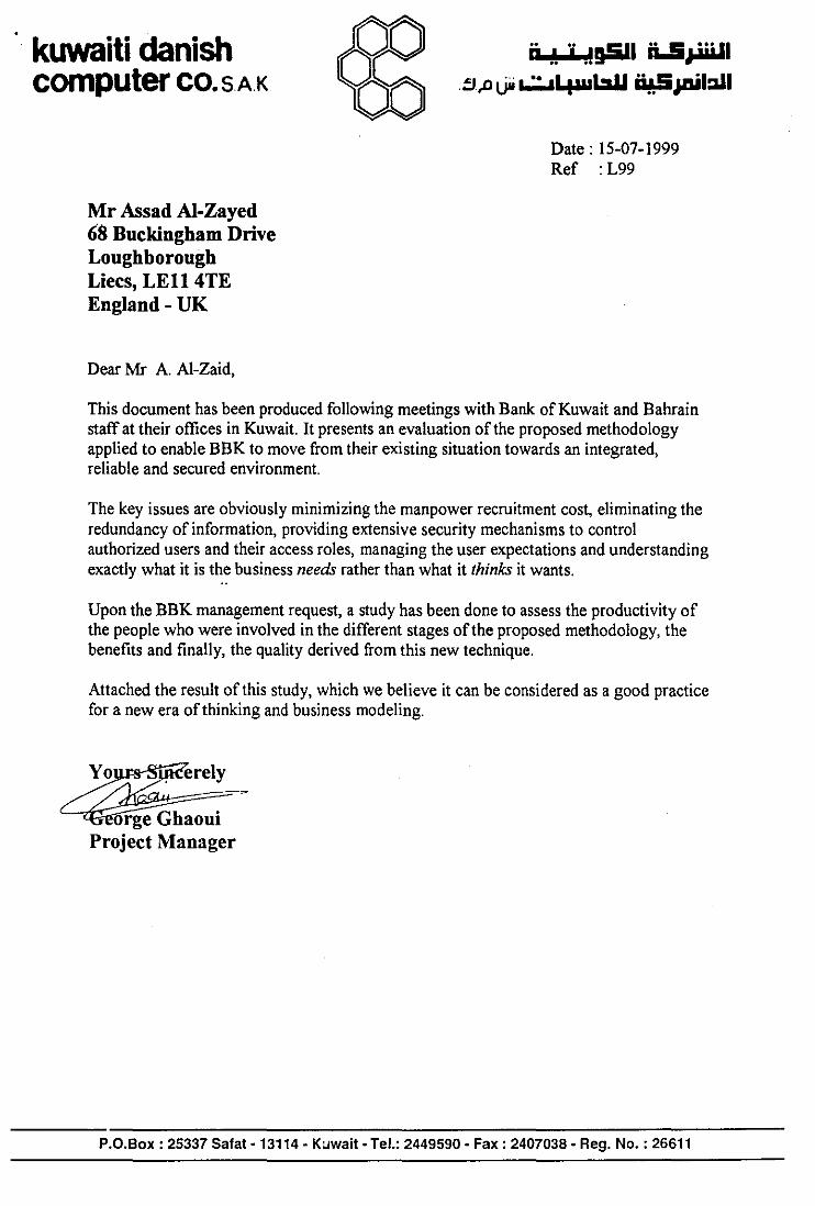
kuwaiti danish computer co. SAK
Mr Assad Al-Zayed 68 Buckingham Drive Loughborough Liecs, LEll 4TE England- UK
Dear Mr A. A1-Zaid,
;; ,\ 'j .!g5Il iUi ...... 1 !I,D Uii ~4aabU i¥.SJDiI:ll1
Date: 15-07-1999 Ref : L99
This document has been produced following meetings with Bank of Kuwait and Bahrain staff at their offices in Kuwait. It presents an evaluation of the proposed methodology applied to enable BBK to move from their existing situation towards an integrated, reliable and secured environment.
The key issues are obviously minimizing the manpower recruitment cost, eliminating the redundancy of information, providing extensive security mechanisms to control authorized users and their access roles, managing the user expectations and understanding exactly what it is the business needs rather than what it thinks it wants.
Upon the BBK management request, a study has been done to assess the productivity of the people who were involved in the different stages of the proposed methodology, the benefits and finally, the quality derived from this new technique.
Attached the result of this study, which we believe it can be considered as a good practice for a new era of thinking and business modeling.
orge Ghaoui Project Manager
P.D.Box : 25337 Safat - 13114 - Kuwait· Tel.: 2449590 • Fax: 2407038· Reg. No. : 26611

kuwaiti danish computer co. SAK
Stage I : Change Analysis
;; ., .j .!D5JI ii..!i~1 .!J ...•• I •• "L:aII ii&.S uti 1:111 ,DU" L.,;,;.,I..,.. ..,-
The points that I think very effective at this stage are as follows
- The suggested combination of workshops and meetings provides the opportunity to define the gap and duplication as well as potential future process improvements.
- The business problems of the Human Resources Division (HRD) were analyzed in a very clear and effective way.
- The cross reference matrix between groups and business process shows the ideal usage of data by process.
- The proposed methodology defines in a clear way the organization structure, the scope of the system and its relationship with the internal and external actors.
- The model techniques defines clearly the tasks of each person, the relationship with his environment and eliminates the conflict between the different
divisions and departments.
- The suggested methodology manages the transactional as well as informational needs of the bank.
Although, a lot ofHRD functions' has been analyzed by the proposed methodology some other functions are not, such as employees over time, type ofleave or absents, etc.
Stage 11 : System Modelling
- The list of measurements which has been defined during this stage in order to start the package evaluation process and choose the cost/effective solution are very effective and satisfactory.
- The way of defining the problems that are introduced when applying a new alternative package and then presenting these problems to the users is very effective and important.
- Also, evaluating the impact of the new system changes on the BBK's Human Resources Division before implementation is a highly recommended process and very effective.
P.O.Box : 25337 Safat· 13114 • Kuwait· Tel.: 2449590· Fax: 2407038· Reg. No. : 26611

kuwaiti danish computer co. S AK
;; .\ 'j .!§SII ii..5,JoiiiJI B,D LJii "'::"4wb.U ii!S~I~1
Stage III : Socio-Technical
Testing Strategy
T", Data
Live
Data
In this section , I have included some extracts from our own methodology and compared this against the testing practices that have not been well defined by the proposed methodology.
In order to fully understand this section of the report and our Testing Strategy it is necessary to understand the proposed Configuration Management rules that we advocate. Briefly this is that there should be four environments or areas. These are shown in diagrammatic form below.
Development Environment < ~~m~'~
~
LinklSystcst Environment >
~ > Errors Promote
and .. luucs
Acceptance Environment .> .
~~mo,,~
Production Environment >
The Proposed methodology currently uses 3 environments:
• A development area
• AQAarea
• A production area
we do not consider that this is adequate.
P.O.Box : 25337 Safat· 13114· Kuwait· lel.: 2449590· Fax: 2407038· Reg. No. : 26611

kuwaiti danish computer co. S AK
Unit Testing
;; .! 'j .!;5I1 ii.5,.,iii.1I B,lllJii ~4aubU ~JDiI:JJ1
Currently when a programmer has developed a new program, or made changes to an existing program he runs tests against this new version of the program in the development environment. There is no evidence that these tests are carried out in a structured manner, i.e. that there are any test packs, test scripts, expected results or comparison between the actual results and the expected results.
Below is an extract from our standards which shows the process that we recommend to be adopted for Unit Testing.
Detailed Unit Test Process
11. Complete Configuration Management Form
1. Review Program Spec
10. Sign off SUccessful Tests
9, Check Actual Results against Expected
8. Record Actual Test Results
7. Run Tests
6. Load Test Oatabases
2. Define all Test Conditions
3. Approve Unit Test SpeCification
4. Set up Empty Test Data Bases
5. Specify Test Data Base Records
Actions 5 through 9 are repeated several times for each Program or Module
System Testing
Currently, when the programmer has completed his testing the Section Head promotes the program into the QA environment and performs some testing on the overall system. Again, there is no evidence that there is any structure planning in this testing.
Below we show an extract from our standard which addresses the System Testing phase of testing
P.D.Box: 25337 Safat ·13114· Kuwait· Tel.: 2449590· Fax: 2407038· Reg. No.: 26611

kuwaiti danish computer co. SAK
0°0 00
Detailed System Test Process
11, Complete Configuration ManagementFonn
10. Sign oH Successful Tests
9. Check Actual ResuHs against Expected
B. Record Actual Test Results
7. Run Tests
6. Organise People
;; " 'j .!~I ii.5,1olW1 .!J,D Uii ~LpaabIJ ~JAiI:l.l1
1. Prepare Outline System Test Plan
2. Define all Test Conditions
3. Define Data Detail & Expected ResuHs
4. Review & Approve System Test Spec
5. Set up Infrastructure
Actions 6 through 9 are repeated several times for each System
Acceptance Testing
This is the stage of testing where the users become involved and it is where they formally agree to accept the new/changed system. Currently, this is performed in the QA environment (we recommend that it be performed in a separate environment).
The Acceptance Testing stage should additionally cover some of these aspects that are of particular importance to the user community and will, in addition, cover specific aspects of the system in which the user community is particularly interested. This will typically include:
• effect of the system going down during processing
• successful recovery from back ups
• fall back procedures and provision of minimum facilities
• security aspects, testing access restrictions and privileges
• volume testing
• interfaces to and from external systems
• conversion routines from existing systems
P.O.Box : 25337 Safat - 13114 - Kuwait - Tel.: 2449590 - Fax: 2407038 - Reg. No. : 26611

kuwaiti danish computer co. SAK
ji .\ "j .!D5II ii..5.,.wJ1 .tJ,Jl UM ~4AabU i¥.5Ja.iI:1.l1
Below is an extract from our standards dealing with Acceptance testing.
Detailed Acceptance Test Process
11. Complete Configuration Management Fonn
10. Sign 011 SUccessful Tests
9. Check Actual Results against Expected
8. Record Actual Test Results
7. Run Tests
6. Organise People
1. Prepare Outlin. Acceptance Test Plan
2. Define all Test Conditions
3. Define Data Detail & Expected Results
4. Review & Approve Acceptance Test Spec
5. Set up Infrastructure
Actions 6 through 9 are repeated several times for each System
P.O.Box : 25337 Safat· 13114· Kuwait· Tel.: 2449590· Fax: 2407038· Reg. No. : 26611

Appendix 3 Published Paper

READ-IT: A Methodology for Requirements E,licitation and Analysis for the Development of I.I.
Abstract
Systems
Asad AI-Zaid and Ray Dawson
Dept. of Computer Science, Loughborough University,
Loughborough, Leics. LE11 3TU, UK
TeI. +(44) 1509-228226, Fax. +(44) 1509211586 Email: [email protected]
An important stage in software engineering IS the analysis of the system
requirements. Systems have been known to fail because the requirements analysis has
concentrated only on the technical problems without taking into account the change
implications for the users and the organisation. In this paper a new methodology is
described for requirement elicit at ion within the context of an organisation. It focuses
on the representation of user and organisational requirements in the design of a socio
technical system with the aim of ensuring the users "own" the system designed and
that the organisational change implications are fully understood and taken into
account. The new methodology is illustrated in a case study at an international bank
and is shown to be effective in fully capturing the requirements of a working
organisation.
Introduction
There have been a number of high profile cases of IT system failure that have been
attributed to a poor understanding of how the new system will require changes in the
organisation's structure and the users roles within this structure (eg. the London
Ambulance Service [1 D. Furthermore, it is the authors' experience that unless the
1

users are involved in the design so that they can feel they "own" the new system, they
will not have the same desire to make it work. The requirement elicitation process is a
social process, which aims at creating communication channels between the client
imd the system developers that will continue throughout the project life cycle.
The authors of this paper have examined different requirements methodologies to find
a means of ensuring that requirements elicitation will fully identify the organisational
and individual user requirements, and that any new system proposed will take into
account the changes implied for both the organisation and the individuals. A full
report of this review is beyond the scope of this paper, but no one methodology was
discovered that would fully satisfy both the user and organisation needs. Two
methodologies stood out, however: ISAC [2,3] because its analysis involved the
participation of the users themselves, and ORDIT [5,6] because it was the only
methodology found that attempts to capture the change needs of an organisation.
A new methodology has, therefore, been developed for the identification and
elicitation of user and organisational requirements known as READ-IT
(Requirements Elicitation and Analysis for the Development of IT systems). This is
based on the two existing methodologies, ISAC and ORDIT, combined in a
complementary fashion addressing itself in a homogeneous way to the entire analysis
and design section of the information system life cycle. Combining ISAC's strength
of user involvement in problem identification and business analysis with ORDIT's
strength in capturing organisational requirements using responsibility modelling, a
new and more effective methodology is formed.
ISAC
ISAC (Information Systems Work and Analysis of Change) is a methodology for the
analysis and design of information systems that makes extensive use of graphics as a
working tool during the design process and as a design product presentation device.
The ISAC methodology is very strong in "Change Analysis" in the early stages of
system design. It employs the users themselves to model the existing and proposed
systems. However, the activity model, which is used throughout the methodology, is
2

insufficient for addressing some of the essential elements of system development
such as organisational issues, non-functional requirements and socio-technical
aspects.
ISAC is explained in more detail in literatures by Lundeberg [2,3]. Through
experiments and case studies the authors of ISAC have proved that the methodology
can help in the user requirement definition process when used in the software
development life cycle [4]. The strength of ISAC lies in its intensive user
participation, and the early identification of the business strategy and the business
mission, which occurs mainly in the change analysis stage in ISAC.
ORDIT
ORDIT [5,6] is a methodology that uses the socio-technical approach when designing
a system. It concentrates on the interaction between people and IT within the
organisation as part of the system. One of the its main objectives is to elicit the
organisational requirements which comes out of a system being placed in the social
context rather than those requirements which are taken from the tasks to be performed
or the functions to be supported. ORDIT uses an enterprise modelling language as the
main tool of the methodology with an essential component being the responsibility
model for modelling the organisation and its systems. The ORDIT philosophy is to . model the responsibilities in the organisation to reveal, firstly, the functions of the
organisation which are presented in the responsibility held by agent entities, and
secondly, the structure of the organisation which is presented in the responsibility
relationship between them.
Why the Responsibility Model?
The responsibility model is adopted for the READ-IT methodology, rather than other
modelling tools such as the activity model used in ISAC, for the following reasons:
1. Using the responsibility model, it is possible to define the organisational structure
through the structural relationship between agents. The structural relationship
3

defines the value and nature of the relationship between agents. For example, the
peer to peer relationship between two agents tell us that there is no power of one
over the other and these two agents have to work together and negotiate in order
to reach a decision. Figure 2 has an example of this relationship.
The activity model used in ISAC methodology does not allow us to define the
nature of the relationship between agents and is insufficient for exploring the
nature of the relationship between the borrowing and reservation agents.
2. Using the responsibility model it is possible to define the policy of the
organisation through the structural relationships between agents.
3. Using the responsibility model it is possible to identify requirements at different
levels of the organisation. At the agency level which is the highest level in the
organisation the requirements are concerned with policies; at an individual level
the requirements are concerned with making work easier. At the intermediary
level, which 'is the role level, requirements are concerned with how the
organisation itself functions and what obligations and capability tokens are
necessary to support this.
Other models cannot define the organisational requirement at different levels.
4. Using the responsibility model helps in providing an overview of the stakeholders'
role without initially going into a tremendous level of detail. Figure 1 defines all
the stakeholders' roles that will be affected by introducing the new system to a
division of an international bank. For example, the role of the advertising agency
is to provide public awareness of the jobs available at the bank, the role of the job
agency is to select the most suitable candidate for each job and so on. The model
gives an overall clear representation of what is going on at a higher level.
5. The responsibility model is not difficult to understand and can be used by
representatives within the organisation as well as the systems analyst.
4
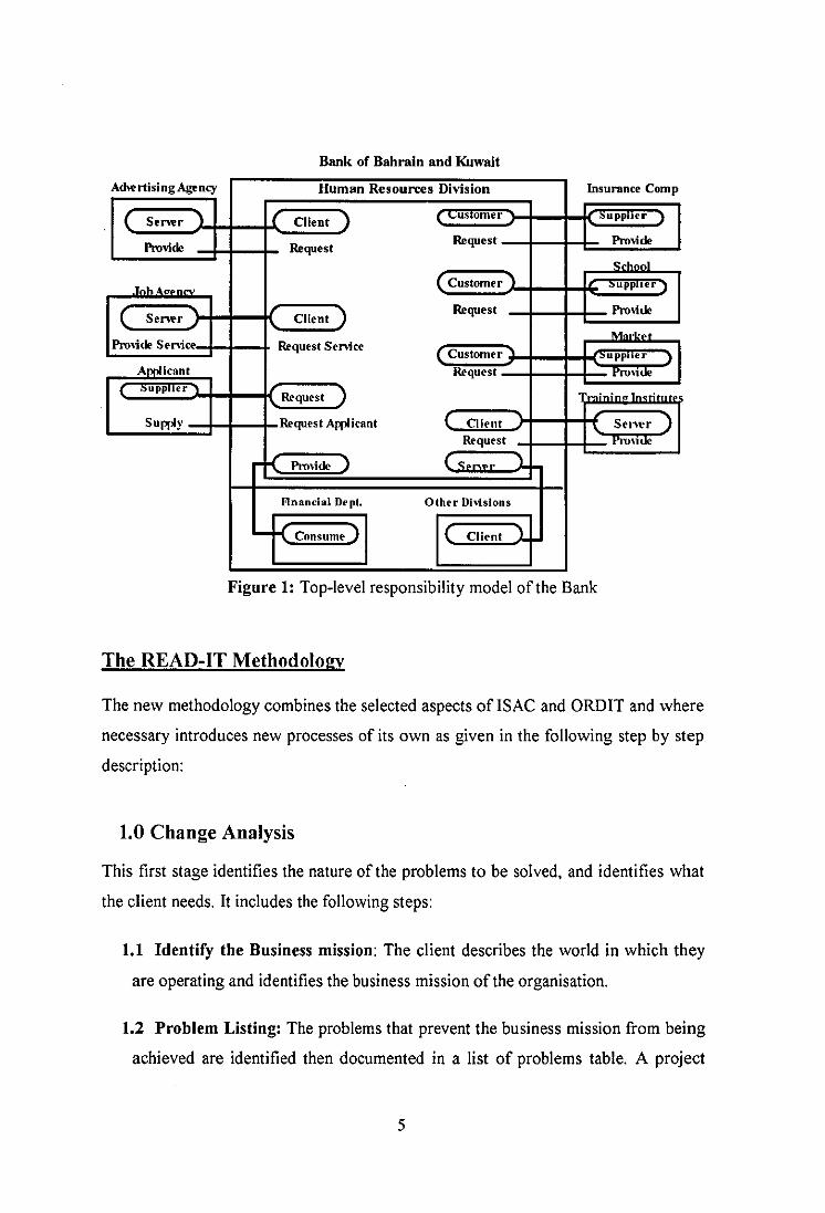
Bank of Bahrain and Kuwait
AdwrtisingAgency ~ .. .,.u .. Insurance Comp
( Se..,.r 1 I ( aient ) ( . >.pp"" )
Pro-;OO Request Request Pro-;OO
School
.Tnh. ( ) ]
( Se..,.r Client ) Request Pro-;OO
M ...... 1'1"0-;00 ~. Request Se-nice
( lOU""".. J
~ t'rO\1oe
) -,.
Supply ,- Applicant ( Client \. Sc,wr ) "1"I"j<le
1'I"O,iOO ) lS .. wr J.
Flnancial Dept. Other Divisions
.... K ) l Client 1
Figure 1: Top-level responsibility model of the Bank
The READ-IT Methodology
The new methodology combines the selected aspects oflSAe and ORDIT and where
necessary introduces new processes of its own as given in the following step by step
description:
1.0 Change Analysis
This first stage identifies the nature of the problems to be solved, and identifies what
the client needs. It includes the following steps:
1.1 Identify the Business mission: The client describes the world in which they
are operating and identifies the business mission of the organisation.
1.2 Problem Listing: The problems that prevent the business mission from being
achieved are identified then documented in a list of problems table. A project
5

group is formed, consisting of representatives from all the stakeholder and user
groups affected. These problems are presented to the project group who, in turn,
take the problems to their own department groups in order to generate feedback.
1.3 List of Problem Owners: Problems are usually related to the viewpoints of
the participants in the system, so this step identifies which problems affect which
group of users or stakeholders.
1.4 Cause-Effect Analysis: After getting agreement on the identified problems a
cause-effect analysis for each problem is performed with the help of the analyst.
This can reveal yet more problems and so the problem and owner lists are
updated.
1.5 Quantifying the Problems Identified: Each problem is then quantified to
enable the project team to decide whether to invest in the solution process.
1.6 Model the. Current System: Modelling the current system of the organisation
can be used as a platform for generating and discussing alternative solutions and
represent the current understanding of the socio-technical system by producing
various sets of models. Modelling the current system helps the analyst to
determine the boundaries around the system under development. To understand
the purpose and structure of the organisation, the current system is decomposed
into its sub-components, to explore and draw the implications of the
organisation's structure. Modelling the current system will also help elicit user
requirements by generating feedback that can then be applied to adjust the model.
This process will help in generating and discussing alternative solutions and in
the understanding of how responsibilities and authorities in the organisation are
going to change as a result of introducing the new system.
1. 7 Identify New System Goals (Change Needs): The project group specifies the
goals to evaluate any solution proposal. It is recommended at this stage to make
goals as general as possible to achieve agreement between the problem owners.
For each goal specified, the problems that prevent it from being achieved are
6

identified. The benefit is two fold, (1) to compare what is wanted (the goal) with
what is available (the problem), and (2) to accomplish each goal by trying to
solve its related problems. For each project goal a list is made of the problems to
be solved and the objectives that the change should help achieve.
1.8 Generate a List of Change Alternatives: All ideas of change alternatives are
written down (brainstorming) in order to be evaluated and the most suitable
alternative for the organisation agreed with the problem owners. In addition, all
user and organisational requirements are finalised at this stage so they can be
discussed and included in the final solution. The alternatives are presented to the
problem owners in natural language form to obtain agreement on the future
system and how the deficits in the current system should be overcome.
Discussion of the alternatives will also identify any conflicts of requirements,
particularly in definitions of boundary objects and organisational impact.
Second Stage
2.0 Modelling the New System:
User requirements and priority ordering are considered at this stage in order to
generate possible design options for the socio-technical system. The sponsor and
problem owners have to choose the most suitable package for the organisation with
the help of the analyst/facilitator when needed. The steps in this stage are as follows:
2.1 Evaluate Each Alternative Solution: Each alternative solution is
investigated to see which problems the proposed solution resolves. To produce
this, for each solution alternative a matrix of problems against problem owners has
to be constructed showing which problems are solved and which remain.
2.2 Select the Best Alternative: The sponsor is presented with a report on the
evaluated alternatives so a choice can be made. The problem solver can suggest a
choice but it is important that the sponsor authorises this choice.
7

2.3 Pre-Implementation Impact Analysis: This is a new process, which is not
included in either ORDIT or ISAC. The benefit of this process is to evaluate the
impact of the new changes of the chosen packages on the organisation. If the
chosen new package is too costly or too disruptive to the current system then the
sponsor or problem owners might reject it. This process is necessary to save time
and effort in the later stages of the development life cycle as a project may be
abandoned if the impact of the changes is too disruptive or there is insufficient
money to complete the project. The system analyst has to perform this process to
be aware of the situation and, where necessary, to go back and alter the proposed
changes to be acceptable. This process is repeated until the problem owners and
sponsor accepts one of the proposed solutions.
Case Study
The Human Resources Division (HRD) in an international bank in Kuwait needed to
expand its IT system in order to compete with the high demand for the bank's
resources. A study was undertaken to help the Division get a more efficient system for
their administration. The role of the READ-IT methodology was to capture the user
and organisational requirements for the proposed system, identify the current problems
and suggest solutions for the future.
The HRD provides a wide range of services to the bank. The division consists of four
departments namely, Recruitment, Compensation, Personnel & Training and Career
Development. The Recruitment department consists of three sections namely,
Security, Dispatch and Archive. Each department has its own staff, and own activities
and routine performed using a mixture of manual and computer supported procedures.
The computer facilities were a mixture of small networks and stand alone PCs.
The first meeting was established between the bank's sponsors and the system analyst
to obtain a description of the organisation and how it operates. The result of this
discussion was an agreement to focus on current problems of the HRD systems.
Meetings were then held with the HRD to identify in more detail the problems of the
current system. A list of problems was created which, for example, included
8

information provided by some HRD departments not being up-to-date, and different
departments using different report layouts and presentation styles.
The users that were affected by these problems were identified and documented in a
table of problems against problem owners. The project group members were chosen as
representatives of the different groups of problem owners identified. The members
were mostly from middle management with decision making responsibilities. The
project group then performed the cause-effect analysis. Through this process more
problems were discovered and the list of problems were updated accordingly. A
quantitative study of the severity of the problems enabled the decision of whether to
invest in the solution process or not.
Once the problems of HRD were established, it was possible to determine the
boundaries of each problem by identifying those stakeholders or agencies within and
outside the HRD system (see Figure 2). Only the agencies or departments within the
boundaries of the problem were looked at in more detail. For each department within
the HRD all responsibilities and its associated obligations were listed. This helped
identify the existing policy implemented within HRD.
The next step was to model the current system of the HRD using the responsibility
model. This model helped elicit information about the role and function of HRD
within the bank, the force for change, and issues and perspectives to be adapted. The
responsibility model in Figure 2 acted as the platform for generating and discussing
alternative solutions.
In the pre-implementation impact analysis step, the impact of the new changes on the
current system were studied and evaluated by the sponsors and stakeholders of the
bank. All changes suggested to the current system of HRD were accepted and so the
new system was modelled.
9

dvenlsement Agency
International Bank Human Resources Division
[tdieal [n~urante r;==~l Advert!. ng
~(~'~'~~"~)!I~fnfu~~----~~~ ~~~~ __ ~It'iUl'antt Comnoonv , foH'ProVld.,:)
Appll cation andldat
I (Provider r ~
JobAl':encin -"-' Candiu' u
I ( 5tnfr )-~ Oient)
Requnt)
Pro\'ider )
School School r.::==:::i
~~)j----hKf. ... JLH'ProVid" )
Salarv Market
~"I',i :;) lPrO\'idtr Request
Con~ume T$"'I'L r- Consume.l f -,
\'a anty r- Pro\ider I ~=~~";!"_~n~o .....,., Fm~ YH-In!::/ ('pt dents training and
Si ned ~ nro pennnntl l? DHeiopnltnt
I [co -;;tract (Pro\'ider} le" Supplitr )-
,-_ .... r--:e ta (Contum) Provider)
( Peer
I( Accept
Training
Peer
Financial Dh'ision
Con5umf~
~,n 1-------'
Coune Training (oordination Institute
~f{Scmr)
Figure 2: Responsibility model of the bank future system
10
Figure 2 shows the restructuring of the existing system and the realignment of
responsibilities when adopting the new system. For example, the Personnel
department now has to make available to the Compensation department the employee
itiformation needed in order to update the employee dependent records. This is
described in the Provide-Consume relationship between the Personnel and the
Compensation departments. In the old system the compensation department used to
depend on the existing information held in other divisions and the honesty of
employees.
From modelling the new system, all the new responsibilities were identified and
documented.
This case study is on-going, the proposed new system is currently being considered by
the bank who have passed the analysis findings on to independent consultants to
review and carry forward to the implementation stage. However, the feedback from the
bank employees so far is that they feel a great deal has already been achieved as they
have greatly increased their understanding of their processes and problems, and that a
realistic, workable solution has been identified as a way forward.
Advantages of the READ-IT Methodology Shown by the Case Study
The first stage of the new methodology concentrated on the importance of people (end
users, managers, and funders) and their problems in the organisation. This process
helped identify the fundamental causes of the users' problems in the existing HRD
system, specifying the changes that need to be made and giving alternative solutions.
In addition, the new methodology enabled the users to carry out the problem analysis
themselves by providing them with a series of easy tools, tables and method steps. For
example, the problem tables were distributed to different levels of the bank problem
owners (executive managers, middle managers, and lower end users) to be filled out
by them to fully capture their requirements. Tools such as the cause effect graphs were
understood by all levels of problem owners in the bank organisation. The feedback
11

from these problem owners concerning these tools is that the tools are easy to use and
understand. This shows that these tools enable the problem solver to share a common
language with the problem owners enabling a more effective e[icitation and capture of
their requirements
The READ-IT methodology involves devoting time to identifying the users' problems
and needs in the first stage. The advantages of this were found to be:
• It gives the users a better understanding of their own organisation before
implementing any changes. In the bank case study, this was done by letting the
bank problem owners discuss their problems and analyse their work themselves
assisted by a series of easy tools and methods.
• It supports the communications process between the users and analyst making
sure they talk the same language. In the bank case study, it was not possible for
the problem owners to understand what was happening in the development
process until all the tools and techniques were explained and illustrated. This
common language then made it easier for the analyst and problem owner to
understand each other.
• It gives the analyst and users a better understanding of the users' requirements.
In the bank case study, a large proportion of the available time was spent on
identifying user needs and objectives with much negotiation and compromise
between the bank problem owners themselves facilitated by the system analyst.
• The greater understanding of user and organisational needs leads to fewer and
more manageable problems in the later stages of the system development and
may avoid the system failing altogether.
The feedback of the bank users concerning the various meetings was that they felt
tired of attending these meeting but then, on the other hand, they felt they had never
understood the organisation and their work as much as they did afterwards.
12

Listing the needs and goals of HRD in tables and trying to solve the problems that
prevent these goals from being achieved enabled the analyst to identify the business
strategy of HRD and determine what the new system should provide for the bank in
the future. This is an aspect ofISAC adopted in the new methodology.
In the modelling stage the responsibility model was adopted from the ORDIT
methodology. This helped to identify the organisational issues and needs in the
second stage. Through the process of listing the responsibilities and obligations for
each department in the Human Resources Division it was possible to determine the
division's main policies. In the same manner, through listing the roles of agents in
each department, it was possible to identify the job descriptions of the division
employees. Also, using the responsibility model it was possible to identify the
realignment of the organisation structure necessary to meet the users' requirements.
This analysis proves the value of addressing the organisational issues and needs. The
bank responsibility model in Figure 2 provides a rich picture of the environment as
well as the roles ·of agents, information flow, the structural relationships and the
utilisation of resources in the bank. This model was constructed through an iterative
meeting process between the analyst and the problem owners. The feedback from the
problem owners at the end of this process was that, as with the tables and methods,
they also found these models easy to use and understand.
Conclusion
This paper presents a new methodology, READ-IT, which is based on the
combination ofISAC and ORDIT methodologies extended with an additional original
processes, the pre-implementation impact analysis. The stronger factors of ISAC and
ORDIT form the foundation for the new methodology, which is effective in
identifying and eliciting the user and organisational requirements.
A project team of stakeholder representatives was necessary to capture and elicit
requirements throughout the bank project. There are three main actors of the project
team namely: the problem analyst, problem owners, and sponsor or stakeholders. The
process of communication between them may be regarded as a negotiation process,
13

where potential problem owners of the system explore and fully understand the
requirements, agreeing on what they want and what they need, while the problem
analyst becomes confident that they are solving the right problem. As McKeen [7]
stated "users and developers will benefit from close interaction by exchanging views,
identifying, and resolving conflicts as well as sharing information necessary to
effectively accomplish the task."
The READ-IT methodology follows a form of iterative process where the users of the
system participate in meetings and discussions held at different times. Through these
meetings, tables and modelling languages are used to record and document all
generated ideas. The facilitator (the analyst) acts as a chairperson of the meeting and
has a critical role in organising the work of the requirement negotiation team. After
each meeting, each member of the project team meets with his department groups to
discuss all new ideas and to generate feedback for the next project team meeting.
The new methodology also encourages partnership between the problem owners,
sponsor and project team members to validate everyone's understanding of the
information gathered, especially in new system changes. This supports the
requirement definition process, as Koltsblatt and Beyer [8] concluded, it is about
people talking effectively to each other.
The processes of helping the problem owners to develop their own models of the
required system reveals that the transfer of problem owners understanding of business
practice to the problem analyst is the key to effective communication benefiting both
parties. This, and the understanding of the organisational issues obtained from the
responsibility modelling has been shown to make the READ-IT methodology very
effective in fully capturing the organisational and individual requirements of a
working environment.
14

References
1) L.A.S. (1993), "Report of the Inquiry into the London Ambulance Services".
London Ambulance Services, London
2) Lundeberg, M. (1981), "Information System Development A Systematic
Approach", Prentice Hal1 Inc., Englewood Cliffs, NJ.
3) Lundeberg, M. (1982), "The ISAC Approach to Specification", in Information
Systems Design Methodologies: Improving on Practice, North Hol1and Press.
4) Wrycza, S. (1990), "The ISAC-Driven Transition Between Requirements Analysis
and ER Conceptual Modelling", Information System, V.15, No.6, pp. 603-614.
5) Blyth, AJ.C, (1995), "Enterprise Modelling and its Application to Organisational
Requirements, Capture and Definition", Ph.D. Thesis, Newcastle University.
6) Dobson, J. (1993), "Organisational Requirements Definition for Information
Technology System", Theory, Use and Integrative Aspect ofIS Methodology,
Conf 1993, British Computer Society, pp. 295-308.
7) Mckeen, J.D., Guimaraes, T., and Wetherbe, CJ. (1994). The relationship between
User Participation and User Satisfaction: An Investigation of Four Contingency
Factors, User Participation and Satisfaction, MIS Quarterly, PP. 427-447.
8) Koltzblatt, K and Beyer, H.R (1995). Requirements Gathering: The Human Factor,
Communication of ACM, vo1.38, No. 5, PP. 30-32.
IS


r 1
r 1
r 1
r 1
rl
Recommended