8/8/2019 A Method for Evaluating the Heat and Mass Transfer
http://slidepdf.com/reader/full/a-method-for-evaluating-the-heat-and-mass-transfer 1/10
A method for evaluating the heat and mass transfercharacteristics in a reversibly used water cooling tower
(RUWCT) for heat recovery
Kunxiong Tan, Shiming Deng*
Department of Building Services Engineering, The Hong Kong Polytechnic University, Kowloon, Hong Kong SAR, China
Received 1 April 2000; received in revised form 27 March 2001; accepted 4 April 2001
Abstract
In sub-tropical regions, a standard water cooling tower may be reversibly used, as part of a desuperheater heat
recovery system for service hot water heating, to extract free heat from ambient air in colder seasons when building
cooling load is reduced. Chilled water is pumped into a reversibly used water cooling tower (RUWCT) where it is
heated by warmer ambient moist air. This paper presents a method by which the heat and mass transfer characteristics
in a counter-flow RUWCT can be evaluated. The method is developed by introducing to the Merkel’s equation for
standard water cooling towers the revisions that account for the differences in heat and mass transfer characteristics
between a water cooling tower and a RUWCT. Field experimental results from a RUWCT installed in a sub-tropical
region in China indicated that the method developed could be used to evaluate the thermal performance of a RUWCT
with an acceptable accuracy. # 2002 Elsevier Science Ltd and IIR. All rights reserved.
Keywords: Cooling tower; Mass transfer; Heat transfe; Calculation; Cooling; Heating; Reversible
Me ´ thode permettant d’e ´ valuer les caracte ´ ristiques de transfert
de chaleur et de masse dans une tour de refroidissement d’eau
utilise ´ e e ´ galement pour le chauffage d’eau
Re ´ sume ´
Dans les re gions subtropicales, on peut utiliser les tours de refroidissement de facon re versible pour fournir de l’eau
chaude sanitaire et pour extraire de la chaleur de l’air ambiant pendant les saisons les plus fraıˆches afin de re´ duire la charge
thermique d’immeubles. On apporte de l’eau refroidie par pompage a ` la tour de refroidissement re versible (RUWCT) ou `
cette eau est alors chauffe e a ` l’aide de l’air humide ambiant plus chaud. Cet article pre sente une me thode permettantd’e valuer les caracte ristiques de transfert de chaleur et de masse dans une RUWCT a ` e coulement a ` contre-courant. Les
auteurs ont de veloppe la me thode a ` l’aide de l’e quation de Merkel, en introduisant, pour les tours de refroidissement
classiques, des modifications tenant compte des diffe rences entre les caracte ristiques de transfert de chaleur et de masse
entre une tour de refroidissement et une RUWCT. Les re sultats obtenus sur le terrain avec une RUWCT installe e dans
une re gion subtropicale chinoise indiquent que la me thode de veloppe e pourrait eˆtre utilise e afin d’e valuer la performance
thermique d’une RUWCT avec une pre cision acceptable.# 2002 Elsevier Science Ltd and IIR. All rights reserved.
Mots cle s : Tour de refroidissement d’eau atmosphe ´ rique ; Transfert de masse ; Transfert de chaleur ; Calcul ; Refroidissement ;
Chauffage ; Re ´ versibilite ´
0140-7007/02/$22.00 # 2002 Elsevier Science Ltd and IIR. All rights reserved.
P I I : S 0 1 4 0 - 7 0 0 7 ( 0 1 ) 0 0 0 4 4 - 5
International Journal of Refrigeration 25 (2002) 552–561
www.elsevier.com/locate/ijrefrig
* Corresponding author. Fax: +852-2774-6146.
E-mail addresses: [email protected] (S. Deng).

8/8/2019 A Method for Evaluating the Heat and Mass Transfer
http://slidepdf.com/reader/full/a-method-for-evaluating-the-heat-and-mass-transfer 2/10
1. Introduction
Using desuperheaters to recover heat from central
water chiller plants of building air-conditioning systems
to generate service hot water might be possible in both
the tropics and subtropics. However, in sub-tropical
regions during colder seasons, there may not be suffi-
cient heat to be recovered from buildings due to reduced
building cooling load. In order to provide year-round
service hot water supply, backup water heating pro-
visions, normally by electricity, are required. Given that
in the subtropics in winter, ambient air temperature isnormally at around 15C, a standard water cooling
tower may be operated to extract heat from ambient air
as a heat source for water heating in a desuperheater
heat recovery system. Part of chilled water produced in
the chiller plant for air-conditioning at, say, 7C is
pumped to the tower where the water is heated by
ambient air to, say, 12C. Since in colder seasons, an
air-conditioning system is normally operated in part
load condition, so that an existing water cooling tower
which might be idle can be used as a RUWCT. This is
cost-effective as no additional cost for a water cooling
tower is required.
This paper presents a method by which the heat and
mass transfer characteristics in a counter-flow RUWCT
can be evaluated. Three major differences in the heat
and mass transfer processes between a standard water
cooling tower and a RUWCT have been identified. The
method has been developed by introducing to the Mer-
kel’s equation for water cooling towers the revisions that
account for these identified differences. Field experi-
mental results from a RUWCT installed in a sub-tropical
region in China indicated that the method developed
could be used to evaluate the thermal performance of
RUWCT with an acceptable accuracy.
2. Background
Until recently the performance of counter-flow water
cooling towers was evaluated using the so-called Merkel
model [1]. The heat and mass transfer process taking
place in a RUWCT, where water is heated and air is
cooled, is, however, opposite to that in a standard water
cooling tower. A RUWCT may be considered to operate
in a similar way to a spray room or an air washer where
air is cooled and dehumidified. A number of earlier
Nomenclature
am Surface area per unit tower volume for mass
transfer (m2/m3)
C Constant in Eq. (10)
CMS Humid air flow rate (m3/s)C a Specific heat of humid air (kJ/kgC)
C w Specific heat of water (kJ/kgC)
F Correction factor for the change of chilled
water flow rate
G Dry air flow rate (kg/s)
H Fill height (m)
h Air enthalpy (kJ/kg dry air)
hv Enthalpy of saturated water vapor at water
temperature tw (kJ/kg)
hw Enthalpy of water at water temperature tw (kJ/
kg), hw=C w (twÀtref )ffiC wtw
m Mass flux (kg/m
2
s)L Chilled water flow rate (kg/s)
QT Total heat transfer rate (kW)
Qb Latent heat transfer rate (kW)
QA Measured total heat exchange capacity (kW)
QA0 Calculated total heat exchange capacity (kW)
r0 Latent heat of water at the reference
temperature tref (kJ/kg)
tw Chilled water temperature (C)
ta Humid air temperature at a level where water
temperature is tw (C)
tdb Dry-bulb temperature of humid air (C)
twb Wet-bulb temperature of humid air (C)
tref Reference temperature for 0 enthalpy of air
and water (C), tref ffi 0.01C
tw,n Measured outlet chilled water temperature
(C)tw,n
0 Calculated outlet chilled water temperature
(C)
V Tower volume (m3)
w Air humidity ratio (kg/kg dry air)
XN Constant in Eq. (10)
Heat transfer coefficient for air film (kW/m2
C)
Mass transfer coefficient for air film (waÀ wi)
(kg/m2 s)
Á Difference in Table 1 and Table A1
Ratio of latent heat transfer to the total heat
transfer
Subscripts
0 State of water and air entering a RUWCT
a Humid air
dew Dew-point
i Interface
n States of water and air leaving a tower
s Saturated
w Water
K. Tan, S. Deng / International Journal of Refrigeration 25 (2002) 552–561 553

8/8/2019 A Method for Evaluating the Heat and Mass Transfer
http://slidepdf.com/reader/full/a-method-for-evaluating-the-heat-and-mass-transfer 3/10
studies on standard water cooling towers indicated that
the calculation methodologies for cooling towers proved
valid for the analysis of heat and mass transfer in spray
rooms or air washers. For example, it is stated by
Threlkeld that the governing Equation of a counter-flow
spray dehumidifier can be derived in a manner analo-
gous to a cooling tower [2]. Also, as pointed out bySutherland, the analysis and solution of cooling towers
can be extended to describing the thermal behavior of
chilled spray dehumidifiers [3]. However, the heat and
mass transfer process in a RUWCT has been identified
to be different from that in either a standard water
cooling tower or a spray room.
2.1. A RUWCT vs a standard water cooling tower
Three major differences in the heat and mass transfer
processes taking place in a RUWCT and a standard
water cooling tower have been identified, as follows.
2.1.1. Water-side heat transfer resistance
Previous research work on water cooling towers indi-
cated that the water-side heat transfer resistance in a
water cooling process is small and therefore negligible.
Ibrahim et al. provided a model to investigate the effect of
tower parameters on air and water temperature distribu-
tion across air and water film thickness [4]. The results
showed that water-film thermal resistance only caused a
very small reduction in the interface water temperature
and had no significant effect on the water-side Nusselt
number. Gurney et al. concluded that ignoring water-film
resistance would not affect the accuracy of results in gen-
eral refrigeration and air-conditioning calculations [5].
Because water-film resistance is negligible in the ana-
lysis for a standard water cooling tower, a water cooling
process is primarily controlled by air-film resistance.
The temperature at the interface between the air and the
water is considered to be approximately equal to the
bulk water temperature. However, the extensive experi-
ments in Normans work demonstrated that when water
vapor condenses from humid air during direct contact
with refrigerated brine, both the air-film resistance and
water-film resistance would become significant [6]. They
were verified to be approximately equal by Norman’sexperiments. Therefore, the water-film heat transfer
resistance should be accounted for in the analysis of
heat and mass transfer characteristics in a RUWCT.
2.1.2. Reduced latent heat exchange
In a standard water cooling tower, water is cooled by
evaporating a portion of water and by heat exchange
with air at a lower temperature. Heat is removed mostly
by latent heat exchange, through evaporation from the
warm water to the air. It was estimated that more than
80% of the total heat removed, and approximately 100%
during summer operation, is by latent heat transfer [7].
Oachs’ cooling tower study also indicated that 75% of
the total heat is in the form of latent heat [8]. However, it
is expected latent heat exchange is less significant in the
heat gathering process of a RUWCT, as Norman et al.
found in their experiments that the mass transfer coeffi-
cients for air cooling using refrigerated brine were about
50% lower than those obtained in the same tower usedfor water cooling. In most of Norman’s experiments,
latent heat exchange accounted for less than 30% of the
total heat transfer. Therefore, in a RUWCT, the per-
centage for latent heat transfer is expected to differ from
that in a standard water cooling tower.
Norman explained the reasons for the smaller rate of
mass transfer [9]. The wetted area of the fill or packing in
a tower may decrease when absorption of water vapor
occurs. This is associated with the change in surface ten-
sion of water as it flows down along a tower. When heat
is transferred to water or water vapor condenses from
moist air, water surface tension is reduced, and the waterfilm becomes unstable and breaks up, causing dry pat-
ches to appear on tower packing. A possible explanation
can be that there are considerable local variations in the
film thickness and water velocity, and the water tem-
perature increases most rapidly at points where the film
is thin and the velocity is low. This in turn sets up local
surface tension gradients which render the film unstable.
These result in a reduction in mass transfer area, so that
the latent heat transfer is reduced.
2.1.3. Increased chilled water flow
In a RUWCT, water vapor would condense from
moist air when it is in direct contact with the chilled
water. If water loss by carry-over or tower blowdown is
neglected, chilled water flow rate at tower exit is
increased, because of water added from water vapor
condensation. However, in a standard water cooling
tower, water flow rate will drop as a result of evapora-
tion and require make-up supply to replenish the loss.
2.2. A RUWCT vs a spray room
Two differences in the heat and mass transfer environ-
ment between a spray room and a RUWCT exist. Firstly
there is a fill or packing inside a RUWCT, whereas nor-mally there is none in a spray room. The fill retards the
rate of waterfall and increases the water surface that is
exposed to air. This would result in a higher rate of heat
and mass transfer in a RUWCT than that in a spray room.
Secondly, the top water distributor of a RUWCT spreads
water in a high speed in the air stream, compared to a
bundle of tubes with many nozzles in a spray room. This
will allow even better contact between the two fluids in a
RUWCT than in a spray room [10].
It has been shown that differences exist in heat and
mass transfer taking place in a standard water cooling
tower, a spray room and a RUWCT. Although well
554 K. Tan, S. Deng / International Journal of Refrigeration 25 (2002) 552–561
8/8/2019 A Method for Evaluating the Heat and Mass Transfer
http://slidepdf.com/reader/full/a-method-for-evaluating-the-heat-and-mass-transfer 4/10
established, the standard method for the thermal per-
formance analysis of water cooling towers may not be
directly used for a RUWCT. With the anticipation that
there may be more and more applications of RUWCT
in both tropical and sub-tropical regions, it is necessary
that a suitable method to evaluate the heat and mass
transfer characteristics of a RUWCT be developed.
3. Heat and mass transfer process in a counter-flow
RUWCT
At the bottom of a counter-flow RUWCT, the
incoming air meets ‘‘warmer’’ chilled water. Depending
its dew point temperature, the incoming air may experi-
ence two different processes in the RUWCT.
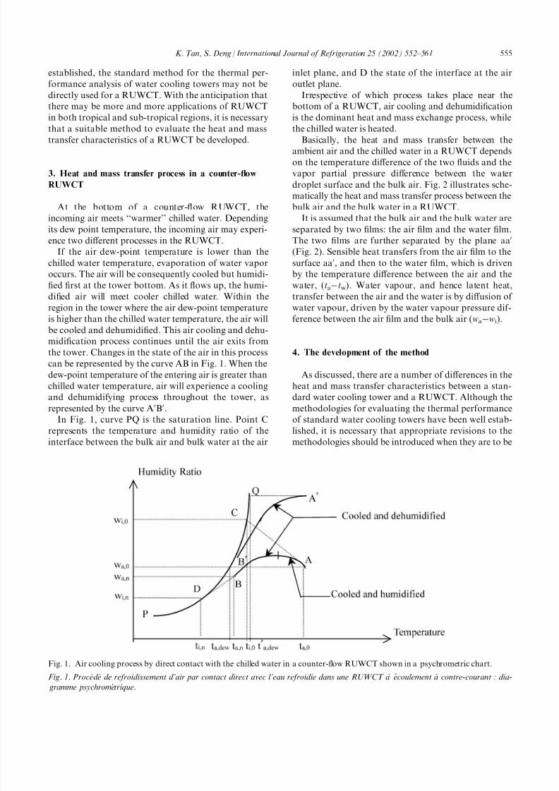
If the air dew-point temperature is lower than the
chilled water temperature, evaporation of water vapor
occurs. The air will be consequently cooled but humidi-fied first at the tower bottom. As it flows up, the humi-
dified air will meet cooler chilled water. Within the
region in the tower where the air dew-point temperature
is higher than the chilled water temperature, the air will
be cooled and dehumidified. This air cooling and dehu-
midification process continues until the air exits from
the tower. Changes in the state of the air in this process
can be represented by the curve AB in Fig. 1. When the
dew-point temperature of the entering air is greater than
chilled water temperature, air will experience a cooling
and dehumidifying process throughout the tower, as
represented by the curve A0B0.
In Fig. 1, curve PQ is the saturation line. Point C
represents the temperature and humidity ratio of the
interface between the bulk air and bulk water at the air
inlet plane, and D the state of the interface at the air
outlet plane.
Irrespective of which process takes place near the
bottom of a RUWCT, air cooling and dehumidification
is the dominant heat and mass exchange process, while
the chilled water is heated.
Basically, the heat and mass transfer between theambient air and the chilled water in a RUWCT depends
on the temperature difference of the two fluids and the
vapor partial pressure difference between the water
droplet surface and the bulk air. Fig. 2 illustrates sche-
matically the heat and mass transfer process between the
bulk air and the bulk water in a RUWCT.
It is assumed that the bulk air and the bulk water are
separated by two films: the air film and the water film.
The two films are further separated by the plane aa0
(Fig. 2). Sensible heat transfers from the air film to the
surface aa0, and then to the water film, which is driven
by the temperature difference between the air and thewater, (taÀtw). Water vapour, and hence latent heat,
transfer between the air and the water is by diffusion of
water vapour, driven by the water vapour pressure dif-
ference between the air film and the bulk air (waÀwi).
4. The development of the method
As discussed, there are a number of differences in the
heat and mass transfer characteristics between a stan-
dard water cooling tower and a RUWCT. Although the
methodologies for evaluating the thermal performance
of standard water cooling towers have been well estab-
lished, it is necessary that appropriate revisions to the
methodologies should be introduced when they are to be
Fig. 1. Air cooling process by direct contact with the chilled water in a counter-flow RUWCT shown in a psychrometric chart.
Fig. 1. Proce de de refroidissement d’air par contact direct avec l’eau refroidie dans une RUWCT a ` e coulement a ` contre-courant : dia-
gramme psychrome trique.
K. Tan, S. Deng / International Journal of Refrigeration 25 (2002) 552–561 555

8/8/2019 A Method for Evaluating the Heat and Mass Transfer
http://slidepdf.com/reader/full/a-method-for-evaluating-the-heat-and-mass-transfer 5/10
applied to a RUWCT. The method developed and
reported in this paper is based on the well-known
Merkel’s equation for standard water cooling towers.
For standard water cooling towers, the Merkel’s
equation is
dha
ha À hs
¼amdV
Gð1Þ
This was derived under the assumption that the water
side heat transfer resistance in a water cooling tower can
be neglected and the interface temperature, ti, is
approximately equal to tw. Therefore hs, the enthalpy of
saturated air at the interface, is evaluated at tw.
However, for RUWCT application, as discussed ear-
lier, the water side heat transfer resistance is significant
and cannot be neglected, so that ti6¼tw; and hs should be
evaluated at the interface temperature, ti. Therefore, the
first revision introduced to Eq. (1) is to replace hs by hi
dha
ha À hi
¼amdV
Gð2Þ
It is assumed that the interface temperature, ti, is an
algebraic average of the bulk air temperature and thebulk water temperature i.e. ti ¼ 1
2ðta þ twÞ:
This was initially based on the earlier discussion of
equal heat transfer resistance in both water- and air-
films in Norman’s experiments. A further detailed
analysis based on heat and mass transfer across the
interface, as shown in the Appendix, indicated such an
assumption is of acceptable accuracy[11].
The second revision introduced is that dha in Eq. (2) is
evaluated by
dha ¼LC w
GF dtw ð3Þ
where
F ¼ 1 ÀC wtwdL
Gdha
ð4Þ
F is a correction factor that accounts for the increase
of chilled water flow rate at the bottom of a counter-
flow RUWCT, and is derived as follows.
A schematic diagram of a counter-flow RUWCT that
has a plastic film packing of H height, and is divided into n
sections is shown in Fig. 3. Under steady, adiabatic flow
conditions, for a differential control volume dV (Fig. 3)
within the RUWCT, energy conservation requires
Fig. 2. An indicative schematic diagram of heat and mass transfer between bulk air and bulk water in a RUWCT.
Fig. 2. Sche ma du transfert de chaleur et de masse entre l’air en vrac et l’eau en vrac dans une RUWCT.
Fig. 3. A schematic diagram of a counter-flow RUWCT.
Fig. 3. Sche ma d’une RUWCT a ` e coulement a ` contre-courant.
556 K. Tan, S. Deng / International Journal of Refrigeration 25 (2002) 552–561

8/8/2019 A Method for Evaluating the Heat and Mass Transfer
http://slidepdf.com/reader/full/a-method-for-evaluating-the-heat-and-mass-transfer 6/10
Gdha ¼ C wd twLð Þ ð5aÞ
or
Gdha ¼ LC wdtw þ C wtwdL ð5bÞ
The second item on the right-hand side of Eq. (5b) isnormally omitted in the analysis of standard water
cooling towers. However, in a RUWCT, the chilled
water flow rate change, dL, resulting from condensation
of water vapor in moist air, cannot be neglected. Divid-
ing both sides of Eq. (5b) by Gdha, and making the
right-hand side of the new equation to be the correction
factor, F
LC wdtw
Gdha
¼ 1 ÀC wtwdL
Gdha
¼ F ð6Þ
Eq. (4) can be manipulated to
F ¼ 1 ÀC wtwðr0 þ hwÞdL
ðr0 þ hwÞGdha
ð7Þ
Given that the latent and the total heat transfer are
given by dQb=hvdL=(r0+hw)dL and dQT=Gdha, and
let =dQb/dQT, Eq. (4) becomes
F ¼ 1 ÀC wtwdQ
ðr0 þ hwÞdQT
¼ 1 À C wtw
r0 þ C wtw
ð8Þ
By definition, is the ratio of latent heat transfer to
the total heat transfer, which varies from plane to plane
inside the tower. It also varies with different tower con-
figurations and operational conditions of a RUWCT.However, for a particular RUWCT under a specific
operating condition, an averaged can be used in order
to simplify the analysis of a RUWCT.
As discussed in the last section, the latent heat trans-
fer is expected to be significantly lower in a RUWCT
than that in a standard water cooling tower. The intro-
duction of here makes it possible to quantify the
degree of reduction of latent heat transfer in a RUWCT.
Eq. (2) can be solved by using the revised Tchebycheff
quadrature method and using manufacturer’s data of a
specific tower [12].
Integrating both sides of Eq. (2) givesð dha
ha À hi
¼amV
Gð9Þ
The left-hand side of Eq. (9) is the dynamic char-
acteristics of tower (DCT), and the right-hand side of
Eq. (9) is the fill characteristics (FC), amV G
; a unique
Fig. 4. The schematic diagram for a desuperheater heat recovery system with a RUWCT.
Fig. 4. Sche ma d’un syste `me a ` de srchauffeur avec re cupe ration de chaleur avec une RUWCT.
K. Tan, S. Deng / International Journal of Refrigeration 25 (2002) 552–561 557

8/8/2019 A Method for Evaluating the Heat and Mass Transfer
http://slidepdf.com/reader/full/a-method-for-evaluating-the-heat-and-mass-transfer 7/10
characteristic of a specific tower. FC is the function of
L/G, expressed by
amV
G¼ C ð
L
GÞÀXN ð10Þ
where C and XN are constants [12, 13]. Using themanufacturers rating data, Eqs. (9) and (10) can be
solved using two different normal operating conditions
to determine the values of C and XN for a specific
RUWCT.
If the values of x are available either from tower man-
ufacturers or by experiments, Eqs. (2)–(10) can be used
together in an iterative process to calculate the outlet
water temperature tw,n, with the available inlet air states,
dry air flow rate, inlet chilled water temperature and flow
rate, etc. With an initial guess for tw,n, the calculation of
the FC and the DCT can proceed until convergence. The
convergence criteria applied in the calculation is
FC À DCT
FC
40:001 ð11Þ
If the criteria cannot be met in a calculation cycle, a
new guess of tw,n should be used and a new DCT is cal-
culated. Then the iterative procedure is repeated until
Eq. (11) can be satisfied. After the values of tw,n are
obtained, the extracted heat capacity, QA, and the out-
let air temperature, ta,n, can also be determined.
5. Field experimental work
Field experimental work has been carried out in a
chiller plant for a hotel building in a sub-tropical region
in China. The results of the field experimental work
helped obtain the values of , and demonstrated also
that the method developed is of an acceptable accuracy
for the performance evaluation of a RUWCT.
A water chiller of 116.3 kW (100,000 kcal/h) total
cooling capacity, which was retrofitted with a desuper-
heater, supplied both space cooling chilled water and
service hot water to the hotel building. The desuper-
heater, a shell-and-tube heat exchanger with appropriateinsulation, was installed outside the chiller. A standard
water cooling tower, which worked as a RUWCT, was
connected to chilled water loop in parallel with the fan
coils. This RUWCT was operated when necessary.
The schematic diagram of the experimental site is
shown in Fig. 4. Part of chilled water from the chiller
was pumped into the RUWCT for extracting heat from
the warm humid ambient air. With the extra heat source
from the operation of RUWCT, the desuperheater heat
recovery system can supply service hot water con-
tinuously to guestrooms in colder seasons, without
requiring any other backup heating provisions.
During the period of field measurements, outdoor
weather conditions varied. Measurements at five differ-
ent outdoor air dry-bulb temperatures were taken: 11.8,
15.2, 17.5, 21.7, 25.5C. Under each outdoor air dry-bulb
temperature, the supply chilled water flow rate to the
RUWCT was manually varied in order to obtain per-
formance data at different operating conditions. Fivedifferent chilled water flow rates were manually set:
1.48, 2.22, 2.96, 3.70 and 4.44 l/s.
To determine the actual values of at each chilled
water flow rate under a specific outdoor air temperature,
the measured air humidity ratio (from measured air dry-
and wet-bulb temperature) at the tower exit was com-
pared with the calculated air humidity ratio under an
initially assumed value. The value of could be mod-
ified and the comparison repeated until the measured
and calculated air humidity ratios were equal. The same
procedures were repeated for each chilled water flow
rate at a specific outdoor temperature to obtain the values at all operating conditions.
With the availability of values of , the outlet chilled
water temperature tw,n, and the total heat exchange QA
Table 1
Comparison of the measured and calculated results
Tableau 1
Comparaison des re sultats des mesures et calcule s
tdb twb tw,n tw,n0 Á QA QA0 Á
C C – C C C kW kW kW
L=1.48 l/s 11.8 10.7 0.39 8.7 8.93 0.23 10.5 10.16 0.3415.2 13.5 0.37 10.0 10.58 0.58 21.1 19.20 1.90
17.5 16.6 0.43 12.5 12.93 0.43 36.3 33.31 2.99
21.7 20.7 0.53 17.6 16.02 1.58 51.3 52.93 1.63
25.5 23.5 0.48 18.3 18.37 0.07 74.2 70.25 3.95
L=2.22 l/s 11.8 10.7 0.43 8.6 8.86 0.26 13.8 12.72 1.08
15.2 13.5 0.37 9.8 10.38 0.58 26.3 24.21 2.09
17.5 16.6 0.45 12.4 12.47 0.07 45.3 42.88 2.42
21.7 20.7 0.56 17.0 15.51 1.49 66.3 67.93 1.63
25.5 23.5 0.48 17.9 17.54 0.36 93.8 91.75 2.05
L=2.96 l/s 11.8 10.7 0.46 8.4 8.80 0.40 16.5 15.00 1.50
15.2 13.5 0.38 9.7 10.29 0.59 30.4 28.69 1.71
17.5 16.6 0.48 12.4 12.18 0.22 50.2 51.10 0.90
21.7 20.7 0.58 16.4 15.55 0.85 79.6 77.31 2.29
25.5 23.5 0.50 17.5 17.37 0.13 108.8 106.46 2.34
L=3.70 l/s 11.8 10.7 0.41 8.5 8.84 0.34 17.7 16.30 1.4
15.2 13.5 0.38 9.5 10.45 0.95 31.2 30.38 0.82
17.5 16.6 0.50 12.9 12.26 0.64 60.2 55.78 4.42
21.7 20.7 0.60 16.5 16.16 0.34 84.9 79.68 5.22
25.5 23.5 0.55 17.6 17.63 0.03 125.3 116.93 8.37
L=4.44 l/s 11.8 10.7 0.46 8.8 9.05 0.25 17.7 15.97 1.73
15.2 13.5 0.40 9.6 10.60 1.00 35.0 31.83 3.17
17.5 16.6 0.50 13.0 12.74 0.26 56.2 55.14 1.06
21.7 20.7 0.60 16.8 16.40 0.40 90.1 83.15 6.95
25.5 23.5 0.58 17.8 18.39 0.41 128.1 117.11 10.99
558 K. Tan, S. Deng / International Journal of Refrigeration 25 (2002) 552–561

8/8/2019 A Method for Evaluating the Heat and Mass Transfer
http://slidepdf.com/reader/full/a-method-for-evaluating-the-heat-and-mass-transfer 8/10
8/8/2019 A Method for Evaluating the Heat and Mass Transfer
http://slidepdf.com/reader/full/a-method-for-evaluating-the-heat-and-mass-transfer 9/10
7. Conclusions
This paper reports on a study of the heat and mass
transfer characteristic in a RUWCT for heat recovery
purpose. The differences in heat and mass transfer process
taking place in a RUWCT, a spray room and a standard
water cooling tower have been identified. A method bywhich the heat and mass transfer characteristics in a
counter-flow RUWCT can be evaluated has been devel-
oped. This was done by introducing to the Merkel’s
Equation for standard water cooling towers the revi-
sions that account for the identified differences in heat
and mass transfer between a water cooling tower and a
RUWCT. Field experimental results from a RUWCT
installed in a sub-tropical region in China indicated that
the method developed could be used to evaluate the
thermal performance of RUWCT with an acceptable
accuracy.
The introduction of is important in developing theevaluation method. The values obtained from the field
experimental work confirmed that the latent heat
exchange is reduced in a RUWCT.
The research work reported in this paper provides a
fundamental basis for studying heat and mass transfer
characteristics in a RUWCT. However, considering that
the current work was based on field experiments, further
experimental work in a controlled environmental labora-
tory is highly recommended, in order to have an
improved accuracy of analysis of the heat and mass
transfer characteristics in a RUWCT.
Acknowledgements
The fund from The Hong Kong Polytechnic Uni-
versity to support the project is gratefully acknowledged.
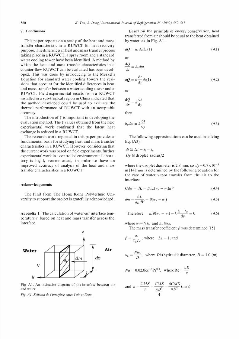
Appendix I The calculation of water-air interface tem-
perature ti based on heat and mass transfer across the
interface.
Based on the principle of energy conservation, heat
transferred from air should be equal to the heat obtained
by water, as in Fig. A1.
dQ ¼ hvdzdmð1Þ ðA1Þ
ordQ
dz¼ hvdm
dQ ¼ kdt
d ydzð1Þ ðA2Þ
or
dQ
dz¼ k
dt
d y
then
hvdm ¼ kdt
d yðA3Þ
The following approximations can be used in solving
Eq. (A3).
dt ffi Át ¼ ti À tw
Dy ffi droplet radius=2
where the droplet diameter is 2.8 mm, so dy=0.7Â10À3
m [14]. dm is determined by the following equation for
the rate of water vapor transfer from the air to the
interface
Gdw ¼ dL ¼ amðwa À wiÞdV ðA4Þ
dm ¼dL
amdV ¼ ðwa À wiÞ ðA5Þ
Therefore; hvðwa À wiÞ À kti À tw
d y¼ 0 ðA6Þ
where wi =f(ti ) and hv ffir0.
The mass transfer coefficient was determined [15]
¼
aC aLe ; where Le ¼ 1; and
a ¼Nul
D; where D is hydraulic diameter; D ¼ 1:0 ðmÞ
Nu ¼ 0:023Re0:8Pr0:3; where Re ¼uD
v
and u ¼CMS
s¼
CMS
D2
4
¼4CMS
D2m=sð Þ
Fig. A1. An indicative diagram of the interface between air
and water.
Fig. A1. Sche ma de l’interface entre l’air et l’eau.
560 K. Tan, S. Deng / International Journal of Refrigeration 25 (2002) 552–561

8/8/2019 A Method for Evaluating the Heat and Mass Transfer
http://slidepdf.com/reader/full/a-method-for-evaluating-the-heat-and-mass-transfer 10/10
Recommended

![UNSTEADY NATURAL CONVECTION BOUNDARY LAYER HEAT AND MASS ...scientificadvances.co.in/admin/img_data/690/images/[2] JPAMAA... · ... heat and mass transfer ... LAYER HEAT AND MASS](https://img.dokumen.tips/doc/110x75/5b3f0ca47f8b9a2f138ba06b/unsteady-natural-convection-boundary-layer-heat-and-mass-2-jpamaa-.jpg)