University of Arkansas, FayettevilleScholarWorks@UARK
Theses and Dissertations
8-2016
4D Printing Dielectric Elastomer Actuator BasedSoft RobotsJiyu CaiUniversity of Arkansas, Fayetteville
Follow this and additional works at: http://scholarworks.uark.edu/etd
Part of the Computer-Aided Engineering and Design Commons
This Thesis is brought to you for free and open access by ScholarWorks@UARK. It has been accepted for inclusion in Theses and Dissertations by anauthorized administrator of ScholarWorks@UARK. For more information, please contact [email protected], [email protected].
Recommended CitationCai, Jiyu, "4D Printing Dielectric Elastomer Actuator Based Soft Robots" (2016). Theses and Dissertations. 1680.http://scholarworks.uark.edu/etd/1680

4D Printing Dielectric Elastomer Actuator Based Soft Robots
A thesis submitted in partial fulfillment
of the requirements for the degree of
Master of Science in Mechanical Engineering
by
Jiyu Cai
Beijing University of Technology
Bachelor of Engineering in Mechanical Engineering and Automation, 2013
August 2016
University of Arkansas
This thesis is approved for recommendation to the Graduate Council
____________________________________
Dr. Wenchao Zhou
Thesis Director
____________________________________
Dr. Steve Tung
Committee Member
____________________________________
Dr. Adam Huang
Committee Member

ABSTRACT
4D printing is an emerging technology that prints 3D structural smart materials that can
respond to external stimuli and change shape over time. 4D printing represents a major
manufacturing paradigm shift from single-function static structures to dynamic structures with
highly integrated functionalities. Direct printing of dynamic structures can provide great benefits
(e.g., design freedom, low material cost) to a wide variety of applications, such as sensors and
actuators, and robotics. Soft robotics is a new direction of robotics in which hard and rigid
components are replaced by soft and flexible materials to mimic mechanisms that works in living
creatures, which are crucial for dealing with uncertain and dynamic tasks. However, little research
on direct printing of soft robotics has been reported.
Due to the short history of 4D printing, only a few smart materials have been successfully
4D printed, such as shape memory and thermo-responsive polymers, which have relatively small
actuation strains (up to ~8%). In order to produce the large motion, dielectric elastomer actuator
(DEA), a sheet of elastomer sandwiched between two compliant electrodes and known as artificial
muscle for its high elastic energy density and capability of producing large strains (~200%), is
chosen as the actuator for soft robotics. Little research on 3D printing silicone DEA soft robotics
has been done in the literature. Thus, this thesis is motivated by applying the advantages in 3D
printing fabrication methods to develop DEA soft robotics. The ultimate research goal is to
demonstrate fully printed DEA soft robots with large actuation.
In Chapter 1, the research background of soft robotics and DEAs are introduced, as well as
3D printing technologies. Chapter 2 reports the rules of selecting potentially good silicone
candidates and the printing process with printed material characterizations. Chapter 3 studies the
effects of pre-strain condition on silicone material properties and the performance of DEA

configurations, in order to obtain large actuation strain. In Chapter 4, two facial soft robots are
designed to achieve facial expressions as judged by a smiling lip and expanding pupils based on
DEA actuation. Conclusions and future developments are given in chapter 5.

ACKNOWLEDGEMENTS
I would like to express my deepest appreciation to my thesis advisor, Prof. WenChao Zhou,
for his support and guidance throughout my thesis research. It is a great opportunity to participate
in the 4D printing project in Dr. Zhou’s group. The experience gained during this project is very
helpful for my future development.
Besides my advisor, I would like to thank the rest of my thesis committee, Prof. Steve Tung
and Prof. Adam Huang for their encouragement, insightful comments, and important advising
about the independent thinking skill.
At last, I would like to deeply thank my family, especially my parents, for their support
and encouragement.

TABLE OF CONTENTS
1 INTRODUCTION ................................................................................................................... 1
1.1 Soft Robotics .................................................................................................................... 1
1.2 Dielectric Elastomer Actuators (DEAs) ........................................................................... 2
1.2.1 Comparison among smart materials and human muscle ........................................... 3
1.2.2 Fundamental principles of dielectric elastomer actuator .......................................... 4
1.2.3 Selective materials for dielectric elastomers ............................................................. 7
1.2.4 Previous research on dielectric elastomer actuators ................................................. 8
1.2.5 Current manufacturing methods ............................................................................... 9
1.3 3D Printing Techniques .................................................................................................. 10
1.4 4D Printing Review ........................................................................................................ 12
1.4.1 Literature Review of 4D Printing Dielectric Elastomer Actuator Cases: ............... 12
1.5 Motivation and Objective: .............................................................................................. 14
2 DIELECTRIC ELASTOMER ACTUATOR FABRICATION PROCESS .......................... 15
2.1 Introduction .................................................................................................................... 15
2.2 Principal Rules for Material Selection ........................................................................... 15
2.2.1 Dielectric elastomer: ............................................................................................... 16
2.2.2 Flexible electrodes and connecting wires: .............................................................. 18
2.2.3 Rigid frames ............................................................................................................ 18
2.2.4 Stretching base ........................................................................................................ 19
2.3 Fabrication Process ........................................................................................................ 20
2.3.1 Material preparation ................................................................................................ 21
2.3.2 Printing process ....................................................................................................... 23
2.3.3 Post-Process ............................................................................................................ 28
2.3.4 Assembling process for dielectric elastomer actuator ............................................ 29
2.4 Characterizations of Printed Materials ........................................................................... 30
2.4.1 Silicone film ............................................................................................................ 30
2.4.2 Carbon grease electrode .......................................................................................... 31
2.5 Conclusions: ................................................................................................................... 35
3 DIELECTRIC ELASTOMER ACTUATOR PERFORMANCE TESTS ............................. 36
3.1 Introduction .................................................................................................................... 36

3.2 Investigation of the Effect of Pre-strain Condition ........................................................ 36
3.2.1 Tensile tests ............................................................................................................. 37
3.2.2 Dielectric constant tests .......................................................................................... 44
3.2.3 Dielectric breakdown strength ................................................................................ 47
3.2.4 Estimation for Dielectric Elastomer Actuator Behavior ......................................... 51
3.2.5 Estimated actuation strain under 100% pre-strain condition .................................. 52
3.2.6 Result discussion ..................................................................................................... 53
3.3 Study of Different Dielectric Elastomer Actuator Configurations................................. 54
3.3.1 DEA actuation strain measurements by image processing ..................................... 54
3.3.2 Circular dielectric elastomer actuator behavior ...................................................... 56
3.3.3 Rectangular dielectric elastomer actuator behavior ................................................ 58
3.3.4 Finite element method (FEM) simulation ............................................................... 60
3.3.5 Result discussion ..................................................................................................... 66
3.4 Summary ........................................................................................................................ 67
4 DIELECTRIC ELASTOMER ACTUATOR SMILEY FACE ROBOT .............................. 69
4.1 Introduction .................................................................................................................... 69
4.2 Quantitative Theory of Smiley Lip ................................................................................ 69
4.3 Smiley Face Robot based on Circular Dielectric Elastomer Actuator ........................... 70
4.3.1 Robotic design based on the tested dielectric elastomer actuator behaviors .......... 70
4.3.2 Performance test of facial dielectric elastomer actuator soft robot ......................... 71
4.3.3 Result discussion ..................................................................................................... 72
4.4 Smiley Face Robot based on Rectangular Dielectric Elastomer Actuator ..................... 74
4.4.1 Smiley face robotic design via FEM simulation ..................................................... 76
4.4.2 Performance tests of rectangular dielectric elastomer actuator robot ..................... 79
4.4.3 Result discussion ..................................................................................................... 80
4.5 Summary: ....................................................................................................................... 80
5 CONCLUSION ..................................................................................................................... 82
6 FUTURE WORK .................................................................................................................. 83
Reference…………………………………………………………………………………………………………………………………85

LIST OF FIGURES
Figure 1. (a) Maximum strain, (b) maximum pressure, (c) response speed and (d) efficiency
comparison among human muscle, dielectric elastomer and other smart materials [13-
15] .................................................................................................................................... 4
Figure 2. (a) Non-linear elasticity or hyper-elasticity; (b) the varying Young’s modulus in
hyper-elasticity ................................................................................................................. 6
Figure 3. Material property comparison of two common dielectric elastomers ...................... 7
Figure 4. Fused deposition modelling method: 1 – nozzle ejecting molten material, 2 –
deposited material, 3 – controlled movable table ........................................................... 11
Figure 5. A schematic circular dielectric elastomer actuator ................................................ 15
Figure 6. Fab@Home printer with (a) Pressure-driven print head or (b) Motor-driven print
head ................................................................................................................................ 17
Figure 7. CAD model of assembled frames and clamps. ...................................................... 19
Figure 8. Stretching base showing assembled rectangular DEA with pre-strain condition .. 20
Figure 9. A printed silicone film with inconsistent appearance from insufficient degassing 21
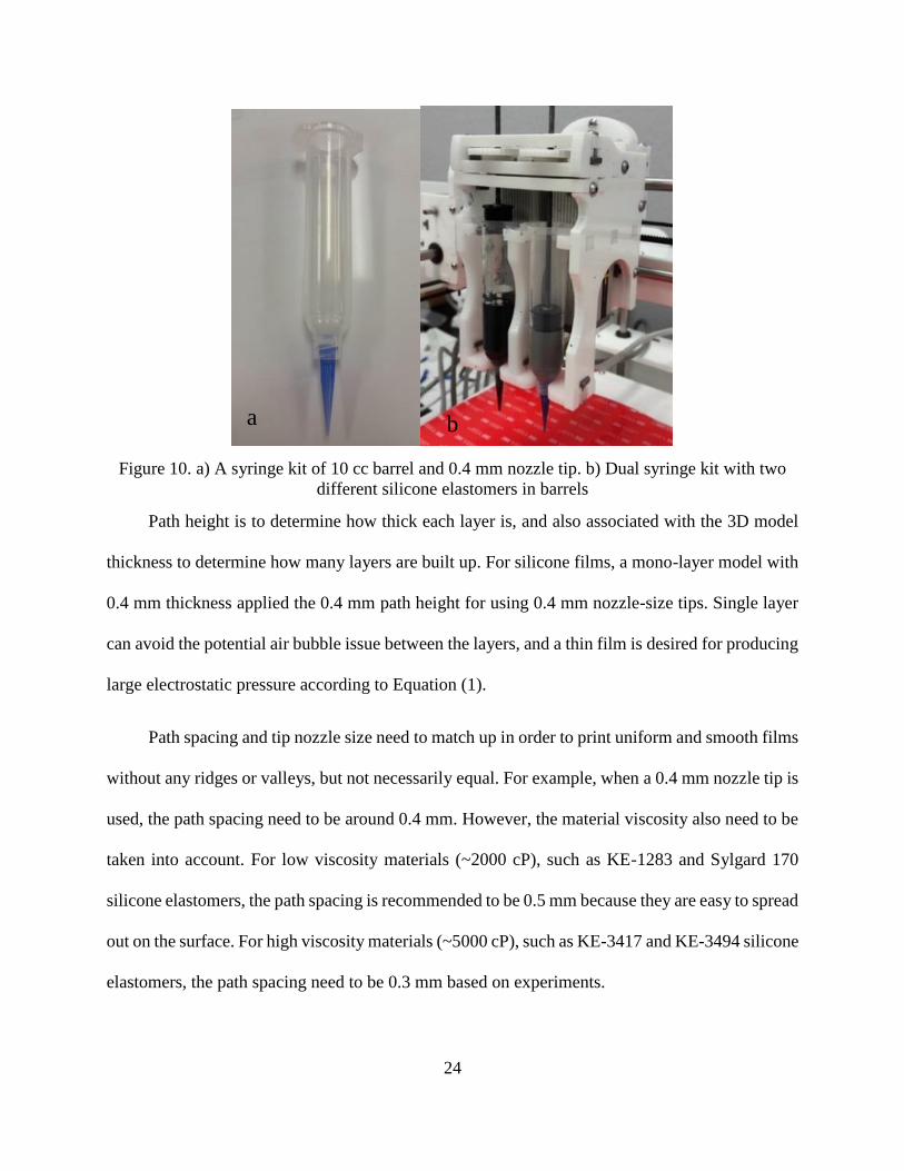
Figure 10. a) A syringe kit of 10 cc barrel and 0.4 mm nozzle tip. b) Dual syringe kit with
two different silicone elastomers in barrels.................................................................... 24
Figure 11. A good quality silicone elastomer film with extra areas ...................................... 25
Figure 12. Printing carbon grease under the optimal extruding pressure of 45 psi ............... 28
Figure 13. The configuration of a circular DEA ................................................................... 30
Figure 14. Measured film thickness of silicone membranes ................................................. 31
Figure 15. Conductivity versus stretch ratio testing setup ..................................................... 32
Figure 16. Conductivity result of printed carbon grease versus up to 100% elongation ....... 34
Figure 17. Cracks showing on carbon grease film under 100% elongation .......................... 35
Figure 18. Schematic dumbbell shape tensile specimen ....................................................... 38
Figure 19. (a) An example of molding 236 silicone elastomer (b) 236 silicone dumbbell
specimen being tensile tested ......................................................................................... 39
Figure 20. Elasticity curves of all silicone candidates. .......................................................... 40
Figure 21. Logarithmic Young’s modulus of all silicone candidates .................................... 40
Figure 22. The change of Young’s modulus of Sylgard 186 silicone showing how to
determine the applicable range of pre-strain .................................................................. 42

Figure 23. Dielectric constant measurement for printed silicone elastomers ........................ 44
Figure 24. Measured dielectric constant versus up to 100% elongation for each silicone
candidate......................................................................................................................... 46
Figure 25. HV testing setup for both dielectric breakdown measurements and DEA actuation
performance .................................................................................................................... 48
Figure 26. Validation of standard and measured dielectric breakdown strength .................. 49
Figure 27. . Measured dielectric breakdown strength versus different stretch ratios ............ 49
Figure 28. Comparison between empirical and modeling results of rectangular DEAs. ...... 52
Figure 29. Estimated actuation strain of rectangular silicone DEAs under 100% pre-strain
condition via this analytical method .............................................................................. 53
Figure 30. Experimental validation for MATLAB Image Processing method ..................... 55
Figure 31. Circular silicone DEA performances ................................................................... 57
Figure 32. Maximum actuation strain for circular silicone DEAs ........................................ 58
Figure 33. Rectangular silicone DEA performances ............................................................. 59
Figure 34. Measured actuation strains of rectangular silicone DEAs ................................... 60
Figure 35. FEM simulation for rectangular DEAs ................................................................ 64
Figure 36. Vertical actuation strain comparison between experiment and simulation results
at the membrane edge ..................................................................................................... 65
Figure 37. FEM simulation results for circular and rectangular DEAs ................................. 66
Figure 38. Quantitative theory of smiley lip .......................................................................... 70
Figure 39. Two examples of easily identified smiles showing smiley lip ratios ................... 70
Figure 40. A modified design using irregular electrode for small strain actuators ............... 71
Figure 41. Performance of circular DEA facial robot ........................................................... 72
Figure 42. FEM simulation of circular DEA to present the unexpectedly small lip
deformation .................................................................................................................... 73
Figure 43. FEM simulations for investigating the edge effect in rectangular DEA .............. 75
Figure 44. FEM simulation of the counter reaction from two neighboring electrodes ......... 76
Figure 45. Schematic drawing of rectangular smiley face robot ........................................... 77
Figure 46. Geometric parameter study of rectangular DEA robot ........................................ 78
Figure 47. FEM simulation of the optimal result from this smiley face robot ...................... 78

Figure 48. Initial status and maximum actuation of this smiley face robot ........................... 79

1
1 INTRODUCTION
1.1 Soft Robotics
Robots are often thought as machines with rigid bodies and rigid motions, resulting in rapid,
precise, and powerful movement in the certain environments. However, their functions are difficult
to perform in harsh and unpredictable environments or disastrous situations. In contrast, soft
robotics is a new direction of robotics in which hard and rigid components are replaced by soft and
compliant materials to mimic the actuation mechanisms of living creatures. Some soft biomimetic
robots associated with artificial muscle are earthworm robots [1, 2], hexapod inspired robots [3,
4], Gecko climbing robot [5] and micro flying insect robot [6]. Soft robots are convenient to apply
in uncertain and dynamic task-environments, such as manipulating unknown objects, performing
locomotion in rough terrains, and making contact with living cells and human bodies without
damages. In these cases, soft robots outperform rigid robots. For applications, there are huge
demands for soft robots due to their advantages aforementioned. For example, in 2014, $27 billion
profit was made in the Fresh-Cut Fruit and Vegetable Market in US, based on a Produce Marketing
Association (PMA) report. However, the American Farm Bureau Federation reported that $9
billion losses resulted from labor shortages. Hence, soft robots that easily handle soft and irregular-
shape fruit and vegetable are capable of solving huge loss in this food market, also to markets like
pharmacy.
Although there are huge interests and demands for soft robotics, researchers and engineers
have many fundamental difficulties in studying this field, including exploring unconventional
materials, developing fabrication methods and tools, establishing an agreement on the simulation
of soft continuum bodies, integrating actuation and control, and evaluating the communication in

2
soft robotics. These barriers, summarized by IEEE Robotics & Automation Society, are also the
research trend of soft robotics in the future.
As soft robotics developed over the past decades, manufacturing methods are evolving from
traditional machining, casting, and forging to more advanced approaches [7]. Although some soft
robots were fabricated using traditional manufacturing processes, the demand for more advanced
soft robotics has spurred the development of new manufacturing methods, such as shape deposition
methods (SDM) and smart composite microstructures (SCM). SDM, a solid freeform fabrication
(SFF) process, requires subtractive and additive manufacturing processes [8]. The subtractive
manufacturing processes cause high energy consumption and large wastes of materials. SCM
integrates the rigid structures with flexure joints and links, which is a fabrication process typically
using laser micromachining methods [6]. These advanced manufacturing processes provide
freedom in designing new types of 3D structured soft robots. Nonetheless, the manufacturing time
and cost are still expensive for these methods. In addition, the complex manufacturing processes
limit the robotic geometry and design freedom. Therefore, in order to further improve the freedom
of design, the ease of fabrication and customization, simpler and more direct manufacturing
technologies are desired.
1.2 Dielectric Elastomer Actuators (DEAs)
Soft robots are embedded with various sensors and actuators to achieve precise movement,
and one of the most important actuators in soft robotics is dielectric elastomer actuators (DEA).
Dielectric elastomer (DE) is a group of electroactive polymers (EAP) that can generate strains
under electric field, and DEA operates like a capacitor with a sheet of elastomer sandwiched
between two compliant electrodes, generating deformation under the electric field. DEA is

3
typically referred as “artificial muscle” for its ability to mimic mammalian muscles and its large
strain, lightweight and high energy density. Natural muscle uses many complex mechanisms
involving protein motion and regeneration from neural signals, while artificial muscle changes in
shape when an external stimuli are applied [9]. Many research about DEAs and applications have
started since 1990s, such as robotics [10], active vibration control of structures [11], and energy
harvesting [12].
In this section, a comprehensive introduction to DEAs is presented, including comparisons
among human muscle and DE and other smart materials, fundamental principles of DEAs, two
commonly used dielectric elastomer materials, and current manufacturing methods.
1.2.1 Comparison among smart materials and human muscle
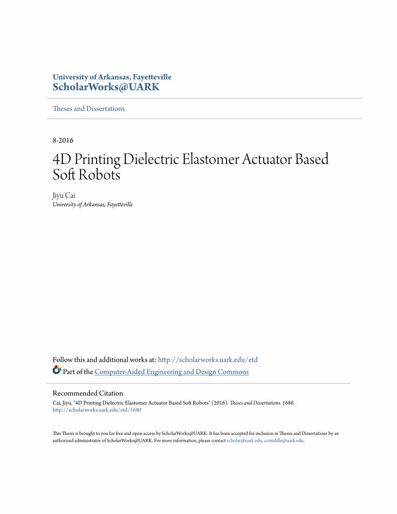
A survey about some key characteristics of DEA with human muscle and other smart
materials is completed in order to find the appropriate material mimicking human muscle. As
shown in Figure 1, human muscle and four smart materials, including dielectric elastomer,
electrostrictive polymer, piezoelectric polymer and shape memory polymer, are compared in terms
of their general properties. In Figure 1 (a), dielectric elastomer has about 380% maximum strain
that outperforms human muscle and other smart materials. In Figure 1 (b), all listed smart materials
can produce the maximum pressure larger than human muscle, and dielectric elastomer is capable
to produce about 10 times pressure than that of human muscle. In Figure 1 (c), human muscle can
respond to internal or external stimulus within 50 milliseconds, while dielectric elastomer is over
20 times faster than human muscle and hundreds of times than that of shape memory polymer. In
Figure 1 (d), working efficiency of DE is typically around 90%, which is two times than human
muscle, while shape memory polymer has a low efficiency of~10%. Hence, dielectric elastomer is
4
a promising material for making artificial muscles, due to the fact that it can outperform human
muscle and other smart materials in these key characteristics.
(a) (b)
(c) (d)
Figure 1. (a) Maximum strain, (b) maximum pressure, (c) response speed and (d) efficiency
comparison among human muscle, dielectric elastomer and other smart materials [13-15]
1.2.2 Fundamental principles of dielectric elastomer actuator
With its capability to outperform human muscles, dielectric elastomer has been used to
develop actuators for soft robot [9]. DEA operates like a capacitor, with a dielectric elastomer film
sandwiched by compliant electrodes. Upon applying voltage, the electrostatic force between the
electrodes squeezes the elastomer in the thickness direction and actuate the elastomer in the planar
direction. The equivalent electromechanical pressure is the Maxwell electrostatic pressure, which
is given by:

5
𝑝𝑒𝑞 = 𝜀0𝜀𝑟
𝑈2
𝑧2
(1)
where 𝜀0 is the vacuum permittivity, 𝜀𝑟 is the dielectric constant of the elastomer, U is the applied
voltage between electrodes and z is the thickness of elastomer membrane [16]. Compressive
Maxwell pressure causes mechanical deformation to DEAs, based on the general expression:
𝜀 =𝜎
𝐸
(2)
where 𝐸 is the Young’s modulus of material, 𝜎 is the Maxwell pressure, and 𝜀 is the strain
responding to the stress. Dielectric elastomer is squeezed in the direction of Maxwell pressure, and
expands in other two directions, from the general expression of Poisson ratio:
𝛾 =𝑑𝜀𝑡𝑟𝑎𝑛𝑠
𝑑𝜀𝑎𝑥𝑖𝑎𝑙
(3)
where 𝛾 is the Poisson ratio, 𝑑𝜀𝑎𝑥𝑖𝑎𝑙 is the derivative axial strain, 𝑑𝜀𝑡𝑟𝑎𝑛𝑠 is the derivative
transverse strain. For incompressible dielectric elastomers, Poisson ratio is assumed to be 0.5.
From understanding the fundamental principles of DEA, the properties of dielectric
elastomers play a significant role on DEA actuation. Some desirable properties for producing large
actuation strain include high dielectric constant, high breakdown strength, and low Young’s
modulus. However, most of dielectric elastomers have a non-linear hyper- elasticity, which means
Young’s modulus changes with strain. An example of hyper- elasticity curve of dielectric
elastomers shows the varying Young’s modulus in the below Figure 2. It is obvious that Young’s
modulus in region 2 is much smaller than those of region 1 and 3, so large actuation is easily
achieved in region 2 that has a lower Young’s modulus. In order to obtain large DEA actuation,
an important approach is to apply pre-strain to stretch silicone to achieve the low Young’s modulus

6
in region 2 prior to DEA actuation. Pre-strain condition plays an essential role in increasing DEA
actuation.
(a) (b)
Figure 2. (a) Non-linear elasticity or hyper-elasticity; (b) the varying Young’s modulus in hyper-
elasticity
Besides reducing Young’s modulus of dielectric elastomer, pre-strain condition was found
the positive relationship to increase the dielectric breakdown strength. In the literature, there were
a lot of papers reporting the effects of pre-strain on DEA actuation, such as reducing Young’s
modulus and increasing dielectric breakdown strength [17-19]. For example, silicone elastomer
generally has a maximum uniaxial elongation larger than 75%, and the pre-strain have been shown
as an effective approach to increase DEA actuation strain by experiments and simulations [17]. A
study of different pre-strain modes, such as uniaxial, equi-biaxial, and planar stretching modes,
were presented by Yang [18]. He reported that DEA actuation was dependent on different pre-
strain modes and the equi-biaxial mode would stiffen dielectric elastomer to weaken its actuation.
From his experiments, Dow Corning HSIII RTV silicone DEA was shown to have a peak actuation
of 160 μm over 20 mm active length at a 15% pre-strain through experiments. In addition, a 10
times actuation strain from 7.7% to 80% of a uniaxial actuator made of Sylgard 186 silicone
7
elastomer was reported when a 175% pre-strain was applied [19]. This paper also reported that
excessive pre-strain could stiffen the elastomer and increase the requirement for actuation voltage.
1.2.3 Selective materials for dielectric elastomers
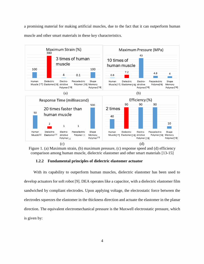
Two of the most common dielectric elastomer materials are acrylic and silicone elastomers.
They have different advantages and disadvantages. Specifically, acrylic elastomers can produce
the relatively large strain up to 380% and have the high dielectric constant, while silicones
generally have the high electromechanical response speed, long durability, large range of operating
temperature and high energy efficiency, shown in the Figure 3 [20]. Most of silicone products are
in liquid form or gel form, and can easily be turned into solid form via certain curing processes.
Due to the ease of processing and customization, silicone has wider applications than acrylic
elastomer, which is typically in solid form.
Figure 3. Material property comparison of two common dielectric elastomers
8
1.2.4 Previous research on dielectric elastomer actuators
In addition, many investigations have done on various aspects of DEAs, such as the geometry
of the compliant electrodes [11], the breakdown strength [21-23], and the enhancement of silicone
dielectric and mechanical properties [9, 24-29]. One study demonstrates a heart-shape DEA that
could expand and remain in heart shape with fast response at a high frequency of 20 kHz [11],
which indicates that DEA actuation is isotropic.
DEAs typically break down in three different ways, the electrical, the partial discharge, and
the thermally initiated breakdown [21]. The partial discharge and thermally initiated breakdowns
during the short testing period can be mitigated. The electrical breakdown or dielectric breakdown
that is dielectric elastomer’s electrical property limits the maximum voltage that can be applied on
DEAs, so limits the DEAs actuation. Dielectric breakdown strength is also relevant to the material
physical properties, such as mechanical stiffness, thickness, and pre-strain. The empirical results
showed that the dielectric breakdown strength of silicone elastomer films as actuators can be
enhanced by decreasing thickness or increasing pre-strain [22]. In addition, un-cured or not fully
cured silicone gel has a comparatively lower dielectric breakdown strength than fully cured
silicone [23].
It is desirable to have a large dielectric constant for large electrostatic pressure, which can
produce large mechanical strain. Many different approaches have been developed for increasing
the dielectric constant of dielectric elastomers. Three approaches were explored, including random
composites, field-structured composites, and new synthetic polymers [9]. To illustrate, random
composite approach is to fill and disperse either solid (powders) or liquid materials into dielectric
elastomer, such as ferro/piezoelectric ceramics, metal conductive particles, and organic polymers.
Field-structured composite approach is by mixing dielectric elastomers with some
9
ferro/piezoelectric ceramics and curing them in an external electric field to form the bipolar
molecular structure so as to increase dielectric constant. The polymer synthesis approach creates
a new molecular structure of dielectric elastomer materials by copolymerization.
For silicone dielectric elastomer, random composite is a typical approach for enhancing
dielectric constant by studying the impact of the types and content of fillers on the DEAs
performance. For example, some high dielectric constant materials were added in pure silicone to
enhance its dielectric constant, such as ferro/piezoelectric ceramics (titanium dioxide and BaTiO3
powders) [24, 25] and multi-walled carbon nanotubes [26]. However, adding high dielectric
constant materials may increase the elastic modulus and the decrease of the breakdown strength,
which are not desirable for DEAs [25]. Softening the materials is another type of random
composite method through adding plasticizers to enable large deformation at relatively low electric
field [27]. In addition, there are examples demonstrating the synthesis approaches to improve
silicone dielectric constant, such as copolymerizing copper-catalysed azide-alkyne 1,3-dipolar
cycloaddition (CuAAC) [28] and polar cyanopropyl group polymers [29].
1.2.5 Current manufacturing methods
Current manufacturing methods for fabricating silicone DEA are spin-coating and spray
coating. In the paper [30], spin-coating method for uncured silicone dielectric elastomer membrane
was studied by using a spin coater, and sample characterizations by this method were also
investigated. They found that this spin-coating method was efficient to produce massively thin
silicone membranes of less than 10 μm thicknesses. However, sophisticated geometry and 3D
structural configuration of DEA is difficult to be fabricated though this method.
10
Another paper presented that spray-coating method for fabricating uncured silicone
elastomer is advantageous on scalability, flexibility for different DEA configuration, and
multilayered assembly for a high degree DEA actuation [31]. For example, a multi-layered silicone
DEA of 67μm single layer thickness was demonstrated through this method. However, the
electrode fabrication process requires an extra mask to partially airbrush graphite powder on the
silicone film, which causes the complexity of the entire DEA fabrication. Also, different
geometries of silicone membranes is complex to achieve through this method.
In summary, two commonly manufacturing methods for DEAs are discussed. The spin
coating method is good at achieving thin film silicone elastomer with good uniformity, while the
spray coating method is advantageous on fabricating 3D structural stacked DEAs. They both are
efficient to produce massive DEAs in short time. However, free design and customization for
sophisticated DEA-base soft robotics are extremely difficult to obtain from these methods. Hence,
this research is motivated to develop a digital fabrication method for DEA based soft robots via
advanced manufacturing methods, like 3D printing technologies.
1.3 3D Printing Techniques
3D printing, also known as additive manufacturing, is a digital manufacturing method that
builds a three-dimensional object from a digital model layer by layer. The first prototype system
of 3D printing technology, stereo-lithography (SL), was developed by Chuck Hull in 1984. Until
now, many 3D printing techniques, such as fused deposition modeling (FDM), inkjet printing,
selective laser melting (SLM) and selective laser sintering (SLS), have been developed.
Two types of 3D printing techniques are used in this thesis, such as fuse deposition modeling
(FDM) and syringe-based extrusion. First of all, FDM is a typical additive manufacturing

11
technology that deposits the layered plastic filament or metal wire from a coil, shown in the Figure
4. Plastic filament or metal wire heats in the extrusion print head, and then molten material is
extruded and fused with printed material. FDM software reads a STL file format. The material
deposition rate is controlled by the extrusion rate of plastic filament or metal wire, and the fine
resolution is achieved by both precise motion in motor stage and nozzle tip size. Generally, 0.4
and 0.2 mm nozzle-size tips are used for both 2.85 and 1.75 mm diameter filament to achieve
different resolutions. In this thesis, Acrylonitrile butadiene styrene (ABS) thermoplastic filament
of 2.85 mm is applied on Ultimaker 2 through 0.4 mm nozzle-size tip.
Figure 4. Fused deposition modelling method: 1 – nozzle ejecting molten material, 2 – deposited
material, 3 – controlled movable table
(Wikipedia: https://en.wikipedia.org/wiki/Fused_deposition_modeling)
Another type of 3D printer, Fab@Home model 3, is employed for fabricating main
components in DEAs. Fab@Home printer is a material extrusion based multi-material printer. On
our Fab@Home printer, two liquid materials can be deposited from a dual-syringe print head,
simultaneously. Two different types of print heads, motor-driven and pressure-driven print heads,
are used in this thesis, and their differences are discussed in the DEA fabrication process in Chapter
2.
12
3D printing techniques have made significant strides during the past decades, enabling the
direct fabrication of 3D structures. These advanced techniques reduce the complexity in fabrication
from the conventional subtractive manufacturing methods, improve the efficiency in time and
materials, and offer more customization in design freedom. Hence, 3D printing is a promising
technique for the direct fabrication of soft robotics.
1.4 4D Printing Review
4D printing, as an extension of 3D printing, is an emerging technology that prints 3D
structures with smart materials, which can respond to external stimuli and change shape or
properties over time. 4D printing was first presented from Massachusetts Institute of Technology
(MIT) in 2009, by demonstrating a 4D printed temperature-responsive polymer, which was
programmed to show “MIT” and “SAL” [32]. 4D printing represents a major manufacturing
paradigm shift from single-function static structures to dynamic structures with highly integrated
functionalities. Direct printing of dynamic structures can provide great benefits (e.g., design
freedom) for a wide variety of applications, such as sensors, actuators, and robotics. Due to its
short history, only a few smart materials have been successfully 4D printed for various applications,
including shape memory polymers [33, 34], and ionic electroactive polymers [35]. Massive
research is encouraged to explore more applications for the 4D printing technology.
1.4.1 Literature Review of 4D Printing Dielectric Elastomer Actuator Cases:
Dielectric elastomers are known as artificial muscle materials for various applications due
to large actuation, light weight and high energy density. The significant DEA development
progress has been made, including a few papers reporting directly 3D printing DEAs, similar to

13
this thesis. However, the research gaps found from these papers are discussed to ensure that this
research produces new knowledge and contribution.
In 2009, Rossiter J. et al. presented a new approach to the fabrication of soft dielectric
elastomer actuators via 3D printing technologies [36]. They emphasized that 3D printing
technologies have the capability of forming complex three-dimensional structures, like actuators
and sensors. The contribution of this paper was developing a 3D printing process for acrylic
elastomer membrane and frame structure through stereo-lithography (SL) process and designing a
novel 3D structural DEAs that involves pre-strain mechanism. However, the low performance of
their printed acrylic DEA was 0.12 mm maximum displacement over a 20 mm active length, which
is 0.6% actuation strain, because acrylic-based photopolymer materials (resin) only had 50%
maximum elongation.
Another study on inkjet 3D printing DEAs was reported in 2008 at the University of
California at Berkeley [37]. They studied the inkjet 3D printing process, dielectric breakdown
strength study and the design of printable pre-strain structures for silicone DEAs. However, the
DEA behavior test was actually conducted on VHB 4910 acrylic DEAs that was not 3D printed.
VHB 4910 acrylic is in solid phase that is not printable on the inkjet 3D printer, and they manually
made those acrylic membranes stretched on the rigid frames. In addition, they did not demonstrate
any DEA based soft robotics through 3D printing techniques.
This literature review reveals that very little research on the 3D printed DEAs has been very
preliminary, and 0.6% actuation strain on the 3D printed DEA was too small to match with
promising performance of these artificial muscle materials with over 100% maximum elongation.

14
In addition, the design freedom in 3D structural DEA soft robotic endowed by 3D printing
techniques was not well exploited.
1.5 Motivation and Objective:
From literature survey, it is clear that little research has been done on 3D printing silicone
DEA soft robot with large actuation strain. Hence, the research objective of this thesis is to develop
fully printed DEA soft robotics with large actuation strain. In this thesis, I will first develop a 3D
printing process for silicone DEA, and then investigate the DEA behavior for selecting the best
silicone candidates, and finally fabricate a DEA soft robot that meets the desired functions, which
will be discussed respectively in Chapter 2, 3, and 4 respectively.

15
2 DIELECTRIC ELASTOMER ACTUATOR FABRICATION PROCESS
2.1 Introduction
In this chapter, a 3D printing process for fabricating silicone elastomer membrane and carbon
grease electrode is developed. It is organized to be three sections. In the first section, the principal
rules for selecting appropriate materials based on material properties are discussed. In the second
section, the entire fabrication process for silicone DEA is discussed, including material preparation
process, printing process, post-curing, and assembly. In the last section, the characteristics of these
printed materials are tested.
2.2 Principal Rules for Material Selection
Material properties play an important role in obtaining large DEA actuation. Understanding
fundamental principles of DEA actuation is very helpful to select right and appropriate materials
from a large amount of candidates. In the DEA configuration, a circular DEA is composed of
dielectric elastomer film, electrode and circular rigid frame. In this section, the rules of selecting
silicone dielectric elastomer, electrode and frame are discussed, respectively.
Figure 5. A schematic circular dielectric elastomer actuator

16
2.2.1 Dielectric elastomer:
The primary challenge for achieving the large deformation is to select the appropriate
dielectric elastomer materials. Among all types of dielectric elastomers, silicone elastomer is
chosen because of its ease of processing, higher working efficiency, and faster response time than
acrylic elastomer. However, there are hundreds of commercial silicone elastomers on the market,
because many different types of fillers are added in pure silicone to enhance its different properties
for various applications. For our application, some key material properties of silicone dielectric
elastomer are desired based on the DEA actuation principles, such as high dielectric constant and
dielectric breakdown strength for generating large pressure, and low Young’s modulus for
obtaining large strain.
Besides these factors above, viscosity is another important factor. Higher viscosity materials
require more pressure to be extruded from a small nozzle. Fab@Home syringe-base print heads
can produce pressure up to 80 psi. For the motor-driven and pressure-driven print heads, the upper
limit of printable viscosities are 10,000 cP and 100,000 cP motor-driven, respectively, shown in
the below Figure 6. In addition, low viscosity silicone is preferred for ease of fabrication. For
example, it is much easier to degas silicone with lower viscosity, which is a critical step for
preparing the materials for printing. High viscosity make it more difficult for the air bubbles to get
out.

17
(a) (b)
Figure 6. Fab@Home printer with (a) Pressure-driven print head or (b) Motor-driven print head
Four silicone elastomers of within 10,000 cP viscosity from different manufacturers are
selected to print via the motor-driven print head, including ShinEtsu KE-1283, KE-3417 and KE-
3494 and Dow Corning Sylgard170, shown in the Table 1. Six silicone elastomers with a wider
range of up to 100,000 cP viscosity were selected to print via the pressure-driven print head,
including Momentive LIM6010, Nusil R2188 and R3-1075, and Dow Corning 236, SE9186 and
Sylgard186 in the Table 2.
Table 1. Material properties for Group 1 silicone elastomer from motor-driven print head
KE-1283 KE-3417 KE-3494 Sylgard170
Viscosity (cP) 2000 5000 5000 2135
Tensile Strength (MPa) 0.2 1.7 2.5 -
Elongation at break (%) 300 260 250 -
Dielectric Constant 4 3.2 3.5 2.54
Dielectric breakdown
strength (kV/mm) 25 19.68 25 18

18
Table 2. Material properties for Group 2 silicone elastomer from pressure-driven print head
Sylgard186 SE9186 LIM6010 R-2188 R3-1075 236
Viscosity (cP) 66,700 64,000 30,000 11,300 3,300 675
Tensile strength (MPa) 2.1 2.5 2.76 3.3 4.8 2.24
Elongation at break (%) 255 550 510 350 350 500
Dielectric Constant 2.7 2.7 - 2.9 - -
Dielectric breakdown
strength (kV/mm) >14 23 - 19.5 49.2 >14
2.2.2 Flexible electrodes and connecting wires:
For electrodes, it is critical to select a flexible and stretchable conductive material with
extremely low Young’s modulus that can provide uniform charge distribution over the surface
under large deformation. It was reported in the literature that carbon conductive grease can meet
these requirements for the electrode in DEA. MG carbon conductive grease is selected in this
research, and its volume resistivity is 1.17 ohm*cm from the supplier. In addition, copper wire is
used to connect compliant electrodes to a high voltage supply.
2.2.3 Rigid frames
DEAs need frames for supporting itself for both fabricating and actuating. Frames should be
strong enough for holding the pre-stretched soft silicone elastomers. The rigid frames made of
ABS plastic were applied with two different configurations, circular and rectangular. The effects
of different configurations on DEA actuation is discussed in the next chapter.
2.2.3.1 Circular rigid frames
A circular rigid frame is designed to tightly hold the pre-stretched silicone membrane as
shown in Figure 7, which can also protect the printed electrodes and wire traces on both sides of
dielectric elastomer film from touching the platform of the Fab@Home printer during printing.
19
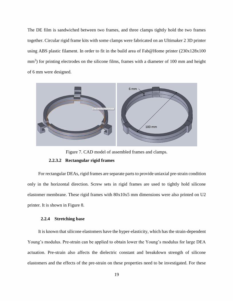
The DE film is sandwiched between two frames, and three clamps tightly hold the two frames
together. Circular rigid frame kits with some clamps were fabricated on an Ultimaker 2 3D printer
using ABS plastic filament. In order to fit in the build area of Fab@Home printer (230x128x100
mm3) for printing electrodes on the silicone films, frames with a diameter of 100 mm and height
of 6 mm were designed.
Figure 7. CAD model of assembled frames and clamps.
2.2.3.2 Rectangular rigid frames
For rectangular DEAs, rigid frames are separate parts to provide uniaxial pre-strain condition
only in the horizontal direction. Screw sets in rigid frames are used to tightly hold silicone
elastomer membrane. These rigid frames with 80x10x5 mm dimensions were also printed on U2
printer. It is shown in Figure 8.
2.2.4 Stretching base
It is known that silicone elastomers have the hyper-elasticity, which has the strain-dependent
Young’s modulus. Pre-strain can be applied to obtain lower the Young’s modulus for large DEA
actuation. Pre-strain also affects the dielectric constant and breakdown strength of silicone
elastomers and the effects of the pre-strain on these properties need to be investigated. For these

20
investigations, a stretching base was designed to apply different pre-strain as shown in Figure 8.
This stretching base clamps rigid frames of rectangular DEAs, and stretches DEAs by tuning the
butterfly nuts on thread rods. A ruler is taped to the base to determine the stretch ratio. This
structure kit including screw nuts are all designed in Solidworks and then printed on a FDM printer.
Figure 8. Stretching base showing assembled rectangular DEA with pre-strain condition
2.3 Fabrication Process
In the DEA fabrication process, 3D printing techniques are applied due to their reliability of
good quality of the printed materials, such as accuracy and consistency. Our objective is to
fabricate all DEA components, except copper wires, via 3D printing techniques to achieve a fully
printed DEA. It is essential to study the 3D printing fabrication process for obtaining good quality
DEAs. Silicone films and carbon grease films are printed on syringe based Fab@Home multi-
material 3D printer, and the stretching base and rigid frames are printed on FDM printers.
Stretching base
Ruler
Thread rod & Butter fly nut
Clamps
Rectangular DEAs

21
It is fairly straightforward to print on FDM printers, while it is new to print silicone and
carbon grease through a material extrusion based multi-material printer, which is the focus in this
chapter. The main procedures in this fabrication process are developed, including material
preparation, printing process with the printing parameter study, post-curing, and assembly as
described in each sub-sections below. Two groups of silicone candidates, printed via different print
heads, are discussed in each step, respectively.
2.3.1 Material preparation
Before the printing process starts, materials need to do some preparations for printing. One
critical issue reported in the literature is that air bubbles are easily trapped in viscous materials,
inducing the inconsistency in material appearances and defects in the printed parts [25]. An
example of a printed silicone film without sufficient degassing shows the bad quality of the
inconsistent print in Figure 9 below. To eliminate the air bubble issue, a vacuum chamber kit that
can extract about 28.5 inches mercury pressure is used to degas silicone elastomers.
Figure 9. A printed silicone film with inconsistent appearance from insufficient degassing

22
The results of the degassing process are influenced by two parameters: the extracting
pressure and duration. The maximum extracting pressure is determined by the power of the
vacuum pump, while only duration is the controllable parameter. Experiments showed that 30
minutes of degassing were sufficient and effective for low and medium viscosity silicones of less
than 10,000 cP. Through observation, air bubbles in the low viscosity silicones are much easier to
remove, such as KE-1283 and Sylgard 170 silicone elastomers. Another issue involved in
degassing process is that fast-cure silicones may cure during the degassing process due to the rapid
loss of moisture in vacuum condition. Of the four selected silicone products, KE-3417 and KE-
3494 silicones cure fast, typically in one hour, while KE-1283 and Sylgard 170 elastomers cure in
more than 5 hours. The alternative operation for fast-cure silicone is to degas in three iterations of
10 minutes, instead of one iteration of 30 minutes, and at each break the cured silicone must be
removed so as not to block air bubbles coming out. In order to avoid this issue, the slow-cure
silicone elastomers are preferred for easier degassing process, such as KE-1283 and Sylgard 170.
For high viscosity silicone, the degassing duration in the vacuum chamber need to be longer.
For example, Dow Corning Sylgard 186 silicone with 66,000 cP viscosity took about 4 hours to
eliminate bubbles inside of silicone, but still some bubbles stayed at top of syringe barrels.
In addition, a mixing process is sometimes required for two parts material, like Sylgard 186
and LIM 6010 silicone, prior to degassing process. Based on their material datasheet, part A and
part B materials are poured in a beaker at the given mixing ratio by weight using a mass scale with
1 μg resolution. Then, two parts are manually stirred by using a teaspoon for 1 minute as suggested
in their material datasheets.

23
2.3.2 Printing process
Fab@Home multi-material printer is used for printing silicone films and carbon grease films.
On a Fab@Home printer, two print heads are used for different purposes. For example, the motor-
driven print head is good for the ease of fabrication, while the pressure-driven print head is capable
of producing high pressure for extruding high viscosity materials. The adjustable process
parameters for motor-driven print head are deposition rate, path speed, path spacing, path height,
and syringe tip nozzle size, as explained in the Table 3. While the deposition rate parameter
changes to air pressure when the pressure-driven print head is being used, also explained in the
Table 3. The good quality of printed dielectric elastomer films, such as uniformity, smoothness
are dependent on these process parameters. The fabrication processes though two print heads are
discussed in the following sections, respectively.
Table 3. Description of the printing parameters of Fab@Home printer
Deposition rate
(OR air pressure)
The extruding rate in motor-driven print head
(OR extruding pressure in pressure valve print head)
Path speed The traveling speed of the print head while printing
Path spacing The spacing between two parallel paths
Path height The single layer thickness
Syringe tip size Tip nozzle size, also the diameter of extruded material line
2.3.2.1 Fabrication process through motor-driven print head
The printing process for silicone elastomer was conducted on the Fab@Home printer using
a dual-syringe kit with 10 cc syringe barrels and 0.4 mm nozzle size tips, shown in Figure 10. The
impact of each parameter on the quality of the print is explained below.
24
Figure 10. a) A syringe kit of 10 cc barrel and 0.4 mm nozzle tip. b) Dual syringe kit with two
different silicone elastomers in barrels
Path height is to determine how thick each layer is, and also associated with the 3D model
thickness to determine how many layers are built up. For silicone films, a mono-layer model with
0.4 mm thickness applied the 0.4 mm path height for using 0.4 mm nozzle-size tips. Single layer
can avoid the potential air bubble issue between the layers, and a thin film is desired for producing
large electrostatic pressure according to Equation (1).
Path spacing and tip nozzle size need to match up in order to print uniform and smooth films
without any ridges or valleys, but not necessarily equal. For example, when a 0.4 mm nozzle tip is
used, the path spacing need to be around 0.4 mm. However, the material viscosity also need to be
taken into account. For low viscosity materials (~2000 cP), such as KE-1283 and Sylgard 170
silicone elastomers, the path spacing is recommended to be 0.5 mm because they are easy to spread
out on the surface. For high viscosity materials (~5000 cP), such as KE-3417 and KE-3494 silicone
elastomers, the path spacing need to be 0.3 mm based on experiments.
a b
25
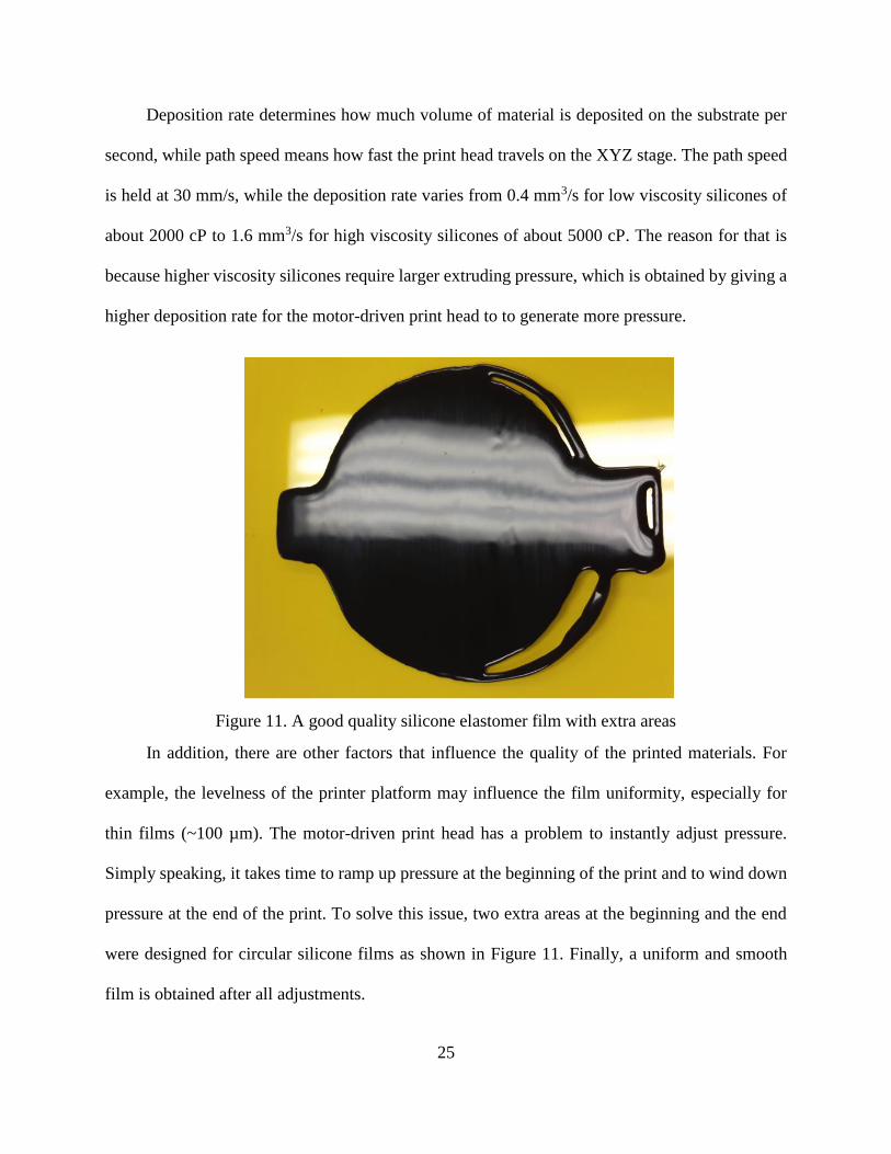
Deposition rate determines how much volume of material is deposited on the substrate per
second, while path speed means how fast the print head travels on the XYZ stage. The path speed
is held at 30 mm/s, while the deposition rate varies from 0.4 mm3/s for low viscosity silicones of
about 2000 cP to 1.6 mm3/s for high viscosity silicones of about 5000 cP. The reason for that is
because higher viscosity silicones require larger extruding pressure, which is obtained by giving a
higher deposition rate for the motor-driven print head to to generate more pressure.
Figure 11. A good quality silicone elastomer film with extra areas
In addition, there are other factors that influence the quality of the printed materials. For
example, the levelness of the printer platform may influence the film uniformity, especially for
thin films (~100 µm). The motor-driven print head has a problem to instantly adjust pressure.
Simply speaking, it takes time to ramp up pressure at the beginning of the print and to wind down
pressure at the end of the print. To solve this issue, two extra areas at the beginning and the end
were designed for circular silicone films as shown in Figure 11. Finally, a uniform and smooth
film is obtained after all adjustments.
26
2.3.2.2 Fabrication process through pressure-driven base print head
Pressure-driven base print head is typically applied for printing high viscosity materials. A
different configuration file is loaded in the control software of Fab@Home printer. One key
printing parameter is changed from deposition rate to air pressure, which directly controls the
extruding pressure. Other parameters work in the same ways with that of dual-motor print head.
Pressure-driven print head is advantageous on instantly adjusting pressure during printing
by turning the internal pressure valve on or off. However, an issue associated with this print head
is that switch valves have to be replaced after every print, because silicone finally solidifies inside
of switch valve and blocks flows. The cured silicone is very difficult to be removed or dissolved
by typical cleaning chemicals, such as isopropyl alcohol and acetone, which may damage the
plastic switch valve. Some special cleaning solvents provided from silicone manufacturers can be
used for the cured silicone elastomers.
Printing high viscosity material is discussed here. The ultimate goal for printing silicone is
to obtain good quality of thin silicone films without any inconsistency. 3D model of silicone film
is designed with 0.4 mm thickness for using 0.4 mm nozzle-size tips. Path spacing and path height
that are related to nozzle size both are determined to be 0.4 mm. Path speed that controls the
traveling speed of the print head is set as default 30 mm/s. Hence, air pressure is the only variable
to study for printing silicone elastomer and carbon grease.
In the parameter study, three different air pressures are studied for each material in order to
obtain a thin film with good quality. For example, 5 psi pressure was first applied to print SE9186
silicone through 0.4 mm nozzle-size tip, and a 180 μm thick film with inconsistent quality was
obtained. Then, 20 psi air pressure was used to print a silicone film with 380 μm thickness and

27
consistent film quality, but it is too thick. Finally, a film thickness of 230 μm was achieved by
applying 10 psi air pressure. This trial-and-error approach to obtain the printing parameters for a
thin film with good quality was applied to every silicone candidate or carbon grease, as shown in
Table 4.
Table 4. Printing parameters for each materials printed on Fab@Home printer
Deposition
pressure (psi)
Path speed
(mm/s)
Path spacing
(mm)
Path height
(mm)
Tip size
(mm)
Silicone
Elastomer
Sylgard 186 35 30 0.4 0.4 0.4
SE 9186 10 30 0.4 0.4 0.4
LIM 6010 20 30 0.4 0.4 0.4
R-2188 20 30 0.4 0.4 0.4
R3-1075 10 30 0.4 0.4 0.4
236 10 30 0.2 0.4 0.2
Electrode Carbon
grease 45 30 0.4 0.4 0.4
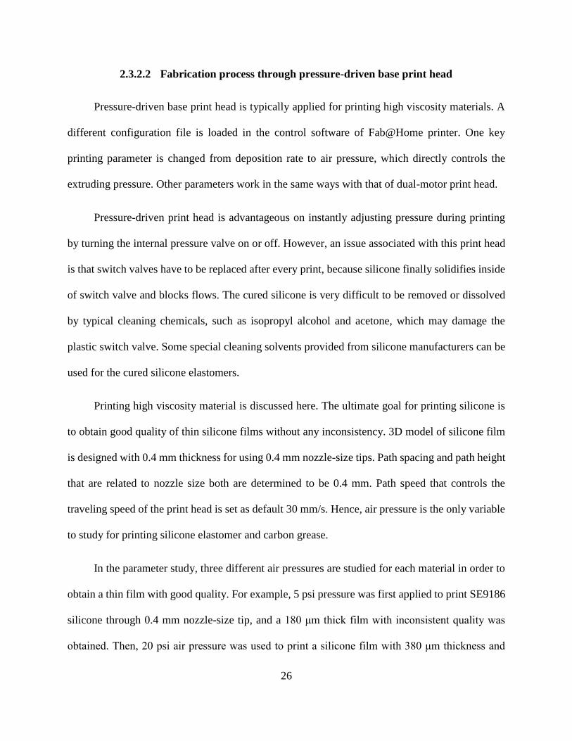
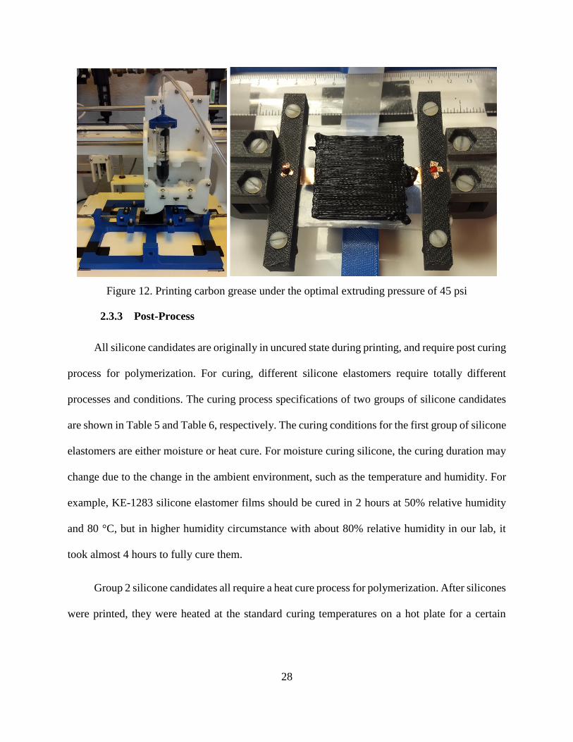
In addition, for printing electrodes on the both sides of dielectric elastomer films, it uses the
same pressure based print head and the same parameter study, as shown in Figure 12 below. The
printed silicone films need to be well aligned from some reference points for precisely printing
symmetric carbon grease electrodes on both sides of films. Carbon grease films need to be thick
for the uniform charge distribution while being stretched. In the parameter study of the print
process for carbon grease, a set of three different air pressure, 40, 45 and 50 psi, were tested to
extrude carbon through 0.4 mm nozzle-size tip. Inconsistent appearance occurs in carbon grease
film with 40 psi extruding pressure, while 45 and 50 psi pressure have more uniform appearances.
However, applying 50 psi pressure makes carbon grease film about 2 mm thick, which is twice of
that under 45 psi pressure. Thus, 45 psi air pressure was determined for printing about 1 mm thick
carbon grease.
28
Figure 12. Printing carbon grease under the optimal extruding pressure of 45 psi
2.3.3 Post-Process
All silicone candidates are originally in uncured state during printing, and require post curing
process for polymerization. For curing, different silicone elastomers require totally different
processes and conditions. The curing process specifications of two groups of silicone candidates
are shown in Table 5 and Table 6, respectively. The curing conditions for the first group of silicone
elastomers are either moisture or heat cure. For moisture curing silicone, the curing duration may
change due to the change in the ambient environment, such as the temperature and humidity. For
example, KE-1283 silicone elastomer films should be cured in 2 hours at 50% relative humidity
and 80 °C, but in higher humidity circumstance with about 80% relative humidity in our lab, it
took almost 4 hours to fully cure them.
Group 2 silicone candidates all require a heat cure process for polymerization. After silicones
were printed, they were heated at the standard curing temperatures on a hot plate for a certain

29
period of time. The specifications of the heat curing process for each silicone candidate is listed in
the Table 6.
Table 5. Curing conditions for Group 1 silicone elastomer from motor-driven print head
KE-1283 KE-3417 KE-3494 Sylgard 170
Curing Type Heat Moisture Moisture Heat
Condition 80 °C 20 °C 20 °C 100 °C
Duration 4 hours 2 hours 6 hours 20 minutes
*Note: Lab humidity is about 80% relative humidity (RH).
Table 6. Curing conditions for Group 2 silicone elastomer from pressure-driven print head
Sylgard 186 SE 9186 LIM 6010 R-2188 R3-1075 236
Curing
Type Heat Heat Heat Heat Heat Heat
Condition 100 °C 100 °C 150 °C 100 °C 100 °C 100 °C
Duration 25 min 60 min 0.5 min 30 min 120 min 120 min
2.3.4 Assembling process for dielectric elastomer actuator
After being printed, all components were manually assembled into a DEA. In the assembling
process, pre-strain is applied by stretching silicone membranes on the rigid frames at a certain
elongation. The round corner copper tapes which can avoid the concentrated charging and a local
dielectric breakdown were attached to the electrodes for connecting to the external voltage source.
The configuration of a circular DEA is shown in Figure 13, including silicone dielectric
elastomer films, carbon conductive grease as electrodes, and circular rigid frames. All components
of the circular DEAs are 3D printed, except that copper tapes are used as electrical wires to connect
the DEA to a voltage supply. The configuration of this circular DEA is designed for testing the
performance of each selected silicone elastomer.

30
Figure 13. The configuration of a circular DEA
For a rectangular DEA as shown in the Figure 8, its configuration includes a silicone film
sandwiched by carbon grease films, two rigid frames for holding DEA, copper wires for
connecting external supply, and a stretching base for adjusting pre-strain condition.
2.4 Characterizations of Printed Materials
In this section, the characteristics of the printed DEA components are discussed. Specifically,
the printed silicone and carbon grease films are the major components in DEA development that
influence performance, while rigid frames and stretching base made of ABS plastic are used to
provide sufficient strength for holding and stretching DEAs. Thus, only silicone and carbon grease
films are studied.
2.4.1 Silicone film
Silicone films have the dominant impact on DEA actuation. Any defects or voids in the
printed silicone film may weaken its material properties. Uniform film thickness is a main indicator
of the printing quality, which was measured for the printed samples of each silicone candidate to
demonstrate the printing quality.
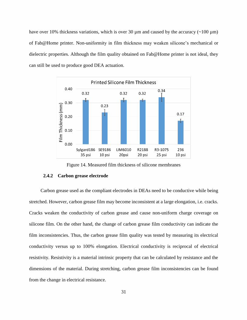
The film thickness of each silicone candidate was measured by using a micrometer at six
different positions. The average value of six measurements for each candidate is shown in the
Figure 14, and error bars show the standard derivations of film thickness. Most of silicone films
31
have over 10% thickness variations, which is over 30 µm and caused by the accuracy (~100 µm)
of Fab@Home printer. Non-uniformity in film thickness may weaken silicone’s mechanical or
dielectric properties. Although the film quality obtained on Fab@Home printer is not ideal, they
can still be used to produce good DEA actuation.
Figure 14. Measured film thickness of silicone membranes
2.4.2 Carbon grease electrode
Carbon grease used as the compliant electrodes in DEAs need to be conductive while being
stretched. However, carbon grease film may become inconsistent at a large elongation, i.e. cracks.
Cracks weaken the conductivity of carbon grease and cause non-uniform charge coverage on
silicone film. On the other hand, the change of carbon grease film conductivity can indicate the
film inconsistencies. Thus, the carbon grease film quality was tested by measuring its electrical
conductivity versus up to 100% elongation. Electrical conductivity is reciprocal of electrical
resistivity. Resistivity is a material intrinsic property that can be calculated by resistance and the
dimensions of the material. During stretching, carbon grease film inconsistencies can be found
from the change in electrical resistance.
32
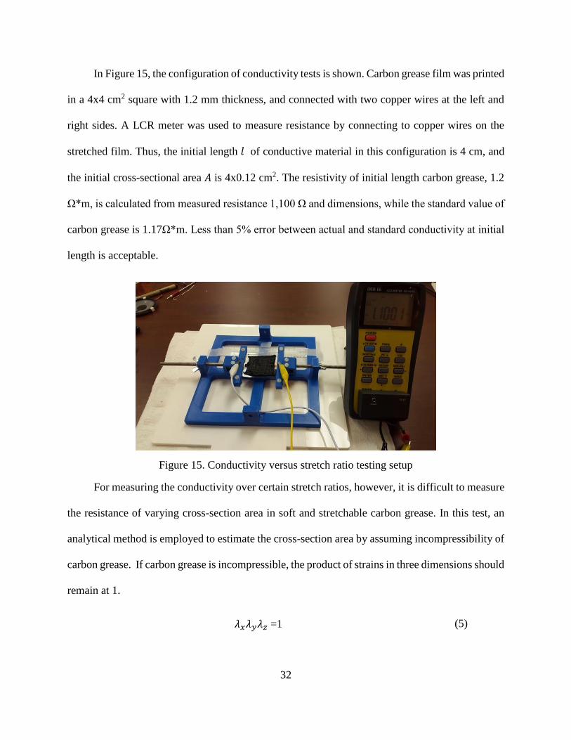
In Figure 15, the configuration of conductivity tests is shown. Carbon grease film was printed
in a 4x4 cm2 square with 1.2 mm thickness, and connected with two copper wires at the left and
right sides. A LCR meter was used to measure resistance by connecting to copper wires on the
stretched film. Thus, the initial length 𝑙 of conductive material in this configuration is 4 cm, and
the initial cross-sectional area 𝐴 is 4x0.12 cm2. The resistivity of initial length carbon grease, 1.2
Ω*m, is calculated from measured resistance 1,100 Ω and dimensions, while the standard value of
carbon grease is 1.17Ω*m. Less than 5% error between actual and standard conductivity at initial
length is acceptable.
Figure 15. Conductivity versus stretch ratio testing setup
For measuring the conductivity over certain stretch ratios, however, it is difficult to measure
the resistance of varying cross-section area in soft and stretchable carbon grease. In this test, an
analytical method is employed to estimate the cross-section area by assuming incompressibility of
carbon grease. If carbon grease is incompressible, the product of strains in three dimensions should
remain at 1.
𝜆𝑥𝜆𝑦𝜆𝑧 =1 (5)

33
In this testing configuration, 𝜆𝑥 is the stretch ratio along the direction of electrical current,
𝜆𝑦𝜆𝑧 is the area stretch ratio of the cross section of conductive material. In the conductivity versus
stretch ratio test, printed carbon grease film was stretched up to 100% by an increment of 20%, so
stretch ratio 𝜆𝑥 is known. Thus, 𝜆𝑦𝜆𝑧 is equal to 1
𝜆𝑥, and cross sectional area at every 20%
increment of 𝜆𝑥 can be calculated by the product of the original area and area stretch ratio. Hence,
conductivity of printed carbon grease at each stretch ratio is finally calculated from the reciprocal
resistivity. All specifications of this conductivity test are listed in the Table 7.
Table 7. Specifications for carbon grease conductivity test
𝑙 Length
(cm)
𝜆𝑥 Length
Stretch Ratio
𝜆𝑦𝜆𝑧 Area
Stretch Ratio
𝐴 Cross section
Area (cm^2)
Resistance
(Ω)
Resistivity
(Ω*m)
Conductivity
(Ω-1*m-1)
4.0E-02 1 1.00 4.8E-05 1000 1.20 0.83
4.8E-02 1.2 0.83 4.0E-05 1400 1.17 0.86
5.6E-02 1.4 0.71 3.4E-05 2000 1.22 0.82
6.4E-02 1.6 0.63 3.0E-05 3500 1.64 0.61
7.2E-02 1.8 0.56 2.7E-05 5400 2.00 0.50
8.0E-02 2 0.50 2.4E-05 7100 2.13 0.47
Compared to carbon grease standard conductivity from the given resistivity, the printed
carbon grease film can provide 100% conductivity under 40% elongation with an acceptable error
of below 5% based on the Figure 16. After being stretched over 40%, carbon grease film has a
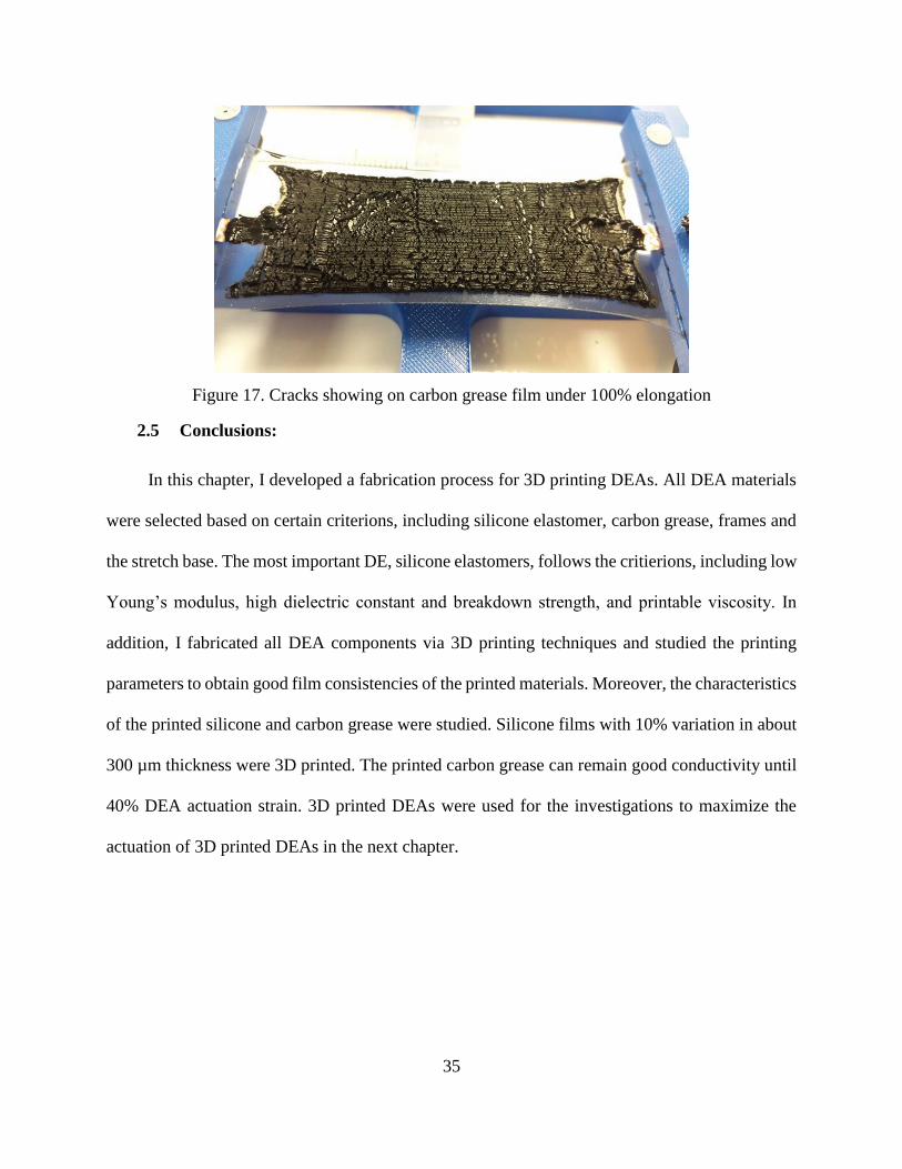
significant change in conductivity, which indicates the film inconsistencies. In addition, film
inconsistencies, like cracks, were found on the printed carbon grease film at 100% elongation,
shown in the Figure 17. In summary, the film inconsistency, like cracks, is the reason why
conductivity of carbon grease is weakened at large elongation.

34
To explain, cracks in the carbon grease electrode cause changes in electrical resistance,
because cracks generate non-conductive gaps in electrode. The change of electrical resistance can
be reflected to the change of electrical resistivity and the change of electrical conductivity,
assuming that carbon grease and cracks are considered as one electrode. In addition, the non-
conductive gaps in the electrode cause the non-uniform charging, which means that the DEA is
partially charged. Thus, DEA actuation is weakened by the partial charging when cracks occur in
electrode. Hence, this conductivity versus stretch ratio test is essential to know until which
elongation the printed carbon grease electrode will not weaken DEA actuation.
The result shows that the printed carbon grease film is capable of providing good
conductivity within 40% elongation. It indicates that the printed carbon grease film on DEAs will
not weaken DEA actuation within 40% actuation strain.
Figure 16. Conductivity result of printed carbon grease versus up to 100% elongation
35
Figure 17. Cracks showing on carbon grease film under 100% elongation
2.5 Conclusions:
In this chapter, I developed a fabrication process for 3D printing DEAs. All DEA materials
were selected based on certain criterions, including silicone elastomer, carbon grease, frames and
the stretch base. The most important DE, silicone elastomers, follows the critierions, including low
Young’s modulus, high dielectric constant and breakdown strength, and printable viscosity. In
addition, I fabricated all DEA components via 3D printing techniques and studied the printing
parameters to obtain good film consistencies of the printed materials. Moreover, the characteristics
of the printed silicone and carbon grease were studied. Silicone films with 10% variation in about
300 µm thickness were 3D printed. The printed carbon grease can remain good conductivity until
40% DEA actuation strain. 3D printed DEAs were used for the investigations to maximize the
actuation of 3D printed DEAs in the next chapter.

36
3 DIELECTRIC ELASTOMER ACTUATOR PERFORMANCE TESTS
3.1 Introduction
After silicone DEA fabrication, performance tests of these 3D printed DEAs were conducted
to select the largest actuation DEA for soft robotic development. To obtain large DEA actuation,
both pre-strain condition and DEA configuration play important roles, and their impacts on DEA
actuation are investigated in the following sections, respectively. For example, the investigation
of pre-strain condition with key material properties, such as Young’s modulus and dielectric
properties, was completed to obtain large actuation for each silicone DEA. The quantitative
relationships between silicone’s material properties and pre-strain were used to estimate DEA
actuation and validated with the empirical results. In addition, different DEA configurations, like
circular and rectangular types, present different DEA actuation due to their different boundary
constraints. Empirical and modeling results were obtained to discuss the impact of DEA
configuration in order to employ the DEA configuration with the largest actuation in soft robot.
3.2 Investigation of the Effect of Pre-strain Condition
Based on the literature review of pre-strain condition in the first chapter, pre-strain can
enhance DEA actuation by reducing Young’s modulus and increasing dielectric breakdown
strength of dielectric elastomer. The largest DEA actuation strain of 80% in the literature was
achieved by applying large pre-strain of 175% on Dow Corning Sylgard 186 silicone elastomer,
which was fabricated through the conventional spin-coating method. However, it was reported that
the excessive pre-strain would stiffen dielectric elastomer which weakens DEA actuation.

37
Hence, understanding the effects of pre-strain on dielectric elastomers key properties is
helpful to find the optimal pre-strain for maxmizing the DEA actuation. For example, it was
reported that pre-strain condition in acrylic dielectric elastomer simultaneously increases dielectric
breakdown strength while decreases dielectric constant [38]. Thus, excessive pre-strain would
weaken acrylic DEA actuation from this contradictory effect.
For silicone dielectric elastomers, pre-strain condition was found reducing Young’s modulus
and increasing dielectric breakdown strength. However, the relationship between pre-strain
condition and silicone’s dielectric constant has not been explained well in the literature. It is
important to understand the effects of pre-strain condition on relevant silicone properties in order
to find the optimal pre-strain condition for obtaining the largest actuation. Hence, in this section,
some important material properties, such as Young’s modulus, dielectric constant and breakdown
strength, versus stretch ratios are studied for understanding the pre-strain effects for each silicone
candidate.
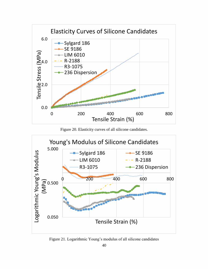
3.2.1 Tensile tests
For silicone elastomer candidates, knowing their elasticity curve are essential for
determining the pre-strain condition that reduces Young’s modulus. In this test, ISO 37:2011 test
standard (Rubber, vulcanized or thermoplastic – Determination of tensile stress-strain properties)
was used to obtain the stress-strain curve. Dumbbell-shaped specimens are stretched in a tensile
tester at a constant rate, based on ISO 37:2011 standard. In addition, the types 1, 2 and 1A
dumbbells specimens with different dimensions are more precise for measuring tensile stress
versus strain until the break. Considering the ease of fabrication, the type 2 dumbbell test specimen
with a minimum 2 mm thickness of narrow portion was employed, as shown in the Figure 18, and
other dimensions are listed in the Table 8.
38
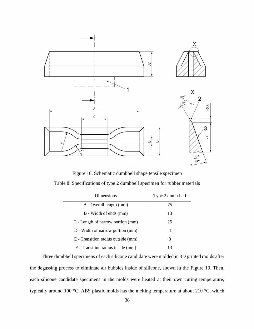
Figure 18. Schematic dumbbell shape tensile specimen
Table 8. Specifications of type 2 dumbbell specimen for rubber materials
Dimensions Type 2 dumb-bell
A - Overall length (mm) 75
B - Width of ends (mm) 13
C - Length of narrow portion (mm) 25
D - Width of narrow portion (mm) 4
E - Transition radius outside (mm) 8
F - Transition radius inside (mm) 13
Three dumbbell specimens of each silicone candidate were molded in 3D printed molds after
the degassing process to eliminate air bubbles inside of silicone, shown in the Figure 19. Then,
each silicone candidate specimens in the molds were heated at their own curing temperature,
typically around 100 °C. ABS plastic molds has the melting temperature at about 210 °C, which

39
doesn’t cause any issue in the heat curing process. Finally, three dumbbell specimens were made
for each of the six silicone candidates listed in Table 2 and were tested on a tensile tester as shown
in Figure 19. This tester can automatically store tensile force and elongation, and tensile stress is
calculated by dividing the measured force by the cross-sectional area. Thus, elasticity curves of
tensile stress and strain of six silicone candidates were obtained and plotted in the Figure 20.
Obviously, these six silicone candidates all have the capability of being stretched over 300%
elongation, which shows good potential for large DEA actuation.
(a) (b)
Figure 19. (a) An example of molding 236 silicone elastomer (b) 236 silicone dumbbell
specimen being tensile tested
40
Figure 20. Elasticity curves of all silicone candidates.
Figure 21. Logarithmic Young’s modulus of all silicone candidates
0.0
2.0
4.0
6.0
0 200 400 600 800
Ten
sile
Str
ess
(MPa
)
Tensile Strain (%)
Elasticity Curves of Silicone Candidates
Sylgard 186SE 9186LIM 6010R-2188R3-1075236 Dispersion
0.050
0.500
5.000
0 200 400 600 800
Loga
rith
mic
Yo
un
g's
Mo
du
lus
(MPa
)
Tensile Strain (%)
Young's Modulus of Silicone Candidates
Sylgard 186 SE 9186
LIM 6010 R-2188
R3-1075 236 Dispersion

41
Based on the stress-strain curve, the change of Young’s modulus with strain is shown in the
Figure 21, which demonstrates the non-linear hyper-elasticity of silicone. These silicone
candidates share the similar hyper-elasticity that the globally lowest Young’s modulus occurs in
the middle region of elasticity curve. Hence, the applicable pre-strain for reducing silicone
elastomers’ Young’s modulus should be in the middle region of their elasticity curves.
In addition, the measured Young’s modulus of Sylgard 186 silicone varies from 0.18 MPa
at zero pre-strain, while in the literature some papers reported the constant Sylgard 186 silicone
Young’s moduli from 1.2 MPa to 0.6 MPa [39-41]. There could be two possible reasons for this
discrepancy. One is the Young’s modulus was measured by compression test in the cited references
while we did a standard tension test using ISO 37 standard, which may cause the measurement
difference due to the hyper-elasticity of Sylgard 186. The other possible reason is that we observed
some slippery of the sample from the grip during the tensile test, which may have increased the
tensile strain and thus lead to a smaller Young’s modulus.
After elasticity and Young’s modulus with strain curves were measured for each silicone
candidates, determining the applicable pre-strain is the ultimate goal of tensile test. Dow Corning
Sylgard 186 silicone is used to exemplify the approach in the Figure 22. The change of Young’s
modulus versus tensile strain of Sylgard 186 silicone is presented, and the variation of its Young’s
modulus is apparent. First step is to record the initial Young’s modulus of 0.19 MPa and find the
lowest value of 0.08 MPa among the entire progression. Thus, the maximum reduction from the
initial is about 0.11 MPa.
The pre-strain at the lowest young’s modulus may not be the optimal one to maximize the
DEA actuation. It is known that DEA actuation depends on three material properties of silicone
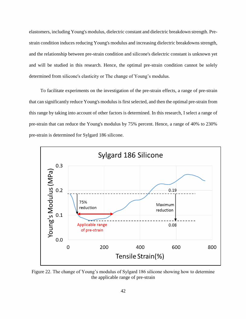
42
elastomers, including Young's modulus, dielectric constant and dielectric breakdown strength. Pre-
strain condition induces reducing Young's modulus and increasing dielectric breakdowns strength,
and the relationship between pre-strain condition and silicone's dielectric constant is unknown yet
and will be studied in this research. Hence, the optimal pre-strain condition cannot be solely
determined from silicone's elasticity or The change of Young’s modulus.
To facilitate experiments on the investigation of the pre-strain effects, a range of pre-strain
that can significantly reduce Young's modulus is first selected, and then the optimal pre-strain from
this range by taking into account of other factors is determined. In this research, I select a range of
pre-strain that can reduce the Young's modulus by 75% percent. Hence, a range of 40% to 230%
pre-strain is determined for Sylgard 186 silicone.
Figure 22. The change of Young’s modulus of Sylgard 186 silicone showing how to determine
the applicable range of pre-strain

43
Based on this approach, all applicable ranges of pre-strain conditions of six silicone
candidates are obtained, as shown in the Table 9, as well as the initial, the lowest and 80% reduced
values of Young’s modulus. In general, 40% to 200% applicable pre-strain is obtained to reduce
about 40% Young’s modulus for each silicone candidate.
Table 9. Specifications of elasticity curve for each silicone candidate
Initial Young’s
modulus (Mpa)
lowest Young’s
modulus (Mpa)
75% reduced
Y. modulus
Pre-strain
Range (%)
Y. modulus
Reduction
Sylgard186 0.186 0.080 0.101 40~230 45.7%
SE9186 1.493 0.724 0.878 60~370 41.2%
LIM6010 0.146 0.088 0.099 40~180 31.9%
R-2188 0.334 0.187 0.217 40~170 35.2%
R3-1075 1.738 0.669 0.883 40~390 49.2%
236 0.370 0.199 0.233 40~240 36.9%
Although the applicable range of pre-strain is determined by the change of Young’s modulus
versus stretch ratios, the optimal pre-strain condition for the maximum DEA actuation is also
affected by other key material properties, such as dielectric constant and breakdown strength. If
the impacts of pre-strain on silicone’s mechanical and dielectric properties have opposite effects
on increasing the DEA actuation strain, like acrylic elastomers, the optimal pre-strain for the
largest silicone DEA actuation may not be obtained at the largest strain in the applicable range. To
clarify, it was reported it the literature that increasing pre-strain reduced acrylic’s Young’s
modulus and increased dielectric breakdown strength to enhance DEA actuation while it decreased
dielectric constant weakening DEA actuation. Thus, the largest pre-strain in the applicable range
may not be the optimal one for obtaining the largest DEA actuation.
Hence, the investigations of the relationship between pre-strain condition and silicone’s
dielectric properties are essential to find the optimal pre-strain. The experimental setups and results
for dielectric constant and dielectric breakdown strength will be discussed in the next two sections.
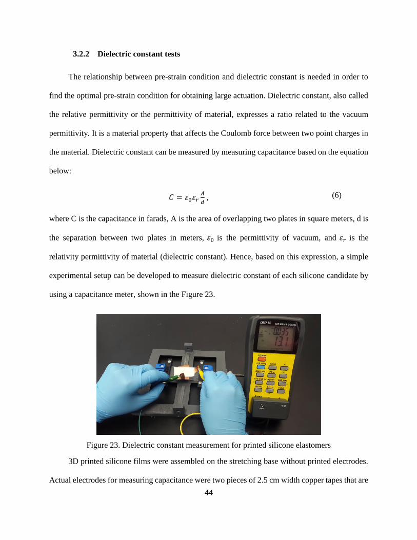
44
3.2.2 Dielectric constant tests
The relationship between pre-strain condition and dielectric constant is needed in order to
find the optimal pre-strain condition for obtaining large actuation. Dielectric constant, also called
the relative permittivity or the permittivity of material, expresses a ratio related to the vacuum
permittivity. It is a material property that affects the Coulomb force between two point charges in
the material. Dielectric constant can be measured by measuring capacitance based on the equation
below:
𝐶 = 𝜀0𝜀𝑟𝐴
𝑑 , (6)
where C is the capacitance in farads, A is the area of overlapping two plates in square meters, d is
the separation between two plates in meters, 𝜀0 is the permittivity of vacuum, and 𝜀𝑟 is the
relativity permittivity of material (dielectric constant). Hence, based on this expression, a simple
experimental setup can be developed to measure dielectric constant of each silicone candidate by
using a capacitance meter, shown in the Figure 23.
Figure 23. Dielectric constant measurement for printed silicone elastomers
3D printed silicone films were assembled on the stretching base without printed electrodes.
Actual electrodes for measuring capacitance were two pieces of 2.5 cm width copper tapes that are

45
orthogonal to each other, and they stick well on the adhesive silicone surface. Thus, the
overlapping area of 2.5x2.5 cm2 was fixed for dielectric constant measurements versus up to 100%
stretch ratio. This measurement method was validated with standard dielectric constant of R-2188
silicone candidate provided by the supplier. The measured dielectric constant of 2.95 is
approximate to the standard value of 2.9 of R-2188 silicone, and the measurement error is less than
2%. Hence, this method is accurate for measuring dielectric constant of silicone membranes.
Dielectric constant versus stretch ratio measurements were conducted on six silicone
candidates from 0% to 100% elongation at an increment of 10% elongation. First of all, thickness
of silicone films at each stretch ratio was measured by using a micrometer. Then, copper films
were attached to the both sides of silicone films at different stretch ratios, respectively. Finally,
copper wires were connected to a DE-5000 LCR meter by using alligator clamps, and the average
capacitance of three measurements was taken.
The empirical dielectric constant is calculated from the capacitance expression in equation
6. Dielectric constants of six silicone candidates versus stretch ratios are shown in the Figure 24
below. It indicates that increasing stretch ratio increases dielectric constants for all silicone
candidates with some fluctuations. In addition, this relationship between silicone’s dielectric
constant and pre-strain is opposite to that of acrylic elastomer. More importantly, the increasing
tendency of dielectric constant versus stretch ratio is positive to produce larger actuation strain.
From these increasing tendencies, the dielectric constants of all candidates increase about 20% at
100% stretch ratio.

46
Figure 24. Measured dielectric constant versus up to 100% elongation for each silicone candidate
In addition, four silicone films, R2188, 236, R3-1075 and SE9186, broke until 100%
elongation during dielectric constant measurements, while they should have the standard
elongation at break larger than 300%. These four silicone films have something in common, such
as relatively high Young’s modulus shown in the Figure 21 and relatively large variation in film
thickness shown in the Figure 14. The reason of breaking at early elongation is very likely that
large variation in film thickness causes stress concentration at thin places while silicone films are
being stretched. The stress concentration at thin places actually performs larger elongation than
the given pre-strain and even approximate to their elongation at break. This issue also happened
in the dielectric breakdown strength measurements and DEA behavior tests. Even though there are
large variations in silicone film thickness, the feasible elongations for all silicone films were still
in the applicable range of pre-strain condition during this test. It means that silicone DEAs with
good pre-strain can be obtained in this research.
47
3.2.3 Dielectric breakdown strength
Dielectric breakdown strength describes the maximum voltage applied to dielectric materials
with certain thickness until electrical breakdown. Dielectric breakdown strength is a critical to
DEA actuation because it limits the voltage-dependent Maxwell pressure. Pure silicone elastomer
has breakdown strength about 20 kV/mm. Commercial silicone products add different types of
fillers to enhance the desired properties for varying applications. These fillers may enhance or
weaken silicone’s dielectric breakdown strength. In addition, from literature about silicone’s
dielectric breakdown strength, pre-strain condition has a significant impact on increasing dielectric
breakdown, which is able to generate more Maxwell pressure for larger DEA actuation strain. Thus,
in this section, the quantitative relationship between silicone’s dielectric breakdown strength and
stretch ratios is investigated.
In this research, ISEG THQ 30 kV dual-channel High-Voltage (HV) supply was used to
measure the dielectric breakdown strength of silicone films, as well as testing DEA actuation strain.
In the experimental setup of HV test, shown in the Figure 25, a rectangular DEA with circular
electrodes is assembled on the stretching base. HV and ground cables with metallic rod head are
inserted in holes of rigid frames, which are designed for power connection and covered by copper
tape, and connect to the front and back compliant electrodes, respectively.
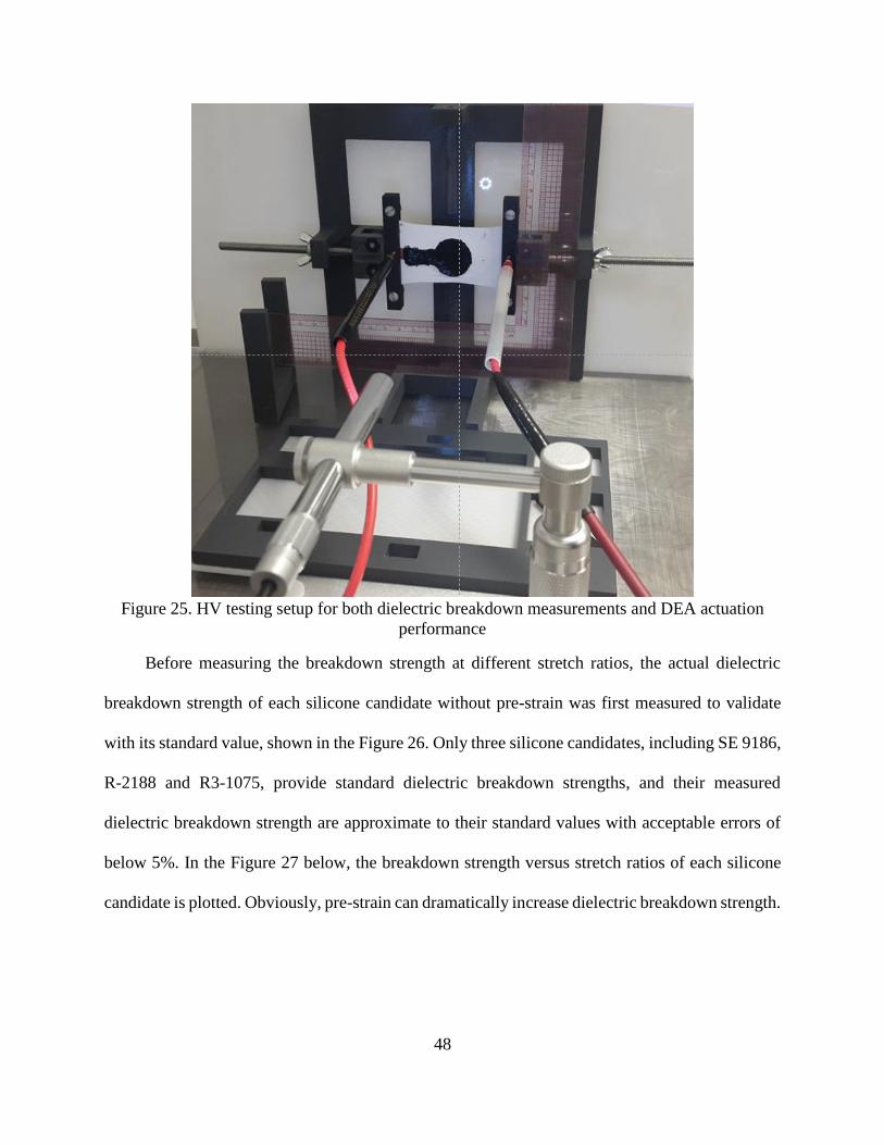
48
Figure 25. HV testing setup for both dielectric breakdown measurements and DEA actuation
performance
Before measuring the breakdown strength at different stretch ratios, the actual dielectric
breakdown strength of each silicone candidate without pre-strain was first measured to validate
with its standard value, shown in the Figure 26. Only three silicone candidates, including SE 9186,
R-2188 and R3-1075, provide standard dielectric breakdown strengths, and their measured
dielectric breakdown strength are approximate to their standard values with acceptable errors of
below 5%. In the Figure 27 below, the breakdown strength versus stretch ratios of each silicone
candidate is plotted. Obviously, pre-strain can dramatically increase dielectric breakdown strength.

49
Figure 26. Validation of standard and measured dielectric breakdown strength
Figure 27. . Measured dielectric breakdown strength versus different stretch ratios
In addition, the increasing rates of breakdown strength from initial to 40% are listed in Table
10, and the increasing rates at 100% pre-strain condition of all silicone candidates are estimated
based on the tendency of initial 40% pre-strain. The estimated rates at 100% pre-strain condition
can be used to predict the DEA actuation strains for six silicone candidates.

50
Table 10. Estimated increasing rate for each silicone candidate under 100% pre-strain
Pre-Strain
(%)
Breakdown Strength
(kV/mm)
Increasing Rate
(%)
Sylgard 186
0 26.7 -
40 30.0 12.4%
80 44.7 67.5%
100 - estimated 54.0 80%
SE 9186
0 23.6 -
40 40.7 72.5%
100 - estimated 66.3 181.1%
LIM 6010
0 26.7 -
40 42.5 74.9%
80 62.5 157.2%
100 - estimated 72.0 196.5%
R2188
0 20.3 -
40 47.6 140.0%
100 - estimated 91.4 350.0%
R3-1075
0 48.9 -
40 59.5 21.7%
100 - estimated 75.5 54.3%
236 silicone DEAs without pre-strain and with 40% pre-strain conditions both failed due to
dielectric breakdown. Their 5.6 and 7.9 kV/mm actual dielectric breakdown strengths are much
lower than 14.8 kV/mm breakdown strength of a bare 236 silicone membrane without pre-strain
condition. In addition, no leaking sparks or physical breakdowns were observed. Thus, the failure
reason of 236 silicone DEA is very likely that 236 silicone’s dielectric breakdown strength was
weakened by other materials in contact, especially carbon grease. Other evidence shows that 236
silicone surface became crumbled after carbon grease was deposited on the silicone for a short
period of time. Hence, it is very possible that carbon grease weakened 236 silicone’s dielectric
breakdown strength. Since carbon grease is selected for its good conductivity at large elongation,
236 silicone will not be applied in the DEA in contact with carbon grease.
51
3.2.4 Estimation for Dielectric Elastomer Actuator Behavior
In this section, a validated analytical method is also presented to estimate DEA actuation
strain with pre-strain. All quantitative relationships between pre-strain and key material properties
of each silicone elastomer at the feasible pre-strain range have been measured, including Young’s
modulus, dielectric constant and breakdown strength. The actuation strain of each silicone
candidate can be calculated based on the physical principles of electrostatics and solid mechanics.
Specifically, maximum Maxwell pressure at certain pre-strain condition is obtained from the
measured dielectric constant and breakdown strength at the same pre-strain. By assuming that
silicone is an incompressible and isotropic material, its mechanical deformation is calculated from
Hooke’ Law expressions:
𝜀𝑥𝑥 =1
𝐸[𝜎𝑥𝑥 − 𝛾(𝜎𝑦𝑦 + 𝜎𝑧𝑧)]
𝜀𝑦𝑦 =1
𝐸[𝜎𝑦𝑦 − 𝛾(𝜎𝑥𝑥 + 𝜎𝑧𝑧)]
𝜀𝑧𝑧 =1
𝐸[𝜎𝑧𝑧 − 𝛾(𝜎𝑥𝑥 + 𝜎𝑦𝑦)]
(12)
where 𝜀𝑥𝑥, 𝜀𝑦𝑦 and 𝜀𝑧𝑧 are the strain in the direction of x, y and z axis, 𝜎𝑥𝑥, 𝜎𝑦𝑦 and 𝜎𝑧𝑧 are the
stress in the direction of x, y and z axis, E is Young's modulus, 𝛾 is Poisson's ratio that is
approximate to 0.5 for silicone rubber.
3.2.4.1 Validation with experimental results
By applying measured material properties at 40% stretch ratio, the DEA actuation strain of
each silicone candidates can be estimated through this analytical method. The estimated results of
five silicone candidates were compared to their empirical actuation strains in order to validate the
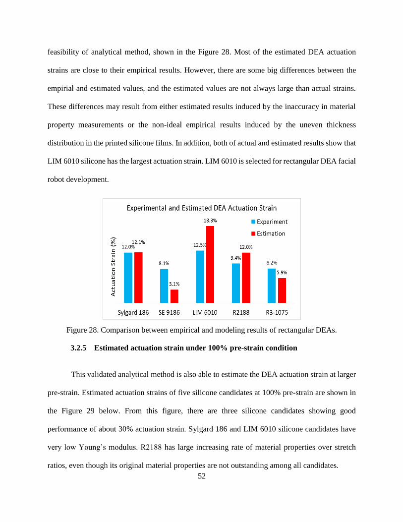
52
feasibility of analytical method, shown in the Figure 28. Most of the estimated DEA actuation
strains are close to their empirical results. However, there are some big differences between the
empirial and estimated values, and the estimated values are not always large than actual strains.
These differences may result from either estimated results induced by the inaccuracy in material
property measurements or the non-ideal empirical results induced by the uneven thickness
distribution in the printed silicone films. In addition, both of actual and estimated results show that
LIM 6010 silicone has the largest actuation strain. LIM 6010 is selected for rectangular DEA facial
robot development.
Figure 28. Comparison between empirical and modeling results of rectangular DEAs.
3.2.5 Estimated actuation strain under 100% pre-strain condition
This validated analytical method is also able to estimate the DEA actuation strain at larger
pre-strain. Estimated actuation strains of five silicone candidates at 100% pre-strain are shown in
the Figure 29 below. From this figure, there are three silicone candidates showing good
performance of about 30% actuation strain. Sylgard 186 and LIM 6010 silicone candidates have
very low Young’s modulus. R2188 has large increasing rate of material properties over stretch
ratios, even though its original material properties are not outstanding among all candidates.

53
Figure 29. Estimated actuation strain of rectangular silicone DEAs under 100% pre-strain
condition via this analytical method
3.2.6 Result discussion
Above, the impacts of pre-strain condition on three key material properties have been
investigated, including Young’s modulus, dielectric constant and breakdown strength. Young’s
modulus of each silicone candidate reduces about 40% upon the application of 40% to 200% pre-
strain condition, which can produce larger mechanical deformation. In addition, increasing pre-
strain increases silicone dielectric constant and dielectric breakdown strength, which can generate
larger Maxwell pressure. Therefore, the application of pre-strain condition is able to enhance large
DEA actuation. Then, based on the pre-strain and material property investigations, the optimal
pre-strain of each silicone candidate is determined to be the maximum value in the applicable
range, typically 200%.
Moreover, from the quantitative relationships between pre-strain and key material properties,
40% maximum DEA actuation at 100% pre-strain was estimated from the coupling physics.
54
3.3 Study of Different Dielectric Elastomer Actuator Configurations
In this section, a comparison study of different DEA configurations is discussed. The impacts
of DEA configurations, like circular and rectangular type actuators, have not been well explained
to DEA actuation in the literature. The difference between rectangular and circular DEAs may be
due to different boundary constraints applied to dielectric elastomer membrane. Two independent
rigid frames in rectangular type DEA on the opposite sides hold the pre-stretched elastomer
membrane, which provide free boundary constraint in other two edges. While a circular rigid frame
in circular type DEA provides the isotropically fixed boundary constraints on the entire edge. Thus,
it brings a new research question to my DEA development: do boundary constraints affect DEA
behavior for producing larger actuation? By hyprothesizing that less boundary constraint can
produce larger DEA actuation, rectangular and circular DEA configurations with different
boundary constraints are studied via experiment and simulation.
In addition, DEA actuation for all silicone candidates are tested to select the best candidate
with the largest actuation strain for DEA robotic development. DEA actuation tests were
conducted in HV tests. Initial status and maximum actuation of DEAs were video-captured using
a digital USB microscope, and vertical and horizontal actuation strain were measured via the image
processing method. Finally, the results of actual DEA actuation strains and estimated value will
be discussed at the end of this section.
3.3.1 DEA actuation strain measurements by image processing
An image processing method via MATLAB was developed to measure DEA actuation strain.
DEA actuation strain was measured by calculating the changing rate of the electrode dimensions
at the maximum actuation and the initial status, and two images of initial status and maximum

55
actuation are desired. After converting to black/white images, they can be represented by two
binary matrices. The ratio between the sum of black pixels in one dimension in the maximum
actuation image and the sum of black pixels in the same dimension in the initial status image can
represent DEA actuation strain in that direction. In addition, an experimental validation was done
to present the accuracy of this method.
A simple experimental setup was used to validate the results from MATLAB image
processing method with actual elongation, shown in Figure 30. A silicone film with a 4x1 cm2
marker was assembled on the stretching case, and a ruler was fixed on one side of silicone film to
show the actual elongation. A high-resolution camera was also used to film the stretching process,
and in Figure 30 two images of initial status and 60% elongation were snapped from the film.
Using the developed image processing method, an average elongation of 60.3% along the
stretching dimension was measured. A 0.5% error between the actual and measured strains is
acceptable. Therefore, this MATLAB image processing method shows in good agreement with
actual values, and is feasible for DEA actuation strain measurement.
Figure 30. Experimental validation for MATLAB Image Processing method

56
3.3.2 Circular dielectric elastomer actuator behavior
Circular DEAs, made of group 1 silicone candidates, were 3D printed. All circular DEA
actuation behaviors were tested to select the best one with the largest actuation for later robotic
development. The initial status and maximum actuation are shown in Figure 31. The maximum
strain for each silicone DEA was measured via the image processing method, shown in Figure 32.
Among all silicone elastomers, KE-1283 silicone DEA under 20% pre-strain condition shows the
largest maximum strain of 5.9%, which is about 10 times of actuation strain of 3D printed acrylic
DEA in literature. KE-1283 silicone was selected as the dielectric elastomer film for the circular
DEA facial robot.
In addition, 20% and 30% pre-strain conditions were successfully applied to KE-3494
silicone DEAs. The results show that higher pre-strain induced larger planar deformation and
smaller normal deformation (perpendicular to the planar film). It indicates that increasing pre-
strain is able to produce large DEA actuation in planar direction.
Maximum

57
Figure 31. Circular silicone DEA performances
a). 1.2x pre-stretched Sylgard 170 silicone DEAs show 1.4% maximum strain and slightly normal dimension deformation
b). 1.2x pre-stretched KE-1283 silicone DEAs show 5.9% maximum strain
c). 1.2x pre-stretched KE-3417 silicone DEAs show about 2.1% maximum strain
d). 1.2x pre-stretched KE-3494 silicone DEAs show about 1.8% strain and obvious normal deformation
e). 1.3x pre-stretched KE-3494 silicone DEAs show about 2.4% maximum strain and slightly normal deformation
Initial Maximum Initial
Initial Initial
Initial
Maximum
Maximum Maximum
Maximum
Maximum
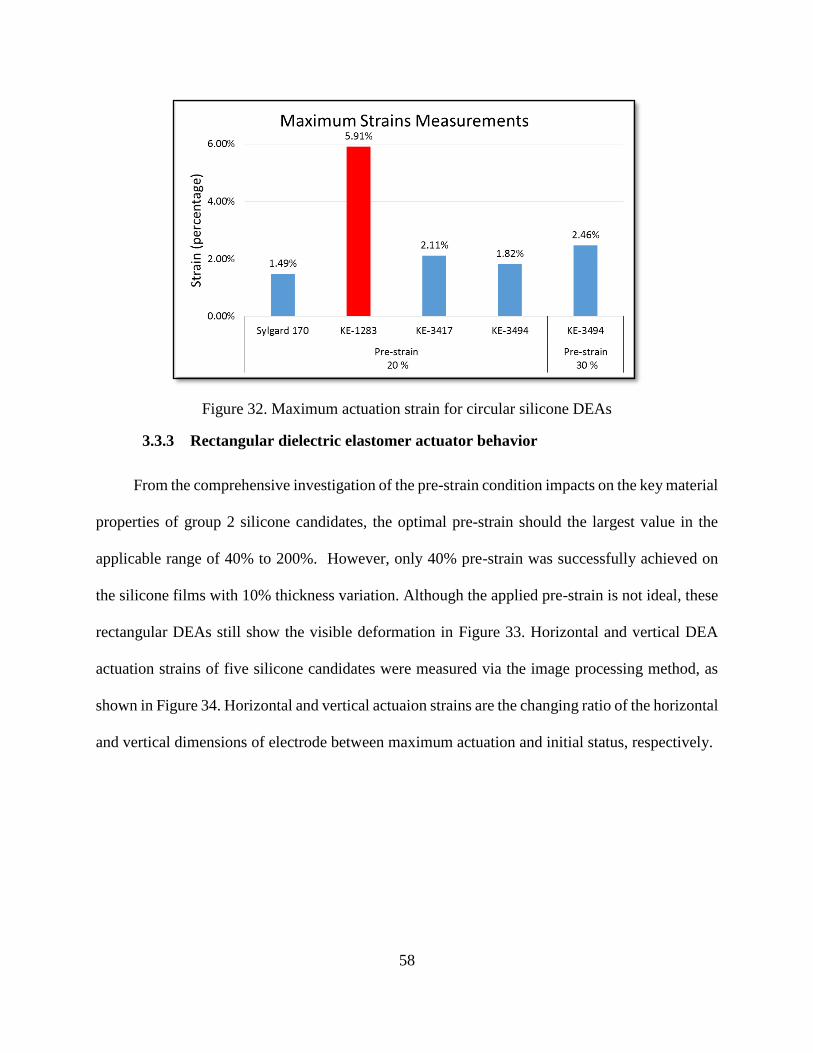
58
Figure 32. Maximum actuation strain for circular silicone DEAs
3.3.3 Rectangular dielectric elastomer actuator behavior
From the comprehensive investigation of the pre-strain condition impacts on the key material
properties of group 2 silicone candidates, the optimal pre-strain should the largest value in the
applicable range of 40% to 200%. However, only 40% pre-strain was successfully achieved on
the silicone films with 10% thickness variation. Although the applied pre-strain is not ideal, these
rectangular DEAs still show the visible deformation in Figure 33. Horizontal and vertical DEA
actuation strains of five silicone candidates were measured via the image processing method, as
shown in Figure 34. Horizontal and vertical actuaion strains are the changing ratio of the horizontal
and vertical dimensions of electrode between maximum actuation and initial status, respectively.
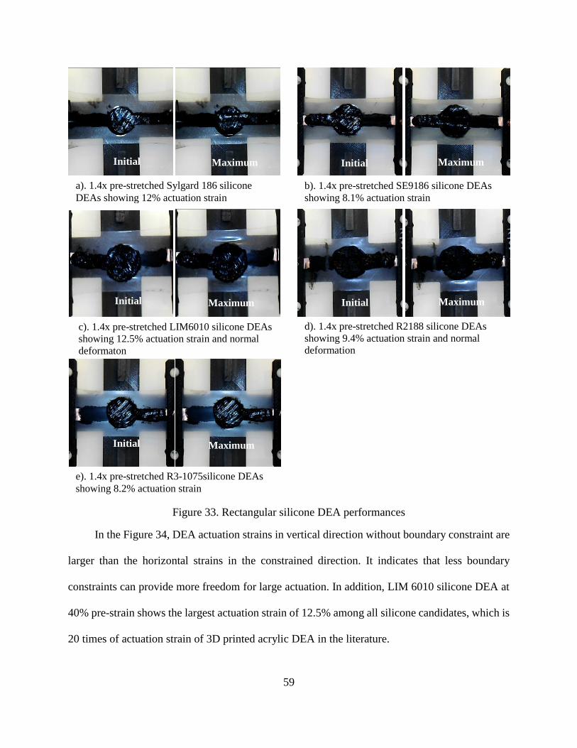
59
Figure 33. Rectangular silicone DEA performances
In the Figure 34, DEA actuation strains in vertical direction without boundary constraint are
larger than the horizontal strains in the constrained direction. It indicates that less boundary
constraints can provide more freedom for large actuation. In addition, LIM 6010 silicone DEA at
40% pre-strain shows the largest actuation strain of 12.5% among all silicone candidates, which is
20 times of actuation strain of 3D printed acrylic DEA in the literature.
a). 1.4x pre-stretched Sylgard 186 silicone
DEAs showing 12% actuation strain b). 1.4x pre-stretched SE9186 silicone DEAs
showing 8.1% actuation strain
c). 1.4x pre-stretched LIM6010 silicone DEAs
showing 12.5% actuation strain and normal
deformaton
d). 1.4x pre-stretched R2188 silicone DEAs
showing 9.4% actuation strain and normal
deformation
e). 1.4x pre-stretched R3-1075silicone DEAs
showing 8.2% actuation strain
Initial Maximum Initial Maximum
Initial Maximum Initial Maximum
Initial Maximum
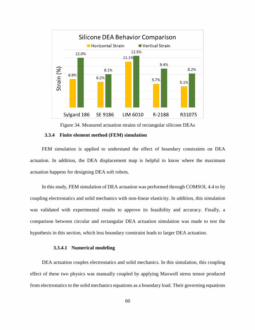
60
Figure 34. Measured actuation strains of rectangular silicone DEAs
3.3.4 Finite element method (FEM) simulation
FEM simulation is applied to understand the effect of boundary constraints on DEA
actuation. In addition, the DEA displacement map is helpful to know where the maximum
actuation happens for designing DEA soft robots.
In this study, FEM simulation of DEA actuation was performed through COMSOL 4.4 to by
coupling electrostatics and solid mechanics with non-linear elasticity. In addition, this simulation
was validated with experimental results to approve its feasibility and accuracy. Finally, a
comparison between circular and rectangular DEA actuation simulation was made to test the
hypothesis in this section, which less boundary constraint leads to larger DEA actuation.
3.3.4.1 Numerical modeling
DEA actuation couples electrostatics and solid mechanics. In this simulation, this coupling
effect of these two physics was manually coupled by applying Maxwell stress tensor produced
from electrostatics to the solid mechanics equations as a boundary load. Their governing equations
61
and constitutive laws are discussed in detail, respectively. In addition, boundary conditions of the
DEA model is also discussed.
3.3.4.1.1 Electrostatics
Electrostatics describes the physical phenomena of the stationary electric charges. DEAs
apply the electrostatic pressure or Maxwell pressure as the external load to compress the soft
dielectric elastomer membranes for obtaining the transverse deformation. Maxwell pressure
aforementioned in the equation 1 in the first chapter is the constitutive laws of the electrostatics in
DEA actuation. The governing equations of the electrostatics thoughout the DEA can be expressed
as:
𝐸 = −∇𝑉
and ∇𝐸 =𝜌𝑒
𝜀0
(7)
(8)
where 𝐸 is the electric field, 𝑉 is the electric potential or the applied voltage, 𝜌𝑒 is the electric
charge density and 𝜀0 is the permittivity of free space (𝜀0 = 8.8542e-12 C2/Nm2 ). The Maxwell
stress tensor at each element node of the electrodes is calculated based on these governing
equations, and then applied to the structural mechanics of silicone elastomers.
3.3.4.1.2 Solid mechanics
Upon the application of voltage to the electrodes, Maxwell pressure induces the transverse
strain for DEA actuation. The governing equation of each element node in the solid mechanics is
described:
−∇ ∗ 𝜎 = 𝐹𝑣 (9)
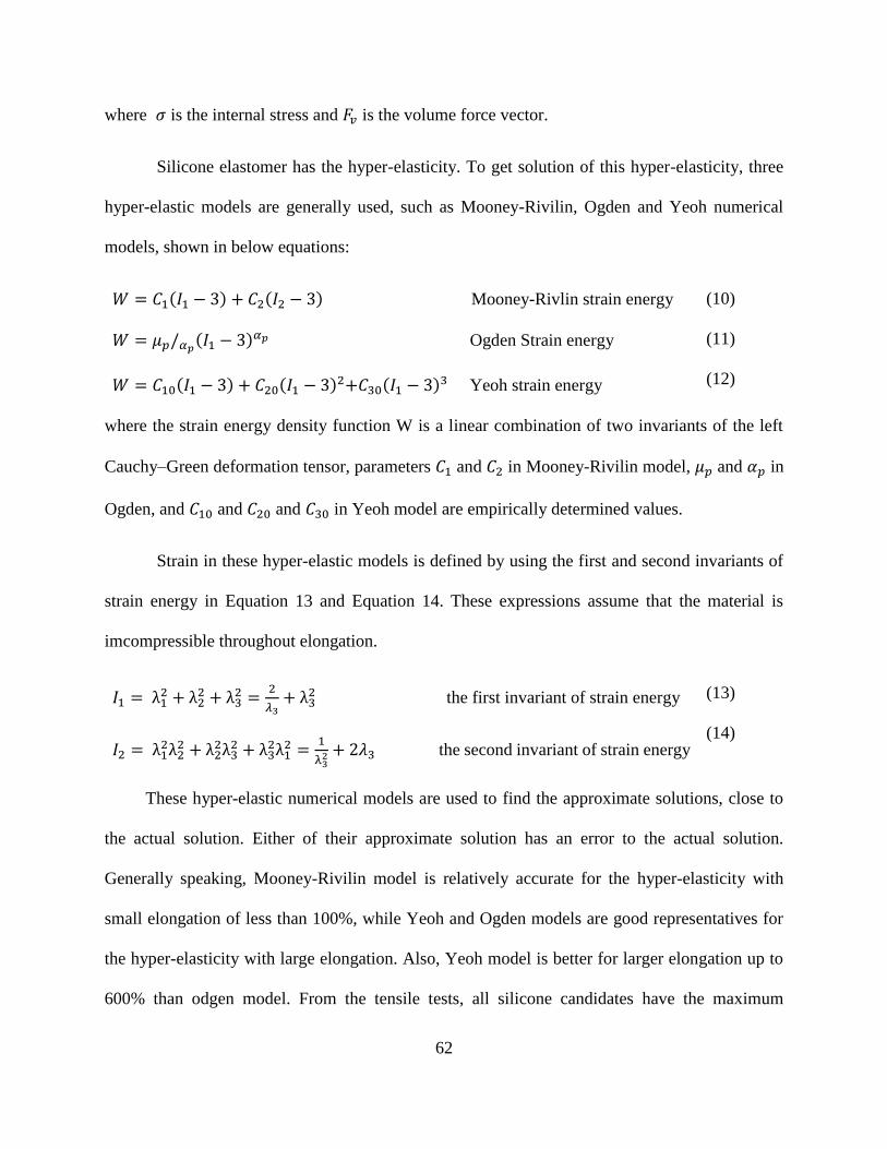
62
where 𝜎 is the internal stress and 𝐹𝑣 is the volume force vector.
Silicone elastomer has the hyper-elasticity. To get solution of this hyper-elasticity, three
hyper-elastic models are generally used, such as Mooney-Rivilin, Ogden and Yeoh numerical
models, shown in below equations:
𝑊 = 𝐶1(𝐼1 − 3) + 𝐶2(𝐼2 − 3) Mooney-Rivlin strain energy
𝑊 = 𝜇𝑝/𝛼𝑝(𝐼1 − 3)𝛼𝑝 Ogden Strain energy
𝑊 = 𝐶10(𝐼1 − 3) + 𝐶20(𝐼1 − 3)2+𝐶30(𝐼1 − 3)3 Yeoh strain energy
(10)
(11)
(12)
where the strain energy density function W is a linear combination of two invariants of the left
Cauchy–Green deformation tensor, parameters 𝐶1 and 𝐶2 in Mooney-Rivilin model, 𝜇𝑝 and 𝛼𝑝 in
Ogden, and 𝐶10 and 𝐶20 and 𝐶30 in Yeoh model are empirically determined values.
Strain in these hyper-elastic models is defined by using the first and second invariants of
strain energy in Equation 13 and Equation 14. These expressions assume that the material is
imcompressible throughout elongation.
𝐼1 = λ12 + λ2
2 + λ32 =
2
𝜆3+ λ3
2 the first invariant of strain energy
𝐼2 = λ12λ2
2 + λ22λ3
2 + λ32λ1
2 =1
λ32 + 2𝜆3 the second invariant of strain energy
(13)
(14)
These hyper-elastic numerical models are used to find the approximate solutions, close to
the actual solution. Either of their approximate solution has an error to the actual solution.
Generally speaking, Mooney-Rivilin model is relatively accurate for the hyper-elasticity with
small elongation of less than 100%, while Yeoh and Ogden models are good representatives for
the hyper-elasticity with large elongation. Also, Yeoh model is better for larger elongation up to
600% than odgen model. From the tensile tests, all silicone candidates have the maximum

63
elongation about 600%. Thus, Yeoh model is selected for silicone elastomers in this research.
Parameters in the Yeoh strain energy function was calculated from the measured silicone elasticity
curves by applying Curve Fitting Toolbox in MATLAB. Yeoh model parameters for the best
silicone candidate, LIM 6010, are listed in the Table 11 below.
Table 11. Yeoh hyperelastic material model parameters for LIM6010 silicone
C10 (MPa) C20 (MPa) C30 (MPa)
0.01459 -0.00014 1.49E-06
3.3.4.1.3 Boundary condition
After determining all physical principles in DEA simulation, the real boundary conditions
were also added to the circular and rectangular DEA models. Boundary condition is very essential
to get the solution from those governing equations of electrostatics and structural mechanics. For
example, two boundary conditions in the electrostatics are the electric potential on the surfaces of
electrodes and the zero charge for the rest of surfaces. For the structural mechanics, several
boundary conditions are applied, such as the fixed constraints for zero displacements at the rigid
frames of DEA, boundary load for applying Maxwell stress tensor and free constraint for free
actuation.
3.3.4.2 Validation of empirical and modeling results
After setting up the numerical model, it is necessary to validate this numerical model with
experimental results. Primarily, rectangular DEA model need to match up experimental setup, such
as silicone membrane of 70x44 mm2 area and 0.22 mm thickness and carbon grease film of 20
mm diameter and 1 mm thickness. However, in this numerical model, the pre-stretched silicone
film is difficult to build with non-stretched carbon grease film. Hence, this numerical model
applied the minimum width of 44 mm at the middle of the pre-stretched silicone film in the
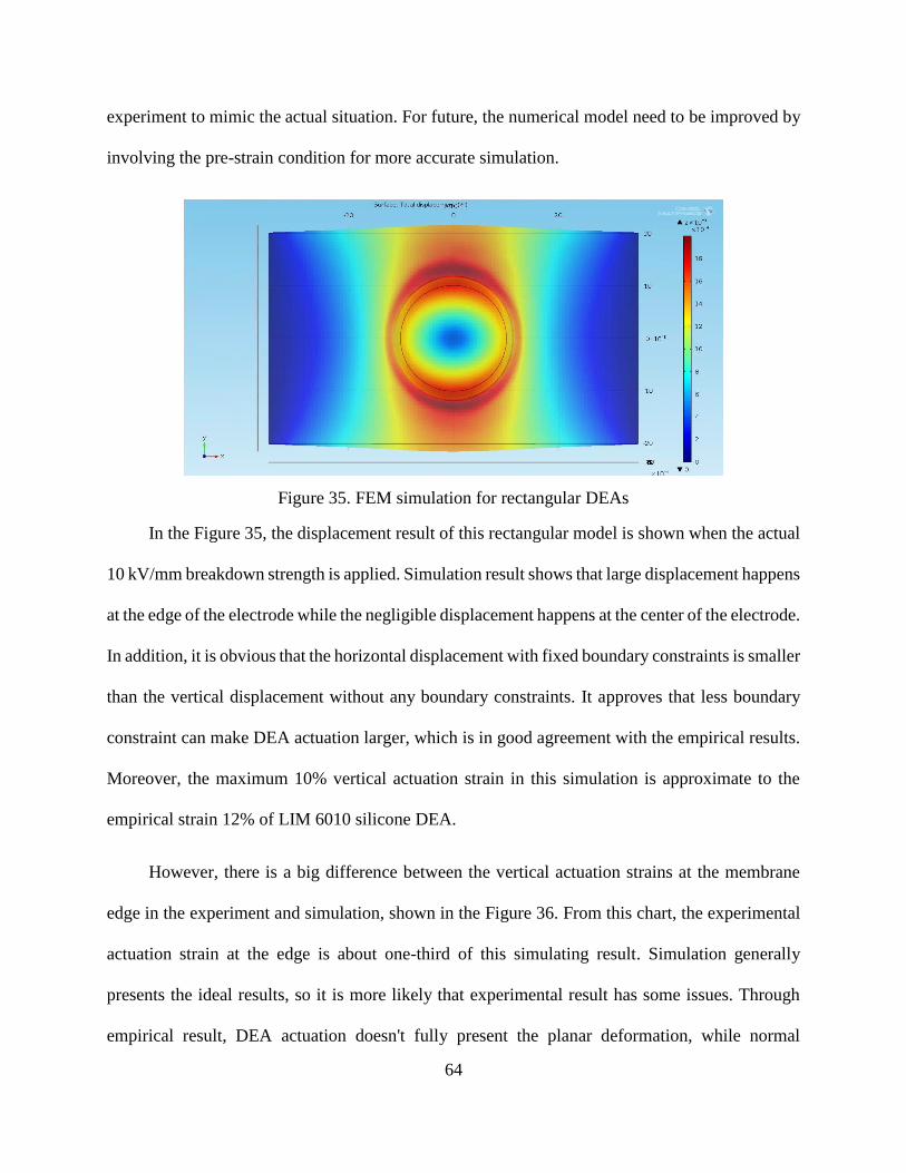
64
experiment to mimic the actual situation. For future, the numerical model need to be improved by
involving the pre-strain condition for more accurate simulation.
Figure 35. FEM simulation for rectangular DEAs
In the Figure 35, the displacement result of this rectangular model is shown when the actual
10 kV/mm breakdown strength is applied. Simulation result shows that large displacement happens
at the edge of the electrode while the negligible displacement happens at the center of the electrode.
In addition, it is obvious that the horizontal displacement with fixed boundary constraints is smaller
than the vertical displacement without any boundary constraints. It approves that less boundary
constraint can make DEA actuation larger, which is in good agreement with the empirical results.
Moreover, the maximum 10% vertical actuation strain in this simulation is approximate to the
empirical strain 12% of LIM 6010 silicone DEA.
However, there is a big difference between the vertical actuation strains at the membrane
edge in the experiment and simulation, shown in the Figure 36. From this chart, the experimental
actuation strain at the edge is about one-third of this simulating result. Simulation generally
presents the ideal results, so it is more likely that experimental result has some issues. Through
empirical result, DEA actuation doesn't fully present the planar deformation, while normal
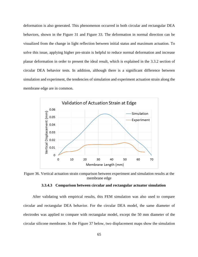
65
deformation is also generated. This phenomenon occurred in both circular and rectangular DEA
behaviors, shown in the Figure 31 and Figure 33. The deformation in normal direction can be
visualized from the change in light reflection between initial status and maximum actuation. To
solve this issue, applying higher pre-strain is helpful to reduce normal deformation and increase
planar deformation in order to present the ideal result, which is explained in the 3.3.2 section of
circular DEA behavior tests. In addition, although there is a significant difference between
simulation and experiment, the tendencies of simulation and experiment actuation strain along the
membrane edge are in common.
Figure 36. Vertical actuation strain comparison between experiment and simulation results at the
membrane edge
3.3.4.3 Comparison between circular and rectangular actuator simulation
After validating with empirical results, this FEM simulation was also used to compare
circular and rectangular DEA behavior. For the circular DEA model, the same diameter of
electrodes was applied to compare with rectangular model, except the 50 mm diameter of the
circular silicone membrane. In the Figure 37 below, two displacement maps show the simulation

66
results of circular and rectangular DEA models both at 10 kV/mm breakdown strength. It is
obvious that different configurations have different DEA actuation. For example, isotropic DEA
actuation happens to circular DEA configuration with isotropic boundary constraint, while
rectangular DEA configuration has relatively large actuation in the direction without any boundary
constraints. Thus, it indicates that boundary constraints in different DEA configurations have a
significant impact on DEA actuation. In addition, the largest displacement in rectangular DEA is
twice of that in circular DEAs. It indicates that rectangular DEA is capable of producing more
actuation strain.
Figure 37. FEM simulation results for circular and rectangular DEAs
3.3.5 Result discussion
In this section, the study of circular and rectangular DEA configurations was done though
experiments and simulations. Circular and rectangular DEAs were tested on HV test system about
their DEA actuation behavior, and actuation strains were measured through a validated image
processing. Maximum actuation strain of 5.9% in circular DEAs was found in KE-1283 silicone,
while 12.5% actuation strain was found in the vertical direction of LIM 6010 rectangular DEA.
67
These two best performance silicone candidates are employed in the later soft robotic development
based on circular or rectangular DEA.
In addition, rectangular and circular FEM models, including coupling physic phenomena,
hyperelastic material models and boundary constraints, was built to further understand the working
principles behind DEA actuation. This numerical model was validated with empirical results, and
showed a good agreement. More importantly, the hypothesis that less boundary constraint in
rectangular DEAs makes actuation large was validated by the empirical and modeling results. It is
new for understanding the effect of boundary constraint on DEA actuation.
3.4 Summary
In this chapter, I investigated the impact of pre-strain condition on material properties to find
the optimal pre-strain and the impact of DEA configurations on DEA actuation behaviors to select
the optimal configuration with the most actuation freedom for obtaining large DEA actuation.
Pre-strain condition was investigated with the silicone’s material properties, including
Young’s modulus, dielectric constant and dielectric breakdown strength. From the change of
Young’s modulus with strain, the general 40% to 200% applicable range of pre-strain condition is
determined to reduce about 40% Young’s modulus. Dielectric constant and breakdown strength
measurements up to 100% elongation show the positive impact of pre-strain condition to increase
these properties. Thus, the pre-strain in the applicable range can enhance DEA actuation by
decreasing Young’s modulus to produce large mechanical deformation, increasing dielectric
constant and breakdown strength to generate large Maxwell pressure. In addition, these
investigations also indicate that higher pre-strain in the applicable range can produce larges
silicone DEA actuation, and the optimal pre-strain in the applicable range should be the maximum
68
value, generally 200%. However, all silicone films with 10% film thickness variation in DEA
configuration were successfully pre-stretched by 40% in the experiments.
In addition, two different DEA configurations, circular and rectangular types, showed
different DEA actuation through experiments and simulations. two different DEA configurations,
circular and rectangular types, were investigated about their impacts on DEA actuation through
experiments and simulations. In experiments, rectangular silicone DEA has a 12.5% maximum
actuation strain, twice the maximum strain in circular silicone DEA. Two fold improvement
indicates that rectangular DEA configuration provides more actuation freedom than the circular
one. In FEM simulations, rectangular and circular DEA models validate the phenomenon in the
experiments. Hence, modeling and empirical results indicate that the rectangular DEA with less
boundary constraints can produce more actuation.
69
4 DIELECTRIC ELASTOMER ACTUATOR SMILEY FACE ROBOT
4.1 Introduction
In the previous chapters, a 3D printing process for DEAs has been developed, and the best
DEA behaviors among the selected silicone candidates has been identified. Next, developing a 4D
printed DEA robot is the ultimate goal of this research to demonstrate good customization of 3D
printing technology. 3D printing techniques provide more design freedom for DEA-based robots,
and also consume much lower cost of material and time than conventional subtractive
manufacturing methods. In this chapter, two 4D printed novel DEA smiley face robots are
demonstrated.
4.2 Quantitative Theory of Smiley Lip
The idea of this facial robotic system is that the expansion of pupils can be directly obtained
from circular electrodes which can expand isotropically, and the smiley lip can be demonstrated
from the differential deformation, which is the difference of deformation at different locations on
the lip when an electric field is applied. In order to demonstrate a smiley lip, a quantitative theory
of lip was designed, shown in the Figure 38 below. The dashed straight line is the lip at initial
status, and the solid curve line is the smiley lip. D is the differential deformation made by DEA
actuation, and L is the length of the lip. A visible smiley lip should have a large differential
deformation D with a short lip length L, and the smiley lip ratio of D over L is used to determine
a smiley lip. In the Figure 39, two easily recognized smile lips with different smiley lip ratios are
presented, which are one big smile and one normal smile. For example, a big smile should have
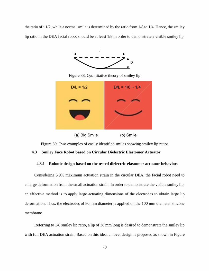
70
the ratio of ~1/2, while a normal smile is determined by the ratio from 1/8 to 1/4. Hence, the smiley
lip ratio in the DEA facial robot should be at least 1/8 in order to demonstrate a visible smiley lip.
Figure 38. Quantitative theory of smiley lip
Figure 39. Two examples of easily identified smiles showing smiley lip ratios
4.3 Smiley Face Robot based on Circular Dielectric Elastomer Actuator
4.3.1 Robotic design based on the tested dielectric elastomer actuator behaviors
Considering 5.9% maximum actuation strain in the circular DEA, the facial robot need to
enlarge deformation from the small actuation strain. In order to demonstrate the visible smiley lip,
an effective method is to apply large actuating dimensions of the electrodes to obtain large lip
deformation. Thus, the electrodes of 80 mm diameter is applied on the 100 mm diameter silicone
membrane.
Referring to 1/8 smiley lip ratio, a lip of 38 mm long is desired to demonstrate the smiley lip
with full DEA actuation strain. Based on this idea, a novel design is proposed as shown in Figure
L
D
(a) Big Smile (b) Smile
D/L = 1/2 D/L = 1/8 ~ 1/4
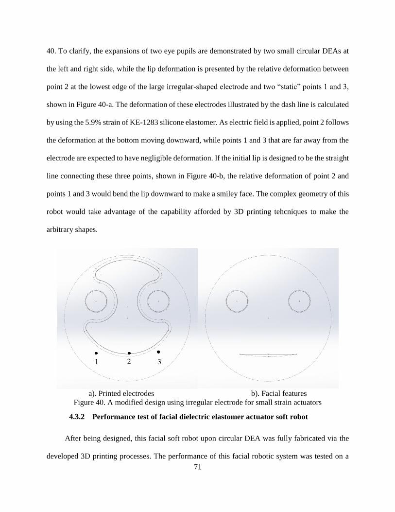
71
40. To clarify, the expansions of two eye pupils are demonstrated by two small circular DEAs at
the left and right side, while the lip deformation is presented by the relative deformation between
point 2 at the lowest edge of the large irregular-shaped electrode and two “static” points 1 and 3,
shown in Figure 40-a. The deformation of these electrodes illustrated by the dash line is calculated
by using the 5.9% strain of KE-1283 silicone elastomer. As electric field is applied, point 2 follows
the deformation at the bottom moving downward, while points 1 and 3 that are far away from the
electrode are expected to have negligible deformation. If the initial lip is designed to be the straight
line connecting these three points, shown in Figure 40-b, the relative deformation of point 2 and
points 1 and 3 would bend the lip downward to make a smiley face. The complex geometry of this
robot would take advantage of the capability afforded by 3D printing tehcniques to make the
arbitrary shapes.
a). Printed electrodes b). Facial features
Figure 40. A modified design using irregular electrode for small strain actuators
4.3.2 Performance test of facial dielectric elastomer actuator soft robot
After being designed, this facial soft robot upon circular DEA was fully fabricated via the
developed 3D printing processes. The performance of this facial robotic system was tested on a
1 2 3
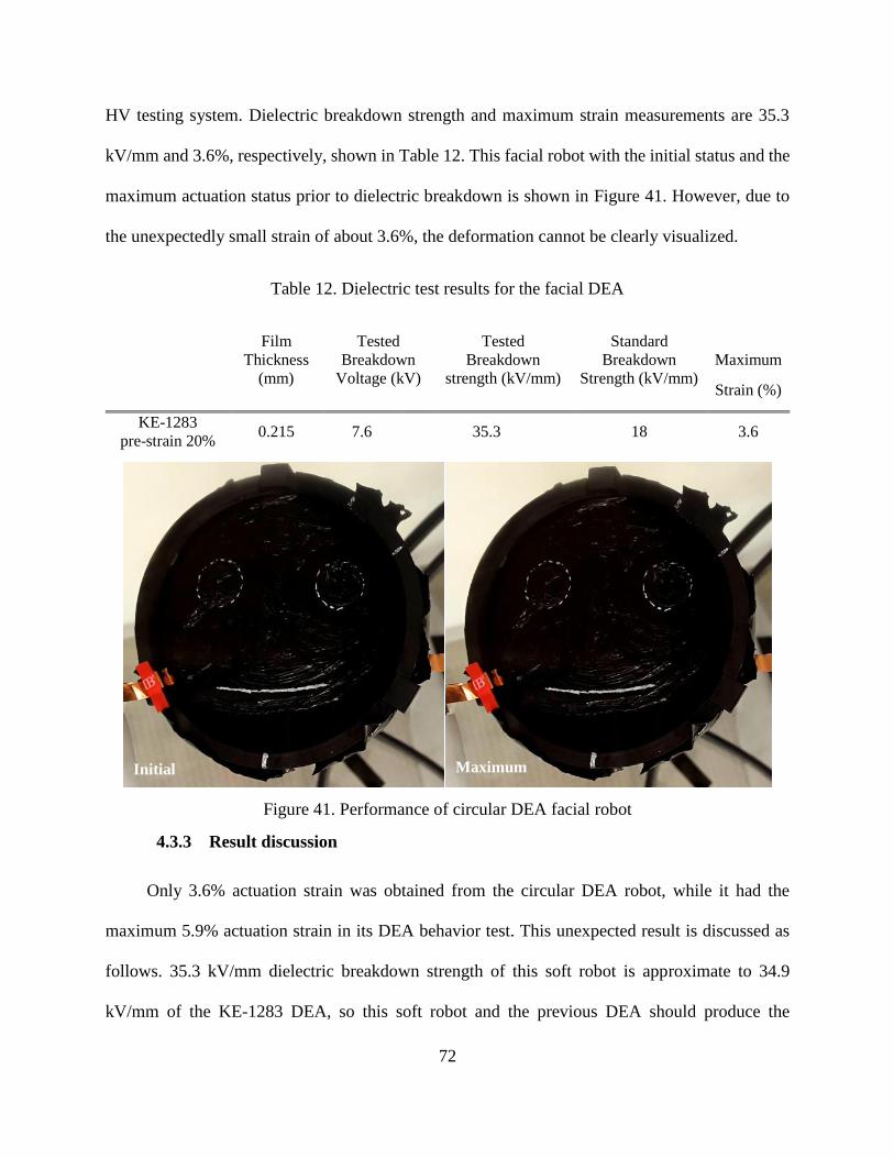
72
HV testing system. Dielectric breakdown strength and maximum strain measurements are 35.3
kV/mm and 3.6%, respectively, shown in Table 12. This facial robot with the initial status and the
maximum actuation status prior to dielectric breakdown is shown in Figure 41. However, due to
the unexpectedly small strain of about 3.6%, the deformation cannot be clearly visualized.
Table 12. Dielectric test results for the facial DEA
Film
Thickness
(mm)
Tested
Breakdown
Voltage (kV)
Tested
Breakdown
strength (kV/mm)
Standard
Breakdown
Strength (kV/mm)
Maximum
Strain (%)
KE-1283
pre-strain 20% 0.215 7.6 35.3 18 3.6
Figure 41. Performance of circular DEA facial robot
4.3.3 Result discussion
Only 3.6% actuation strain was obtained from the circular DEA robot, while it had the
maximum 5.9% actuation strain in its DEA behavior test. This unexpected result is discussed as
follows. 35.3 kV/mm dielectric breakdown strength of this soft robot is approximate to 34.9
kV/mm of the KE-1283 DEA, so this soft robot and the previous DEA should produce the
Initial Maximum

73
approximate Maxwell pressure. In addition, this soft robot and the previous DEA at the same 20%
pre-strain should have the same Young’s modulus of KE-1283 silicone. Hence, it is more likely
that the actuation strain of the large electrodes close to the circular frame is limited by the fixed
boundary constraints. This result need to be validated from more experimental and modeling data.
In addition, about 1.5 mm differential deformation of the smiley lip is also smaller than the
2.88 mm deformation from 3.6% actuation strain on 80 mm electrode. This phenomenon is
explained by a simulation of circular DEA, shown in the Figure 42. From this figure, a circular
DEA with a single electrode is shown to simplify the problem. A straight and solid line that locates
at the bottom edge of centric electrode represents the initial status of smiley lip. A curved and dash
line represents the ideal situation, which two ends of smiley lip have negligible deformations.
However, in fact, these deformations at the two ends are inevitable, shown as the curved and solid
line. Thus, the actual differential deformation is significantly smaller than the maximum
deformation from DEAs.
Figure 42. FEM simulation of circular DEA to present the unexpectedly small lip deformation
74
4.4 Smiley Face Robot based on Rectangular Dielectric Elastomer Actuator
Rectangular DEAs are more advantageous than circular DEAs to produce large deformation,
because rectangular configuration with less boundary constraint is capable of providing larger
actuation. A 12.5% maximum actuation strain was obtained in LIM6010 silicone rectangular DEA
in the previous DEA behavior test, which is about twice of the best circular DEA actuation. Thus,
rectangular DEAs are expected to present large lip deformation.
In addition, some phenomena in rectangular DEAs, such as edge effect and counter reaction,
were found through FEM simulations to increase the deformation at desired locations. To clarify
the edge effect in rectangular DEAs, a common DEA with circular electrodes at the center as the
control group was compared with another DEA with circular electrodes close to the unconstrained
membrane edge, as shown in the Figure 43. The common DEA has the symmetric actuation in x
or y direction shown in the Figure 43-a. 1.74 mm maximum displacement is shown at the top and
bottom edge of electrodes from a 20 mm diameter electrode.
For the DEA associated with the electrodes close to membrane edge, most of actuation occurs at
the bottom edge of the electrodes, shown in the Figure 43-b. The maximum displacement is 3.21
mm, which is about twice of the displacement in the DEA with the centric electrode. Hence, from
this comparison, it indicates that electrodes close to the membrane edge increase the displacement
at the bottom edge of electrodes. More importantly, this phenomenon can be manipulated to
produce larger deformation in the DEA soft robot.

75
(a)
(b)
Figure 43. FEM simulations for investigating the edge effect in rectangular DEA
Counter reaction phenomenon was also found via FEM simulation. To clarify, two sets of
compliant electrodes have a counter reaction to each other. When two sets of electrodes are close
to each other, the transverse stress induced by the electrostatic pressure in the normal direction
from each set of electrodes pushes another set of electrodes away. Thus, the counter reaction is
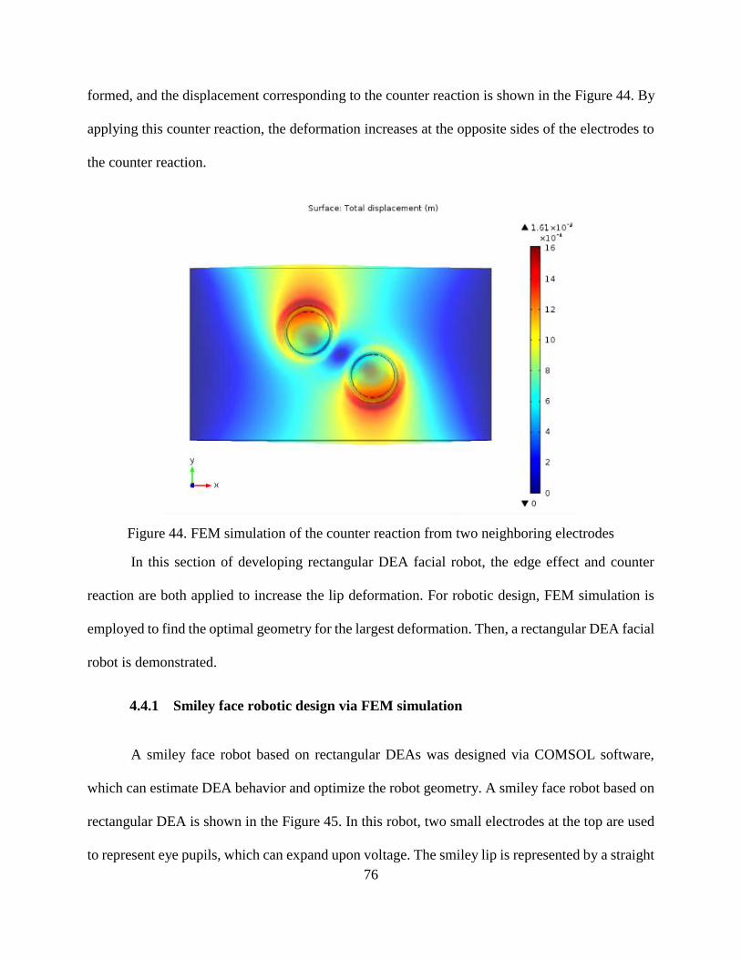
76
formed, and the displacement corresponding to the counter reaction is shown in the Figure 44. By
applying this counter reaction, the deformation increases at the opposite sides of the electrodes to
the counter reaction.
Figure 44. FEM simulation of the counter reaction from two neighboring electrodes
In this section of developing rectangular DEA facial robot, the edge effect and counter
reaction are both applied to increase the lip deformation. For robotic design, FEM simulation is
employed to find the optimal geometry for the largest deformation. Then, a rectangular DEA facial
robot is demonstrated.
4.4.1 Smiley face robotic design via FEM simulation
A smiley face robot based on rectangular DEAs was designed via COMSOL software,
which can estimate DEA behavior and optimize the robot geometry. A smiley face robot based on
rectangular DEA is shown in the Figure 45. In this robot, two small electrodes at the top are used
to represent eye pupils, which can expand upon voltage. The smiley lip is represented by a straight
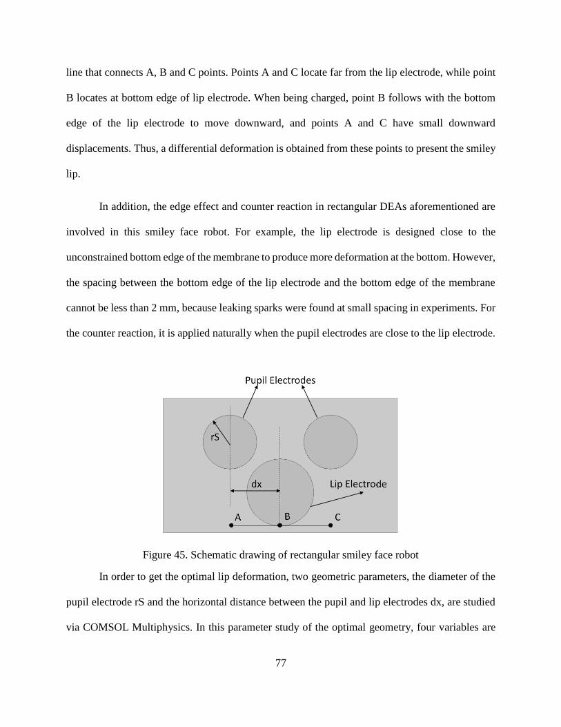
77
line that connects A, B and C points. Points A and C locate far from the lip electrode, while point
B locates at bottom edge of lip electrode. When being charged, point B follows with the bottom
edge of the lip electrode to move downward, and points A and C have small downward
displacements. Thus, a differential deformation is obtained from these points to present the smiley
lip.
In addition, the edge effect and counter reaction in rectangular DEAs aforementioned are
involved in this smiley face robot. For example, the lip electrode is designed close to the
unconstrained bottom edge of the membrane to produce more deformation at the bottom. However,
the spacing between the bottom edge of the lip electrode and the bottom edge of the membrane
cannot be less than 2 mm, because leaking sparks were found at small spacing in experiments. For
the counter reaction, it is applied naturally when the pupil electrodes are close to the lip electrode.
Figure 45. Schematic drawing of rectangular smiley face robot
In order to get the optimal lip deformation, two geometric parameters, the diameter of the
pupil electrode rS and the horizontal distance between the pupil and lip electrodes dx, are studied
via COMSOL Multiphysics. In this parameter study of the optimal geometry, four variables are

78
used for either of two parameters rS or dx. The smiley lip ratio for each geometry is calculated,
shown in the Figure 46. It shows that the largest smiley lip ratio of 0.075 is obtained in the optimal
geometry with 8 mm rS and 15 mm dx. Although the largest ratio is still smaller than the desired
ratio of 0.125 (1/8), at least the smiley lip of this optimal geometry is visible via COMSOL, shown
in the Figure 47.
Figure 46. Geometric parameter study of rectangular DEA robot
Figure 47. FEM simulation of the optimal result from this smiley face robot
2
6
0.070
0.072
0.074
0.076
1520
2530
rS (
mm
)
Smile
y Li
p R
atio
dx (mm)
Geometric Parameter Study
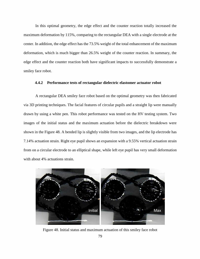
79
In this optimal geometry, the edge effect and the counter reaction totally increased the
maximum deformation by 115%, comparing to the rectangular DEA with a single electrode at the
center. In addition, the edge effect has the 73.5% weight of the total enhancement of the maximum
deformation, which is much bigger than 26.5% weight of the counter reaction. In summary, the
edge effect and the counter reaction both have significant impacts to successfully demonstrate a
smiley face robot.
4.4.2 Performance tests of rectangular dielectric elastomer actuator robot
A rectangular DEA smiley face robot based on the optimal geometry was then fabricated
via 3D printing techniques. The facial features of circular pupils and a straight lip were manually
drawn by using a white pen. This robot performance was tested on the HV testing system. Two
images of the initial status and the maximum actuation before the dielectric breakdown were
shown in the Figure 48. A bended lip is slightly visible from two images, and the lip electrode has
7.14% actuation strain. Right eye pupil shows an expansion with a 9.55% vertical actuation strain
from on a circular electrode to an elliptical shape, while left eye pupil has very small deformation
with about 4% actuations strain.
Figure 48. Initial status and maximum actuation of this smiley face robot
Initial Max
80
4.4.3 Result discussion
The performance of this smiley face robot was imperfect to match the simulation result,
because the actuation strains of three compliant electrodes were unequal and all smaller than the
maximum 12.5% DEA actuation strain. In fact, this robot failed after a leaking spark occurred at
the bottom edge of the right pupil electrode, so dielectric breakdown is the failure reason. The 28
kV/mm breakdown strength of this robot is much smaller than the 40 kV/mm breakdown strength
of the same silicone DEA with the 12.5% actuation strain.
The uneven thickness distribution with over 50 µm variation was found on the average 200
µm thick membrane of this robot. Specifically, the right side of the membrane is thinner than the
left side. The electric field can more easily break down the membrane at the thinner places. In
addition, the gradually decreasing actuation strains (9.55%, 7.14% and about 4%) of three
electrodes corresponds to the increasing silicone film thickness. It indicates that thinner places are
easier to produce larger DEA actuation, approaching to the maximum 12.5% DEA actuation strain
that is also approaching to the dielectric breakdown strength. Hence, the early dielectric breakdown
is induced by the uneven thickness of the membrane. The 50 µm thickness variation in silicone
film was the result of the standard 100 µm accuracy on Fab@Home printer. In order to fabricate a
good DEA soft robot, 3D printers with the finer accuracy are preferred to use.
4.5 Summary:
In this chapter, I reported fully 3D printed soft robotic faces using DEAs for the first time.
1/8 smiley lip ratio from the differential deformation of DEAs was determined to present a visible
smiley lip, and eye pupils were presented from circular shape DEAs. Two novel soft robotic faces
of using circular or rectangular DEAs were demonstrated upon application of voltage. 3D printing

81
techniques are approved to feasibly and easily fabricate the complex geometry in DEA robotic
design. COMSOL Multiphysics software is involved in the design of DEA face robot, including
the optimization and prediction of robotic performance.
82
5 CONCLUSION
This thesis is motivated to develop a digital fabrication method for DEA based soft robots
via 3D printing technologies. The objective is to fully 3D print DEA robot with large actuation.
The fabrication process was developed for DEAs via 3D printing techniques. Silicone films with
about 300 µm thickness and carbon grease films with good conductivity until 40% elongation was
3D printed.
In addition, in order to enlarge DEA actuation, the impact of pre-strain condition on silicone
material properties and the impact of DEA configurations on DEA actuation were investigated to
find the optimal pre-strain and select the optimal configuration with the most actuation freedom,
respectively. Specifically, pre-strain condition was found to enhance DEA actuation by reducing
Young’s modulus to produce large mechanical deformation, increasing dielectric constant and
breakdown strength to generate large Maxwell pressure. The investigation of DEA configuration
indicates that rectangular DEAs have less boundary constraints to produce larger DEA actuation
than circular DEAs, through experiments and simulations. The maximum 12.5% actuation strain
was obtained from 3D printed rectangular LIM6010 silicone DEA. 20 times enhancement of
actuation strain on 3D printed DEA was achieved in this thesis, compared to literature.
Furthermore, I demonstrated 4D printed smiley face DEA soft robots for the first time. The
geometric design of these smiley face robots employed the quantitative theory of smiley lip and
COMSOL multiphysics simulation.

83
6 FUTURE WORK
For the future development of 3D printed DEAs, a number of improvements are desired to
further achieve the characteristics of DEAs that outperform human muscle, including large
actuation strain and stress, high working efficiency and fast response time. In this thesis, in order
to obtain large actuation, we demonstrated a 12.5% actuation strain of 3D printed DEA, which is
20 times of existing 3D printed DEA in the literature. Nonetheless, in order to obtain the
comparable actuation strain to 80% through conventional manufacturing methods, the finer
resolution 3D printer is needed to fabricate thin silicone films with more even thickness
distribution for applying the optimal pre-strain of about 200%.
3D printing technologies are also capable of enhancing DEA actuation stress. To clarify,
multi-stacked DEAs that are designed for replicating actuation stress are recommended to be 3D
printed by taking the advantages of 3D printing technologies, such as ease of fabrication and more
design freedom.
To achieve high working efficiency in DEA based soft robot, geometric optimization is
necessary to reduce the burden of unnecessary materials and maximize DEA actuation. 3D printing
technologies are much easier to fabricate the optimized DEA based soft robot due to its ease of
customization.
DEAs typically have a few milli-seconds response time or less than 1 kHz actuation
frequency, due to its time-dependent viscoelastic material property. Even though its response time
is much faster than that of biological mechanism (100 milli-seconds in human muscle), DEAs have
difficulty responding to higher than 1 kHz electrical signal. Ultra-sonic motion is almost
impossible for DEA based soft robots. On the other hand, DEA can naturally filter over 1 kHz high

84
frequency noise, which enables some new applications of anti-vibration and noise-cancellation for
3D printed DEAs or 3D printed DEA based robots.
For the future development of 3D printed DEA based soft robots, there are many potential
applications, such as bio-mimetic robots and evolutionary designs. For example, biology offers
abundant mechanisms in life, which can take the advantages of DEA based soft robots, such as
large actuation strain, light weight, fast response and etc. Some bio-mimetic robots associated with
artificial muscle are earthworm robots [1, 2], hexapod inspired robots [3, 4], Gecko climbing robot
[5] and micro flying insect robot [6]. In order to develop DEA based bio-mimetic robots, there are
some suggested objectives, such as understanding the working mechanisms of robotic locomotion,
validating robotic performances with simulations, optimizing robotic geometry and configuration,
and building the control system for complex robotic functions.
In addition, as science and technology develops, some precise apparatuses, like optical and
MEMS devices, have huge desires for the evolutional designs and prototypes of soft robots. The
evolutional designs and prototypes of soft robots are easily affordable via 3D printing technologies
to enable smart mechanisms, short design time, and aesthetic design elements. For example, a
smart mechanism of binary actuation system can be achieved from 3D printed DEA based soft
robot. Binary actuation basically has two stable and discrete states, original status and actuation.
For DEAs, these two states could be represented by the initial length and the actuating length upon
the application of voltage. A binary actuation system can program many simple binary DEAs to
very sophisticated functions, like binary code in computer. To explain, a soft robot with three
binary DEAs has eight (23) degrees of freedom. Therefore, future researchers may develop a binary
actuation system associated with large actuation DEAs to achieve sophisticated functions.
85
References
[1] A. Menciassi, S. Gorini, G. Pernorio, L. Weiting, F. Valvo and P. Dario, "Design, fabrication
and performances of a biomimetic robotic earthworm," in Robotics and Biomimetics, 2004.
ROBIO 2004. IEEE International Conference On, 2004, pp. 274-278.
[2] B. A. Trimmer, A. E. Takesian, B. M. Sweet, C. B. Rogers, D. C. Hake and D. J. Rogers,
"Caterpillar locomotion: A new model for soft-bodied climbing and burrowing robots," in 7th
International Symposium on Technology and the Mine Problem, 2006, pp. 1-10.
[3] J. G. Cham, S. A. Bailey, J. E. Clark, R. J. Full and M. R. Cutkosky, "Fast and robust:
Hexapedal robots via shape deposition manufacturing," The International Journal of Robotics
Research, vol. 21, pp. 869-882, 2002.
[4] A. J. McClung, M. R. Cutkosky and J. G. Cham, "Rapid maneuvering of a biologically
inspired hexapedal robot," in ASME 2004 International Mechanical Engineering Congress and
Exposition, 2004, pp. 1195-1202.
[5] S. Kim, M. Spenko, S. Trujillo, B. Heyneman, V. Mattoli and M. R. Cutkosky, "Whole body
adhesion: Hierarchical, directional and distributed control of adhesive forces for a climbing
robot," in Robotics and Automation, 2007 IEEE International Conference On, 2007, pp. 1268-
1273.
[6] R. Wood, S. Avadhanula, R. Sahai, E. Steltz and R. Fearing, "Microrobot design using fiber
reinforced composites," Journal of Mechanical Design, vol. 130, pp. 052304, 2008.
[7] K. Cho, J. Koh, S. Kim, W. Chu, Y. Hong and S. Ahn, "Review of manufacturing processes
for soft biomimetic robots," International Journal of Precision Engineering and Manufacturing,
vol. 10, pp. 171-181, 2009.
[8] R. Merz, F. Prinz, K. Ramaswami, M. Terk and L. Weiss, Shape Deposition Manufacturing.
Engineering Design Research Center, Carnegie Mellon Univ., 1994.
[9] F. Carpi, D. De Rossi, R. Kornbluh, R. E. Pelrine and P. Sommer-Larsen, Dielectric
Elastomers as Electromechanical Transducers: Fundamentals, Materials, Devices, Models and
Applications of an Emerging Electroactive Polymer Technology. Elsevier, 2011.
[10] A. O’Halloran, F. O’Malley and P. McHugh, "A review on dielectric elastomer actuators,
technology, applications, and challenges," J. Appl. Phys., vol. 104, pp. 071101, 2008.
[11] C. Keplinger, J. Y. Sun, C. C. Foo, P. Rothemund, G. M. Whitesides and Z. Suo,
"Stretchable, transparent, ionic conductors," Science, vol. 341, pp. 984-987, Aug 30, 2013.
[12] S. J. A. Koh, X. Zhao and Z. Suo, "Maximal energy that can be converted by a dielectric
elastomer generator," Appl. Phys. Lett., vol. 94, pp. 262902, 2009.
86
[13] J. Madden, N. Vandesteeg, P. Anquetil, P. Madden, A. Takshi, R. Pytel, S. Lafontaine, P.
Wieringa and I. Hunter, "Artificial muscle technology: Physical principles and naval prospects,"
IEEE J. Ocean. Eng., vol. 29, pp. 706-728, JUL, 2004.
[14] Kornbluh, Roy D., Ron Pelrine, Qibing Pei, Seajin Oh, and Jose Joseph., "Ultrahigh strain
response of field-actuated elastomeric polymers," International Society for Optics and
Photonics, pp. 51-64, SPIE's 7th Annual International Symposium on Smart Structures and
Materials, 2000.
[15] R. Pelrine, R. Kornbluh, J. Joseph, R. Heydt, Q. Pei and S. Chiba, "High-field deformation
of elastomeric dielectrics for actuators," Materials Science & Engineering C-Biomimetic and
Supramolecular Systems, vol. 11, pp. 89-100, NOV, 2000.
[16] M. Wissler and E. Mazza, "Mechanical behavior of an acrylic elastomer used in dielectric
elastomer actuators," Sensors and Actuators A: Physical, vol. 134, pp. 494-504, 2007.
[17] Y. Liu, L. Liu, Z. Zhang and J. Leng, "Dielectric elastomer film actuators: characterization,
experiment and analysis," Smart Mater. Struct., vol. 18, pp. 095024, 2009.
[18] G. Yang, G. Yao, W. Ren, G. Akhras, J. P. Szabo and B. K. Mukherjee, "The strain
response of silicone dielectric elastomer actuators," in Smart Structures and Materials, 2005, pp.
134-143.
[19] S. Akbari, S. Rosset and H. R. Shea, "More than 10 fold increase in the actuation strain of
silicone dielectric elastomer actuators by applying prestrain," Electroactive Polymer Actuators
and Devices (Eapad) 2013, vol. 8687, pp. 86871P, 2013.
[20] S. Michel, X. Q. Zhang, M. Wissler, C. Löwe and G. Kovacs, "A comparison between
silicone and acrylic elastomers as dielectric materials in electroactive polymer actuators," Polym.
Int., vol. 59, pp. 391-399, 2010.
[21] H. Winter, J. Lambrecht and R. Bärsch, "On the measurement of the dielectric strength of
silicone elastomers," in Universities Power Engineering Conference (UPEC), 2010 45th
International, 2010, pp. 1-5.
[22] D. Gatti, H. Haus, M. Matysek, B. Frohnapfel, C. Tropea and H. F. Schlaak, "The dielectric
breakdown limit of silicone dielectric elastomer actuators," Appl. Phys. Lett., vol. 104, pp.
052905, 2014.
[23] G. Finis and A. Claudi, "On the dielectric breakdown behavior of silicone gel under various
stress conditions," Dielectrics and Electrical Insulation, IEEE Transactions On, vol. 14, pp. 487-
494, 2007.
[24] F. Carpi and D. D. Rossi, "Improvement of electromechanical actuating performances of a
silicone dielectric elastomer by dispersion of titanium dioxide powder," Dielectrics and
Electrical Insulation, IEEE Transactions On, vol. 12, pp. 835-843, 2005.

87
[25] Z. Zhang, L. Liu, J. Fan, K. Yu, Y. Liu, L. Shi and J. Leng, "New silicone dielectric
elastomers with a high dielectric constant," in The 15th International Symposium on: Smart
Structures and Materials & Nondestructive Evaluation and Health Monitoring, 2008, pp.
692610-692610-8.
[26] I. Park, K. J. Kim, J. Nam, J. Lee and W. Yim, "Mechanical, dielectric, and magnetic
properties of the silicone elastomer with multi-walled carbon a nanotubes as a nanofiller,"
Polym. Eng. Sci., vol. 47, pp. 1396-1405, SEP, 2007.
[27] F. Galantini, F. Carpi and G. Gallone, "Effects of plasticization of a soft silicone for
dielectric elastomer actuation," Smart Mater. Struct., vol. 22, pp. 104020, 2013.
[28] F. B. Madsen, L. Yu, A. E. Daugaard, S. Hvilsted and A. L. Skov, "Silicone elastomers with
high dielectric permittivity and high dielectric breakdown strength based on dipolar
copolymers," Polymer, vol. 55, pp. 6212-6219, 2014.
[29] C. Racles, M. Cazacu, B. Fischer and D. M. Opris, "Synthesis and characterization of
silicones containing cyanopropyl groups and their use in dielectric elastomer actuators," Smart
Mater. Struct., vol. 22, pp. 104004, 2013.
[30] P. Lotz, M. Matysek and H. F. Schlaak, "Fabrication and Application of Miniaturized
Dielectric Elastomer Stack Actuators," Ieee-Asme Transactions on Mechatronics, vol. 16, pp.
58-66, FEB, 2011.
[31] O. A. Araromi, A. T. Conn, C. S. Ling, J. M. Rossiter, R. Vaidyanathan and S. C. Burgess,
"Spray deposited multilayered dielectric elastomer actuators," Sensors and Actuators A-Physical,
vol. 167, pp. 459-467, JUN, 2011.
[32] D. Raviv, W. Zhao, C. McKnelly, A. Papadopoulou, A. Kadambi, B. Shi, S. Hirsch, D.
Dikovsky, M. Zyracki and C. Olguin, "Active Printed Materials for Complex Self-Evolving
Deformations," Scientific Reports, vol. 4, 2014.
[33] Q. Ge, C. K. Dunn, H. J. Qi and M. L. Dunn, "Active origami by 4D printing," Smart
Mater. Struct., vol. 23, pp. 094007, 2014.
[34] Q. Ge, K. K. Westbrook, P. T. Mather, M. L. Dunn and H. J. Qi, "Thermomechanical
behavior of a two-way shape memory composite actuator," Smart Mater. Struct., vol. 22, pp.
055009, 2013.
[35] E. Malone and H. Lipson, "Freeform fabrication of ionomeric polymer-metal composite
actuators," Rapid Prototyping Journal, vol. 12, pp. 244-253, 2006.
[36] J. Rossiter, P. Walters and B. Stoimenov, "Printing 3D dielectric elastomer actuators for soft
robotics," in SPIE Smart Structures and Materials Nondestructive Evaluation and Health
Monitoring, 2009, pp. 72870H-72870H-10.

88
[37] J. Risner, Investigation of Dielectric Elastomer Actuation for Printable Mechatronics.
ProQuest, 2008.
[38] B. Li, H. Chen, J. Qiang, S. Hu, Z. Zhu and Y. Wang, "Effect of mechanical pre-stretch on
the stabilization of dielectric elastomer actuation," Journal of Physics D-Applied Physics, vol.
44, pp. 155301, APR 20, 2011.
[39] S. Rosset, M. Niklaus, P. Dubois, M. Dadras and H. R. Shea, "Mechanical properties of
electroactive polymer microactuators with ion-implanted electrodes," in The 14th International
Symposium on: Smart Structures and Materials & Nondestructive Evaluation and Health
Monitoring, 2007, pp. 652410-652410-11.
[40] R. Pelrine, R. Kornbluh, J. Joseph, R. Heydt, Q. Pei and S. Chiba, "High-field deformation
of elastomeric dielectrics for actuators," Materials Science and Engineering: C, vol. 11, pp. 89-
100, 2000.
[41] S. Bergbreiter and K. S. Pister, "Elastomer-based micromechanical energy storage system,"
in ASME 2006 International Mechanical Engineering Congress and Exposition, 2006, pp. 539-
545.
Recommended