Over
view
XW S
erie
s E-
Stop
sIn
terl
ock
Switc
hes
Enab
ling
Switc
hes
Safe
ty C
ontro
l Rel
ays
Ligh
t Cur
tain
sAS
-Inte
rface
Saf
ety
at W
ork
ø22 HW Key Locking Safety Switches
364 www.IDEC.com 1705151128
ø22 HW Key Switch
Key features:• Key Selector Switches with Direct Opening Action Mechanism • High-security Pin Tumbler Key• The NC contact is opened by direct opening action mechanism . Mode selection enables easy
construction of safety systems.• The single key enables the hostage control of combining HW series key selector switch (pin tum-
bler type) and HS5E-K interlock key switch. High-security pin tumbler key is used. Sixteen types of key numbers are available.
• Selection of 2-position and 3-position, maintained, spring-return types and key retained variety is available.
• Degree of Protection: IP65 (IEC60529)
Applicable Standards Mark File No. or Organization
UL508 UL ListingFile No. E68961
CSA C22.2 No.14 CSA166730 (LR92374)
EN60947-5-1TÜV Rheinland R50054316
Self-declarationLow Voltage Directive of Europe
Two-position Key Switch (90°)
Standard Logic Inverse Logic
Contact Block Mounting Position
Contact Code
Contact Block Logic Table Maintained1 2
Logic Table Maintained12Mounting
Position Contact 1 2 1 2
1NO(10)
NO HW1K-2PA10
HW1K-2JPA10
– Dummy Block Dummy Block
1NC(01)
NC HW1K-2PA01
HW1K-2JPA01
– Dummy Block Dummy Block
2NO(20)
NO HW1K-2PA20
HW1K-2JPA20
NO
2NC(02)
NC HW1K-2PA02
HW1K-2JPA02
NC
1NO-1NC(11)
NO HW1K-2PA11
HW1K-2JPA11
NC
2NO-2NC(22)
NO
HW1K-2PA22
HW1K-2JPA22 NC
NO
NC
For contact block mounting position, see the figure to the right of the table.Each key selector switch is supplied with two keys. Key number 500 is supplied as the default key in table above (500 not added to part number).To order additional key types, specify key number at end of part number (special order).
Example: HS5E-KVA003-2A501 | 501 to 515Note: The key number is engraved on the cylinder.

365800-262-IDEC (4332) • USA & Canada
ø22 HWKey Locking Safety SwitchesOverview
XW Series E-Stops
Interlock Switches
Enabling Switches
Safety Control RelaysLight Curtains
AS-Interface Safety at Work
1705151128
Three-position Key Switch (45°)
Contact Code
Contact Block Logic TableCam Code
Maintained0
1 2
Contact Block Mounting Position
No. Contact 1 0 2
2NC(02)
NC– HW1K-3PA02
NC
2N0-2NC(22N1)
NO
– HW1K-3PA22N1 NO
NC
NC
2NO(02)
NO – HW1K-3PA20
NO
2NO-1NC(21N1)
NO
J HW1K-3JPA21N1 NO
NC
– Dummy Block
2NO-2NC(22N9)
NC
S HW1K-3SPA22N9 NC
NO
NO
4NC(04)
NC
S HW1K-3SPA04 NC
NC
NC
On the contact arrangement marked with in the table above, the rated current (load switching current) is reduced to a half of the rated current of the contact block. The rated insulation voltage and the rated thermal current remain unchanged.
For models with , contacts may overlap when the operator position is changed.For contact block mounting position, see the figure on the right.Each key selector switch is supplied with two keys.15 types of key numbers are available in addition to standard (500) key.Key number 500 is supplied as the default key in table above (500 not added to part number).To order additional key types, specify key number at end of part number (special order).
Example: HS5E-KVA003-2A501 | 501 to 515Note: The key number is engraved on the cylinder.
Dimensions (mm)
37.4
Mounting Panel Thickness: 0.8 to 6
26.5
49.4 (1-2 blocks)
0.5
13 29.4
25
ø29.4
41.4
Rubber Gasket
M3.5 Terminal Screw
Locking RingSafety Lever Lock LOCK
69.4 (3-4 blocks)
1 ContactBlock
2 ContactBlocks
4 ContactBlocks
Anti-rotation Ring and Panel cut-out Align the TOP marking on the operator and the TOP mark on the anti-rotation ring with the recess in the mounting panel.
Projection ( Mark)
HW Series Operator(Example)
Anti-rotation Ring
LockingRing
MountingPanel
Panel Thickness 1.2 to 4.5 mm
Gasket(0.5t)
Panel-cut(Complies with IEC 60947-5-1)
+0.40
0+0.2
0+
0.4
ø22.3
R0.8 max.
3.2
24.1

Over
view
XW S
erie
s E-
Stop
sIn
terl
ock
Switc
hes
Enab
ling
Switc
hes
Safe
ty C
ontro
l Rel
ays
Ligh
t Cur
tain
sAS
-Inte
rface
Saf
ety
at W
ork
ø22 HW Key Locking Safety Switches
366 www.IDEC.com 1705151128
Replacement PartsItem Material Part No. Remarks
Contact Block
1NO contact HW-G10 Housing color: bluePush rod: green
1NC contact HW-G01 Housing color: purplePush rod: red
Dummy Block
Nylon TW-DB Used when using contact blocks in odd numbers.
Spare Key
Metal (nickel-plated brass)
LW9Z-SK-500 Standard key number
LW9Z-SK- Key number 501 to 515
Locking Ring
Polyamide HW9Z-LN Black
Safety Lever Lock
Polyacetal HW9Z-LSYellowOne safety lever lock is supplied as standard.
Gasket
Polyacetal HW9Z-WM Black
Accessories
Item Material Part No. Dimensions
Locking Ring Wrench
Metal (brass)Weight: approx. 150g MW9Z-T1
Used to tighten the locking ring when installing the HW switch onto a panel.Tighten the locking ring to a torque of 2.0 N·m.
110 ø28
Contact Block Removal Tool
Metal(copper-zinc plating) / Nitrile Rubber
TW-KC1
Used to remove the contact block and the transformer, and also to install or remove the pilot light lens. Also used to adjust the panel thickness (1, 1.6, 2, 2.3, 3.2, and 5 mm).
ø1923
39
130 ø1923
39
130
Anti-rotation Ring
Ring: NylonGasket: Nitrile Rubber HW9Z-RL
Used to prevent the operator from turning.TOP
ø22ø29
1.5
367800-262-IDEC (4332) • USA & Canada
ø22 HWKey Locking Safety SwitchesOverview
XW Series E-Stops
Interlock Switches
Enabling Switches
Safety Control RelaysLight Curtains
AS-Interface Safety at Work
1705151128
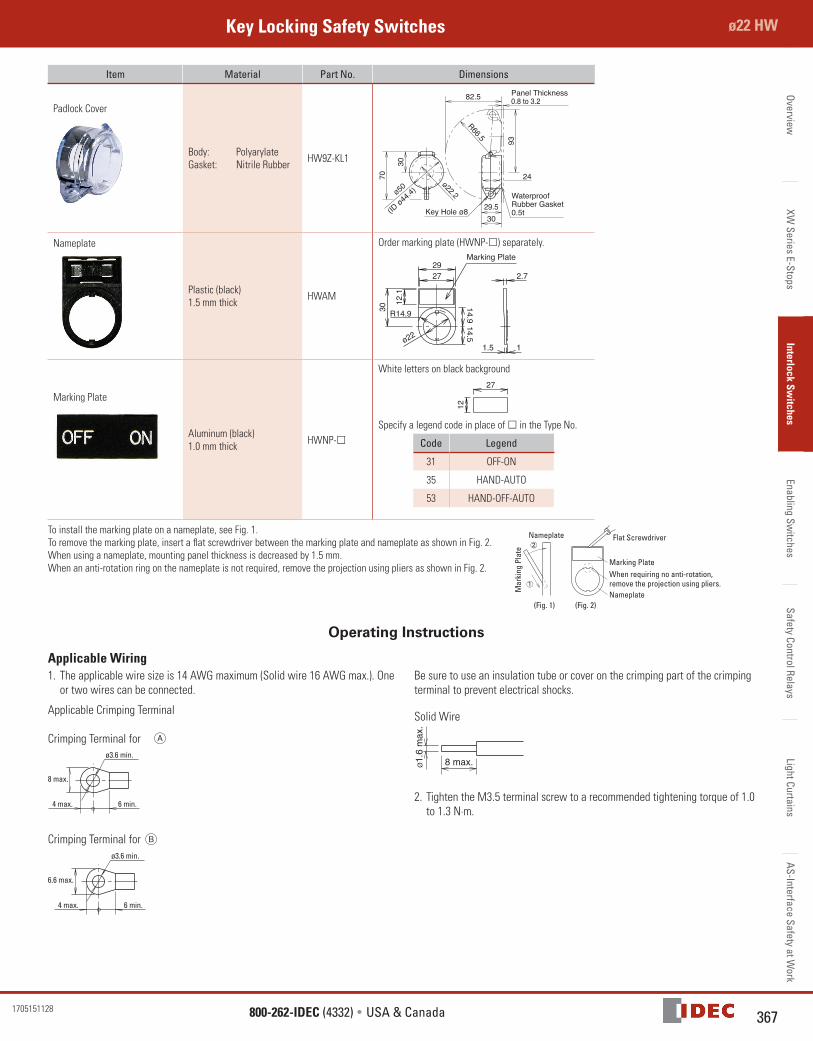
Item Material Part No. Dimensions
Padlock Cover
Body: PolyarylateGasket: Nitrile Rubber HW9Z-KL1
Key Hole ø8
30
70
ø50
93
29.530
R66.5
82.5
ø22.2
24
Waterproof Rubber Gasket0.5t
Panel Thickness0.8 to 3.2
(ID ø44
.4)
Nameplate
Plastic (black)1.5 mm thick HWAM
Order marking plate (HWNP-) separately.Marking Plate
30
12.1
14.9
27
14.511.5
2.729
ø22
R14.9
Marking Plate
Aluminum (black)1.0 mm thick HWNP-
White letters on black background27
12
Specify a legend code in place of in the Type No.
Code Legend
31 OFF-ON
35 HAND-AUTO
53 HAND-OFF-AUTO
To install the marking plate on a nameplate, see Fig. 1.To remove the marking plate, insert a flat screwdriver between the marking plate and nameplate as shown in Fig. 2.When using a nameplate, mounting panel thickness is decreased by 1.5 mm.When an anti-rotation ring on the nameplate is not required, remove the projection using pliers as shown in Fig. 2.
Nameplate
(Fig. 1)
When requiring no anti-rotation,remove the projection using pliers.Nameplate
Marking Plate
Flat Screwdriver
(Fig. 2)
Mar
king
Pla
te
Operating Instructions
Applicable Wiring1. The applicable wire size is 14 AWG maximum (Solid wire 16 AWG max.). One
or two wires can be connected.
Applicable Crimping Terminal
Crimping Terminal for ø3.6 min.
8 max.
4 max. 6 min.
Crimping Terminal for ø3.6 min.
6.6 max.
4 max. 6 min.
Be sure to use an insulation tube or cover on the crimping part of the crimping terminal to prevent electrical shocks.
Solid Wire
8 max.Ø1.
6 m
ax.
2. Tighten the M3.5 terminal screw to a recommended tightening torque of 1.0 to 1.3 N·m.
Recommended