Remote Controller (Wireless Type) O H 0 8 -1
86 C o n tro l S y s te m s
2 .5 B RC4 C6 5 / B RC4 C6 6 (for F X M Q -P )
2 .5 .1 F ea tu res
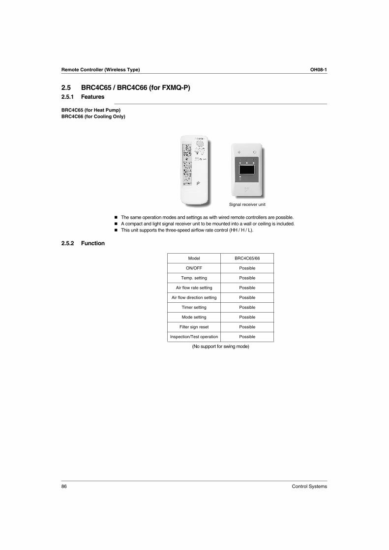
B RC4 C6 5 (for H ea t P u mp)
B RC4 C6 6 (for Cooling O nly)
T h e s a m e o p e ra tio n m o d e s a n d s e ttin g s a s w ith w ire d re m o te c o n tro lle rs a re p o s s ib le .
A c o m p a c t a n d lig h t s ig n a l re c e iv e r u n it to b e m o u n te d in to a w a ll o r c e ilin g is in c lu d e d .
T h is u n it s u p p o rts th e th re e -s p e e d a irflo w ra te c o n tro l (H H / H / L ).
2 .5 .2 F u nc tion
S ig n a l re c e iv e r u n it
M o d e l B R C 4 C 65 /66
O N /O F F P o s s ib le
T e m p . s e ttin g P o s s ib le
A ir flo w ra te s e ttin g P o s s ib le
A ir flo w d ire c tio n s e ttin g P o s s ib le
T im e r s e ttin g P o s s ib le
M o d e s e ttin g P o s s ib le
F ilte r s ig n re s e t P o s s ib le
In s p e c tio n /T e s t o p e ra tio n P o s s ib le
(N o s u p p o rt fo r s w in g m o d e )

OH08-1 Remote Controller (Wireless Type)
Control Systems 87
2
2.5.3 D imensions
• RE CE IV E R D E TAIL
(Ceiling Opening)
TRANSMITTING PART
• RE MOTE CONTROLLE R D IME NSIONS
(Ceili
ng O
penin
g)
• RE MOTE CONTROLLE R HOLD E R INSTALLATION PROCE D U RE < INSTALLATION TO W ALL SU RFACE >
Switch box
(Field Supplied parts)
• Service space for ceiling installation(S
ervi
ce s
pace
)
D o not install more than 3 receivers in the vicinity ofone another.W ith 4 or more units, there is always the possibilityof malfunction.
NOTE
mor
e th
an 9
0
0 .57 0
1 7 .5
157
106
72
49
62
83.5
LIQ U ID CRY STALRE MOTE CONTROLLE R(W IRE LE SS)
RE MOTE CONTROLLE RHOLD E R
120
3 51 8
2 -5 × 9 Slot
P1 P2
3 D 0 0 7 89 8B
2.5
BR
C4C
65 / B
RC
4C
66

Remote Controller (Wireless Type) OH08-1
88 Control Systems
2.5.4 Operation Manual
N ames and Functions of th e Operating S ection
1-1
1-2
7
9
12
10
11
13
14
15
8
1
3
4
5
2
6
DOWN
FAN
UP
ON OFF
MH L
C
hr.
hr.
TESTMODE
TIMER
RESERVE CANCEL
DOWN
UP
TEST
FAN
TIMETEMP
ON OFF
MH L
C
hr.
hr.
TEST
1
1-3 2
COOL /HE A T CHA N G E OV E R
RE MOTE CON TROL S WITCH
23
22
18
19
21
20
16
17

OH08-1 Remote Controller (Wireless Type)
Control Systems 89
2
See Fig. 1, 2
1DISPLAY “ ” (SIGNAL TRANSMISSION)
This lights up when a signal is being transmitted.
2
DISPLAY “ ” “ ” “ ” “ ” “ ” (OPERATION MODE)
This display shows the current OPERATION MODE. For straight cooling type, “ ” (Auto) and “ ”
(Heating) are not installed.
3DISPLAY “ ” (SET TEMPERATU RE)
This display shows the set temperature.
4DISPLAY “ ” (PROGRAMMED TIME)
This display shows PROGRAMMED TIME of the system start or stop.
5DISPLAY “ ” “ ” “ ” (FAN SPEED)
The display shows the set fan speed.
6DISPLAY “ ” (INSPECTION/ TEST OPERATION)
When the INSPECTION/TEST OPERATION BUTTON is pressed, the display shows the system mode is in.
7ON/OFF BU TTON
Press the button and the system will start. Press the button again and the system will stop.
8FAN SPEED CONTROL BU TTON
Press this button to select the fan speed, HH or H or L, of your choice.
9
TEMPERATU RE SETTING BU TTON
Use this button for SETTING TEMPERATURE (Operates with the front cover of the remote controller
closed.)
10
PROGRAMMING TIMER BU TTON
Use this button for programming “START and/or STOP” time. (Operates with the front cover of the remote
controller opened.)
11TIMER MODE START/STOP BU TTON
Refer to page 97.
12TIMER RESERVE/CANCEL BU TTON
Refer to page 97.
13OPERATION MODE SELECTOR BU TTON
Press this button to select OPERATION MODE.
14FILTER SIGN RESET BU TTON
Refer to the section of MAINTENANCE in the operation manual attached to the indoor unit.
15INSPECTION/TEST OPERATION BU TTON
This button is used only by q ualified service persons for maintenance purposes.
16EMERGENCY OPERATION SWITCH
This switch is readily used if the remote controller does not work .
17RECEIVER
This receives the signals from the remote controller.
18OPERATING INDICATOR LAMP (Red)
This lamp stays lit while the air conditioner runs. It flashes when the unit is in trouble.
19TIMER INDICATOR LAMP (Green)
This lamp stays lit while the timer is set.
MH L
C
hr. hr.
TEST
2.5
BR
C4C
65 / B
RC
4C
66

Remote Controller (Wireless Type) OH08-1
90 Control Systems
NOTE
For the sake of explanation, all indications are shown on the display in Figure 1 contrary to actual
running situations.
Fig. 1-2 shows the remote controller with the front cover opened.
Fig. 1-3 shows this remote controller can be used in conjunction with the one provided with the VRV
system.
If the air filter cleaning time indicator lamp lights up, clean the air filter as explained in the operation
manual provided with the indoor unit.
After cleaning and reinstalling the air filter, press the filter sign reset button on the remote controller.
The air filter cleaning time indicator lamp on the receiver will go out.
20AIR FILTER CLEANING TIME INDICATOR LAMP (Red)
Lights up when it is time to clean the air filter.
21DEFROST LAMP (Orange)
Lights up when the defrosting operation has started. (For straight cooling type this lamp does not turn on.)
22FAN/AIR CONDITIONING SELECTOR SWITCH
Set the switch to “ ” (FAN) for FAN and “ ” (A/C) for HEAT or COOL.
23COOL/HEAT CHANGEOVER SWITCH
Set the switch to “ ” (COOL) for COOL and “ ” (HEAT) for HEAT.

OH08-1 Remote Controller (Wireless Type)
Control Systems 91
2
3
4
MODE
TIMER
RESERVE CANCEL
DOWN
UP
/TEST
FAN
TIMETEMP
2 5
4
1
ON OFF
C
DOWN
FAN
UP
ON OFF
3
3
C
MODE
TIMER
RESERVE CANCEL
DOWN
UP
/TEST
FAN
TIMETEMP
ON OFF
C
4
4-1
4-2
4-3
2 51
1
1
1
1
DOWN
FAN
UP
ON OFF
C 3
3
2.5
BR
C4C
65 / B
RC
4C
66
Remote Controller (Wireless Type) OH08-1
92 Control Systems
5
7 8
MODE
TIMER
RESERVE CANCEL
DOWN
UP
/TEST
FAN
TIMETEMP
ON OFF
1
2 3
MODE
TIMER
RESERVE CANCEL
DOWN
UP
/TEST
FAN
TIMETEMP
ON OFF
2
3 41
1
MODE
TIMER
RESERVE CANCEL
DOWN
UP
/TEST
FAN
TIMETEMP
ON OFF
C
hr.
hr.
1
( )43
22
UNIT NO.
CODE
MODE
TIMER
RESERVE CANCEL
DOWN
UP
/TEST
FAN
TIMETEMP
1
2 46
3 57
ON OFF
2 46
6

OH08-1 Remote Controller (Wireless Type)
Control Systems 93
2
Handling for Wireless Remote Controller
Precautions in handling remote controller
Direct the transmitting part of the remote controller to the receiv ing part of the air conditioner.
If something blocks the transmitting and receiving path of the indoor unit and the remote controller as curtains, it
will not operate.
Transmitting distance is approx imately 7m.
Do not drop or get it w et.
It may be damaged.
Nev er press the b utton of the remote controller w ith a hard, pointed ob ject.
The remote controller may be damaged.
Installation site
It is possible that signals will not be received in rooms that have electronic fluorescent lighting. Please
consult with the salesman before buying new fluorescent lights.
If the remote controller operated some other electrical apparatus, move that machine away or consult
your dealer.
Placing the remote controller in the remote controller holder
Install the remote controller holder to a wall or a pillar with the attached screw. (Make sure it transmits.)
2 short beeps
from the receiver
indicates that
the transmission
is properly done.
Receiver
Placing the remote controller
Slide from above
Remov ing theremote controller
Pull it upward
Remotecontrollerholder
2.5
BR
C4C
65 / B
RC
4C
66

Remote Controller (Wireless Type) OH08-1
94 Control Systems
How to put the dry batteries
1. Remove the back cover of the remote controller to the direction pointed by the
arrow mark.
2. Put the batteries
Use two LR03<IEC> dry cell batteries. Put dry batteries correctly to fit their (+ ) and
(– ).
3. Close the cover
When to change batteries
Under normal use, batteries last about a year. However, change them whenever the
indoor unit doesn’t respond or responds slowly to commands, or if the display
becomes dark.
[CAUTIONS]
Replace all batteries at the same time, do not use new and old batteries intermixed.
In case the remote controller is not used for a long time remove all batteries in order to prevent liquid
leak of the battery.
IN THE CASE OF CENTRALIZ ED CONTROL SYSTEM
If the indoor unit is under centraliz ed control, it is necessary to switch the remote controller’s setting. In
this case, contact your DAIK IN dealer.
Operation Procedure
Operating procedure varies with heat pump type and straight cooling only type. Contact your Daikin
dealer to confirm your system types.
To protect the unit, turn on the main power switch 6 hours before operation.
If the main power supply is turned off during operation, operation will restart automatically after the
power turns back on again.
COOLING, HEATING, AUTOMATIC AND FAN OPERATION (Fig. 3, 4)
AUTOMATIC OPERATION can be selected only by Heat recovery system.
Cooling only system gives selection of FAN or COOLING OPERATION only.
⟨⟨FOR SYSTEMS WITHOUT COOL/HEAT CHANGEOVER REMOTE CONTROL SWITCH (Fig. 3)⟩⟩
Press OPERATION MODE SELECTOR button several times and select the OPERATION
MODE of your choice as follows.
COOLING OPERATION...................................................“ ”
HEATING OPERATION....................................................“ ”
AUTOMATIC OPERATION ..............................................“ ”
FAN OPERATION ............................................................“ ”
On AUTOMATIC OPERATION
In this operation mode, COOL/HEAT changeover is automatically conducted at a present indoor
temperature.
Press ON/OFF button.
OPERATION lamp lights up and the system starts OPERATION.
⟨⟨FOR SYSTEMS WITH COOL/HEAT CHANGEOVER REMOTE CONTROL SWITCH (Fig. 4)⟩⟩
Select OPERATION MODE with the COOL/HEAT CHANGEOVER REMOTE CONTROL
SWITCH as follows.
COOING OPERATION.....................................................Refer to fig. 4-1 ( , )
HEATING OPERATION....................................................Refer to fig. 4-2 ( , )
FAN OPERATION ............................................................Refer to fig. 4-3 ( )
1
2
1

OH08-1 Remote Controller (Wireless Type)
Control Systems 95
2
Press ON/OFF button.
OPERATION lamp lights up and the system starts OPERATION.
ADJ USTMENT
For programming TEMPERATURE and FAN SPEED and AIR FLOW DIRECTION, follow the procedure
shown below.
Press TEMPERATURE SETTING button and program the setting temperature.
Each time this button is pressed, setting temperature rises 1°C.
Each time this button is pressed, setting temperature lowers 1°C.
In case of automatic operation
Each time this button is pressed, setting temperature shifts to “H” side.
Each time this button is pressed, setting temperature shifts to “L” side.
[°C]
NOTE
The setting is impossible for fan operation.
Press FAN SPEED CONTROL button.
HH, H or L fan speed can be selected.
STOPPING THE SYSTEM
Press ON/OFF button once again.
OPERATION lamp goes off, and the system stops OPERATION.
NOTE
Do not turn OFF power immediately after the unit stops. Then, wait no less than 5 minutes. Water is
leaking or there is something else wrong with the unit.
[EXPLANATION OF HEATING OPERATION]
DEFROST OPERATION
As the frost on the coil of an outdoor unit increases, heating effect decreases and the system goes into
DEFROST OPERATION.
The fan operation stops and the DEFROST lamp of the indoor unit goes on.
After 6 to 8 minutes (maximum 10 minutes) of DEFROST OPERATION, the system returns to
HEATING OPERATION.
H • M • L
Setting temperature 25 23 22 21 19
2
3
UP
DOWN
UP
DOWN
4
5
2.5
BR
C4C
65 / B
RC
4C
66

Remote Controller (Wireless Type) OH08-1
96 Control Systems
Heating capacity & Outdoor air temperature
Heating capacity drops as outdoor air temperature lowers. If feeling cold, use another heater at the
same time as this air conditioner.
Hot air is circulated to warm the room. It will take some time from when the air conditioner is first started
until the entire room becomes warm. The internal fan automatically turns at low speed until the air
conditioner reaches a certain temperature on the inside. In this situation, all you can do is wait.
If hot air accumulates on the ceiling and feet are left feeling cold, it is recommended to use a circulator.
For details, contact the place of purchase.
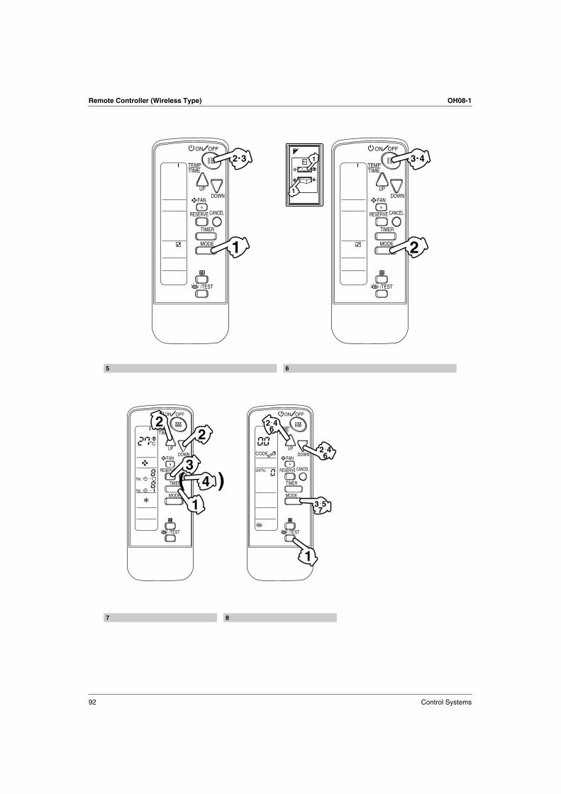
PROGRAM DRY OPERATION (Fig. 5, 6)
The function of this program is to decrease the humidity in your room with the minimum temperature
decrease.
Micro computer automatically determines TEMPERATURE and FAN SPEED.
This system does not go into operation if the room temperature is below 16°C.
⟨⟨FOR SYSTEMS WITHOUT COOL/HEAT CHANGEOVER REMOTE CONTROL SWITCH (Fig. 5)⟩⟩
Press OPERATION MODE SELECTOR button several times and select “ ” (PROGRAM
DRY OPERATION).
Press ON/OFF button.
OPERATION lamp lights up and system starts OPERATION.
ADJUSTMENT
STOPPING THE SYSTEM
Press ON/OFF button again.
OPERATION lamp goes off and the system stops OPERATION.
NOTE
Do not turn OFF power immediately after the unit stops. Then, wait no less than 5 minutes. Water is
leaking or there is something else wrong with the unit.
⟨⟨FOR SYSTEMS WITH COOL/HEAT CHANGEOVER REMOTE CONTROL SWITCH (Fig. 6)⟩⟩
Select COOLING OPERATION MODE with the COOL/HEAT CHANGEOVER REMOTE
CONTROL SWITCH.
Press OPERATION MODE SELECTOR button several times and select PROGRAM DRY
“ ”.
Press ON/OFF button.
OPERATION lamp lights up and the system starts.
STOPPING THE SYSTEM
Press ON/OFF button once again.
OPERATION lamp goes off, and the system stops OPERATION.
NOTE
Do not turn OFF power immediately after the unit stops. Then, wait no less than 5 minutes. Water is
leaking or there is something else wrong with the unit.
MOVEMENT OF THE AIR FLOW FLAP
For the following conditions, micro computer controls the air flow direction so it may be different from the
display.
Operation mode includes automatic operation.
Operation mode Cooling Heating
Operation conditions
When room temperature is lower than the set temperature
When room temperature is higher than the set temperatureAt defrost operation
When operating continuously at horizontal air flow direction
1
2
3
1
2
3
4

OH08-1 Remote Controller (Wireless Type)
Control Systems 97
2
PROGRAM TIMER OPERATION (Fig. 7)
The timer is operated in the following two ways.
Programming the stop time ( )
....The system stops operating after the set time has elapsed.
Programming the start time ( )
.... The system starts operating after the set time has elapsed.
The timer can be programmed a maximum of 72 hours.
The start and the stop time can be simultaneously programmed.
Press the TIMER MODE START/STOP button several times and select the mode on the
display.
The display flashes.
For setting the timer stop .......................................................“ ”
For setting the timer start .......................................................“ ”
Press the PROGRAMMING TIMER button and set the time for stopping or starting the
system.
When this button is pressed, the time advances by 1 hour.
When this button is pressed, the time goes backward by 1 hour.
Press RESERVE button.
The timer setting procedure ends.
The display changes from flashing light to a constant light.
NOTE
When setting the timer Off and On at the same time, repeat the above procedure from to
once again.
For example
When the timer is programmed to stop the system after 3 hours and start the system after 4 hours, the
system will stop after 3 hours and then 1 hour later the system will start.
After the timer is programmed, the display shows the remaining time.
Press the TIMER OFF button to cancel programming. The display vanishes. ( )
HOW TO SET MASTER REMOTE CONTROLLER (For VRV system)
When the system is installed as shown below, it is necessary to designate the master remote controller.
1
2
UP
DOWN
3
1 3
MODE
TIMER
RESERVE CANCEL
DOWN
UP
FAN
TIMETEMP
ON OFF
C
hr.
hr.
4
2.5
BR
C4C
65 / B
RC
4C
66

Remote Controller (Wireless Type) OH08-1
98 Control Systems
⟨⟨For Heat pump system⟩⟩
When one outdoor unit is connected with several indoor units.
⟨⟨For Heat recovery system⟩⟩
When one BS unit is connected with several indoor units.
Only the master remote controller can select HEATING, COOLING or AUTOMATIC (only Heat recovery
system) OPERATION.
When the indoor unit with master remote controller is set to “COOL”, you can switch over operation mode
between “FAN”, “DRY” and “COOL”.
When the indoor unit with master remote controller is set to “HEAT”, you can switch over operation mode
between “FAN” and “HEAT”.
When the indoor unit with master remote controller is set to “FAN”, you cannot switch operation mode.
When attempting settings than that consented above, a “peep” is emitted as a warning.
Only with Heat recovery system, you can set the indoor unit to AUTOMATIC. Attempting to do so, a “peep”
will be emitted as a warning.
How to designate the master remote controller
Continuously press the OPERATION MODE SELECTOR button for 4 seconds.
The displays showing “ ” of all slave indoor unit connected to the same outdoor unit or BS unit flash.
Press the OPERATION MODE SELECTOR button to the indoor unit that you wish to
designate as the master remote controller. Then designation is completed. This indoor
unit is designated as the master remote controller and the display showing “ ”
vanishes.
To change settings, repeat steps and .
One of these remote controllers
need s to b e d esig na ted a s the
ma ster remote controller.
Ind oor
u nit
Ou td oor u nit
B S u nitInd oor
u nit
Ou td oor u nit
One of these remote controllers
need s to b e d esig na ted a s the
ma ster remote controller.
1
2
1 2

OH08-1 Remote Controller (Wireless Type)
Control Systems 99
2
EMERGENCY OPERATION
When the remote controller does not work due to battery failure or the absence thereof, use this switch
which is located beside the discharge grille on the main unit. When the remote controller does not work, but
the battery low indicator on it is not lit, contact your dealer.
[START]
Press the EMERGENCY OPERATION switch.
The machine runs in the previous mode.
The system operates with the previously set air flow direction, and airflow rate.
[STOP]
Press the EMERGENCY OPERATION switch again.
PRECAUTIONS FOR GROUP CONTROL SYSTEM OR TWO REMOTE CONTROLLER CONTROL
SYSTEM
This system provides two other control systems beside individual control (one remote controller controls
one indoor unit) system. Confirm the following if your unit is of the following control system type.
Group control system
One remote controller controls up to 16 indoor units.
All indoor units are equally set.
Two remote controller control system
Two remote controllers control one indoor unit. (In case of group control system, one group of indoor
units.)
The unit follows individual operation.
NOTE
Cannot have two remote controllers control system with only wireless remote controllers. (It will be a
two remote controller control system having one wired and one wireless remote controllers.)
Under two remote controller control system, wireless remote controller cannot control timer operation.
Only the operating indicator lamp out of 3 other lamps on the indoor unit display functions.
Contact your Daikin dealer in case of changing the combination or setting of group control and two
remote controller control systems.
1
1•2
2
2.5
BR
C4C
65 / B
RC
4C
66

Remote Controller (Wireless Type) OH08-1
100 Control Systems
Not Malfunction of the Air Conditioner
The following symptoms do not indicate air conditioner malfunction
I. THE SYSTEM DOES NOT OPERATE
The system does not restart immediately after the ON/OFF button is pressed.
If the OPERATION lamp lights, the system is in normal condition. It does not restart immediately
because a safety device operates to prevent overload of the system. After 3 minutes, the system will
turn on again automatically.
The system does not restart immediately when TEMPERATURE SETTING button is returned to
the former position after pushing the button.
It does not restart immediately because a safety device operates to prevent overload of the system.
After 3 minutes, the system will turn on again automatically.
If the reception beep is rapidly repeated 3 times (It sounds only twice when operating normally.)
Control is set to the optional controller for centralized control.
If the defrost lamp on the indoor unit’s display is lit when heating is started.
This indication is to warn against cold air being blown from the unit. There is nothing wrong with the
equipment.
How to Diagnose Trouble Spots
See Fig. 8
I. EMERGENCY STOP
When the air conditioner stops in emergency, the run lamp on the indoor unit starts blinking. Take the
following steps yourself to read the malfunction code that appears on the display. Contact your dealer with
this code. It will help pinpoint the cause of the trouble, speeding up the repair.
Press the INSPECTION/TEST button to select the inspection mode “ ”.
“ ” appears on display and blinks. “UNIT” lights up.
Press PROGRAMMING TIMER BUTTON and change the unit number.
Press to change the unit number until the indoor unit beeps and perform the following operation according
to the number of beeps.
Number of beeps
3 short beeps .........................................................................Perform all steps from to
1 short beep ...........................................................................Perform and steps
1 long beep ............................................................................Normal state
Press OPERATION MODE SELECTOR BUTTON.
“ ” on the left-hand of the malfunction code blinks.
Press PROGRAMMING TIMER BUTTON and change the malfunction code.
Press until the indoor unit beeps twice.
Press OPERATION MODE SELECTOR BUTTON.
“ ” on the right-hand of the malfunction code blinks.
Press PROGRAMMING TIMER BUTTON and change the malfunction code.
Press until the indoor unit makes a long beep.
The malfunction code is fixed when the indoor unit makes a long beep.
Reset of the display.
Press OPERATION MODE SELECTOR BUTTON to get the display back to the normal state.
1
2
3 6
3 6
3
4
5
6
7

OH08-1 Remote Controller (Wireless Type)
Control Systems 101
2
II. IN CASE BESIDES EMERGENCY STOP
1. The unit does not operate at all.
Check if the receiver is exposed of sunlight or strong light. Keep receiver away from light.
Check if there are batteries in the remote controller. Place the batteries.
Check if the indoor unit number and wireless remote controller number are equal.
Operate the indoor unit with the remote controller of the same number.
Signal transmitted from a remote controller of a different number cannot be accepted. (If the number is not
mentioned, it is considered as “1”.)
2. The system operates but it does not sufficiently cool or heat.
If the set temperature is not proper.
If the FAN SPEED is set to L SPEED.
If the air flow angle is not proper.
Contact the place of purchase in the following case.
WARNING
When you detect a burning odor, shut OFF power immediately and contact the place of purchase. Using
the equipment in anything but proper working condition can result in equipment damage, electric shock
and/or fire.
[Trouble]
The RUN lamp of the indoor unit is flashing and the unit does not work at all.
[Remedial action]
Check the malfunction code (A1 ~ UF) on the remote control and contact the place of purchase. (See page
100.)
Number
MODE
TIMER
RESERVE CANCEL
DOWN
UP
/TEST
FAN
TIMETEMP
ON OFF
UNIT NO.
CODE
Unit No. which sensed trouble
Malfunction Code
INSPECTIONdisplay
2.5
BR
C4C
65 / B
RC
4C
66

Remote Controller (Wireless Type) OH08-1
102 Control Systems
2.5.5 InstallationCaution
Do not install more than 3 receivers in the vicinity of one another.
With 4 or more units, there is always the possibility of malfunction.
Remove the Upper Part of Receiver
Insert the screwdriver here and gently work off the upper part of the receiver.
Initial Setting
NOTES
If controlling with one remote controller, be sure to set it to "MAIN"
Set the remote controller before turning power supply on.
Address Setting
If setting multiple wireless remote controllers to operate in one room, perform address setting for the
receiver and the wireless remote controller.
PRECAUTIONS
Set the Unit NO. of the receiver and the wireless remote controller to be equal.
If the settings differs, the signal from the remote controller cannot be transmitted.
When using both a wired and a wireless
remote controller for 1 indoor unit, the
wired controller should be set to MAIN.
And the wireless remote controller should
be set to SUB.
Main Remote Controller(Factory Set)
S
Sub Remote Controller
S
Change the MAIN/SUB changeover switch
→1→2→3→4→5→6
NO.2
SS2
3
Wirelessaddressswitch(SS2)
UP
<Setting from the remote controller>
DOWN
/TEST
2
Referring to the table below, set the wireless address switch (SS2) on the PC board.
2
1 Hold down the button and the button for at least 4 seconds to get
the Field Set mode. (indicated in the display area in the figure at right).
Press the button and select a multiple setting (A/b). Each time the button
is pressed the display switches between "A" and "b".
Press the " " button and " " button to set the
Address can be set from 1 to 6, but set it to 1~3 and to same address as
the receiver. (The receiver does not work with address 4~6.)
Press the button to enter the setting.
Hold down the button for at least 1 second to quit the Field Set
mode and return to the normal display.
3
4
1
Setting the receiver (lt is fuctory set to "1")
3
NO.1
3
2 FAN
/ TEST
SS2
2
Setting the address of wireless remote controller (It is factory set to "1")
NO.3
5
11
Unit No.
SS2
RESERVE

OH08-1 Remote Controller (Wireless Type)
Control Systems 103
2
SAFETY CONSIDERATIONS
Please read this "SAFETY CONSIDERATIONS" carefully before installing air conditioning equipment and
be sure to install it correctly.
After completing the installation, make sure at start up operation that the unit operates properly. Please
instruct the customer how to operate the unit and keep maintenance.
CAUTION Confirm that following conditions are satisfied prior to installation.
Ensure that nothing interrupts the operation of the wireless remote controller. (Ensure that there is
neither a source of light nor fluorescent lamp near the receiver. Also, ensure that the receiver is not
exposed of direct sun light.)
Ensure that the operation display lamp and other indicators are easy to see.
For Ceiling Installation
(1) Prepare the Ceiling for the Receiver
Open a hole in the ceiling for the receiver. (Use the provided ceiling installation pattern.)
(2) Wire the Indoor Unit and Fix the Lower Part
Install the winged bar to the lower part and fit the part with the attached screws, Then, wire (field
supplied) accordingly.
Mode
5
SETTING
ON/OFF
SWING
4TIMER
CANCEL
3
DOWN
Multiplesetting
MODE
RESERVE
1/ TEST
FAN
TEMP
TIME
Address
2
UP
Multiple setting A/bWhen the indoor unit is being operating by outside control (central remote controller,
etc.), it sometimes does not respond to ON/OFF and temperature setting commands
from this remote controller. Check what setting the customer wants and make the
multiple setting as shown below.
Remote controller display
For other than on left
All commands accepted (2 SHORT BEEPS)
Multiple setting
All items displayed.
Remote controller
b: Multi System
Commands other than ON/OFF and temperature setting accepted. (1 LONG BEEP or 3 SHORT BEEPS emitted)
A: Standard
Indoor unit
Operations remain displayed shortly after execution.
To control other air conditions and units
66
(cei
ling
open
ing)
49
116
(Ceiling opening)106
(Ser
vice
spa
ce)
90
more
than
Transmission Wiring
Mounting Screw
Winged Bar
(attached)Lower Part
P1
(attached)
(Field Wiring)
Connect the P1 and P2 terminals on
the rear of the lower part to the
P1 and P2 terminals on the indoor
unit. The P1 and P2 terminals have
no polarity.
Indoor Unit
P2
2.5
BR
C4C
65 / B
RC
4C
66

Remote Controller (Wireless Type) OH08-1
104 Control Systems
Insert the lower part into the opening in the ceiling, first by pressing the wings inward to fit the hole and
then by pushing from the screws until it sits flat on the ceiling.
Tighten the screws until the lower part is fixed in place.
Rettach the upper part of receiver.
For Wall Mounting
(1) Wire the Indoor Unit
Tighten both screws evenly. Overtightening
may deform the case and possibly make it
harder to install the upper part.
Install the upper part on the lower part
being careful parts are facing in the
correct direction. And, test the emergency
run button.
Switch Box
Transmission Wiring
P1
Connect the P1 and P2 terminals on the rear of the lower part to the
P1 and P2 terminals on the indoor unit.
Neither of the terminals is polarized, so it is not important if
connections are crossed.
Indoor Unit
P2
(Part to be procured in the field)
Lower Part

OH08-1 Remote Controller (Wireless Type)
Control Systems 105
2
(2) Fix the Lower Part
Install the lower part on theh switch box (field supplied part)
(3) Rettach the Upper Part of Remote Controller
2P018568
(Part to be procured
Mounting screw
Lower Part
in the field)
(attached)
Switch Box
Select as flat a place ash possible to install the lower part. Also, be
aware of the fact that overtightening the screws (attached) may
deform the case and possibly make it harder to install the upper part.
NOTES)
Install the upper part on the lower part
being careful parts are facing in the
correct direction.
And, test the emergency run button.
1. The switch box and wiring are not included.
2. Do not directly touch the PC board with your hand.
⟨⟨Precautions on transmission wiring⟩⟩
0.75~1.25mm2
max 200m (See Note 1)
Size
Sheathed wire (2 wire)
Wiring length
Wiring type
1. Keep wires to less than 200m total when using 2 remote controller
(wired or wireless) and when not.
When wiring, run the wiring away the power supply wiring in order to avoid receiving
electric noise (external noise).
When wiring, refer to the wiring diagram of indoor unit (attached to indoor unit) as well.
WIRING SPECIFICATION
NOTE)
1
2
2.5
BR
C4C
65 / B
RC
4C
66
Recommended


![HTTPS--HTTP Server and Client with SSL 3 · 4. iphttpclientsecure-ciphersuite[3des-ede-cbc-sha][rc4-128-sha][rc4-128-md5][des-cbc-sha] 5. end 6. showiphttpclientsecurestatus DETAILED](https://img.dokumen.tips/doc/110x75/5f8d2751b05f8d196545892e/https-http-server-and-client-with-ssl-3-4-iphttpclientsecure-ciphersuite3des-ede-cbc-sharc4-128-sharc4-128-md5des-cbc-sha.jpg)