arX
iv:1
008.
3776
v1 [
cs.IT
] 23
Aug
201
01
Green Modulations in Energy-Constrained
Wireless Sensor Networks
Jamshid Abouei†, Konstantinos N. Plataniotis††, and Subbarayan Pasupathy††
† Department of Electrical Engineering, Yazd University, Yazd, Iran, Email: [email protected]
†† The Edward S. Rogers Sr. Dept. of ECE, University of Toronto,Toronto, ON M5S 3G4, Canada
Emails:kostas, [email protected]
Abstract
Due to the unique characteristics of sensor devices, findingthe energy-efficient modulation with a low-
complexity implementation (refereed to asgreen modulation) poses significant challenges in the physical layer
design of Wireless Sensor Networks (WSNs). Toward this goal, we present an in-depth analysis on the energy
efficiency of various modulation schemes using realistic models in the IEEE 802.15.4 standard to find the optimum
distance-based scheme in a WSN over Rayleigh and Rician fading channels with path-loss. We describe a proactive
system model according to a flexible duty-cycling mechanismutilized in practical sensor apparatus. The present
analysis includes the effect of the channel bandwidth and the active mode duration on the energy consumption of
popular modulation designs. Path-loss exponent and DC-DC converter efficiency are also taken into consideration.
In considering the energy efficiency and complexity, it is demonstrated that among various sinusoidal carrier-based
modulations, the optimized Non-Coherent M-ary Frequency Shift Keying (NC-MFSK) is the most energy-efficient
scheme in sparse WSNs for each value of the path-loss exponent, where the optimization is performed over the
modulation parameters. In addition, we show that the On-OffKeying (OOK) displays a significant energy saving
as compared to the optimized NC-MFSK in dense WSNs with smallvalues of path-loss exponent.
The work was supported in part by an Ontario Research Fund (ORF) project entitled “Self-Powered Sensor Networks”. The work of
Jamshid Abouei was performed when he was with the Dept. of ECE, University of Toronto, Toronto, ON M5S 3G4, Canada. The material
in this paper was presented in part to ICASSP’2010 conference, March 2010 [1].

2
Index Terms
Wireless sensor networks, energy efficiency, green modulation, M-ary FSK, Ultra-Wideband (UWB) modulation.
I. INTRODUCTION
Wireless Sensor Networks (WSNs) have been recognized as a collection of distributed nodes to support
a broad range of applications, including monitoring, health-care and detection of environmental pollution.
In such configuration, sensors are typically powered by limited-lifetime batteries which are hard to be
replaced or recharged. On the other hand, since a large number of sensors are deployed over a region, the
circuit energy consumption is comparable to the transmission energy due to the short distance between
nodes. Thus, minimizing the total energy consumption in both circuits and signal transmission is a crucial
task in designing a WSN [1], [2]. Central to this study is to find energy-efficient modulations in the
physical layer of a WSN to prolong the sensor lifetime. For this purpose, energy-efficient modulations
should be simple enough to be implemented by state-of-the-art low-power technologies, but still robust
enough to provide the desired service. In addition, since sensor devices frequently switch from sleep
mode to active mode, modulator circuits should have fast start-up times. We refer to these simple and
low-energy consumption schemes asgreen modulations.
In recent years, several energy-efficient modulations havebeen studied in the physical layer of WSNs
(e.g., [3], [4]). In [3] the authors compare the battery power efficiency of PPM and OOK based on the Bit
Error Rate (BER) and the cutoff rate of a WSN over path-loss Additive White Gaussian Noise (AWGN)
channels. Reference [4] investigates the energy efficiencyof a centralized WSN with an adaptive MQAM
scheme. However, adaptive approaches impose some additional system complexity due to the multi-level
modulation formats plus the channel state information fed back from the sink node to the sensor node.
Most of the pioneering work on energy-efficient modulations, including research in [3], has focused only
on minimizing the average energy consumption per information bit, ignoring the effect of the bandwidth
and transmission time duration. In a practical WSN, however, it is shown that minimizing the total energy
consumption depends strongly on the active mode duration and the channel bandwidth [5].

3
In this paper, we present an in-depth analysis (supported bynumerical results) of the energy efficiency
of various modulation schemes considering the effect of the“channel bandwidth” and the “active mode
duration” to find the distance-based green modulations in a proactiveWSN. For this purpose, we describe
the system model according to a flexible duty-cycling process utilized in practical sensor devices. This
model distinguishes our approach from existing alternatives [3]. New analysis results for comparative
evaluation of popular modulation designs are introduced according to the realistic parameters in the
IEEE 802.15.4 standard [6]. We start the analysis based on a Rayleigh flat-fading channel with path-
loss which is a feasible model in static WSNs [3]. Then, we evaluate numerically the energy efficiency
of sinusoidal carrier-based modulations operating over the more general Rician model which includes a
strong direct Line-Of-Sight (LOS) path. Path-loss exponent and DC-DC converter efficiency (in a non-
ideal battery model) are also taken into consideration. It is demonstrated that among various sinusoidal
carrier-based modulations, the optimized Non-Coherent M-ary Frequency Shift Keying (NC-MFSK) is
the most energy-efficient scheme in sparse WSNs for each value of the path-loss exponent, where the
optimization is performed over the modulation parameters.In addition, we show that the On-Off Keying
(OOK) has significant energy saving as compared to the optimized NC-MFSK in dense WSNs with small
values of path-loss exponent. NC-MFSK and OOK have the advantage of less complexity and cost in
implementation than MQAM and Offset-QPSK used in the IEEE 802.15.4 protocol, and can be considered
as green modulations in WSN applications.
The rest of the paper is organized as follows. In Section II, the proactive system model and assumptions
are described. A comprehensive analysis of the energy efficiency for popular sinusoidal carrier-based and
UWB modulations is presented in Sections III and V. Section IV provides some numerical evaluations
using realistic models to confirm our analysis. Finally in Section VI, an overview of the results and
conclusions are presented.
For convenience, we provide a list of key mathematical symbols used in this paper in Table I.

4
TABLE I
L IST OF NOTATIONS
B: Bandwidth b: Number of bits per symbol
Beff : Bandwidth efficiency Et: Energy per symbol
d: Distance EN : Total energy consumption forN -bit
M : Constellation size hi: Fading channel coefficient
Ps: Symbol error rate Ld: Channel gain factor in distanced
Ts: Symbol duration N : Number of transmitted bits in active mode period
Tac: Active mode period Pc: Total circuit power consumption
Ttr: Transient mode period Pt: RF transmit power consumption per symbol
η: Path-loss exponent χe: Power transfer efficiency in DC-DC converter
Ω = E[
|hi|2]
γi: Instantaneous SNR
E[ . ]: Expectation operator Pr.: Probability of the given event
t
Active Mode
slTac sl
T
acTsl ac
T
Active Mode
NT
Fig. 1. A practical duty-cycling process in a proactive WSN.
II. SYSTEM MODEL AND ASSUMPTIONS
In this work, we consider a proactive wireless sensor system, in which a sensor node transmits an
equal amount of data per time unit to a designated sink node. The sensor and sink nodes synchronize
with one another and operate in a duty-cycling manner as depicted in Fig 1. Duringactive modeperiod
Tac, the sensed analog signal is first digitized by an Analog-to-Digital Converter (ADC), and anN-bit
binary message sequenceMN , aiNi=1 is generated, whereN is assumed to be fixed. The bit stream is
modulated using a pre-determined modulation scheme1 and then transmitted to the sink node. Finally, the
1Because the main goal of this work is to find the distance-based green modulations, and noting that the source/channel coding increase
the complexity and the power consumption, in particular codes with iterative decoding process, the source/channel coding are not considered.

5
sensor node returns to thesleep mode, and all the circuits are powered off for the sleep mode duration Tsl.
We denoteTtr as thetransient modeduration consisting of the switching time from sleep mode toactive
mode (i.e.,Tsl→ac) plus the switching time from active mode to sleep mode (i.e., Tac→sl), whereTac→sl
is short enough to be negligible. Under the above considerations, the sensor/sink nodes have to process
one entireN-bit messageMN during 0 ≤ Tac ≤ TN − Tsl − Ttr, whereTN , Ttr + Tac + Tsl is assumed
to be fixed for each modulation, andTtr ≈ Tsl→ac. Note thatTac is an influential factor in choosing the
energy-efficient modulation, since it directly affects thetotal energy consumption as we will show later.
We assume that both sensor and sink devices include a Direct Current to Direct Current (DC-DC)
converter to generate a desired supply voltage from the embedded batteries. An DC-DC converter is
specified by itspower transfer efficiencydenoted byχe < 1. In addition, we assume a linear model
for batteries with a small discharge current, meaning that the stored energy will be completely used
or released. This model is reasonable for the proposed duty-cycling process, as the batteries which are
discharged during active mode durations can recover their wasted capacities during sleep mode periods.
Since sensor nodes in a typical WSN are densely deployed, thedistance between nodes is normally short.
Thus, the total circuit power consumption, defined byPc , Pct + Pcr, is comparable to the RF transmit
power consumption denoted byPt, wherePct andPcr represent the circuit power consumptions for the
sensor and sink nodes, respectively. In considering the effect of the power transfer efficiency, the total
energy consumption in the active mode period, denoted byEac, is given by
Eac =Pc + Pt
χe
Tac, (1)
whereTac is a function ofN and the channel bandwidth as we will show in Section III. Also, it is shown
in [7] that the power consumption during the sleep mode duration Tsl is much smaller than the power
consumption in the active mode (due to the low sleep mode leakage current) to be negligible. As a result,
the energy efficiency, referred to as the performance metric of the proposed WSN, can be measured by
the total energy consumption in each periodTN corresponding toN-bit messageMN as follows:
EN ≈ 1
χe
[(Pc + Pt)Tac + PtrTtr] , (2)

6
wherePtr
χeTtr is the circuit energy consumption during the transient modeperiod. We use (2) to investigate
and compare the energy efficiency of various modulation schemes in the subsequent sections.
Channel Model: It is shown that for short-range transmissions including the wireless sensor networking,
the root mean square (rms) delay spread is in the range of ns [8] (and ps for UWB applications [9]) which
is small compared to the symbol durationTs = 16 µs obtained from the bandwidthB = 1Ts
= 62.5 KHz
in the IEEE 802.15.4 standard [6, p. 49]. Thus, it is reasonable to expect a flat-fading channel model for
WSNs. Under the above considerations, the channel model between the sensor and sink nodes is assumed
to be Rayleigh flat-fading with path-loss. This assumption is used in many works in the literature (e.g.,
see [3] for WSNs). We denote the fading channel coefficient corresponding to symboli ashi, where the
amplitude∣
∣hi
∣
∣ is Rayleigh distributed with the probability density function (pdf) f|hi|(r) =2rΩe−
r2
Ω , r ≥ 0,
whereΩ , E [|hi|2] [10]. To model the path-loss of a link where the transmitter and receiver are separated
by distanced, let denotePt andPr as the transmitted and the received signal powers, respectively. For
a ηth-power path-loss channel, the channel gain factor is given by
Ld ,Pt
Pr
= MldηL1, with ηmin ≤ η ≤ ηmax, (3)
whereMl is the gain margin which accounts for the effects of hardwareprocess variations andL1 ,(4π)2
GtGrλ2
is the gain factor atd = 1 meter which is specified by the transmitter and receiver antenna gainsGt
and Gr, and wavelengthλ (e.g., [3], [5]). As a result, when both fading and path-lossare considered,
the instantaneous channel coefficient becomesGi ,hi√Ld
. Denotingxi(t) as the transmitted signal with
energyEt, the received signal at the sink node is given byyi(t) = Gixi(t) + zi(t), wherezi(t) is AWGN
with two-sided power spectral density given byN0
2. Thus, the instantaneous Signal-to-Noise Ratio (SNR)
corresponding to an arbitrary symboli can be computed asγi =|Gi|2EtN0
. Under the assumption of a Rayleigh
fading channel,γi is chi-square distributed with 2 degrees of freedom, with pdf fγ(γi) =1γexp
(
−γiγ
)
,
whereγ , E[|Gi|2] EtN0= Ω
Ld
EtN0
denotes the average received SNR.

7
III. ENERGY EFFICIENCY ANALYSIS OF SINUSOIDAL CARRIER-BASED MODULATIONS
In this section, we analyze the energy and bandwidth efficiency of three popular sinusoidal carrier-based
modulations, namely MFSK, MQAM and OQPSK, over a Rayleigh flat-fading channel with path-loss.
FSK is used in many low-complexity and energy-constrained wireless systems and some IEEE standards
(e.g., [11]), whereas MQAM is used in modem and digital videoapplications. Also, OQPSK is used in
the IEEE 802.15.4 standard which is the industry standard for WSNs. In the sequel and for simplicity of
the notation, we use the superscripts ‘FS’, ‘QA’ and ‘OQ’ forMFSK, MQAM and OQPSK, respectively.
M-ary FSK: An M-ary FSK modulator withM = 2b orthogonal carriers benefits from the advantage
of using the Direct Digital Modulation (DDM) approach, meaning that it does not need the mixer and
the Digital to Analog Converter (DAC). This property makes MFSK has a faster start-up time than the
other modulation schemes. Let denote∆f = 1ζTFS
sas the minimum carrier separation with the symbol
durationT FSs , whereζ = 2 for coherent andζ = 1 for non-coherent FSK [12, p. 114]. In this case,
the channel bandwidth is obtained asB ≈ M ×∆f , whereB is assumed to be fixed for all sinusoidal
carrier-based modulations. DenotingBFSeff as thebandwidth efficiencyof MFSK defined as the ratio of
data rateRFS = bTFSs
(b/s) to the channel bandwidth, we have
BFSeff ,
RFS
B=
ζ log2M
M, b/s/Hz. (4)
It can be seen that using a small constellation sizeM avoid losing more bandwidth efficiency in MFSK.
To address the effect of increasingM on the energy efficiency, we first derive the relationship betweenM
and the active mode durationT FSac . Since, we haveb bits during each symbol periodT FS
s , we can write
T FSac =
N
bT FSs =
MN
ζB log2M. (5)
Recalling thatB andN are fixed, an increase inM results in an increase inT FSac . However, the maximum
value ofT FSac is bounded byTN −T FS
tr as illustrated in Fig. 1. Thus,Mmax , 2bmax in MFSK is calculated
by the following non-linear equation:
Mmax
log2Mmax
=ζB
N(TN − T FS
tr ). (6)

8
At the receiver side, the received MFSK signal can be detected coherently to provide an optimum
performance. However, the MFSK coherent detection requires the receiver to obtain a precise frequency
and carrier phase reference for each of the transmitted orthogonal carriers. For largeM , this would increase
the complexity of the detector which makes a coherent MFSK receiver very difficult to implement. Thus,
most practical MFSK receivers use non-coherent detectors2. To analyze the energy efficiency of a NC-
MFSK, we first deriveEFSt , the transmit energy per symbol, in terms of a given average Symbol Error
Rate (SER) denoted byPs. It is shown in [14, Lemma 2] that the average SER of a NC-MFSK is upper
bounded by
Ps = 1−(
1− 1
2 + γFS
)M−1
, (7)
whereγFS = ΩLd
EFSt
N0. As a result, the transmit energy consumption per symbol is obtained from the above
Ps as
EFSt , PFS
t T FSs =
[
(
1− (1− Ps)1
M−1
)−1
− 2
] LdN0
Ω. (8)
In considering the effect of the DC-DC converter and using (5), the output energy consumption of
transmittingN-bit during T FSac is computed as
PFSt
χe
T FSac =
T FSac
T FSs
EFSt
χe
=
[
(
1− (1− Ps)1
M−1
)−1
− 2
] LdN0
χeΩ
N
log2M. (9)
On the other hand, the total circuit energy consumption of the sensor/sink devices duringT FSac is obtained
from PFSct +PFS
cr
χeT FSac . For the sensor node with the MFSK modulator, we denote the power consumption of
frequency synthesizer, filters and power amplifier asPFSSy , PFS
F ilt andPFSAmp, respectively. In this case,
PFSct = PFS
Sy + PFSF ilt + PFS
Amp. (10)
It is shown that the relationship betweenPFSAmp and the transmission power of an MFSK signal isPFS
Amp =
αFSPFSt , whereαFS is determined based on the type of the power amplifier. For instance for a class
B power amplifier,αFS = 0.33 [5]. For the circuit power consumption of the sink node, we use the
fact that the optimum NC-MFSK demodulator consists of a bankof M matched filters, each followed
2For the purpose of comparison, the energy efficiency of acoherentMFSK is fully analyzed in Appendix I in [13].

9
by an envelope detector [15]. In addition, we assume that thesink node uses a Low-Noise Amplifier
(LNA) which is generally placed at the front-end of a RF receiver circuit, an Intermediate-Frequency
Amplifier (IFA), and an ADC, regardless of type of deployed modulation. Thus, denotingPFSLNA, PFS
F ilr,
PFSED, PFS
IFA and PFSADC as the power consumption of LNA, filters, envelope detector,IF amplifier and
ADC, respectively, the circuit power consumption of the sink node is obtained as
PFScr = PFS
LNA +M × (PFSF ilr + PFS
ED) + PFSIFA + PFS
ADC . (11)
Moreover, it is shown that the power consumption during the transient mode periodT FStr is governed
by the frequency synthesizer in both sensor/sink nodes [5].Thus, the energy consumption duringT FStr is
obtained asPFStr
χeT FStr = 2
PFSSy
χeT FStr [8]. Substituting (5) and (9) in (2), the total energy consumption of a
NC-MFSK scheme for transmittingN-bit in each periodTN and for a givenPs is obtained as
EFSN = (1 + αFS)
(
[
1− (1− Ps)1
M−1
]−1
− 2
) LdN0
χeΩ
N
log2M+
1
χe
[
(PFSc − PFS
Amp)MN
B log2M+ 2PFS
Sy TFStr
]
, (12)
with the fact thatLd = MldηL1. Thus, the optimization goal is to determine the optimum constellation
sizeM , such that the objective functionEFSN can be minimized, i.e.,
M = arg minM
EFSN
subject to
2 ≤ M ≤ Mmax
ηmin ≤ η ≤ ηmax
d > 0,
(13)
whereMmax derived from (6). To solve this optimization problem, we prove that (12) is a monotonically
increasing function ofM for every value ofd and η. It is seen that the second term in (12) is a
monotonically increasing function ofM . Also, from the first term in (12), we have(
[
1− (1− Ps)1
M−1
]−1
− 2
)
1
log2M=
(
[
1− e1
M−1ln(1−Ps)
]−1
− 2
)
1
log2M(14)
(a)≈
(
[
1− e−Ps
M−1
]−1
− 2
)
1
log2M(15)
(b)≈
(
M − 1
Ps
− 2
)
1
log2M, (16)

10
where(a) comes from the approximationln(1− z) ≈ −z, |z| ≪ 1, and the fact thatPs scales aso(1).
Also, (b) follows from the approximatione−z =∑∞
n=0(−1)n zn
n!≈ 1 − z, |z| ≪ 1. It is concluded from
(16) that the first term in (12) is also a monotonically increasing function ofM . As a result, the minimum
total energy consumptionEFSN is achieved atM = 2 for all values ofd andη.
M-ary QAM: For M-ary QAM with the square constellation, eachb = log2M bits of the message is
mapped to the symbolSi, i = 0, 1, ...,M − 1, with the symbol durationTQAs . Assuming the raised-cosine
filter is used for the pulse shaping, the channel bandwidth ofMQAM is given byB ≈ 1
2TQAs
. Thus, using
the data rateRQA = b
TQAs
, the bandwidth efficiency of MQAM is obtained asBQAeff , RQA
B= 2 log2M
which is a logarithmically increasing function ofM . To address the impact ofM on the energy efficiency,
we derive the active mode durationTQAac in terms ofM as follows:
TQAac =
N
bTQAs =
N
2B log2M. (17)
It is seen that an increase inM results in a decrease inTQAac . Also compared to (5) for the NC-MFSK, it
is concluded thatTQAac = 1
2MT FSac . Interestingly, it seems that the large constellation sizes M would result
in the lower energy consumption due to the smaller values ofTQAac . However, as we will show later, the
total energy consumption of a MQAM is not necessarily a monotonically decreasing function ofM . For
this purpose, we obtain the transmit energy consumptionPQAt TQA
ac with a similar argument as for MFSK.
It is shown in [16, pp. 226] and [13] that the average SER of a coherent MQAM is upper bounded by
Ps =4(M − 1)
3γQA + 2(M − 1)
(
1− 1√M
)
, (18)
whereγQA = ΩLd
EQAt
N0denotes the average received SNR with the energy per symbolEQA
t . As a result,
EQAt , PQA
t TQAs =
2(M − 1)
3
[
2
(
1− 1√M
)
1
Ps
− 1
] LdN0
Ω. (19)
In considering the effect of the DC-DC converter, the outputenergy consumption of transmittingN-bit
during the active mode period is computed as
PQAt
χe
TQAac =
TQAac
TQAs
EQAt
χe
=2(M − 1)
3
[
2
(
1− 1√M
)
1
Ps
− 1
] LdN0
χeΩ
N
log2M, (20)

11
which is a monotonically increasing function ofM for every value ofPs, d and η. For the sensor node
with the MQAM modulator,
PQAct = PQA
DAC + PQASy + PQA
Mix + PQAFilt + PQA
Amp, (21)
wherePQADAC andPQA
Mix denote the power consumption of DAC and mixer, respectively. It is shown that
PQAAmp = αQAPQA
t , whereαQA = ξ
ϑ− 1 with ξ = 3
√M−1√M+1
andϑ = 0.35 [5]. In addition, the circuit power
consumption of the sink with the coherent MQAM is obtained as
PQAcr = PQA
LNA + PQAMix + PQA
Sy + PQAFilr + PQA
IFA + PQAADC . (22)
Also, with a similar argument as for MFSK, we assume that the circuit power consumption during transient
mode periodTQAtr is governed by the frequency synthesizer. As a result, the total energy consumption of
a coherent MQAM for transmittingN-bit in each periodTN is obtained as
EQAN = (1 + αQA)
2(M − 1)
3
[
2
(
1− 1√M
)
1
Ps
− 1
] LdN0
χeΩ
N
log2M+
1
χe
[
(PQAc −PQA
Amp)N
2B log2M+ 2PQA
Sy TQAtr
]
. (23)
Although, there is no constraint on the maximum sizeM for MQAM, to make a fair comparison to the
MFSK scheme, we use the sameMmax as MFSK. Taking this into account, the optimization problemis
to determine the optimumM ∈ [4,Mmax] subject tod > 0 andηmin ≤ η ≤ ηmax, such thatEQAN can be
minimized.
It is seen that the first term in (23) is a monotonically increasing function ofM for every value ofPs,
d and η, while the second term is a monotonically decreasing function of M which is independent of
d and η. For the above optimization and for a givenPs, we have two following scenarios based on the
distanced:
Case 1: For large values ofd where the first term in (23) is dominant, the objective function EQAN is a
monotonically increasing function ofM and is minimized atM = 4, equivalent to the 4-QAM scheme.
Case 2: Let assume thatd is small enough. One possible case may happen is when the total energy
consumptionEQAN for small sizesM is governed by the second term in (23). For this situation, either the

12
TABLE II
SYSTEM EVALUATION PARAMETERS
χe = 0.8 N0 = −180 dBm PDAC = 7 mw
B = 62.5 KHz PED = 3 mw PADC = 7 mw
Ml = 40 dB PSy = 10 mw PMix = 7 mw
L1 = 30 dB PFilt = 2.5 mw PLNA = 9 mw
Ω = 1 PFilr = 2.5 mw PIFA = 3 mw
objective function behaves as a monotonically decreasing function ofM for every value ofM , or for a
large constellation sizeM , the first term would be dominant, meaning thatEQAN increases whenM grows.
In the former scenario, the optimumM is achieved atM = Mmax; whereas in the latter scenario, there
exists a minimum value forEQAN , where the optimumM for this point is obtained by the intersection
between the first and second terms, i.e.,
(1 + αQA)2(M − 1)
3
[
2
(
1− 1√M
)
1
Ps
− 1
] LdN0
χeΩ
N
log2M=
1
χe
[
N(PQAc −PQA
Amp)
2B log2M+ 2PQA
Sy TQAtr
]
.
Since,Ps scales aso(1) and ignoring the termPQASy T
QAtr to simplify our analysis, the optimumM which
minimizes (23) is obtained by the following equation:
M − 1−√M +
1√M
≈ φ(d, η)
1 + αQA, (24)
whereφ(d, η) ,PQAc −PQA
Amp
2B3PsΩ4LdN0
and the fact thatαQA is a function ofM .
To gain more insight to the above optimization problem, we use a specific numerical example with the
simulation parameters summarized in Table II3. We assumePs = 10−3, 4 ≤ M ≤ 64 and 2.5 ≤ η ≤ 6.
Fig. 2 illustrates the total energy consumption of MQAM versusM for different values ofd. It is seen that
EQAN exhibits different trends depending on the distanced and the path-loss exponentη. For instance, for
large values ofd andη, EQAN is an increasing function ofM , where the optimum value ofM is achieved
at M = 4 as expected. This is because, in this case, the first term in (23) corresponding to the RF signal
energy consumption dominatesEQAN . Table III details the optimum values ofM which minimizesEQA
N for
3For more details in the simulation parameters, we refer the reader to [13] and its references.

13
TABLE III
OPTIMUM M IN THE MQAM OPTIMIZATION PROBLEM FORPs = 10−3 AND DIFFERENT VALUES OFd AND 2.5 ≤ η ≤ 6
d (m) η = 2.5 η = 3 η = 4 η = 5 η = 6
1 64 64 64 64 64
10 64 64 43 10 4
20 64 50 8 4 4
40 43 13 4 4 4
80 14 5 4 4 4
100 10 4 4 4 4
150 6 4 4 4 4
200 5 4 4 4 4
some values of1 ≤ d ≤ 200 m and2.5 ≤ η ≤ 6. We use these results to compare the energy efficiency
of the optimized MQAM with the other schemes in the subsequent sections.
Offset-QPSK: For performance comparison, we choose the conventional OQPSK modulation which is
used as a reference in the IEEE 802.15.4/ZigBee protocols. We also follow the same differential OQPSK
structure mentioned in [6, p. 50] to eliminate the need for a coherent phase reference at the sink node. For
this configuration, the channel bandwidth and the data rate are determined byB ≈ 1
TOQs
andROQ = 2
TOQs
,
respectively. As a result, the bandwidth efficiency of OQPSKis obtained asBOQeff , ROQ
B= 2 (b/s/Hz).
Since we have 2 bits in each symbol periodTOQs , it is concluded that
TOQac =
N
2TOQs =
N
2B. (25)
Compared to (5) and (17), we haveTOQac = (log2M)TQA
ac with M ≥ 4, while for the optimized MFSK,
TOQac = 1
4T FSac . More precisely, it is revealed thatTQA
ac < TOQac < T FS
ac . To determine the transmit energy
consumption of the differential OQPSK scheme, we deriveEOQt in terms of the average SER. It is shown
in [17] and [13] that the average SER of the differential OQPSK is upper bounded by
Ps =
√
1 +√2
2
4
(2−√2)γOQ + 4
, (26)
where γOQ = ΩLd
EOQt
N0. With a similar argument as for MFSK and MQAM, the energy consumption of

14
0 10 20 30 40 50 60 7010
−1
100
M
Tot
al E
nerg
y C
onsu
mpt
ion
(Jou
le)
Ps=10−3 , η=2.5
d=50 m
d=10 m
d=100 m
d=150 m
d=200 m
(a)
0 10 20 30 40 50 60 7010
−1
100
101
102
103
M
Tot
al E
nerg
y C
onsu
mpt
ion
(Jou
le)
Ps=10−3, η=3.5
d=150 m
d=200 m
d=100 m
d=50 m
d=10 m
(b)
Fig. 2. Total energy consumptionEQAN vs. M over a Rayleigh fading channel with path-loss forPs = 10
−3, a) η = 2.5 ,
and b)η = 3.5.
transmittingN-bit during TOQac is computed as
POQt
χe
TOQac =
TOQac
TOQs
EOQt
χe
=
1
2−√2
4
Ps
√
1 +√2
2− 4
LdN0
χeΩ
N
2. (27)
In addition, for the sensor node with the OQPSK modulator,POQct ≈ POQ
DAC+POQSy +POQ
Mix+POQFilt+POQ
Amp,

15
where we assume that the power consumption of the differential encoder is negligible, andPOQAmp =
αOQPOQt , with αOQ = 0.33. In addition, the circuit power consumption of the sink withthe differential
detection OQPSK is obtained asPOQcr = POQ
LNA + POQMix + POQ
Sy + POQFilr + POQ
IF + POQADC . As a result, the
total energy consumption of a differential OQPSK system fortransmittingN-bit in each periodTN is
obtained as
EOQN = (1 + αOQ)
1
2−√2
4
Ps
√
1 +√2
2− 4
LdN0
χeΩ
N
2+
1
χe
[
(POQc − POQ
Amp)N
2B+ 2POQ
Sy TOQtr
]
.
(28)
IV. NUMERICAL RESULTS
In this section, we present some numerical evaluations using realistic parameters from the IEEE 802.15.4
standard and state-of-the art technology to confirm the energy efficiency analysis discussed in Section III.
We assume that all the modulations operate in the carrier frequencyf0 =2.4 GHz Industrial Scientist and
Medical (ISM) unlicensed band utilized in the IEEE 802.15.4standard [6]. According to the FCC 15.247
RSS-210 standard for United States/Canada, the maximum allowed antenna gain is 6 dBi [18]. In this
work, we assume thatGt = Gr = 5 dBi. Thus for thef0 =2.4 GHz,L1 (dB) , 10 log10
(
(4π)2
GtGrλ2
)
≈ 30 dB,
whereλ , 3×10⁸
f0= 0.125 m. We assume that in each periodTN , the data frameN = 1024 bytes (or
equivalentlyN = 8192 bits) is generated for transmission for all the modulations, whereTN is assumed to
be 1.4 s. The channel bandwidth is set to theB = 62.5 KHz, according to the IEEE 802.15.4 standard [6,
p. 49]. In addition, we assume that the path-loss exponent isin the range of2.5 to 6 4. We use the system
parameters summarized in Table II for simulations. It is concluded from Mmax
log2 Mmax= ζB
N(TN − T FS
tr ) that
Mmax ≈ 64 (or equivalentlybmax ≈ 6) for NC-MFSK. Since, there is no constraint on the maximumM
in MQAM, we choose4 ≤ M ≤ 64 for MQAM to be consistent with MFSK.
Fig. 3 compares the energy efficiency of the modulation schemes investigated in Section III versusM
for Ps = 10−3, η = 3.5 and different values ofd. It is revealed from Fig. 3-a that forM < 35, NC-MFSK
4 η = 2 is regarded as a reference state for the propagation in free space and is unattainable in practice. Also,η = 4 is for relatively
lossy environments, and for indoor environments, the path-loss exponent can reach values in the range of 4 to 6.

16
0 10 20 30 40 50 60 7010
−2
10−1
100
101
102
103
M
Tot
al E
nerg
y C
onsu
mpt
ion
(Jou
le)
d=10 m
Non−Coherent MFSKMQAMCoherent MFSK
4QAM
Non−Coherent 4FSK
Coherent 4FSK
Differential OQPSK
(a)
0 10 20 30 40 50 60 7010
0
101
102
103
M
Tot
al E
nerg
y C
onsu
mpt
ion
(Jou
le)
d=100 m
Non−Coherent MFSKMQAMCoherent MFSK
Coherent 4FSK
Differential OQPSK
Non−Coherent 4FSK
4QAM
(b)
Fig. 3. Total energy consumption of transmittingN -bit vs. M for MFSK, MQAM and differential OQPSK over a Rayleigh
fading channel with path-loss andPs = 10−3, a) d = 10 m, and b)d = 100 m.

17
TABLE IV
ENERGY-EFFICIENT MODULATION FORPs = 10−3 AND DIFFERENT VALUES OFd AND η
d (m) η = 2.5 η = 3 η = 4 η = 5 η = 6
1 64QAM 64QAM 64QAM 64QAM 64QAM
10 64QAM 64QAM NC-BFSK NC-BFSK NC-BFSK
20 64QAM NC-BFSK NC-BFSK NC-BFSK NC-BFSK
40 NC-BFSK NC-BFSK NC-BFSK NC-BFSK NC-BFSK
80 NC-BFSK NC-BFSK NC-BFSK NC-BFSK NC-BFSK
100 NC-BFSK NC-BFSK NC-BFSK NC-BFSK NC-BFSK
150 NC-BFSK NC-BFSK NC-BFSK NC-BFSK NC-BFSK
200 NC-BFSK NC-BFSK NC-BFSK NC-BFSK NC-BFSK
is more energy-efficient than MQAM, differential OQPSK and coherent MFSK ford = 10 m andη = 3.5,
while whenM grows, 64-QAM outperforms the other schemes ford = 10 m. The latter result is well
supported by the Case 2 in the MQAM optimization discussed inSection III. However, NC-MFSK for a
small sizeM benefits from the advantage of less complexity and cost in implementation than 64-QAM.
Furthermore, as shown in Fig. 3-b, the total energy consumption of both MFSK and MQAM for larged
increase logarithmically withM which verify the optimization solutions for the NC-MFSK andCase 1
for the MQAM in Section III. Also, it is seen that NC-MFSK exhibits the energy efficiency better than
the other schemes whend increases.
The optimized modulations for different transmission distanced and 2.5 ≤ η ≤ 6 are listed in Table
IV. For these results, we use the optimized MQAM detailed in Table III and the fact that for NC-MFSK,
M = 2 is the optimum value which minimizesEFSN for every d and η. From Table IV, it is found that
although 64-QAM outperforms NC-BFSK for very short range WSNs, it should be noted that using
MQAM with a large constellation sizeM increases the complexity of the system. In particular, whenwe
know that MQAM utilizes the coherent detection at the sink node. In other words, there exists a trade-off
between the complexity and the energy efficiency in using MQAM for small values ofd.
Up to know, we have investigated the energy efficiency of the sinusoidal carrier-based modulations
18
TABLE V
TOTAL ENERGY CONSUMPTION(IN JOULE) OF NC-MFSK, MQAM AND OQPSKOVER A RICIAN FADING CHANNEL WITH PATH-LOSS
FORPs = 10−3 AND η = 3.5
K = 1 dB K = 10 dB K = 15 dB
M OQPSK NC-MFSK MQAM OQPSK NC-MFSK MQAM OQPSK NC-MFSK MQAM
4 1.1241 0.0173 0.5621 1.1241 0.0171 0.5620 1.1241 0.0171 0.5620
d=10 m 16 0.0769 0.2819 0.0765 0.2810 0.0765 0.2810
64 0.6558 0.1924 0.6545 0.1874 0.6545 0.1874
4 1.2236 0.5835 0.8873 1.1445 0.0194 0.5652 1.1310 0.0175 0.5627
d=100 m 16 1.4920 3.2049 0.0785 0.2989 0.0767 0.2843
64 4.6199 16.1010 0.6570 0.2615 0.6547 0.2002
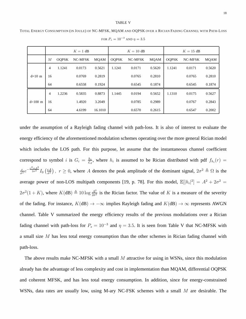
under the assumption of a Rayleigh fading channel with path-loss. It is also of interest to evaluate the
energy efficiency of the aforementioned modulation schemesoperating over the more general Rician model
which includes the LOS path. For this purpose, let assume that the instantaneous channel coefficient
correspond to symboli is Gi = hi
Ld, wherehi is assumed to be Rician distributed with pdffhi
(r) =
rσ2 e
− r2+A2
2σ2 I0(
rAσ2
)
, r ≥ 0, whereA denotes the peak amplitude of the dominant signal,2σ2 , Ω is the
average power of non-LOS multipath components [19, p. 78]. For this model,E[|hi|2] = A2 + 2σ2 =
2σ2(1 +K), whereK(dB) , 10 log A2
2σ2 is the Rician factor. The value ofK is a measure of the severity
of the fading. For instance,K(dB) → −∞ implies Rayleigh fading andK(dB) → ∞ represents AWGN
channel. Table V summarized the energy efficiency results ofthe previous modulations over a Rician
fading channel with path-loss forPs = 10−3 and η = 3.5. It is seen from Table V that NC-MFSK with
a small sizeM has less total energy consumption than the other schemes in Rician fading channel with
path-loss.
The above results make NC-MFSK with a smallM attractive for using in WSNs, since this modulation
already has the advantage of less complexity and cost in implementation than MQAM, differential OQPSK
and coherent MFSK, and has less total energy consumption. Inaddition, since for energy-constrained
WSNs, data rates are usually low, using M-ary NC-FSK schemeswith a smallM are desirable. The

19
0.05 0.1 0.15 0.2 0.25 0.3 0.35 0.4 0.45 0.5 0.5510
−3
10−2
10−1
100
101
Bandwidth Efficiency (bits/s/Hz)
Tot
al E
nerg
y C
onsu
mpt
ion
(Jou
le)
d=10 md=50 md=100 m
M=64
M=2
Fig. 4. Total energy consumption of transmittingN -bit versus bandwidth efficiency for NC-MFSK, and forPs = 10−3 and different values
of d andM .
sacrifice, however, is the bandwidth efficiency of NC-MFSK (when M increases) which is a critical
factor in band-limited WSNs. Since most of WSN applicationsoperate in unlicensed bands where large
bandwidth is available, NC-MFSK can surpass the spectrum constraint in WSNs. To have more insight
into the above discussions for the NC-MFSK, we plot the totalenergy consumption of NC-MFSK as a
function ofBFSeff for different values ofM andd in Fig. 4. In all cases, we observe that the minimumEFS
N
is achieved at low values of distanced and forM = 2, which corresponds to the maximum bandwidth
efficiencyBFSeff = 0.5.
The analysis and numerical evaluations so far implicitly focused on the sinusoidal carrier-based mod-
ulations with the bandwidthB = 62.5 KHz. To complete our analysis, it is of interest to compare the
energy efficiency of the optimized NC-MFSK with the On-Off Keying (OOK), known as the simplest
UWB modulation scheme. For this purpose, we first derive the total energy consumption of OOK with
a similar manner as for sinusoidal carrier-based modulations. Then, we evaluate the energy efficiency
of OOK in terms of distanced. For simplicity of the notation, we use the superscript ‘OK’for OOK
modulation scheme.

20
V. ENERGY CONSUMPTION ANALYSIS OF OOK
For OOK, the number of bits per symbol is defined asb = log2M = 1. An OOK transmitted signal
corresponding to the symbolai ∈ MN is given byxOKi (t) =
√
EOKt aip(t − iTOK
s ), wherep(t) is an
ultra-short pulse of widthTp with unit energy,EOKt is the transmit energy consumption per symbol, and
TOKs is the OOK symbol duration. The ratioTp
TOKs
is defined as theduty-cycle factorof an OOK signal,
which is the fractional on-time of the OOK “1” pulse. The channel bandwidth and the data rate of an
OOK are determined asB ≈ 1Tp
and ROK = 1TOKs
, respectively. As a result, the bandwidth efficiency
of an OOK is obtained asBOKeff , ROK
B= Tp
TOKs
≤ 1 (b/s/Hz) which controls by the duty-cycle factor.
Note that during the transmission of the OOK “0” pulse, the filter and the power amplifier of the OOK
modulator are powered off. During this time, however, the receiver is turned on to detect zero pulses.
For this reason, we still use the same definition for active mode periodTOKac as used for the sinusoidal
carrier-based modulations as follows:
TOKac =
N
bTOKs = NTOK
s . (29)
Depend upon the duty-cycle factor,TOKac can be expressed in terms of bandwidthB. For instance, for an
OOK with the duty-cycle factor Tp
TOKs
= 12, we haveTOK
ac = 2NTp =2NB
, andBOKeff = 1
2. Compared to (4)
for the NC-MFSK, it is concluded thatBOKeff with the duty-cycle factor Tp
TOKs
= 12
is the same as that of
the optimized MFSK (i.e.,M = 2) in Section III. It is shown in [20, pp. 490-504] that the average SER
of an OOK with non-coherent detection is upper bounded by
Ps =1
γOK + 2, (30)
where γOK = ΩLd
EOKt
N0denotes the average received SNR. Thus, the transmit energyconsumption per
symbol is obtained asEOKt , POK
t Tp =(
1Ps
− 2)
LdN0
Ωwhich corresponds to transmitting “1” pulse. An
interesting point is thatEOKt scales the same asEFS
t obtained in (8) for NC-BFSK. This can be easily
proved by using the approximation method in (14)-(16). It should be noted that the energy consumption
of transmittingN-bit during the active mode period, denoted byPOKt
χeTOKac , is equivalent to the energy
consumption of transmittingL-bit “1” in MN , whereL is a binomial random variable with parameters

21
TABLE VI
OOK SYSTEM EVALUATION PARAMETERS
N = 20000 N0 = −180 dB PPG = 675 µw
B = 500 MHz TN = 100 msec PLNA = 3.1 mw
Ml = 40 dB Ttr = 2 nsec PED = 3 mw
L1 = 30 dB PFilt = 2.5 mw PADC = 7 mw
χe = 0.8 PFilr = 2.5 mw PInt = 3 mw
(N, q). Assuming uncorrelated and equally likely binary dataai, we haveq = 12. Hence,P
OKt
χeTOKac =
LχeEOKt = L
(
1Ps
− 2)
LdN0
χeΩ, whereL has the probability mass function PrL = ℓ =
(
N
ℓ
) (
12
)Nwith
E[L] = N2
.
We denote the power consumption of pulse generator, power amplifier and filter asPOKPG , POK
Amp and
POKFilt, respectively. Hence, the circuit energy consumption of the sensor node duringTOK
ac is represented
as a function of the random variableL asPOKct TOK
ac = POKPG TOK
ac +LTp
(
POKFilt + POK
Amp
)
, where the factor
LTp comes from the fact that the filter and the power amplifier are active only during the transmission
of L-bit “1”. We assume thatPOKAmp = αOKPOK
t with αOK = 0.33. In addition, the circuit energy
consumption of the sink node with a non-coherent detection during TOKac is obtained asPOK
cr TOKac =
(
POKLNA + POK
ED + POKFilr + POK
Int + POKADC
)
TOKac , wherePOK
Int is the power consumption of the integrator.
With a similar argument as for the sinusoidal carrier-basedmodulations, we assume that the circuit power
consumption duringTOKtr is governed by the pulse generator. As a result, the total energy consumption of
a non-coherent OOK for transmittingN-bit is obtained as a function of the random variableL as follows:
EOKN (L) = (1 + αOK)L
(
1
Ps
− 2
) LdN0
χeΩ+
1
χe
[
(POKcr + POK
PG )2N
B+
L
BPOK
Filt + 2POKPG TOK
tr
]
, (31)
where we useTOKac = 2N
B. SinceE[L] = N
2, the averageEOK
N (L) is computed as
EOKN , E
[
EOKN (L)
]
= (1 + αOK)
(
1
Ps
− 2
) LdN0
χeΩ
N
2+
1
χe
[
(POKcr + POK
PG )2N
B+
N
2BPOK
Filt + 2POKPG TOK
tr
]
. (32)
It should be noted that the OOK scheme uses the channel bandwidth much wider than that of the

22
sinusoidal carrier-based modulations. Thus, to make a faircomparison with the optimized NC-MFSK, it
is reasonable to use the total energy consumption per information bit defined asEb , ENN
, instead of using
EN . In our comparison, we use the simulation parameters shown in Table VI [13]. Fig. 5 compares the
total energy consumption per information bit of the OOK withthat of the optimized NC-MFSK versus
communication ranged for Ps = 10−3 and different values ofη. We observe that a significant energy
saving is achieved using OOK as compared to the optimized NC-MFSK, whend andη decrease. While,
for the indoor environments whereη is large, the performance difference between OOK and the optimized
NC-MFSK vanishes asd increases. This is because,i) the transmission energy consumption in the active
mode period is dominant whend increases,ii) EOKt scales the same asEFS
t obtained in (8) using (16).
Since, UWB modulation schemes use the channel bandwidth much wider than that of the sinusoidal
carrier-based modulations, the optimized NC-MFSK is desirable in use for the band-limited and sparse
WSNs where the path-loss exponent is large.
VI. CONCLUSION
In this paper, we have analyzed the energy efficiency of some popular modulation schemes to find the
distance-based green modulations in a WSN over Rayleigh andRician flat-fading channels with path-loss.
It was demonstrated that among various sinusoidal carrier-based modulations, the optimized NC-MFSK
is the most energy-efficient scheme in sparse WSNs for each value of the path-loss exponent, where the
optimization is performed over the modulation parameters.In addition, NC-MFSK with a smallM is
attractive for using in WSNs, since this modulation alreadyhas the advantage of less complexity and
cost in implementation than MQAM, differential OQPSK and coherent MFSK, and has less total energy
consumption. Furthermore, MFSK has a faster start-up time than other schemes. Moreover, since for
energy-constrained WSNs, data rates are usually low, usingM-ary NC-FSK schemes with a smallM
are desirable. The sacrifice, however, is the bandwidth efficiency of NC-MFSK whenM increases. Since
most of WSN applications requires low to moderate bandwidth, a loss in the bandwidth efficiency can
be tolerable, in particular for the unlicensed band applications where large bandwidth is available. It also

23
0 20 40 60 80 10010
−10
10−9
10−8
10−7
10−6
10−5
d (m)
Ene
rgy
Per
Bit
(Jou
le)
η=2.5
0 20 40 60 80 10010
−10
10−8
10−6
10−4
10−2
d (m)
Ene
rgy
Per
Bit
(Jou
le)
η=3.5
0 20 40 60 80 10010
−10
10−8
10−6
10−4
10−2
100
d (m)
Ene
rgy
Per
Bit
(Jou
le)
η=4.5
0 20 40 60 80 10010
−10
10−5
100
105
d (m)
Ene
rgy
Per
Bit
(Jou
le)
η=5.5
NC−MFSKOOK
NC−MFSKOOK
NC−MFSKOOK
NC−MFSKOOK
Fig. 5. Total energy consumption per information bit versusd for OOK and the optimized NC-MFSK, and forPs = 10−3.
found that OOK has a significant energy saving as compared to the optimized NC-MFSK in dense WSNs
with small values of path-loss exponent. While, for the indoor environments where the path-loss exponent
is large, the performance difference between OOK and the optimized NC-MFSK vanishes as the distance
between the sensor and sink nodes increases. In this case, the optimized NC-MFSK is attractive in use
for the band-limited and sparse indoor WSNs.
REFERENCES
[1] Abouei, J., Plataniotis, K. N., and Pasupathy, S.: ‘Green modulation in dense wireless sensor networks,’Proc. of IEEE International
Conference on Acoustics, Speech and Signal Processing (ICASSP’10), Dallas, Texas, USA, March 2010, pp. 3382–3385.
[2] Abouei, J., Brown, J. D., Plataniotis, K. N., and Pasupathy, S.: ‘On the energy efficiency of LT codes in proactive wireless sensor
networks,’ Proc. of IEEE Biennial Symposium on Communications (QBSC’10), Queen’s University, Kingston, Canada, May 2010, pp.
114–117.

24
[3] Qu, F., Duan, D., Yang, L., and Swami, A.: ‘Signaling withimperfect channel state information: A battery power efficiency comparison,’
IEEE Trans. on Signal Processing, vol. 56, no. 9, Sep. 2008, pp. 4486–4495.
[4] Garzs, J. E., Calzn, C. B., and Armada, A. G.: ‘An energy-efficient adaptive modulation suitable for wireless sensor networks with
SER and throughput constraints,’EURASIP Journal on Wireless Communications and Networking, vol. 2007, no. 1, Jan. 2007.
[5] Cui, S., Goldsmith, A. J., and Bahai, A.: ‘Energy-constrained modulation optimization,’IEEE Trans. on Wireless Commun., vol. 4,
no. 5, Sept. 2005, pp. 2349–2360.
[6] IEEE Standards, ‘Part 15.4: Wireless Medium Access control (MAC) and Physical Layer (PHY) Specifications for Low-Rate Wireless
Personal Area Networks (WPANs),’ inIEEE 802.15.4 Standards, Sept. 2006.
[7] Mingoo, S., Hanson, S., Sylvester, D., and Blaauw, D., ‘Analysis and optimization of sleep modes in subthreshold circuit design,’ in
Proc. 44th ACM/IEEE Design Automation Conference, San Diego, California, June 2007, pp. 694–699.
[8] Karl, H., and Willig, A.: Protocols and Architectures for Wireless Sensor Networks, John Wiley and Sons Inc., first edition, 2005.
[9] Tanchotikul, S., Supanakoon, P., Promwong, S., and Takada, J.: ‘Statistical model RMS delay spread in UWB ground reflection channel
based on peak power loss,’ inProc. of ISCIT’06, 2006, pp. 619–622.
[10] Proakis, J. G.:Digital Communications, New York: McGraw-Hill, forth edition, 2001.
[11] Hind Chebboet al., ‘Proposal for Partial PHY and MAC including Emergency Management in IEEE802.15.6,’ May 2009, available
at IEEE 802.15 WPAN TG6 in Body Area Network (BAN), http://www.ieee802.org/15/pub/TG6.html.
[12] Xiong, F.: Digital Modulation Techniques, Artech House, Inc., second edition, 2006.
[13] Abouei, J., Plataniotis, K. N., and Pasupathy, S.: ‘Green modulation in proactive wireless sensor networks,’ Technical report, University
of Toronto, ECE Dept., Sept. 2009, available at http://www.dsp.utoronto.ca/∼abouei/.
[14] Tang, Q., Yang, L., Giannakis, G. B., and Qin, T.: ‘Battery power efficiency of PPM and FSK in wireless sensor networks,’ IEEE
Trans. on Wireless Commun., vol. 6, no. 4, April 2007, pp. 1308–1319.
[15] Ziemer, R. E., and Peterson, R. L.:Digital Communications and Spread Spectrum Systems, New York: Macmillman, 1985.
[16] Simon, M. K., and Alouini, M.-S.:Digital Communication over Fading Channels, New York: Wiley Interscience, second edition,
2005.
[17] Simon, M.-S.: ‘Multiple-bit differential detection of offset QPSK,’ IEEE Trans. on Commun., vol. 51, pp. 1004–1011, June 2003.
[18] ‘Range extension for IEEE 802.15.4 and ZigBee applications,’ FreeScale Semiconductor, Application Note, Feb. 2007.
[19] Goldsmith, A.: Wireless Communications, Cambridge University Press, first edition, 2005.
[20] Couch, L. W.:Digital and Analog Communication Systems, Prentice-Hall, sixth edition, 2001.
Recommended