1
FINITE STATE MACHINES - II STATE MINIMIZATION
PARTITIONING MINIMIZATION PROCEDURE VENDING MACHINE EXAMPLE
ANALYSIS OF SYNCHRONOUS SEQUENTIAL CIRCUITS
PROCEDURE EXAMPLE
ALGORITHMIC STATE MACHINES (ASM) CHARTS COMPLETE FSM DESIGN EXAMPLE
PARALLEL-TO-SERIAL CONVERTER WITH PARITY GENERATOR__________________________________________________
ECSE-323/Department of Electrical and Computer Engineering/McGill University/ Prof. Marin.Figures taken from Fundamentals of Digital Logic with VHDL Design, S. Brown and Z. Vranesic, 2nd Edition, McGraw Hill.
2
FINITE STATE MACHINES - II STATE MINIMIZATION
PARTITIONING MINIMIZATION PROCEDURE
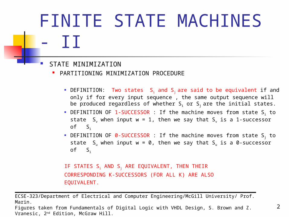
DEFINITION: Two states Si and Sj are said to be equivalent if and only if for every input sequence , the same output sequence will be produced regardless of whether Si or Sj are the initial states.
DEFINITION OF 1-SUCCESSOR : If the machine moves from state Si to state Sv when input w = 1, then we say that Sv is a 1-successor of Si
DEFINITION OF 0-SUCCESSOR : If the machine moves from state Sj to state Su when input w = 0, then we say that Su is a 0-successor of Si
IF STATES Si AND Sj ARE EQUIVALENT, THEN THEIR
CORRESPONDING K-SUCCESSORS (FOR ALL K) ARE ALSOEQUIVALENT.
__________________________________________________ECSE-323/Department of Electrical and Computer Engineering/McGill University/ Prof. Marin.Figures taken from Fundamentals of Digital Logic with VHDL Design, S. Brown and Z. Vranesic, 2nd Edition, McGraw Hill.

3
FINITE STATE MACHINES - II STATE MINIMIZATION
PARTITIONING MINIMIZATION PROCEDURE (CONTINUES)
DEFINITION: A PARTITION CONSISTS OF ONE OR MORE BLOCKS, WHERE EACH BLOCK COMPRISES A SUBSET OF STATES THAT MAY BE EQUIVALENT, BUT THE STATES IN A GIVEN BLOCK ARE DEFINITELY NOT EQUVALENT TO THE STATES IN THE OTHER BLOCK.
__________________________________________________ECSE-323/Department of Electrical and Computer Engineering/McGill University/ Prof. Marin.Figures taken from Fundamentals of Digital Logic with VHDL Design, S. Brown and Z. Vranesic, 2nd Edition, McGraw Hill.
4
FINITE STATE MACHINES - II STATE MINIMIZATION
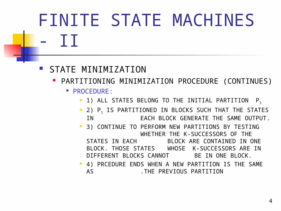
PARTITIONING MINIMIZATION PROCEDURE (CONTINUES)
PROCEDURE: 1) ALL STATES BELONG TO THE INITIAL PARTITION P1 2) P1 IS PARTITIONED IN BLOCKS SUCH THAT THE STATES IN
EACH BLOCK GENERATE THE SAME OUTPUT.
3) CONTINUE TO PERFORM NEW PARTITIONS BY TESTING WHETHER THE K-SUCCESSORS OF THE
STATES IN EACH BLOCK ARE CONTAINED IN ONE BLOCK. THOSE STATES WHOSE K-SUCCESSORS ARE IN DIFFERENT BLOCKS CANNOT BE IN ONE BLOCK.
4) PRCEDURE ENDS WHEN A NEW PARTITION IS THE SAME AS .THE PREVIOUS PARTITION

5
FINITE STATE MACHINES - II STATE MINIMIZATION
PARTITIONING MINIMIZATION PROCEDURE (CONTINUES) EXAMPLE: Consider the following state transition table
P1 = (ABCDEFG)
P2 = (ABD)(CEFG) Diff. Outputs.
Because (CEFG) 0-successors are (FFEF) in same block,
(CEFG) 1-successors are (ECDG) in diff. block,
F must be different from C, E and G
P3 = (ABD)(CEG)(F)P4 = (AD)(B)(CEG)(F)
Same process for (AD) and (CEG) gives
P5 = (AD)(B)(CEG)(F)P5 = P4
Present Next state Outputstate w = 0 w = 1 z
A B C 1 B D F 1 C F E 0 D B G 1 E F C 0 F E D 0 G F G 0

6
FINITE STATE MACHINES - II STATE MINIMIZATION
PARTITIONING MINIMIZATION PROCEDURE (CONTINUES)
EXAMPLE (CONTINUES): MINIMAL STATE TRAMSITION TABLE
ORIGINAL TABLE P4 = (AD)(B)(CEG)(F)
MINIMIZED TABLE
Present Next state Outputstate w = 0 w = 1 z
A B C 1 B D F 1 C F E 0 D B G 1 E F C 0 F E D 0 G F G 0
Present Nextstate Outputstate w = 0 w = 1 z
A B C 1 B A F 1 C F C 0 F C A 0

7
FINITE STATE MACHINES - II STATE MINIMIZATION
VENDING MACHINE EXAMPLE
Design an FSM that will dispense candy under the followingconditions:
1.- The machine accepts nickels and dimes 2.- 15 cents releases a candy from the
machine 3.- If 20 cents is deposited, the machine will
not return the change, but it credit the buyer with 5 cents and wait for the buyer to make a second purchase __________________________________________________
ECSE-323/Department of Electrical and Computer Engineering/McGill University/ Prof. Marin.Figures taken from Fundamentals of Digital Logic with VHDL Design, S. Brown and Z. Vranesic, 2nd Edition, McGraw Hill.
8
FINITE STATE MACHINES - II STATE MINIMIZATION
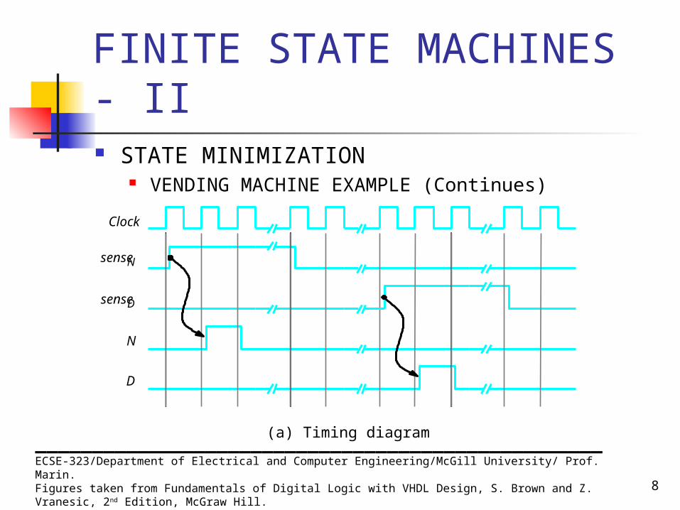
VENDING MACHINE EXAMPLE (Continues)
__________________________________________________ECSE-323/Department of Electrical and Computer Engineering/McGill University/ Prof. Marin.Figures taken from Fundamentals of Digital Logic with VHDL Design, S. Brown and Z. Vranesic, 2nd Edition, McGraw Hill.
sense N
sense D
Clock
N
D
(a) Timing diagram
9
FINITE STATE MACHINES - II STATE MINIMIZATION
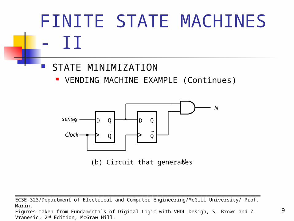
VENDING MACHINE EXAMPLE (Continues)
__________________________________________________ECSE-323/Department of Electrical and Computer Engineering/McGill University/ Prof. Marin.Figures taken from Fundamentals of Digital Logic with VHDL Design, S. Brown and Z. Vranesic, 2nd Edition, McGraw Hill.
D Q
Q
sense N D Q
Q Clock
N
(b) Circuit that generates N
10
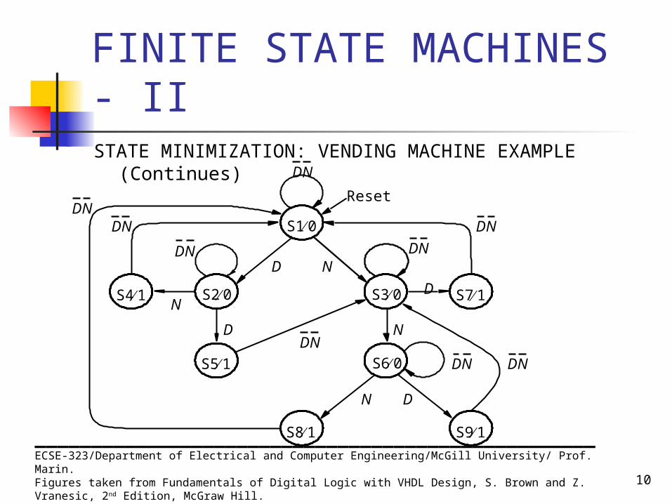
FINITE STATE MACHINES - IISTATE MINIMIZATION: VENDING MACHINE EXAMPLE
(Continues)
__________________________________________________ECSE-323/Department of Electrical and Computer Engineering/McGill University/ Prof. Marin.Figures taken from Fundamentals of Digital Logic with VHDL Design, S. Brown and Z. Vranesic, 2nd Edition, McGraw Hill.
S1 0
S7 1
DN
D N
S3 0
S6 0
S9 1 S8 1
S2 0
S5 1
S4 1
DNDN
DNDNDN
DNDN
D
D N
D N
DN
N
Reset

11
FINITE STATE MACHINES - II STATE MINIMIZATION
VENDING MACHINE EXAMPLE (Continues)
P1 = (S1, S2, S3, S4, S5, S6, S7, S8, S9)
P2 = (S1, S2, S3, S6)(S4, S5, S7, S8, S9)
P3 = (S1)(S3)(S2, S6)(S4, S5, S7, S8, S9)
P4 = (S1)(S3)(S2, S6)(S4, S7, S8)(S5,S9)
P5 = (S1)(S3)(S2, S6)(S4, S7, S8)(S5,S9)
__________________________________________________ECSE-323/Department of Electrical and Computer Engineering/McGill University/ Prof. Marin.Figures taken from Fundamentals of Digital Logic with VHDL Design, S. Brown and Z. Vranesic, 2nd Edition, McGraw Hill.
Present Next state Outputstate DN =00 01 10 11 z
S1 S1 S3 S2 0 S2 S2 S4 S5 0 S3 S3 S6 S7 0 S4 S1 1 S5 S3 1 S6 S6 S8 S9 0 S7 S1 1 S8 S1 1 S9 S3 1
––
–––
––
–––
–––––––––
12
FINITE STATE MACHINES - II
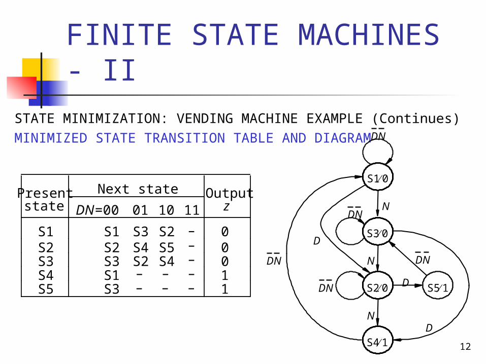
STATE MINIMIZATION: VENDING MACHINE EXAMPLE (Continues)MINIMIZED STATE TRANSITION TABLE AND DIAGRAM
Present Next state Outputstate DN =00 01 10 11 z
S1 S1 S3 S2 0 S2 S2 S4 S5 0 S3 S3 S2 S4 0 S4 S1 1 S5 S3 1
–––
– – –– – –
S1 0
S5 1
DNDN
DN
DN
DN
D
D
D
N
N
N
S3 0
S20
S4 1

13
FINITE STATE MACHINES - II
STATE MINIMIZATION: VENDING MACHINE EXAMPLE (Continues)
MINIMIZED STATE TRANSITION DIAGRAM: Moore-type versus Mealy-type
MOORE-TYPE MEALY_TYPE
S1 0
S5 1
DNDN
DN
DN
DN
D
D
D
N
N
N
S3 0
S20
S4 1
S3
S2
D 0
S1
D 1
D 1
N 1
N 0
N 0 DN0
DN0
DN0
14
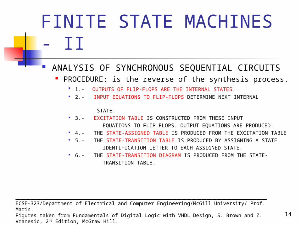
FINITE STATE MACHINES - II ANALYSIS OF SYNCHRONOUS SEQUENTIAL
CIRCUITS PROCEDURE: is the reverse of the synthesis process.
1.- OUTPUTS OF FLIP-FLOPS ARE THE INTERNAL STATES. 2.- INPUT EQUATIONS TO FLIP-FLOPS DETERMINE NEXT INTERNAL
STATE.
3.- EXCITATION TABLE IS CONSTRUCTED FROM THESE INPUT
EQUATIONS TO FLIP-FLOPS. OUTPUT EQUATIONS ARE PRODUCED. 4.- THE STATE-ASSIGNED TABLE IS PRODUCED FROM THE EXCITATION
TABLE 5.- THE STATE-TRANSITION TABLE IS PRODUCED BY ASSIGNING A STATE IDENTIFICATION LETTER TO EACH ASSIGNED STATE. 6.- THE STATE-TRANSITION DIAGRAM IS PRODUCED FROM THE STATE- TRANSITION TABLE.__________________________________________________
ECSE-323/Department of Electrical and Computer Engineering/McGill University/ Prof. Marin.Figures taken from Fundamentals of Digital Logic with VHDL Design, S. Brown and Z. Vranesic, 2nd Edition, McGraw Hill.

15
FINITE STATE MACHINES - II ANALYSIS OF SYNCHRONOUS SEQUENTIAL CIRCUITS
EXAMPLE: ANALYZE THE FOLLOWING CIRCUIT
Exitation equations: DY1 = w !y1
+ w y2
DY2 = w y1 + w y2
z = y1 y2
Next state equations: Y1 = DY1 = w !y1 + w y2
Y2 = DY2 = w y1 + w y2
__________________________________________________ECSE-323/Department of Electrical and Computer Engineering/McGill University/ Prof. Marin.Figures taken from Fundamentals of Digital Logic with VHDL Design, S. Brown and Z. Vranesic, 2nd Edition, McGraw Hill.
D Q
Q
D Q
Q
Clock
Resetn
y 2
y 1
Y 2
Y 1
w
z
16
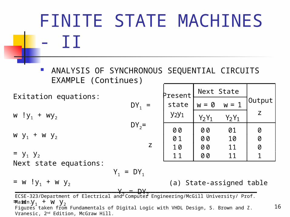
FINITE STATE MACHINES - II ANALYSIS OF SYNCHRONOUS SEQUENTIAL CIRCUITS
EXAMPLE (Continues)
__________________________________________________ECSE-323/Department of Electrical and Computer Engineering/McGill University/ Prof. Marin.Figures taken from Fundamentals of Digital Logic with VHDL Design, S. Brown and Z. Vranesic, 2nd Edition, McGraw Hill.
Present Next State
state w = 0 w = 1 Output
y 2 y 1 Y 2 Y 1 Y 2 Y 1 z
0 0 0 0 01 0 0 1 0 0 10 0 1 0 0 0 11 0 1 1 0 0 11 1
(a) State-assigned table
Exitation equations: DY1 = w !y1 + wy2
DY2= w y1 + w y2 z = y1 y2
Next state equations: Y1 = DY1 = w !y1 + w y2
Y2 = DY2 = w y1 + w y2
17
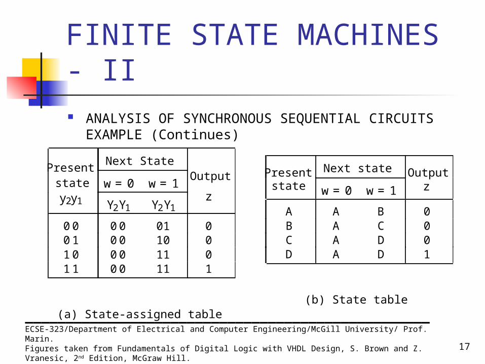
FINITE STATE MACHINES - II ANALYSIS OF SYNCHRONOUS SEQUENTIAL CIRCUITS
EXAMPLE (Continues)
__________________________________________________ECSE-323/Department of Electrical and Computer Engineering/McGill University/ Prof. Marin.Figures taken from Fundamentals of Digital Logic with VHDL Design, S. Brown and Z. Vranesic, 2nd Edition, McGraw Hill.
Present Next State
state w = 0 w = 1 Output
y 2 y 1 Y 2 Y 1 Y 2 Y 1 z
0 0 0 0 01 0 0 1 0 0 10 0 1 0 0 0 11 0 1 1 0 0 11 1
(a) State-assigned table
Present Next state Outputstate w = 0 w = 1 z
A A B 0 B A C 0 C A D 0 D A D 1
(b) State table
18
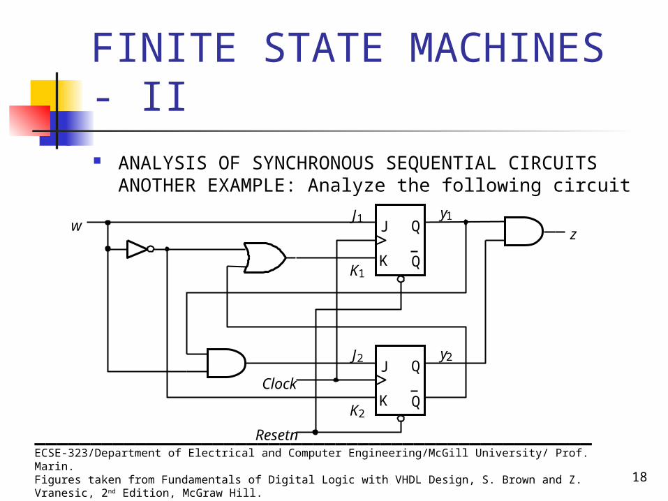
FINITE STATE MACHINES - II ANALYSIS OF SYNCHRONOUS SEQUENTIAL CIRCUITS
ANOTHER EXAMPLE: Analyze the following circuit
__________________________________________________ECSE-323/Department of Electrical and Computer Engineering/McGill University/ Prof. Marin.Figures taken from Fundamentals of Digital Logic with VHDL Design, S. Brown and Z. Vranesic, 2nd Edition, McGraw Hill.
J Q
Q
Clock
Resetn
y2
y1
J2
J1wz
K
J Q
QKK2
K1

19
FINITE STATE MACHINES - II ANALYSIS OF SYNCHRONOUS SEQUENTIAL CIRCUITS
ANOTHER EXAMPLE (Continues)
Excitation Equations J1 = w
K1 = !w + !y2
J2 = w y1
K2 = !w
z = y1 y2
__________________________________________________
ECSE-323/Department of Electrical and Computer Engineering/McGill University/ Prof. Marin.Figures taken from Fundamentals of Digital Logic with VHDL Design, S. Brown and Z. Vranesic, 2nd Edition, McGraw Hill.
J Q
Q
Clock
Resetn
y2
y1
J2
J1wz
K
J Q
QKK2
K1

20
FINITE STATE MACHINES - II ANALYSIS OF SYNCHRONOUS SEQUENTIAL CIRCUITS
ANOTHER EXAMPLE (Continues)
Excitation EquationsJ1 = w
K1 = !w + !y2
J2 = w y1
K2 = !w
z = y1 y2
__________________________________________________ECSE-323/Department of Electrical and Computer Engineering/McGill University/ Prof. Marin.Figures taken from Fundamentals of Digital Logic with VHDL Design, S. Brown and Z. Vranesic, 2nd Edition, McGraw Hill.
Present Flip-flop inputs
state w = 0 w = 1 Output
y 2 y 1 J 2 K 2 J 1 K 1 J 2 K 2 J 1 K 1 z
00 01 0 1 0 0 1 1 0 01 01 0 1 1 0 1 1 0 10 01 0 1 0 0 1 0 0 11 01 0 1 1 0 1 0 1

21
FINITE STATE MACHINES - II
ANALYSIS OF SYNCHRONOUS SEQUENTIAL CIRCUITS ANOTHER EXAMPLE (Continues)
EXCITATION TABLE STATE-ASSIGNED TABLE
__________________________________________________ECSE-323/Department of Electrical and Computer Engineering/McGill University/ Prof. Marin.Figures taken from Fundamentals of Digital Logic with VHDL Design, S. Brown and Z. Vranesic, 2nd Edition, McGraw Hill.
Present Flip-flop inputs
state w = 0 w = 1 Output
y 2 y 1 J 2 K 2 J 1 K 1 J 2 K 2 J 1 K 1 z
00 01 0 1 0 0 1 1 0 01 01 0 1 1 0 1 1 0 10 01 0 1 0 0 1 0 0 11 01 0 1 1 0 1 0 1
Present Next State
state w = 0 w = 1 Output
y 2 y 1 Y 2 Y 1 Y 2 Y 1 z
0 0 0 0 01 0 0 1 0 0 10 0 1 0 0 0 11 0 1 1 0 0 11 1

22
FINITE STATE MACHINES - II ANALYSIS OF SYNCHRONOUS SEQUENTIAL CIRCUITS
EXAMPLE (Continues)
__________________________________________________ECSE-323/Department of Electrical and Computer Engineering/McGill University/ Prof. Marin.Figures taken from Fundamentals of Digital Logic with VHDL Design, S. Brown and Z. Vranesic, 2nd Edition, McGraw Hill.
Present Next State
state w = 0 w = 1 Output
y 2 y 1 Y 2 Y 1 Y 2 Y 1 z
0 0 0 0 01 0 0 1 0 0 10 0 1 0 0 0 11 0 1 1 0 0 11 1
(a) State-assigned table
Present Next state Outputstate w = 0 w = 1 z
A A B 0 B A C 0 C A D 0 D A D 1
(b) State table
23
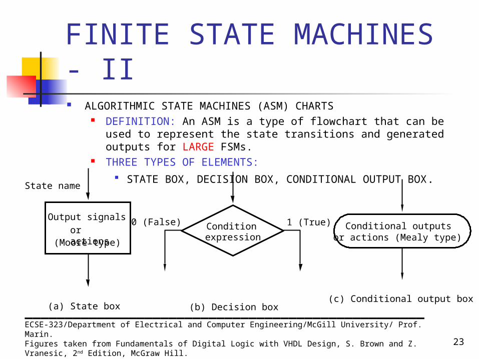
FINITE STATE MACHINES - II ALGORITHMIC STATE MACHINES (ASM) CHARTS
DEFINITION: An ASM is a type of flowchart that can be used to represent the state transitions and generated outputs for LARGE FSMs.
THREE TYPES OF ELEMENTS: STATE BOX, DECISION BOX, CONDITIONAL OUTPUT BOX.
__________________________________________________ECSE-323/Department of Electrical and Computer Engineering/McGill University/ Prof. Marin.Figures taken from Fundamentals of Digital Logic with VHDL Design, S. Brown and Z. Vranesic, 2nd Edition, McGraw Hill.
Output signals
or actions(Moore type)
State name
(a) State box
Condition expression
0 (False) 1 (True)
(b) Decision box
Conditional outputs or actions (Mealy type)
(c) Conditional output box
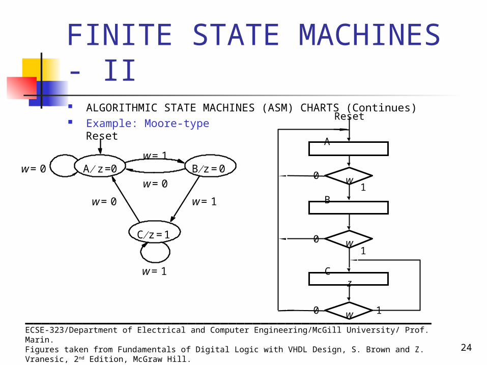
24
FINITE STATE MACHINES - II ALGORITHMIC STATE MACHINES (ASM) CHARTS (Continues) Example: Moore-type
__________________________________________________ECSE-323/Department of Electrical and Computer Engineering/McGill University/ Prof. Marin.Figures taken from Fundamentals of Digital Logic with VHDL Design, S. Brown and Z. Vranesic, 2nd Edition, McGraw Hill.
C z 1 =
Reset
B z 0 = A z 0 = w 0 =
w 1 =
w 1 =
w 0 =
w 0 = w 1 =
w
w
w 0 1
0 1
0 1
A
B
C z
Reset
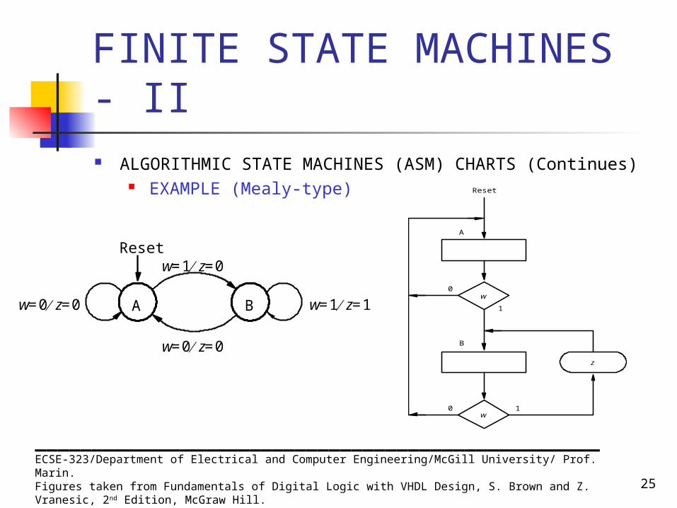
25
FINITE STATE MACHINES - II ALGORITHMIC STATE MACHINES (ASM) CHARTS (Continues)
EXAMPLE (Mealy-type)
__________________________________________________ECSE-323/Department of Electrical and Computer Engineering/McGill University/ Prof. Marin.Figures taken from Fundamentals of Digital Logic with VHDL Design, S. Brown and Z. Vranesic, 2nd Edition, McGraw Hill.
w
w 0 1
0
1
A
B
Reset
z
A
w 0 = z 0 =
w 1 = z 1 = B w 0 = z 0 =
Reset w 1 = z 0 =
26
FINITE STATE MACHINES - II
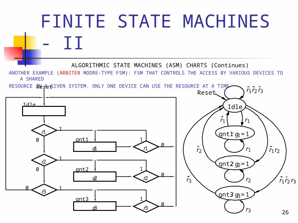
ALGORITHMIC STATE MACHINES (ASM) CHARTS (Continues)ANOTHER EXAMPLE (ARBITER MOORE-TYPE FSM): FSM THAT CONTROLS THE ACCESS BY VARIOUS DEVICES TO
A SHAREDRESOURCE IN A GIVEN SYSTEM. ONLY ONE DEVICE CAN USE THE RESOURCE AT A TIME.
r 1
r 3 0 1
1
Idle
Reset
r 2
r 1
r 3
r 2
gnt1
gnt2
gnt3
1
1
1
0
0
0
g 1
g 2
g 3
0
0
1
r 1 r 2
r 1 r 2 r 3
Idle
Reset
gnt1 g 1 1 =
gnt2 g 2 1 =
gnt3 g 3 1 =
r 1 r 1
r 1
r 2
r 3
r 2
r 3
r 1 r 2 r 3
27
FINITE STATE MACHINES - II COMPLETE FSM DESIGN EXAMPLE
PARALLEL-TO-SERIAL CONVERTER WITH PARITY GENERATOR
Word description
Design a digital systems that will convert an 8-bit parallel message, (b7 , b6 , b5 , b4 , b3 , b2 , b1 , b0), composed of 7-bit ASCII character plus an initially set to 0 parity bit, into an 8-bit serial message with the correct parity bit set into bit b7 .
__________________________________________________ECSE-323/Department of Electrical and Computer Engineering/McGill University/ Prof. Marin.Figures taken from Fundamentals of Digital Logic with VHDL Design, S. Brown and Z. Vranesic, 2nd Edition, McGraw Hill.

28
FINITE STATE MACHINES - II
COMPLETE FSM DESIGN EXAMPLEPARALLEL-TO-SERIAL CONVERTER WITH PARITY GENERATOR BLOCK DIAGRAM (Data Path and Control Unit)
__________________________________________________ECSE-323/Department of Electrical and Computer Engineering/McGill University/ Prof. Marin.Figures taken from Fundamentals of Digital Logic with VHDL Design, S. Brown and Z. Vranesic, 2nd Edition, McGraw Hill.

29
FINITE STATE MACHINES - II
COMPLETE FSM DESIGN EXAMPLEPARALLEL-TO-SERIAL CONVERTER WITH PARITY GENERATOR STATE TRANSITION TABLE
__________________________________________________ECSE-323/Department of Electrical and Computer Engineering/McGill University/ Prof. Marin.Figures taken from Fundamentals of Digital Logic with VHDL Design, S. Brown and Z. Vranesic, 2nd Edition, McGraw Hill.

30
FINITE STATE MACHINES - II
COMPLETE FSM DESIGN EXAMPLEPARALLEL-TO-SERIAL CONVERTER WITH PARITY GENERATOR STATE-ASSIGNED TABLE
CHOICE OF FLIP-FLOPS AND EXCITATION EQUATIONDy = Y = w y
__________________________________________________ECSE-323/Department of Electrical and Computer Engineering/McGill University/ Prof. Marin.Figures taken from Fundamentals of Digital Logic with VHDL Design, S. Brown and Z. Vranesic, 2nd Edition, McGraw Hill.
31
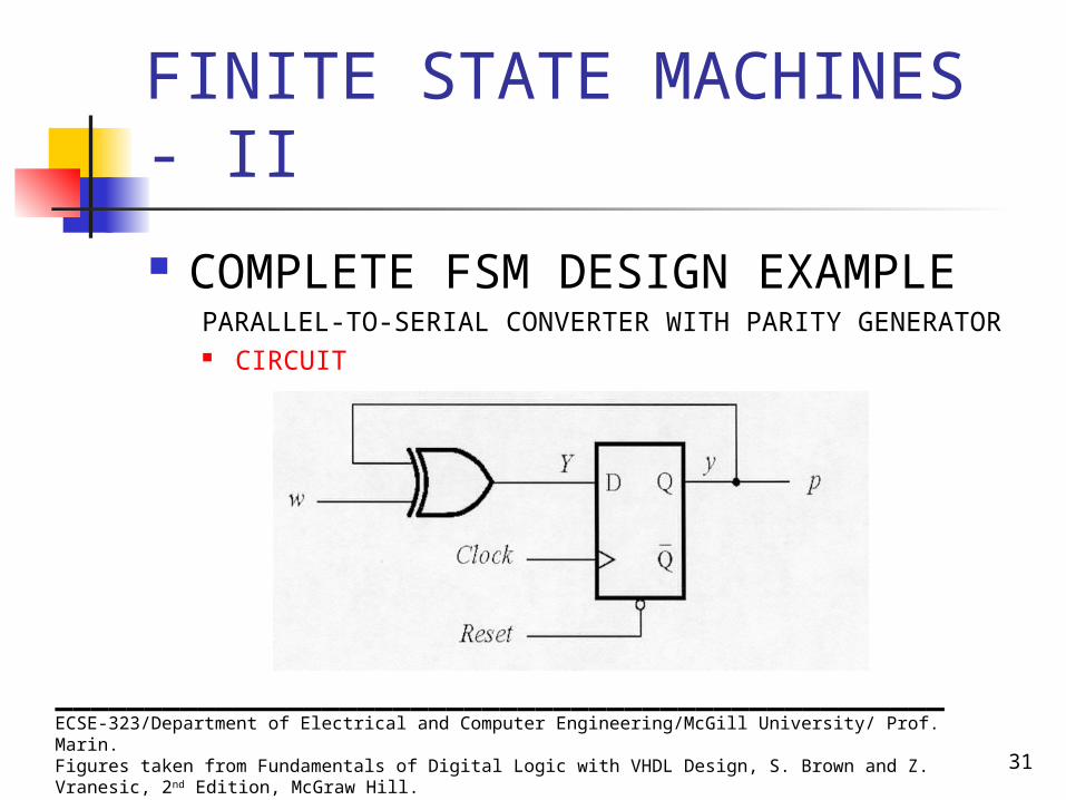
FINITE STATE MACHINES - II
COMPLETE FSM DESIGN EXAMPLEPARALLEL-TO-SERIAL CONVERTER WITH PARITY GENERATOR CIRCUIT
__________________________________________________ECSE-323/Department of Electrical and Computer Engineering/McGill University/ Prof. Marin.Figures taken from Fundamentals of Digital Logic with VHDL Design, S. Brown and Z. Vranesic, 2nd Edition, McGraw Hill.
Recommended