Company Profile
Established: September 11th 1978
Capital: USD 32 million
Revenue: USD 59 million
Employees: 900
Listing: August 29th 1998, Taiwan Stock Exchange
Stock Code: 2375
Product Lines: Aluminum Electrolytic Capacitor
Conductive Polymer Solid Aluminum Capacitor
Milestones: 1956 Set-up Aluminum Capacitor Division at SAMPO Electronic
1975 First development and mass production at Low ESR product in Taiwan
1978 Foundation of Teapo Electronic Capacitor
1998 Company stock listed in OTC market in Taiwan
1998 Manufacturing plant in Dongguan ,China
2001 Dongguan factory certified by ISO9001:2000
2005 Merge G-LUXON Electronic Corporation
2006 Manufacturing polymer capacitors
2008 Dongguan factory certified by ISO9001:2008
2010 Dongguan factory certified by ISO14001:2004
2014 Dongguan factory certified by ISO/TS16949:2009
2014 Dongguan factory certified by IECQ/QC08000:2012
1
2
3
4
CONDUCTIVE POLYMER ALUMINUM SOLID CAPACITORS-----------25
LARGE ALUMINUM ELECTROLYTIC CAPACITORS-----------------144
MINIATURE ALUMINUM ELECTROLYTIC CAPACITORS-------------79
SURFACE MOUNT ALUMINUM ELECTROLYTIC CAPACITORS----53
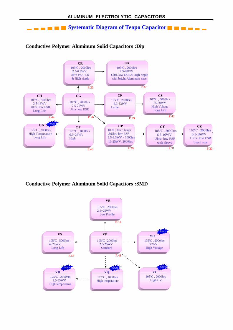
ALUMINUM ELECTROLYTIC CAPACITORS
▂ ▃ ▄ ▅ ▆ ▇ Systematic Diagram of Teapo Capacitor▇ ▆ ▅ ▄ ▃ ▂
Conductive Polymer Aluminum Solid Capacitors :Dip
CP105ºC, 8mm heigh &Ultra low ESR 2.5-6.3WV,3000hrs 10-25WV, 2000hrs
CG
105ºC , 2000hrs2.5-25WV
Ultra low ESR
CF105ºC , 2000hrs
6.3-63WVLarge
CX105ºC , 2000hrs
2.5-28WVUltra low ESR & High ripplewith bright Aluminum case
CY105ºC , 2000hrs
6.3-16WVUltra low ESR
with sleeve
CR105ºC , 2000hrs
2.5-6.3WVUltra low ESR& High ripple
CS105ºC , 5000hrs
25-50WVHigh Voltage
Long Life
CH105ºC , 5000hrs
2.5-16WVUltra low ESR
Long Life
CZ105ºC , 2000hrs
6.3-16WV Ultra low ESR
Small size
CT125ºC , 1000hrs6.3~25WVHigh
CA125ºC , 2000hrs
High Temperature Long Life
Conductive Polymer Aluminum Solid Capacitors :SMD
VP
105ºC , 2000hrs2.5-25WV
Standard
VB
105ºC , 2000hrs2.5~25WV
Low Profile
VD105ºC , 2000hrs
35WVHigh Voltage
VC105ºC , 2000hrs
High CV
VQ125ºC , 1000hrsHigh temperature
VS
105ºC , 5000hrs4~20WV
Long Life
VR125ºC , 2000hrs
2.5-35WVHigh temperature
futurefuturefuture
future
future
P.35 P.37
P.44 P.26 P.39 P.42
P.46 P.29 P.31 P.33
P.51
P.48P.53

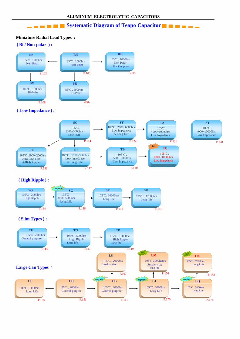
ALUMINUM ELECTROLYTIC CAPACITORS
▂ ▃ ▄ ▅ ▆ ▇ Systematic Diagram of Teapo Capacitor▇ ▆ ▅ ▄ ▃ ▂
XV 105ºC , 3000~5000hrsUltra Low Impedance
Long Life
FV 85ºC
3000~5000hrsLong Life
DV
105ºC , 2000hrsLong Life
SV 105ºC , 1000hrs
Low Profile
ZV 105ºC , 1000hrs
Low Impedance
GV
85ºC , 2000hrsLow Profile
CV 85ºC , 2000hrs
Low leakage current
EV 105ºC , 2000hrs
Ultra Low Impedance
NV
105ºC , 2000hrsNon-Polar
HV 125ºC , 2000hrsUltra Low Impedance
High temperature
JV105ºC , 2000hrsLow profile ,
Ultra low
Chip Types :
Miniature Radial Lead
SE
105ºC , 1000hrsGeneral purpose
SK 85ºC , 2000hrs
General purpose
SH
105ºC , 2000hrsGeneral purpose
( General Purpose ) :
( Low Profile ) :
D7
85ºC , 1000hrs7 / 9mm heihgt
D5
85ºC , 1000hrs5mm height
S5
105ºC , 1000hrs5mm height
H5
105ºC , 2000hrs5mm height
S7 105ºC , 1000hrs7 / 9mm heihgt
H7
105ºC , 2000hrs7 / 9mm height
YV105ºC , 1000~2000hrsLow Impedance
( Low Leakage Current ) :
SB 105ºC , 1000hrs
Low LeakageCurrent
AK125ºC ,
2000~5000hrsHigh Temperature
(High Temperature ) :
P.65 P.73
P.71P.67P.63P.59P.61
P.77
105ºC , 2000hrsNon-Polar
P.55 P.75 P.69
P.57
P.85P.82P.79
P.92P.90P.88
P.94 P.96 P.98
P.110 P.132
TE105℃,6000~10000Hrs
LED Lighting Ultra Long Life
P.143
new
(LED Lighting ) :
ALUMINUM ELECTROLYTIC CAPACITORS
▂ ▃ ▄ ▅ ▆ ▇ Systematic Diagram of Teapo Capacitor▇ ▆ ▅ ▄ ▃ ▂
Miniature Radial Lead Types :
( Low Impedance ) :
SY 105ºC , 2000~6000hrs
Low Impedance& Long Life
SJ
Large Can Types :
LH
85ºC , 2000hrsGeneral purpose
LF
85ºC , 3000hrsLong Life
LG
105ºC , 2000hrsGeneral purpose
LJ
105ºC , 3000hrsLong Life
SN 105ºC , 1000hrs
Non-Polar
BX
105ºC , 1000hrsBi-Polar
RN
85ºC , 1000hrsNon-Polar
SR
85ºC , 1000hrsBi-Polar
RB 85ºC , 1000hrs
Non-PolarFor Coupling
( Bi / Non-polar ) :
105ºC , 5000hrsLong Life
( Slim Types ) :
SQ105ºC , 2000hrs
High Ripple
TH 105ºC , 2000hrs
General purpose
TG105ºC , 5000hrs
High RippleLong life
TP
105ºC , 10000hrsHigh Ripple
Long life
LQ
SQ 105ºC , 2000hrs
High Ripple
SP 105ºC , 10000hrs
Long life
SG 105ºC ,
3000~5000hrsLong Life
SU
105ºC , 12000hrsLong life
( High Ripple ) :
105ºC , 2000hrsSmaller size
LS
SJSC 105ºC ,
1000~3000hrsLow ESR
SZ 105ºC ,1000~2000hrs
Ultra Low ESR&High Ripple
SJ 105ºC , 1000~5000hrs
Low Impedance& Long Life
TA 105ºC ,
4000~10000hrsLow Impedance
TA105ºC ,
4000~10000hrsLow Impedance
TC 105ºC ,
6000~10000hrsLow Impedance
TB 105ºC ,
5000~6000hrsLow Impedance
P.102 P.100 P.104
P.106P.108
P.114 P.122 P.126
P.120P.117P.130
P.134 P.136 P.139 P.141
P.149P.147P.145
P.156 P.151 P.161 P.178P.170
P.167
LK 105ºC , 7000hrs
Long Life
new
105℃ 3000hoursSmaller size
long life
LM
P.176
new
P.182
ST105ºC ,
4000~10000hrsLow Impedance
P.128tbd
upgrade upgrade
upgrade
upgrade
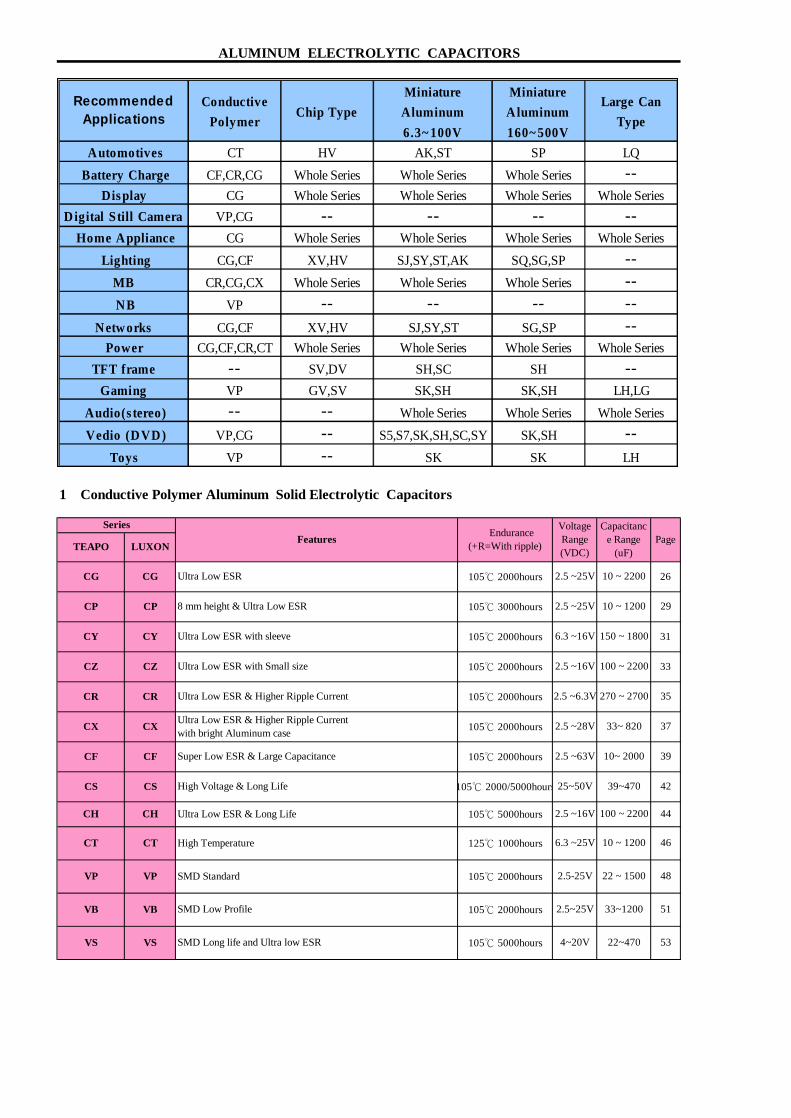
1 Conductive Polymer Aluminum Solid Electrolytic Capacitors
4~20V 22~470 53VS VS SMD Long life and Ultra low ESR 105℃ 5000hours
VB
VP VP SMD Standard
SMD Low Profile 33~1200
105℃ 2000hours
105℃ 2000hours 2.5~25VVB 51
44
2.5-25V 22 ~ 1500 48
6.3 ~25V 10 ~ 1200
VoltageRange(VDC)
42
CF
CS CS High Voltage & Long Life 105℃ 2000/5000hours
105℃ 2000hours 39
39~470
ALUMINUM ELECTROLYTIC CAPACITORS
TEAPO
8 mm height & Ultra Low ESR 105℃ 3000hours
Endurance(+R=With ripple)
31
26
2.5 ~25V 10 ~ 1200
105℃ 2000hours 10 ~ 2200
29
CG Ultra Low ESR 2.5 ~25V
105℃ 2000hours 6.3 ~16V 150 ~ 1800
CP CP
CY CY Ultra Low ESR with sleeve
Ultra Low ESR & Higher Ripple Currentwith bright Aluminum case
Capacitance Range
(uF)Page
Series
CG
LUXONFeatures
CZ CZ Ultra Low ESR with Small size 100 ~ 2200 33
CR 35
105℃ 2000hours 2.5 ~16V
270 ~ 2700
33~ 820 37
10~ 2000Super Low ESR & Large Capacitance
105℃ 2000hours
2.5 ~63V
CR
Ultra Low ESR & Long Life 105℃ 5000hours 2.5 ~16V
Ultra Low ESR & Higher Ripple Current 105℃ 2000hours 2.5 ~6.3V
2.5 ~28V
CF
25~50V
CX CX
46
CH CH
CT CT High Temperature 125℃ 1000hours
100 ~ 2200
RecommendedApplications
Conductive
P o lym erC h ip Type
M in iatu re
A lum inum
6.3~ 100V
M in iatu r e
A lum inum
160~ 500V
Large Can
Type
A u tom otives CT HV AK,ST SP LQ
Battery C harge CF,CR,CG Whole Series Whole Series Whole Series -- D is p lay CG Whole Series Whole Series Whole Series Whole Series
D ig ital S till Cam era VP,CG -- -- -- -- H om e A pp liance CG Whole Series Whole Series Whole Series Whole Series
Light ing CG,CF XV,HV SJ,SY,ST,AK SQ,SG,SP -- M B CR,CG,CX Whole Series Whole Series Whole Series -- N B VP -- -- -- --
N etw orks CG,CF XV,HV SJ,SY,ST SG,SP -- P ow er CG,CF,CR,CT Whole Series Whole Series Whole Series Whole Series
TF T fram e -- SV,DV SH,SC SH -- G am ing VP GV,SV SK,SH SK,SH LH,LG
A ud io (s tereo ) -- -- Whole Series Whole Series Whole Series
V ed io (D V D ) VP,CG -- S5,S7,SK,SH,SC,SY SK,SH -- Toys VP -- SK SK LH

2 Surface Mount Aluminum Electrolytic CapacitorsVoltageRange(VDC)
CapacitanceRange (uF)
TYPE TEAPO
3 Miniature Aluminum Electrolytic Capacitors
TYPE TEAPO
*47~1000
1~1000
6.3~35 1~47
*
*
*
*
*
1~1500
6.3~35
*
1~2200
6.3~50
DV
*
Low
leak
age
Low
Pro
file
Gen
eral
*Long life V-Chip
Low profile V-Chip
Features
Low profile V-Chip
Endurance (+R=With ripple )
85℃ 2000hours
85℃ 3000~5000hours
105℃ 1000hours
Series
Ver
tical
Chi
p
GV
ZV
HV
XV
ZV
LUXON
CV
NV
1~330
1~470
85℃ 1000hours
105℃ 1000hours
Low
Pro
file
S7
D7
H7
H5
105℃ 1000hours+R
Ger
enal
Typ
e
SH
SE(SEK)
4~50
S5
*
Endurance(+R=With ripple)
125℃ 2000hours
105℃ 3000~5000 hours+R
96
90
92
94
*
1~470
*
105℃ 2000hours+R
85℃ 2000hoursLow leakage current V-Chip
Higher temperature range V-Chip
85℃ 2000hours
85℃ 1000hours
Gen
eral
1~220006.3~500
SM
SE
General purpose
Miniature General purpose
1~15000
*GRSK
*
*
HV
105℃ 1000hours
105℃ 2000hours
105℃ 2000hours
*
XV
NV
7 & 9 mm heightSX
General purpose
Features
CV
Ultra Low impedance V-Chip
Series
LUXON
*
6.3~450
*
* 4~50
82
1~4704~63
6.3~500 1~22000 85
1~470
4~63
4~63
98
*
*
*
ALUMINUM ELECTROLYTIC CAPACITORS
4~50 1~220D5 5 mm height 88*SF
79
Page
H7
SS
105℃ 1000hours
105℃ 2000hours
5 mm heightFX
H5 5 mm height
7 & 9 mm height
7 & 9 mm height
Low
Impe
danc
e
Long
Life
Min
latu
re
Low
impe
danc
e
Page
Long
Life Voltage
Range(VDC)
CapacitanceRange (uF)
4~100
DV
YV
EV
105℃ 1000~2000hours+RYV
Long life V-Chip
Low impedance V-Chip
105℃ 2000hours
Low impedance V-Chip
GV
FV
SV
57
SV * *
55
FV * 4~100 1~1000
4~100 1~1500
63
61
59
4~50 1~1500
1~1500
6.3~450
JV
Ultra Low impedance V-Chip 105℃ 2000hours+REV
Low profile vertical chipJV
77Non-polarized V-Chip 105℃ 2000 hours
73
6.3~50 1~100 75
6.3~50
716.3~50
65
67
10~1800
6.3~50 4.7~1500
69
TYPE TEAPO
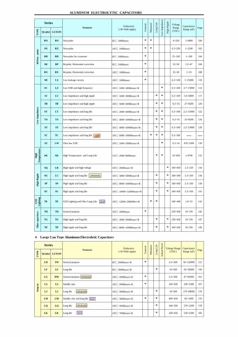
4 Large Can Type Aluminum Electrolytic Capacitors
TYPE TEAPO
160~450 220~2200 182
33~8200
270~68000
2.2~220
10~450
160~450
270~2200
6.3~100
47~82000
100~3300
1-4700
6.3~16
* 250~450
Sohe
nl R
roof
CapacitanceRange (uF)
160~450 10~330
Voltage Range(VDC)
470~3300*
10~150
3.3~330
10~150
105℃ 2000hours
105℃ 10000~12000hours+R
250~450
*
Low
Impe
danc
e
*
*
*
Slim
cap
acito
rs TH TH General purpose
TG TG High ripple and long life
136
134* 160~450
* 160~500 3.3~330*
1393.3~330
*
VoltageRange(VDC)
CapacitanceRange (uF) Page
Gen
eral
Min
iatu
re
Long
Life
Hig
h Ri
pple
LUXON
SQ LB High ripple and high voltage
SC
SJ
RN
SY
Low leakage current
Low ESR and high frequency
Endurance(+R=With ripple)
105℃ 2000hours+R
TP TP High ripple and long life 105℃ 8000~10000hours+R
SP
105℃ 3000~5000hours+R
SeriesFeatures
149
LC
* *
* *
147
145
LK LK
HW
170
167LS
LJ
160~450
10~500Long life
6.3~500
LQ
LJ
LS
160~500
TW
Page
56~120000
ALUMINUM ELECTROLYTIC CAPACITORS
LG
85℃ 2000hours+R
*
LH
General purpose
151
161
Min
iatu
re
Long
LifeSeries
Features Endurance(+R=With ripple)
*
Gen
eral
General purpose
LUXON
105℃ 3000~5000hours+R
High ripple and long life
High ripple and long life
SP
RB
BX
SRBi/N
on -
pola
r
105℃ 1000~3000hours+R
SB
85℃ 1000hours * *Non-polar
1175.6~6800
6.3~100
4.7~15000
6.3~100
114
*
1~15000 110
25~50 1~33
*
1~100
25~50
100
102
104
105℃ 1000hours *
85℃ 1000hours
1~6800
6.3~250* *
4~250
27~8200 120
108
106
1~2200
25~100
6.3~100
6.3~35
2.2~47*
105℃ 1000hours
*
6.3~100 2.2~15000
*
126
122
* *
Non-polar
Non-polar for crossover
Bi-polar, Horizontal correction
105℃ 1000hours
85℃ 1000hours
TA TA Low impedance and long life
Bi-polar, Horizontal correction
LZ
SN
Low impedance and high rippleLU
LT
* *
* *
*
* *
105℃ 1000~5000hours+R
Low impedance and long life
125℃ 2000-5000hours
105℃ 4000~10000hours+R
105℃ 2000~6000hours+R
105℃ 1000~2000hours+R
105℃ 4000~10000hours+R
Low impedance and long life
Ultra low ESR
RN
RX
RB
BP
BX
LX
SU SU
ST
LW
AKAK
ST
SZ
SG
TC
141* * 160~450
178
*
160~400 1.0~33
132
128
130
2.2~15000
6.3~100 --- ---
LQ Long life 105℃ 5000hours+R *
High ripple and long life
*
*105℃ 3000hours+R
High Temperature and Long Life
6.3~35
*
Snap
-in
TB TB Low impedance and high ripple 105℃ 5000~6000hours+R
*Long life 105℃ 7000hours+R
Hig
h R
ippl
e
*
105℃ 12000~20000Hrs+R *
105℃ 8000~10000hours+R
143
Low
Impe
danc
eH
igh
Tem
pera
ture
LED
Ligh
ting
TE TE LED Lighting and Ultra Long Life
TC Low impedance and long life 105℃ 6000~10000hours+R
LF LF Long life 85℃ 3000hours+R *
Smaller size
105℃ 2000hours+R
*
LM LM Smaller size and long life 105℃ 3000hours+R *
105℃ 2000hours+R
400~450 82~1000 176
10~450 56~56000 156
6.3~500
NEW
NEW
NEW
TBD
UPGRADE
UPGRADE
UPGRADE
UPGRADE

1-1 Precautions in Using Aluminum Electrolytic Capacitors
Please note the following recommendations when using capacitors:
10. Keep the following clearance between the vent of the capacitor
and the case of the appliance . Do not block the operation of the
vent , unless otherwise described on the catalogues or product
specifications . The narrower clearance may adversely affect the
vent operation and result in an explosion of the capacitor .
Case diameter Clearance
ψ6.3 to ψ16 mm 2 mm minimum
ψ18 to ψ 35 mm 3 mm minimum
ψ40 mm & up 5 mm minimum
Fig.1-1
-size electrolytic capacitors , nothing abnormal will be occurred if
3. Do not allow excessive ripple current passing.
2. Do not apply a voltage exceeding the capacitor's voltage rating .
If a voltage exceeding the capacitor's voltage rating is applied , the
capacitor may be damaged by increased leakage current . When
using the capacitor with AC voltage do not exceed the rated voltage .
Halogenated hydrocarbon cleaning solvents are not recommended
for use in cleaning capacitors supplied with exposed end seals .
Where cleaning with a halogenated solvent is desired , capacitors
the necessary voltage treatment before use .
If used in circuits which are charged and discharged repeatedly , the
electrolytic capacitors cannot be used for AC applications .
capacitors for high ripple current applications .
Use the electrolytic capacitors according to the specified operation
4. Ascertain the operation temperature range .
ALUMINUM ELECTROLYTIC CAPACITORS
1. Electrolytic capacitors for DC applications require polarization .
Confirm the polarity before use . The circuit life may be shortened
or the capacitor may be damaged if insert in reversed polarity . For
polarity is unknown , use non-polar capacitors . Also note that the
8. Cleaning circuit boards after soldering .
should be ordered with an Epoxy-coated end seal .
6. When capacitors have been left unused for long time , use them only
temperature range . Use at room temperature will ensure a longer
life .
5. The electrolytic capacitor is not suitable for circuits which are
charged and discharged repeatedly .
capacitance value may drop or the capacitor may be damaged .
Please consult our engineering department for assistance in these
applications .
ripple range . If the ripple exceeds the specified value , request
9. Do not apply excessive force to the lead wires or terminals .
If excessive force is applied to the lead wires and terminals , they
Attention
may be broken or their connections on the internal elements may
be affected . (For strength of terminals , please refer to JIS C 5101
-1:2010and C 5101-4:2010 . )
•The description in this catalogue is subject to change without prior7. Be careful of temperature and time when soldering .
Use the electrolytic capacitor at current value within the permissible
notice for product improvement . Therefore , please confirm the
specification before ordering products .•The general characteristics , reliability data , etc ., described in this
catalogue should not be construed as guaranteed values , they are
and insulation sleeve of electrolytic capacitors . In the case of small
use on circuits whose polarity is occasionally reversed , or whose
Otherwise , there will be adverse effect on the electrical characteristics
When soldering a printed circuit board with various components ,
after due voltage treatments . Long storage of capacitors tends to
rise their leakage current levels . In such cases , be sure to provide
dipping is performed at less than 260℃ for less than 10 seconds .
merely standard values .•Before using the products , please read the notes in this catalogue
carefully for proper use .
and that the dipping time is not too long .
care must be taken that the soldering temperature is not too high

1-2 Technical Concepts 1-3 The Function of Electrolytic Capacitors
1. The material and structure of Electrolytic Capacitors The electrolytic capacitors could be widely used in appliance (ie. TV , radio ,
Electrolytic Capacitor is a simple module . It simply contains an insulator audio equipment , washing machine and air conditioner……etc . ) , computer
between relative conductors in an electrode. The major internal raw material equipment (mother board, image device & the peripherals such as the printer
contains an element constructed by an separator paper wrap around the , drawing device, scanner…etc) , communication equipment , estate equipment
anode foil and cathode foil , which is then impregnated with the electrolyte , measure instrument and also the industrial instrument , airplane , firebomb ,
, inserted into an aluminum case and sealed. satellite…etc. as a piloting equipment.
*According to the inflict electric wave & using purpose , it basically with some
classified purposes as below :
1. DC Voltage :
a. For Momentary High Voltage : For using to the impulse generator such as
the shock wave resistance test of the heavy electric machine .
b. For High Electric Current : For using to the welding machine , X- Ray
facility , copy machine and discharge processing device .
c. For DC High Voltage : The electrolytic capacitor and rectifier composing
, a special DC high voltage been happened after charged , for using to the
power of electronic microscope and accelerator .
d. For Integration & Memory : For either memory circuit or compare circuit
inside the calculator .
2. The DC voltage that with alternate ingredient :
a. For Wave Filter : Combination with the chip resistor & inductor as a internet
, to be past by DC current or some frequency to closure or decline some
other frequency .
b. For Bypass : A parallel track that outside from the circuit element , the IC
2. Production Processes (integrated circuit) has been rapidly developing in this years and thus a
1. Etching : The process to increase surface area of aluminum foil by using miniaturization or chip of electrolytic capacitors for by pass was
chemical erosion or chemical corrosion method is called Etching . conducted .
Normally chemical corrosion method uses the ripple current of c. For Coupling : Combination of the electrolytic capacitor , chip resistor and
electrolyte , combination of the liquid and temperature to determine inductor and thus coupling together .
the size, shape , and quantity of the dense network of microscopic d. For Arising of Toothed Wave : Composing of RC charge/ discharge circuit
channels on the aluminum foil surface . through the electrolytic capacitor as well as the resistor and a toothed wave
2. Forming : The production process of the anode aluminum foil of electrolytic to be created by the RC charge/discharge circuit .
capacitors is by anodic oxidation of the etched aluminum foil . e. For Reverse (Change) of Circuit : The equipment for change the AC
The production of the cathode aluminum foil sometimes involves voltage to DC voltage .
oxidation in special purposes . This anodic oxidation process is
called Forming . Boric acid or organic acid is used for high voltage 3. For AC voltage :
forming and phosphoric acid or ammonium adipate is used for a. For Power Improving : Connect the end loading of layout transporting &
low voltage forming in order to obtain stable natural oxide layer electrolytic capacitor for power improving . of Al2O3 . b. For Wave Filter : Prevention of external interference in SCR circuit , use
3. Slitting :The cutting of the aluminum foil and separator paper according the LC wave filter circuit to inhibit or erase the interference .
to the required length . c. For Phase Across : Phase change of the inductive electromotor (motor) with
4. Winding : The stitching or cold welding of cut anode and cathode foils and single phase .
tab terminal , and wrap the electrolytic paper in between the anode
and cathode , then fix the end with glue or sticky tape , and
attached leads is called the capacitor "element" .
5. Impregnation : The process of eliminating water from the elements by
pressurizes or vacuum in order to soak the element with the
electrolyte is called Impregnation . The elements fully filled with
electrolyte is then centrifuged to remove excess electrolyte .
6. Assembly : The elements seal with rubber to stop the leakage of electrolyte
then slip into a sleeve to form the final product .
7. Aging : The purpose of Aging is to repair the oxide film damage by
recharging and electrolyte .
ALUMINUM ELECTROLYTIC CAPACITORS
Fig.1-2
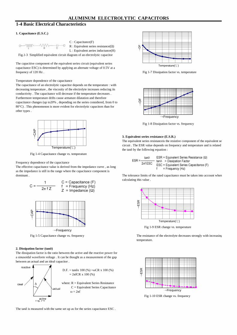
1-4 Basic Electrical Characteristics
1. Capacitance (E.S.C.)
C : Capacitance(F) R : Equivalent series resistance(Ω) L : Equivalent aeries inductance(H)
Fig.1-3 Simplified equivalent circuit diagram of an electrolytic capacitor
The capacitive component of the equivalent series circuit (equivalent series capacitance ESC) is determined by applying an alternate voltage of 0.5V at a frequency of 120 Hz . Fig 1-7 Dissipation factor vs. temperature
Temperature dependence of the capacitanceThe capacitance of an electrolytic capacitor depends on the temperature : with decreasing temperature , the viscosity of the electrolyte increases reducing its conductivity . The capacitance will decrease if the temperature decreases .Furthermore temperature drifts cause armature dilatation and therefore capacitance changes (up to20% , depending on the series considered, from 0 to 80°C) . This phenomenon is more evident for electrolytic capacitors than for other types .
Fig 1-8 Dissipation factor vs. frequency
3. Equivalent series resistance (E.S.R.)The equivalent series resistanceis the resistive component of the equivalent series circuit . The ESR value depends on frequency and temperature and is related to the tanδ by the following equation :
Fig 1-4 Capacitance change vs. temperature
Frequency dependence of the capacitanceThe effective capacitance value is derived from the impedance curve , as long as the impedance is still in the range where the capacitance component is dominant . The tolerance limits of the rated capacitance must be taken into account when
calculating this value .
Fig 1-9 ESR change vs. temperature
Fig 1-5 Capacitance change vs. frequency The resistance of the electrolyte decreases strongly with increasing temperature.
2. Dissipation factor (tanδ)The dissipation factor is the ratio between the active and the reactive power fora sinusoidal waveform voltage . It can be thought as a measurement of the gap between an actual and an ideal capacitor .
D.F. = tanδx 100 (%) =ωCR x 100 (%) = 2πfCR x 100 (%)
where: R = Equivalent Series Resistance C = Equivalent Series Capacitance ω = 2πf
Fig 1-10 ESR change vs. frequency Fig 1-6
The tanδ is measured with the same set up as for the series capacitance ESC .
ALUMINUM ELECTROLYTIC CAPACITORS
→C
AP
Temperature(℃)
→C
AP
→Frequency
→D
F
Temperature(℃)
→D
F
→Frequency
→ES
R
Temperature(℃)
→ES
R
→Frequency
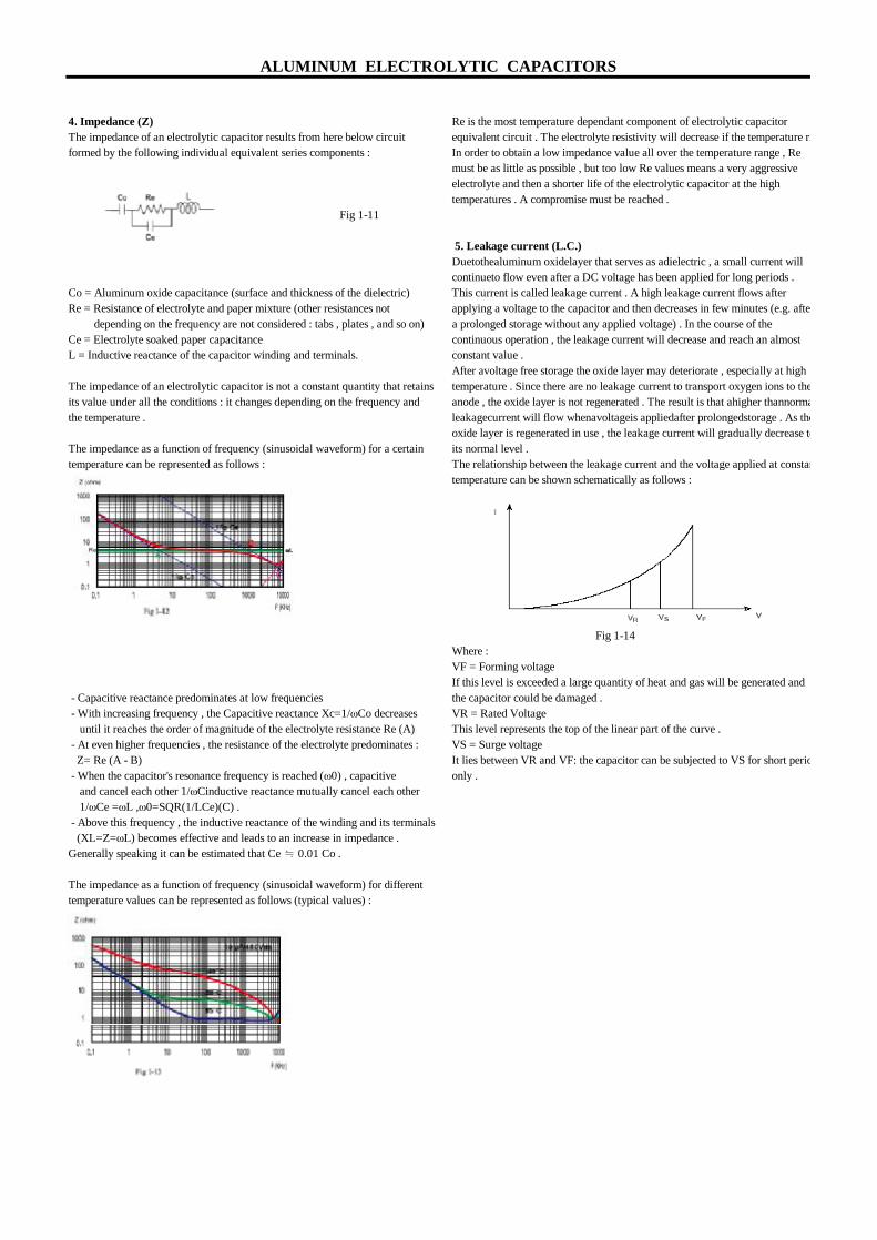
4. Impedance (Z) Re is the most temperature dependant component of electrolytic capacitor The impedance of an electrolytic capacitor results from here below circuit equivalent circuit . The electrolyte resistivity will decrease if the temperature rises .formed by the following individual equivalent series components : In order to obtain a low impedance value all over the temperature range , Re
must be as little as possible , but too low Re values means a very aggressive electrolyte and then a shorter life of the electrolytic capacitor at the high temperatures . A compromise must be reached .
Fig 1-11
5. Leakage current (L.C.)Duetothealuminum oxidelayer that serves as adielectric , a small current will continueto flow even after a DC voltage has been applied for long periods .
Co = Aluminum oxide capacitance (surface and thickness of the dielectric) This current is called leakage current . A high leakage current flows after Re = Resistance of electrolyte and paper mixture (other resistances not applying a voltage to the capacitor and then decreases in few minutes (e.g. after depending on the frequency are not considered : tabs , plates , and so on) a prolonged storage without any applied voltage) . In the course of theCe = Electrolyte soaked paper capacitance continuous operation , the leakage current will decrease and reach an almost L = Inductive reactance of the capacitor winding and terminals. constant value .
After avoltage free storage the oxide layer may deteriorate , especially at high The impedance of an electrolytic capacitor is not a constant quantity that retains temperature . Since there are no leakage current to transport oxygen ions to the its value under all the conditions : it changes depending on the frequency and anode , the oxide layer is not regenerated . The result is that ahigher thannormal the temperature . leakagecurrent will flow whenavoltageis appliedafter prolongedstorage . As the
oxide layer is regenerated in use , the leakage current will gradually decrease to The impedance as a function of frequency (sinusoidal waveform) for a certain its normal level .temperature can be represented as follows : The relationship between the leakage current and the voltage applied at constant
temperature can be shown schematically as follows :
Fig 1-14Where :VF = Forming voltageIf this level is exceeded a large quantity of heat and gas will be generated and
- Capacitive reactance predominates at low frequencies the capacitor could be damaged . - With increasing frequency , the Capacitive reactance Xc=1/ωCo decreases VR = Rated Voltage until it reaches the order of magnitude of the electrolyte resistance Re (A) This level represents the top of the linear part of the curve . - At even higher frequencies , the resistance of the electrolyte predominates : VS = Surge voltage Z= Re (A - B) It lies between VR and VF: the capacitor can be subjected to VS for short periods - When the capacitor's resonance frequency is reached (ω0) , capacitive only . and cancel each other 1/ωCinductive reactance mutually cancel each other 1/ωCe =ωL ,ω0=SQR(1/LCe)(C) . - Above this frequency , the inductive reactance of the winding and its terminals (XL=Z=ωL) becomes effective and leads to an increase in impedance .Generally speaking it can be estimated that Ce ≒ 0.01 Co .
The impedance as a function of frequency (sinusoidal waveform) for different temperature values can be represented as follows (typical values) :
ALUMINUM ELECTROLYTIC CAPACITORS
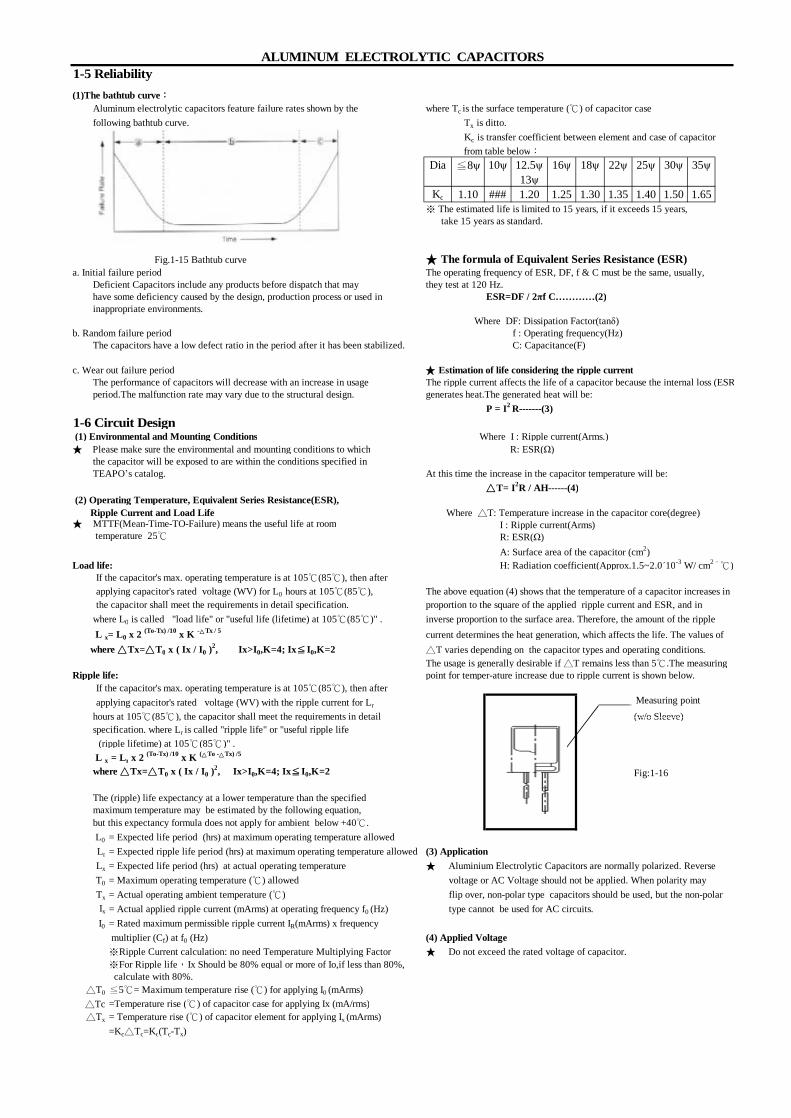
1-5 Reliability(1)The bathtub curve: Aluminum electrolytic capacitors feature failure rates shown by the where Tc is the surface temperature (℃) of capacitor case following bathtub curve. Tx is ditto.
Kc is transfer coefficient between element and case of capacitor from table below:
Dia ≦8ψ 10ψ 12.5ψ 16ψ 18ψ 22ψ 25ψ 30ψ 35ψ13ψ
Kc 1.10 ### 1.20 1.25 1.30 1.35 1.40 1.50 1.65※ The estimated life is limited to 15 years, if it exceeds 15 years, take 15 years as standard.
★ The formula of Equivalent Series Resistance (ESR)a. Initial failure period The operating frequency of ESR, DF, f & C must be the same, usually, Deficient Capacitors include any products before dispatch that may they test at 120 Hz. have some deficiency caused by the design, production process or used in ESR=DF / 2πf C…………(2) inappropriate environments.
Where DF: Dissipation Factor(tanδ)b. Random failure period f : Operating frequency(Hz) The capacitors have a low defect ratio in the period after it has been stabilized. C: Capacitance(F) c. Wear out failure period ★ Estimation of life considering the ripple current The performance of capacitors will decrease with an increase in usage The ripple current affects the life of a capacitor because the internal loss (ESR) period.The malfunction rate may vary due to the structural design. generates heat.The generated heat will be:
P = I2 R-------(3)1-6 Circuit Design (1) Environmental and Mounting Conditions Where I : Ripple current(Arms.)★ Please make sure the environmental and mounting conditions to which R: ESR(Ω) the capacitor will be exposed to are within the conditions specified in TEAPO’s catalog. At this time the increase in the capacitor temperature will be:
△T= I2R / AH------(4) (2) Operating Temperature, Equivalent Series Resistance(ESR), Ripple Current and Load Life Where △T: Temperature increase in the capacitor core(degree)
I : Ripple current(Arms) R: ESR(Ω) A: Surface area of the capacitor (cm2)
Load life: H: Radiation coefficient(Approx.1.5~2.0´10-3 W/ cm2.℃) If the capacitor's max. operating temperature is at 105℃(85℃), then after applying capacitor's rated voltage (WV) for L0 hours at 105℃(85℃), The above equation (4) shows that the temperature of a capacitor increases in the capacitor shall meet the requirements in detail specification. proportion to the square of the applied ripple current and ESR, and in
where L0 is called "load life" or "useful life (lifetime) at 105℃(85℃)" . inverse proportion to the surface area. Therefore, the amount of the ripple L x= L0 x 2 (To-Tx) /10 x K -△Tx / 5 current determines the heat generation, which affects the life. The values of where △Tx=△T0 x ( Ix / I0 )
2, Ix>I0,K=4; Ix≦I0,K=2 △T varies depending on the capacitor types and operating conditions. The usage is generally desirable if △T remains less than 5℃.The measuringRipple life: point for temper-ature increase due to ripple current is shown below.
If the capacitor's max. operating temperature is at 105℃(85℃), then after applying capacitor's rated voltage (WV) with the ripple current for Lr
hours at 105℃(85℃), the capacitor shall meet the requirements in detail (w/o Sleeve) specification. where Lr is called "ripple life" or "useful ripple life
(ripple lifetime) at 105℃(85℃)" . L x = Lr x 2 (To-Tx) /10 x K (△To -△Tx) /5
Fig:1-16
The (ripple) life expectancy at a lower temperature than the specified maximum temperature may be estimated by the following equation, but this expectancy formula does not apply for ambient below +40℃.
L0 = Expected life period (hrs) at maximum operating temperature allowed Lr = Expected ripple life period (hrs) at maximum operating temperature allowed (3) ApplicationLx = Expected life period (hrs) at actual operating temperature ★ Aluminium Electrolytic Capacitors are normally polarized. ReverseT0 = Maximum operating temperature (℃) allowed voltage or AC Voltage should not be applied. When polarity may Tx = Actual operating ambient temperature (℃) flip over, non-polar type capacitors should be used, but the non-polar Ix = Actual applied ripple current (mArms) at operating frequency f0 (Hz) type cannot be used for AC circuits.I0 = Rated maximum permissible ripple current IR(mArms) x frequency
multiplier (Cf) at f0 (Hz) (4) Applied Voltage※Ripple Current calculation: no need Temperature Multiplying Factor ★ Do not exceed the rated voltage of capacitor.※For Ripple life,Ix Should be 80% equal or more of Io,if less than 80%, calculate with 80%.
△T0 ≦5℃= Maximum temperature rise (℃) for applying I0 (mArms) △Tc =Temperature rise (℃) of capacitor case for applying Ix (mA/rms)△Tx = Temperature rise (℃) of capacitor element for applying Ix (mArms)
=Kc△Tc=Kc(Tc-Tx)
where △Tx=△T0 x ( Ix / I0 )2, Ix>I0,K=4; Ix≦I0,K=2
temperature 25℃
Fig.1-15 Bathtub curve
★ MTTF(Mean-Time-TO-Failure) means the useful life at room
ALUMINUM ELECTROLYTIC CAPACITORS
Measuring point

(5) Insulation (3) Soldering★ Aluminum Electrolytic Capacitors should be electrically isolated ★ All TEAPO's cp wires of electrolytic capacitors are without lead (Pb). from among the following points. ★ Soldering conditions(temperatures, times) should be within the
specified conditions which are described in the catalog or specification sheets. a. Aluminum case, cathode lead wire, anode lead wire and circuit pattern.★ If it is necessary that the leads must be formed due to a mismatch of the b. Auxiliary terminals of snap-in type, anode terminal, outward terminal lead space to hole space on the board, bend the lead prior to soldering and circuit pattern. without applying too much stress to the capacitor.
★ If soldering capacitor has to be withdrawn from the PW board by soldering(6) Conditions of use iron, the capacitor should be removed after the solder has melted sufficiently in ★ Aluminum Electrolytic Capacitors must not be used under the order to avoid stress to the capacitor or lead wires. following conditions: ★ Soldering iron should never touch the capacitor's body. a. Damp conditions such as water, saltwater spray, or oil spray or ★ Besides SMD for polymer type,do not reflow soldering for other type capacitors. fumes. High humidity or humidity condensation situations ★ No high temperature b. Ambient conditions that include toxic gasses such as hydrogen sulfide, sulfurous acid , nitrous acid, chlorine, ammonium, etc. (4) Flow soldering c. Ambient conditions that expose the capacitors to ozone, ★ Do not dip capacitor's body into melted solder. ultraviolet rays and radiation. ★ Din of flow soldering for the capacitors should be limited at 260℃,10sec. d. Severe vibration or shock that exceeds the conditions specified ★ Flux should not be adhered to capacitor's body but only to its terminals. in the catalog or specifications sheets. ★ Other devices which are mounted near capacitors should not touch
the capacitors.(7) Recommended design considerations★ When designing a circuit board. Please pay attention to the following: (5) Lead free type reflow soldering condition(SMD For E-CAP) a. Make the hole spacing on the PC board match the lead space For Aluminum Electrolytic Capacitors of the capacitor. ★ For reflow, use a thermal condition system such as infrared radiation b. There should not be any circuit pattern or circuit wire above or hot blast. Vapor heat transfer systems are not recommended. the capacitors. ★ Observe proper soldering conditions(temperature, time, etc. c. In case the capacitor's vent is facing the PC board, make a gas Do not exceed the specified limits. release hole on PC board. ★ Repeated reflowing : d. Do not install screw terminal capacitor with end seal side down. *Avoid reflowing twice if possible. When you install a screw terminal capacitor in a horizontal mount, *If repeated reflowing is unavoidable,contact us after measuring the the positive terminal must be in the upper position. first and the second reflow profiles and reflow interval at your side. e. Do not locate any wiring and circuit patterns directly above the *Do not attempt to reflow three times. capacitor's vent.
1-7 Caution for Mounting
(1) Caution before assembly★ Aluminum Electrolytic Capacitors cannot be recycled after mounting and applying electricity in unit. The capacitors that are removed from PC board for the purpose of measuring electrical characteristics at a periodical inspection should only berecycled to the same position.★ Aluminum Electrolytic Capacitors may accumulate charge naturally during storage. In this case, discharge through a 1KΩ resistor before use.★ Leakage current of Aluminum Electrolytic Capacitors may Fig:1-17 be increase during long storage time. In this case, the capacitors should be subject to voltage treatment through a 1KΩ resistor t before use.
(2) In the assembly process★ Please confirm ratings before installing capacitors on the PC board.★ Please confirm polarity before installing capacitors on the PC board.★ Do not drop capacitors on the floor, nor use a capacitor that was dropped.★ Be careful not to deform the capacitor during installation.★ Please confirm that the lead spacing of the capacitor matches the hole spacing of the PC board prior to installation.★ The snap-in type of capacitors should be mounted firmly on the PC board without a gap between the capacitor body and the surface of PC board.★ Avoid excessive force when clinching lead wire during auto-insertion process.★ Avoid excessive shock to capacitors by automatic insertion machine, during mounting, parts inspection or centering operations. ★ Please utilize supporting material such as strap or adhesive to mount capacitors to PC board when it is anticipated that vibration or shock is applied.
10
260 5
5
ALUMINUM ELECTROLYTIC CAPACITORS
63〜100V5
TSize
φ4〜φ5(4V〜50V)
250
φ6.3〜φ10(4V〜50V)
250
250φ4〜φ10
25
160
220
Preheat (160 ~ 190℃)
120 sec (max)
Peak temperature T ℃
t sec (max)
60 sec (max)
90 sec (max)
19
Tem
pera
ture
at le
ad o
f cap
acito
r (℃
)
Time (sec)
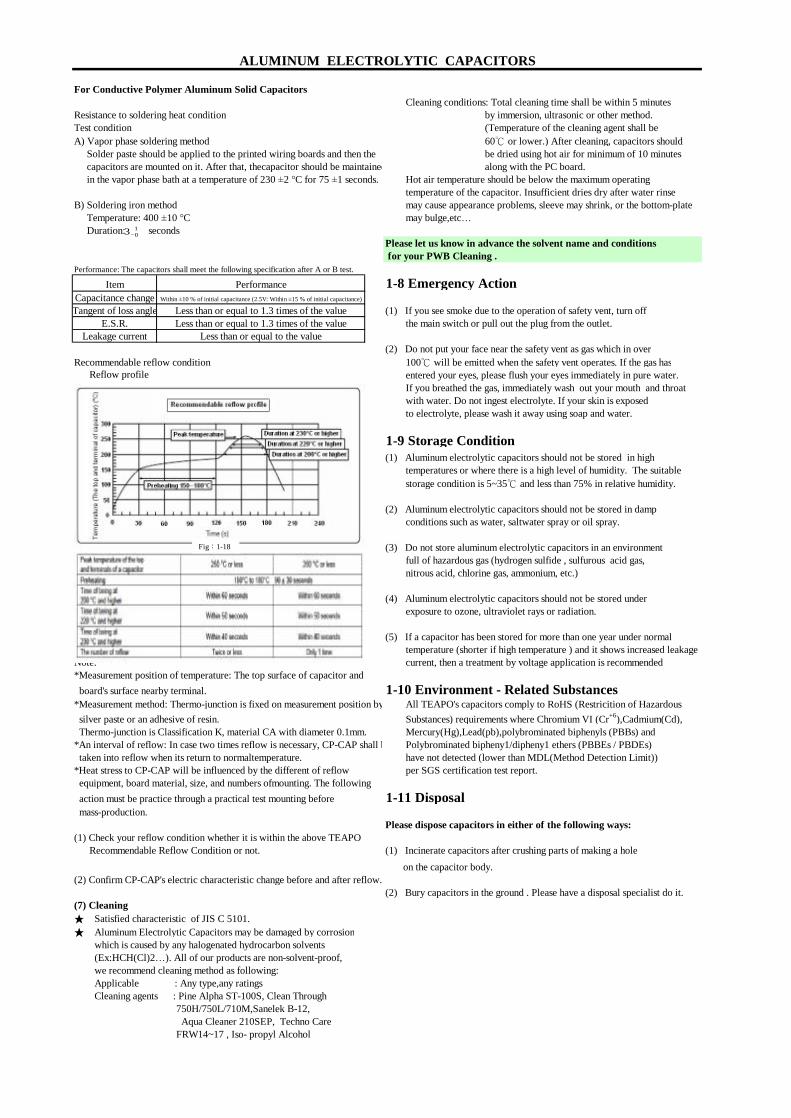
For Conductive Polymer Aluminum Solid Capacitors Cleaning conditions: Total cleaning time shall be within 5 minutes
Resistance to soldering heat condition by immersion, ultrasonic or other method. Test condition (Temperature of the cleaning agent shall be A) Vapor phase soldering method 60℃ or lower.) After cleaning, capacitors should Solder paste should be applied to the printed wiring boards and then the be dried using hot air for minimum of 10 minutes
capacitors are mounted on it. After that, thecapacitor should be maintained along with the PC board. in the vapor phase bath at a temperature of 230 ±2 °C for 75 ±1 seconds. Hot air temperature should be below the maximum operating temperature of the capacitor. Insufficient dries dry after water rinseB) Soldering iron method may cause appearance problems, sleeve may shrink, or the bottom-plate Temperature: 400 ±10 °C may bulge,etc… Duration: seconds
Please let us know in advance the solvent name and conditions for your PWB Cleaning .
1-8 Emergency Action
(1) If you see smoke due to the operation of safety vent, turn off the main switch or pull out the plug from the outlet.
(2) Do not put your face near the safety vent as gas which in over Recommendable reflow condition 100℃ will be emitted when the safety vent operates. If the gas has Reflow profile entered your eyes, please flush your eyes immediately in pure water.
If you breathed the gas, immediately wash out your mouth and throat with water. Do not ingest electrolyte. If your skin is exposed to electrolyte, please wash it away using soap and water.
1-9 Storage Condition(1) Aluminum electrolytic capacitors should not be stored in high temperatures or where there is a high level of humidity. The suitable storage condition is 5~35℃ and less than 75% in relative humidity.
(2) Aluminum electrolytic capacitors should not be stored in damp conditions such as water, saltwater spray or oil spray.
(3) Do not store aluminum electrolytic capacitors in an environment full of hazardous gas (hydrogen sulfide , sulfurous acid gas, nitrous acid, chlorine gas, ammonium, etc.)
(4) Aluminum electrolytic capacitors should not be stored under exposure to ozone, ultraviolet rays or radiation.
(5) If a capacitor has been stored for more than one year under normal temperature (shorter if high temperature ) and it shows increased leakage
Note: current, then a treatment by voltage application is recommended*Measurement position of temperature: The top surface of capacitor and board's surface nearby terminal. 1-10 Environment - Related Substances*Measurement method: Thermo-junction is fixed on measurement position by All TEAPO's capacitors comply to RoHS (Restricition of Hazardous silver paste or an adhesive of resin. Substances) requirements where Chromium VI (Cr+6),Cadmium(Cd), Thermo-junction is Classification K, material CA with diameter 0.1mm. Mercury(Hg),Lead(pb),polybrominated biphenyls (PBBs) and *An interval of reflow: In case two times reflow is necessary, CP-CAP shall be Polybrominated bipheny1/dipheny1 ethers (PBBEs / PBDEs)
taken into reflow when its return to normaltemperature. have not detected (lower than MDL(Method Detection Limit))*Heat stress to CP-CAP will be influenced by the different of reflow per SGS certification test report.
equipment, board material, size, and numbers ofmounting. The following action must be practice through a practical test mounting before 1-11 Disposal mass-production.
Please dispose capacitors in either of the following ways:(1) Check your reflow condition whether it is within the above TEAPO Recommendable Reflow Condition or not. (1) Incinerate capacitors after crushing parts of making a hole
on the capacitor body.(2) Confirm CP-CAP's electric characteristic change before and after reflow.
(2) Bury capacitors in the ground . Please have a disposal specialist do it.(7) Cleaning ★ Satisfied characteristic of JIS C 5101.★ Aluminum Electrolytic Capacitors may be damaged by corrosion which is caused by any halogenated hydrocarbon solvents (Ex:HCH(Cl)2…). All of our products are non-solvent-proof, we recommend cleaning method as following: Applicable : Any type,any ratings Cleaning agents : Pine Alpha ST-100S, Clean Through
750H/750L/710M,Sanelek B-12, Aqua Cleaner 210SEP, Techno Care
FRW14~17 , Iso- propyl Alcohol
Less than or equal to 1.3 times of the valueLeakage current Less than or equal to the value
ALUMINUM ELECTROLYTIC CAPACITORS
Performance: The capacitors shall meet the following specification after A or B test.
Item PerformanceCapacitance change Within ±10 % of initial capacitance (2.5V: Within ±15 % of initial capacitance)
Tangent of loss angle Less than or equal to 1.3 times of the valueE.S.R.
Fig:1-18
103+
−

The Characterisitics of Endurance Test
Capacitance Change Ratio
Dissipation Factor Change
Leakage Current Change
ALUMINUM ELECTROLYTIC CAPACITORS

Internal Phenomenon
ALUMINUM ELECTROLYTIC CAPACITORS
Failure Mode
Main Factor
Production Factor Application Factor
Typical Failure Modes and Their Factors
Vent operated
Leakagecurrentincreased
tanδincreased
Capacitance
Short
Open
Increase ininternalpressure
Increase in internal temperatur
Deterioration of oxide film
Reduced cathode foil capacitance
Reduced anodefoil capacitance
Electrolyte
Insulation breakdown of film or electrolytic
Leads improperly connected
Corrosion Infiltrationof Cl
Metal particles in
Burrs on foil or
Mechanical
Leads
Defect in oxide film
Insufficient electrolyte
Over voltage applied
Excessive ripple current
Reverse voltage applied
Used in a high
temperature
Stress applied to
leads
Used for a long period
of time
Used for Halongenated

Part Number Instruction
1 2~3 4~6 7 8~10 11~12 13 14 15 16~17 18
K SK 107 M 6R3 S1 A 1 C 11 KTYPE SERIES CAP TOL. VOLTAGE LEAD SPEC. SLEEVE CASE SIZE LENGTH OTHERS
Code 1 TypeCode
DKVLSP
Code 2~3 Series Name (as content page 6 to page 8)
Code 4~6 Capacitance 0.47μF = 474
4.7μF = 47547μF = 476
470μF = 4774700μF = 478
Code 7 Tolerance M = ±20% , K = ±10% ,V = +20〜-10%
2.5V = 2R5 100V = 1005V = 005 450V = 450
6.3V = 6R363V = 063
01
124
123
SMD (V-chip) Type (Nylon coating)
T : Ammo tape
T Ammo formed tape with pitch 2.5mm (available for dia.4~5mm) Ammo tape with straight lead (available for dia. 4~8mm) Standard ammo tape (pitch 5mm for dia .~ 13mm)
Code 11&12
C : Straight cut K : Kink(Crimp)cut
Description
R Standard reel tape (pitch 5mm for dia.~ 10mm) Reel tape with straight lead (available for dia. 4~8mm) Reel formed tape with pitch 2.5mm (available for dia.4~5mm )
Snap-in Type (PVC sleeve)
S Standard Dip & Snap-in type Standard SMD type
R : Reel tapeF : Formed cut
ALUMINUM ELECTROLYTIC CAPACITORS
Code 11~12 Lead ProcessExplanation for code 11
S : Standard
Code 8~10 Voltage
Snap-in Type (PET sleeve)Conductive Polymer Aluminum Solid Capacitor
Model Type Standard Dip Type (PVC sleeve) Standard Dip Type (PET sleeve)

357
K 2
F 6
Code 13 Special Specification
H : Customer requirements U: Special packagingK: Above life specified in catalog V: SleeveL:Pins or Wire diameter W: Capacitance
Code 14 Sleeve Code
Code1
BCH
Code 15~17 Size Code
Code 15:Case Size
A B C D E F G H J3 4 5 6 6.3 7 8 10 12
K L M N P Q R S T12.5 13 16 18 20 22 25 30 35
Code 16~17:Length
For ECAP-DIP & POLYMER-DIP & SNAP-IN05 07 09 10 1A 11 1B 12 1C 13 1405 07 09 10 10.5 11 11.5 12 12.5 13 14
15 16 17 20 25 30 32 35 36 40 5015 16 17 20 25 30 32 35 36 40 50
Note: For the part hasn't been mentioned above, the Code is the same with Length.
For V-CHIP SMD01 02 03 045.4 6.2 10.2 7.7
For POLYMER SMDA1 A2 A3 A4 A5 A6 A7 A85.8 6.0 6.7 7.7 10.0 10.4 12.0 12.2
E.G.(For Code15~17):
Code 18 Other special instructions (“K” for TEAPO standard,“ 0 ” for LUXON standard )
Brown with white printing
Royal blue with golden printingSC Green with golden printingSZ GV,FV,SV,DV,RV,ZV,EV,JV,CV, (SMD standard pack & POLYMER )
ALUMINUM ELECTROLYTIC CAPACITORS
B : DF (tanδ)D : ImpedanceE : Ripple current
Kink cut lead with L : 4.5+/-0.5mm
Forming cut lead with L : 4.0+/-0.5 (Pitch : 5mm)
DescriptionCode 11&12 Straight cut lead with L : 3.2+/-0.5mm
Straight cut lead with L : 5.0+/-0.5mm
SE
CG,CP,CR,CF,CY,CZ,CT,CX,CH,VPN
F : Leakage currentC : ESR
Straight cut lead with L : 4.0+/-0.5mm
A : Standard
C
ColorSeries
Code
CodeLength
Dark blue with white printing
Length
Black with white printingS5,D5,H5,S7,D7,H7,SH,SG,SP,SB,SY,SR,BX,LH,LG,LJ,LF,SQ,LQ,AK,ST,TH,TG,TP,TA,5
SK
22*25 For SNAP-IN
Code
Case Size
CodeCase Size
Code
LENGTH
CodeLENGTH
CodeB01
Size Description4*5.4 For V-CHIP SMD
EA1 6.3*5.8 For POLYMER SMD
C11 5*11 For ECAP-DIP & POLYMER-DIPQ25
Measuring
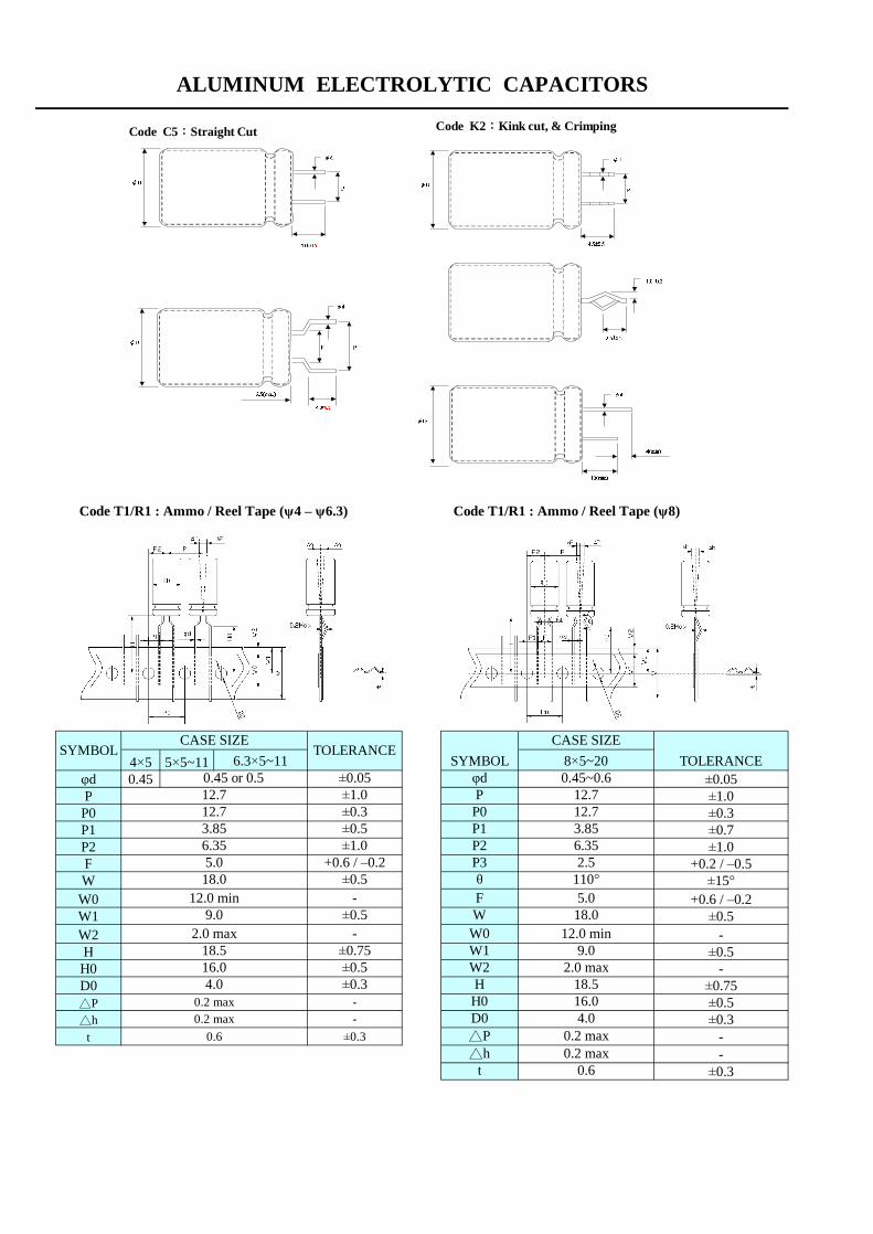
Code T1/R1 : Ammo / Reel Tape (ψ4 – ψ6.3) Code T1/R1 : Ammo / Reel Tape (ψ8)
4×5 5×5~11φd 0.45 ±0.05P ±1.0P0 ±0.3P1 ±0.7P2 ±1.0F +0.2 / –0.5W ±15°
W0 +0.6 / –0.2W1 ±0.5W2 -H ±0.5
H0 -D0 ±0.75△P ±0.5△h ±0.3
t --
±0.3
CASE SIZE
0.45 or 0.512.712.73.85
ALUMINUM ELECTROLYTIC CAPACITORS
TOLERANCESYMBOLSYMBOL TOLERANCE
6.3×5~11±0.05±1.0±0.3
0.2 max0.6
9.02.0 max
18.516.04.0
0.2 max
6.355.018.0
12.0 min
±0.3
±0.5-
±0.75±0.5±0.3
-18.5
φdPP0P1
-
±0.5±1.0
+0.6 / –0.2±0.5
P2
5.018.0
12.0 min9.0
2.0 maxW2
110°-
6.35
H
CASE SIZE8×5~200.45~0.6
12.712.73.85
2.5P3θF
D0△P
WW0W1
H0
0.6
16.04.0
0.2 max0.2 max△h
t
Code C5:Straight Cut
Code F6:Forming Cut(Φ4~Φ8)
Code K2:Kink cut, & Crimping
Code S1:Standard Type

Code T1/R1 : Ammo / Reel Tape (φ10) Code T1 : Ammo Tape (φ13~φ16)
12.5x15~250.6
Code T2/R2 : Ammo / Reel Tape with straight lead Code T4/R3 : Ammo / Reel Formed Tape (ψ4〜ψ5/pitch 2.5mm)
4×5〜7 5×5〜11 6.3×5〜11
0.451.5 2.0 2.55.6 5.35 5.1
±0.3
CASE SIZE
±0.5-
±0.75±0.3
0.7
TOLERANCE
±0.05±1.0±0.3±0.7
-
±1.3
ALUMINUM ELECTROLYTIC CAPACITORS
7.5
-
1812.0 min
5.0 +0.6 / –0.2±0.5
-
t
7.5
D0
0.2 max
SYMBOL
φdPP0
△h△P
P1P2
W2H
FWW0W1
0.2 max0.2 max
0.7
--
±0.2
φd
P0P1
P
8×7〜14TOLERANCE
CASE SIZE
0.45 or 0.5
SYMBOL
18.0
±0.05±1.0±0.3±0.5±1.0
+0.6 / –0.2
5.1
±0.5
Tolerance
0.2 max
16x16~32
Case SIZE4×5~4×7
9.02.0 max
18.54.0
0.8
2.56.35
0.455×5~5×110.45 or 0.5
12.712.7
F
SYMBOL
0.63.5
±0.05+0.6 / –0.2
SYMBOL
Fφd
12.7
H0
WW0
±1.0±1.0±0.5
-±0.5 W1
-
t△p -0.2 max
±0.20.6
17.0±0.318.5
W2H
D0H
W2 3.0 max
4.0
P1
P2
12.0 min9.0
2.0 max18.5
W1 9.0
±0.75
P2
18.012.0 min
WW0
PP0
12.76.35
±0.3±0.5
12.74.6
t
4.00.2 max0.2 max
0.6
△P△h
D0
-±0.5
-
-
±0.75±0.5±0.3
-
±0.2
10×10~30φdPP0P1P2F
0.612.7
W0
±0.05±1.0±0.3±0.5
W
6.355.0
±1.0
12.0 min
t
W1W2HD0△P△h
±0.34.0
9.02.0 max
18.5 ±0.75
CASE SIZE TOLERANCE
±0.5-
+0.6 / –0.2±0.518.0
-
3.85
30.0
3.75
13x13~320.6
15.0
5.015.0
ψ16ψ13
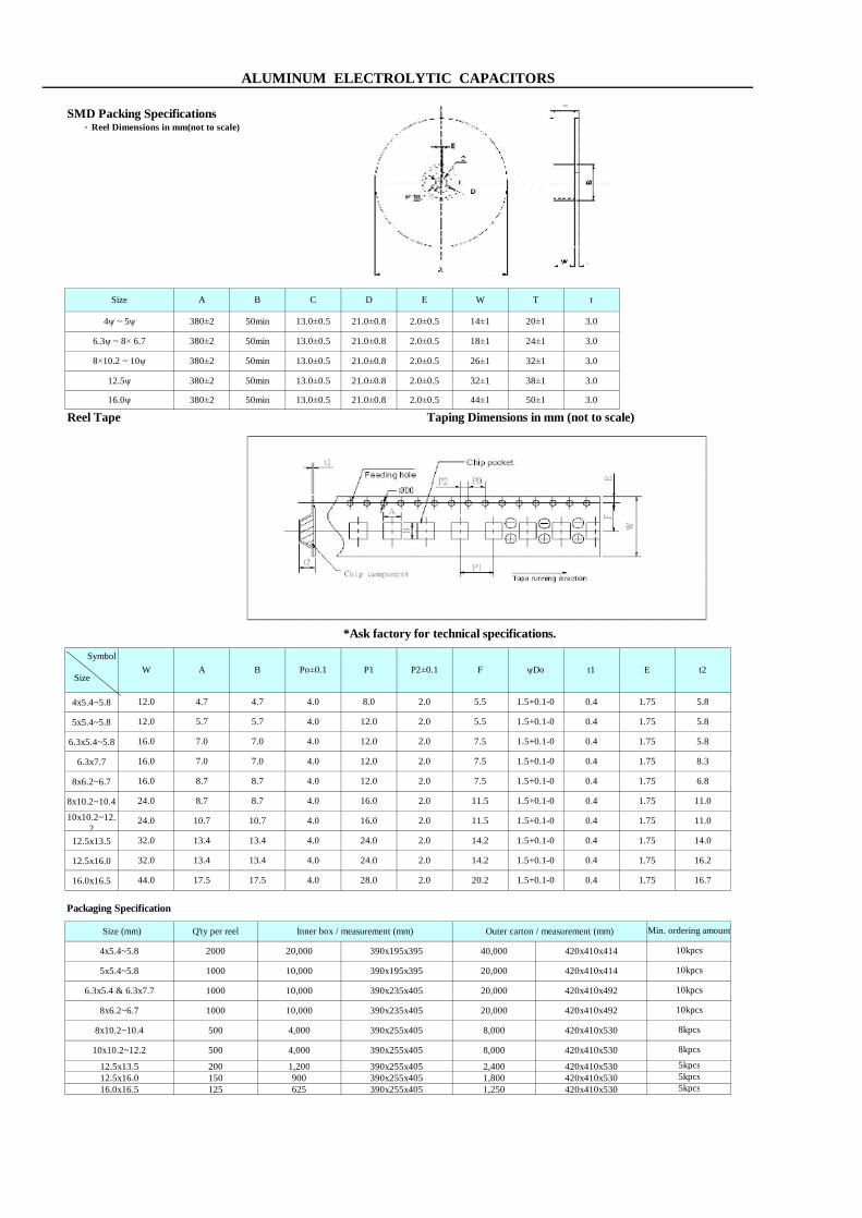
SMD Packing Specifications .Reel Dimensions in mm(not to scale)
Reel Tape Taping Dimensions in mm (not to scale)
*Ask factory for technical specifications.
Symbol
4x5.4~5.8
5x5.4~5.8
6.3x5.4~5.8
6.3x7.7
8x6.2~6.7
8x10.2~10.4
10x10.2~12.2
12.5x13.5
12.5x16.0
16.0x16.5
Packaging Specification
ALUMINUM ELECTROLYTIC CAPACITORS
1.75
1.75
8.31.750.41.5+0.1-0
5.8
5.8
11.0
E
4.7
5.7
7.0
8.7
8.7
16.0
4x5.4~5.8
5x5.4~5.8
Size (mm)
Po±0.1
16.0
A
7.0
W
12.0
12.0
16.0
B
4.7
5.7
7.0
4.0
4.0
4.0
8.7
7.0
4.0
4.0
16.0
16.0
12.0
4.0
4.0
7.5
11.5
7.5
P1
8.0
12.0
12.0
2.0
12.0
P2±0.1
2.0
2.0
2.0
5.5
7.5
0.4
0.4
0.4
0.4
390x235x405
1.75
20,000 420x410x492
Outer carton / measurement (mm)
40,000
6.8
11.01.5+0.1-0
2.0
2.0
2.0 1.75
1.75
0.411.5
10,0006.3x5.4 & 6.3x7.7
8.7
10.7
24.0
1000
Q'ty per reel
2000
24.0 10.7
500
500
4,000
10,000
8x10.2~10.4
10x10.2~12.2
8x6.2~6.7
8kpcs
8kpcs
390x255x405
8,000 420x410x530
3.0
18±1 24±1 3.0
14±1
10kpcs
10kpcs
10kpcs
10kpcs
Min. ordering amount
SizeF
5.5
1000
t2
5.8
A B tD E W T
380±2 50min 13.0±0.5 20±1
Size
4ψ ~ 5ψ 21.0±0.8 2.0±0.5
C
21.0±0.8 2.0±0.5
21.0±0.8 2.0±0.56.3ψ ~ 8× 6.7 380±2 50min 13.0±0.5
8×10.2 ~ 10ψ 380±2 50min 13.0±0.5
1000
Inner box / measurement (mm)
20,000 390x195x395
10,000 390x195x395
420x410x530
26±1 32±1 3.0
1.5+0.1-0
1.5+0.1-0 0.4
1.5+0.1-0
1.5+0.1-0
t1
420x410x530
420x410x414
20,000 420x410x414
390x235x405
4,000 390x255x405
20,000 420x410x492
8,000
0.4
5kpcs12.5x16.0 150 900 390x255x405 1,800 420x410x530 5kpcs12.5x13.5
14.2 14.0
32.0
16.0x16.5 125 625 390x255x405 1,250 420x410x530
1.5+0.1-032.0 13.4 13.4 4.0 24.0 2.0
13.4 4.0 24.0 2.0 14.2
5kpcs
200 1,200 390x255x405 2,400
1.5+0.1-0
28.0 2.0 20.2
1.75
44.0 17.5 17.5 4.0
13.4
16.7
0.4 1.75 16.2
3.0
1.5+0.1-0 0.4 1.75
ψDo
1.5+0.1-0 1.75
21.0±0.8 2.0±0.5 32±1 38±112.5ψ 380±2 50min 13.0±0.5
16.0ψ 380±2 50min 13.0±0.5 3.021.0±0.8 2.0±0.5 44±1 50±1

Conductive Polymer Aluminum Solid CapacitorsSMD Packing Specifications .Reel Dimensions in mm(not to scale)
Reel Tape Taping Dimensions in mm (not to scale)
*Ask factory for technical specifications.
Symbol
5x5.8
6.3~5.8
6.3x7.7
8x6.7
8x10.4
10x10
10x12.2
Packaging Specification
1.75
1.75
8.31.7516.0
7.0
4.0
4.0
11.0
E
5.7
7.0
8.7
8.7
B
5.7
0.41.5+0.1-0
16.0
5x5.8
Size (mm)
Po±0.1A
7.0
W
12.0
16.0
12.08.7
7.0
4.0
4.0 12.0
P1
12.0
12.0
P2±0.1
2.0
2.0
2.0
2.0
2.0
2.0
0.4
0.4
0.4
11.5
7.5
24.0
390x235x405
16.0
16.024.0 4.0
14±1380±2 50min 13.0±0.5
380±2
11.5
7.5
8.7
5.5
7.5
10kpcs
10.7
8x6.7
1000 10,0006.3x5.8~ 6.3x7.7
10.7
8x10.4 ~10x10 8kpcs390x255x405
1000
500 4,000
10,000
10kpcs
10kpcs
3.0
3.0
1.75
5.8
5.8
6.8
11.0
0.4
Min. ordering amount
SizeF
1.75
t2
A B
18±1 24±1
20±1
tD E W TSize
5ψx5.8 21.0±0.8 2.0±0.5
C
21.0±0.8 2.0±0.5
21.0±0.8 2.0±0.56.3x5.8ψ ~ 8× 6.7 50min 13.0±0.5
8×10.2 ~ 10x12.2 380±2 50min 13.0±0.5
Q'ty per reel
1000
Inner box / measurement (mm)
10,000 390x195x395
1.5+0.1-0
Outer carton / measurement (mm)
20,000 420x410x414
4.0 1.75
0.41.5+0.1-0
26±1 32±1 3.0
1.5+0.1-0
ψDo
1.5+0.1-0
1.5+0.1-0
20,000 420x410x492
420x410x492
8,000 420x410x530
390x235x405 20,000
t1
0.4 1.75 14.0
10x12.2 400 3,200 390x255x405 6,400 420x410x530
Conductive Polymer Aluminum Solid Capacitors
6.4kpcs
16.0 2.0 11.5 1.5+0.1-024.0 10.7 10.7 4.0
ALUMINUM ELECTROLYTIC CAPACITORS
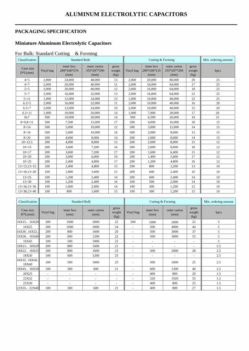
PACKAGING SPECIFICATION Miniature Aluminum Electrolytic Capacitors For Bulk: Standard Cutting & Forming
Classification Standard Bulk Cutting & Forming Min. ordering amount
Case size D*L(mm) Vinyl bag
inner box 289*168*276
(mm)
outer carton 355*297*290
(mm)
gross weight
(kg) Vinyl bag
inner box 289*168*135
(mm)
outer carton 355*297*290
(mm)
gross weight
(kg) kpcs
4×5 2,000 24,000 48,000 13 2,000 20,000 80,000 20 25 4×7 2,000 20,000 40,000 11 2,000 16,000 64,000 17 25 5×5 2,000 20,000 40,000 12 2,000 16,000 64,000 18 25 5×7 2,000 16,000 32,000 13 2,000 16,000 64,000 23 25 5×11 1,000 12,000 24,000 13 1,000 10,000 40,000 22 25 6.3×5 2,000 16,000 32,000 11 2,000 10,000 40,000 16 20 6.3×7 2,000 12,000 24,000 10 2,000 10,000 40,000 15 20 6.3×11 1,000 10,000 20,000 14 1,000 7,000 28,000 17 20
8x7 500 10,000 20,000 14 500 6,500 26,000 16 15 8×9,8×11 500 7,500 15,000 17 500 4,000 16,000 18 15
8×14 500 5,000 10,000 12 500 3,000 12,000 14 15 8×16 500 5,000 10,000 16 500 2,000 8,000 13 15 8×20 200 4,000 8,000 14 200 2,000 8,000 14 15
10×12.5 200 4,000 8,000 15 200 2,000 8,000 15 12 10×15 200 3,600 7,200 16 200 2,000 8,000 18 12 10×17 200 3,600 7,200 17 200 1,600 6,400 15 12 10×20 200 3,000 6,000 19 200 1,400 5,600 17 12 10×25 200 2,400 4,800 17 200 1,200 4,800 16 12
13×13,13×15 100 2,400 4,800 15 200 800 3,200 13 10
13×18,13×20 100 1,800 3,600 15 200 600 2,400 10 10
13×25 100 1,200 2,400 14 200 600 2,400 14 10 13×30 100 1,200 2,400 16 100 500 2,000 14 10
13×34,13×36 100 1,000 2,000 14 100 300 1,200 12 10 13×38,13×40 100 800 1,600 15 100 300 1,200 15 10
Classification Standard Bulk Cutting & Forming Min. ordering amount
Case size D*L(mm) Vinyl bag inner box
(mm) outer carton
(mm)
gross weight
(kg) Vinyl bag inner box
(mm) outer carton
(mm)
gross weight
(kg) kpcs
16X15、16X20 200 1000 2000 22 200 1000 2000 22 5 16X25 200 1000 2000 24 - 500 4000 44 5
16X30、16X32、 200 800 1600 20 - 500 3000 37 5 16X36、16X40 200 600 1200 22 - 500 3000 55 5
16X45 100 500 1000 22 - - - - 5 18X15、18X20 200 800 1600 21 - - - - 2.5 18X22、18X25 200 800 1600 23 - 500 2000 28 2.5
18X30 100 600 1200 25 - - - - 2.5 18X32、18X36、
18X40 100 500 1000 25 - 500 1000 25 2.5
18X45、18X50 100 300 600 21 - 600 1200 40 2.5 20X25 - - - - - 400 800 20 1.5 22X32 - - - - - 320 1920 55 1.5 22X30 - - - - - 400 800 25 1.5
22X35、22X40 100 300 600 21 - 400 800 27 1.5
ALUMINUM ELECTROLYTIC CAPACITORS
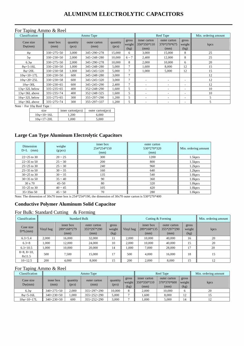
For Taping Ammo & Reel
Classification Ammo Tape Reel Tape Min. ordering amount
Case size Dψ(mm)
inner box (mm)
quantity (pcs)
outer carton (mm)
quantity (pcs)
gross weight
(kg)
inner carton 350*350*110
(mm)
outer carton 370*370*675
(mm)
gross weight
(kg) kpcs
4ψ 330×275×50 3,000 345×290×278 15,000 6 3,000 15,000 8 25 5ψ 330×230×50 2,000 345×248×280 10,000 6 ~ 7 2,400 12,000 8 25
6.3ψ 330×275×50 2,000 345×290×278 10,000 8 2,000 10,000 6 20 8ψ×5-16L 330×230×50 1,000 345×248×280 5,000 7 1,600 8,000 12 15 8ψ×20L 330×230×58 1,000 345×245×320 5,000 7 1,000 5,000 12 15
10ψ×10~17L 330×230×50 600 345×248×280 3,000 7 12 10ψ×20~25L 330×230×58 600 345×245×320 3,000 7 - - - 12
10ψ×30L 330×230×65 600 345×245×290 2,400 7 - - - 12 13ψ×32L below 335×235×65 400 352×248×290 1,600 5 - - - 10 13ψ×36L above 335×235×74 400 352×248×325 1,600 5 - - - 10 16ψ×32L below 335×275×65 300 355×297×290 1,200 5 - - - 5 16ψ×36L above 335×275×74 300 355×297×337 1,200 5 - - - 5
Note:For 10ψ Reel Tape: size inner carton(pcs) outer carton(pcs)
10ψ×10~16L 1,200 6,000 10ψ×17~20L 1,000 5,000
Large Can Type Aluminum Electrolytic Capacitors
Dimension D×L (mm)
weighe (g/pcs)
inner box 254*254*150
(mm)
outer carton 530*270*320
(mm) Min. ordering amount
22×25 to 30 20 ~ 25 300 1200 1.5kpcs 22×35 to 50 25 ~ 30 200 800 1.5kpcs 25×25 to 30 25 ~ 30 240 960 1.2kpcs 25×35 to 50 30 ~ 35 160 640 1.2kpcs 30×25 to 30 30 ~ 35 135 540 1.0kpcs 30×35 to 50 35 ~ 40 90 360 1.0kpcs
30 x 70 45~50 80 320 1.0kpcs 35×25 to 30 40 ~ 45 105 420 1.0kpcs 35×35to 50 45 ~ 50 70 280 1.0kpcs
Note: The dimension of 30x70 inner box is 254*254*190, the dimension of 30x70 outer carton is 530*270*400 Conductive Polymer Aluminum Solid Capacitor For Bulk: Standard Cutting & Forming
Classification Standard Bulk Cutting & Forming Min. ordering amount
Case size D*L(mm) Vinyl bag
inner box 289*168*279
(mm)
outer carton 355*297*290
(mm)
gross weight
(kg) Vinyl bag
inner box 289*168*135
(mm)
outer carton 355*297*290
(mm)
gross weight
(kg) kpcs
6.3×5.4 2,000 16,000 32,000 11 2,000 10,000 40,000 16 20 6.3×8 1,000 12,000 24,000 10 2,000 10,000 40,000 15 20
6.3×10.5 1,000 10,000 20,000 14 1,000 7,000 28,000 17 20 8×8, 8×10,
8x11.5 500 7,500 15,000 17 500 4,000 16,000 18 15
10×12.5 200 4,000 8,000 15 200 2,000 8,000 15 12 For Taping Ammo & Reel
Classification Ammo Tape Reel Tape Min. ordering amount
Case size Dψ(mm)
inner box (mm)
quantity (pcs)
outer carton (mm)
quantity (pcs)
gross weight
(kg)
inner carton 350*350*110
(mm)
outer carton 370*370*600
(mm)
gross weight
(kg) kpcs
6.3ψ 340×275×50 2,000 355×297×290 10,000 8 2,000 10,000 6 20 8ψ×5-16L 340×230×50 1,000 355×252×290 5,000 7 1,600 8,000 12 15
10ψ×10~17L 340×230×50 600 355×252×290 3,000 7 1,000 5,000 14 12
■ Corresponding product to RoHS
Rated voltage (V) x 1.15
I= Leakage Current (μA) C= Nominal Capacitance (μF) V= Rated Voltage (V)
After subjecting 90 to 95% RH for 1000 hours at 60℃.the capacitors shall meet the requirement as Endurance.
the capacitors shall meet the requirement as Endurance.1% per 1,000 hours (confidence level 60% at 105℃)
■ Diagram of Dimensions
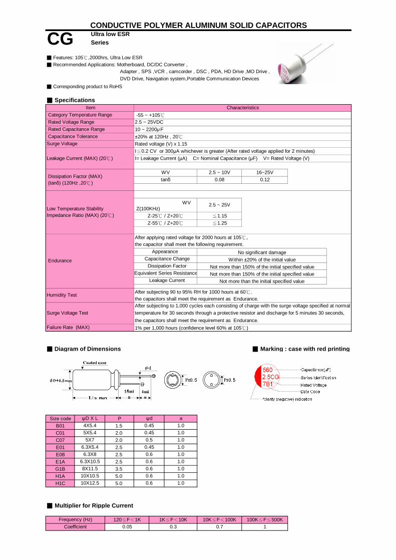
Size code PB01 1.5C01 2.0C07 2.0E01 2.5E08 2.5E1A 2.5G1B 3.5H1A 5.0H1C 5.0
1.0
4X5.4 0.450.45 1.0
1.0
the capacitor shall meet the following requirement.
2.5 ~ 10Vtanδ 0.08
Within ±20% of the initial value
Humidity Test
Leakage Current Not more than the initial specified value
≦1.15≦1.25
After subjecting to 1,000 cycles each consisting of charge with the surge voltage specified at normal
6.3X5.4 0.45
a
temperature for 30 seconds through a protective resistor and discharge for 5 minutes 30 seconds,
I≦0.2 CV or 300μA whichever is greater (After rated voltage applied for 2 minutes)
16~25V0.12
Not more than 150% of the initial specified value
■ Features: 105℃,2000hrs, Ultra Low ESR
2.5 ~ 25VDC -55 ~ +105℃
■ Specifications
Category Temperature Range Item Characteristics
DVD Drive, Navigation system,Portable Communication Devices
Capacitance Tolerance
After applying rated voltage for 2000 hours at 105℃,
Appearance
■ Recommended Applications: Motherboard, DC/DC Converter ,
Leakage Current (MAX) (20℃)
Dissipation Factor (MAX) (tanδ) (120Hz ,20℃)
Low Temperature StabilityImpedance Ratio (MAX) (20℃)
Endurance
WV
Capacitance Change
10 ~ 2200μF±20% at 120Hz , 20℃
Ultra low ESR CONDUCTIVE POLYMER ALUMINUM SOLID CAPACITORS
CG Series
Rated Voltage Range
Adapter , SPS ,VCR , camcorder , DSC , PDA, HD Drive ,MO Drive ,
Rated Capacitance Range
■ Marking : case with red printing
Surge Voltage
Equivalent Series ResistanceNot more than 150% of the initial specified value
Z-55℃ / Z+20℃Z-25℃ / Z+20℃
2.5 ~ 25V WV Z(100KHz)
Surge Voltage Test
Failure Rate (MAX)
ψd
10X12.5 0.6
1.0
5X5.45X7 0.5
6.3X8 0.6 1.0
No significant damage
Dissipation Factor
1.0
1K≦F<10K
ψD X L
Frequency (Hz)
■ Multiplier for Ripple Current
0.05100K≦F≦500K10K≦F<100K120≦F<1K
0.3Coefficient 10.7
10X10.5 0.6 1.0
6.3X10.58X11.5
0.60.6
1.01.0

RIPPLE RIPPLE RIPPLE18101810
100 1810
120 1810
180 18103500181031603500
3160 269035003500350035001810339035003190350035003190477035003390319033904200319031905600
4000 3160 35003160 4000
31904770
3160 3160 35005600 5600 4200
560056005600
750 31903160 3160 35005600 5600 4200
560050505600
5600 5600 477056005600
5600 5600 56005600 5050
56005600 5600 56005600 5050
56001800 5600 5600 56002200 5600 5600 5600
10
8X11.5
78x11.5 7 8X11.5 7
6.3X10.512
9
8X8 7
6.3X8 10560
680
6.3X6 1020
11
220
390
330
6.3X10.5
5X7
8x11.5
6.3X6
6.3x5.45X9
6.3X10.5
11
7
10X10.5
10X10.5
28
8
7
10X12.5
8X11.5
7
7
8x11.57
8x11.5 7
10X12.5
6.3X10.5
10X12.5
5X9
6.3X10.5
6.3X10.5 20
28
28
11
11
SIZE ESR
7
6.3X10.5 20
2.5V
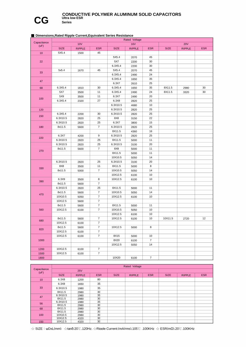
CONDUCTIVE POLYMER ALUMINUM SOLID CAPACITORS
CG Ultra low ESR Series
■ Dimensions,Rated Ripple Current,Equivalent Series Resistance
4VSIZE ESR
6.3VSIZE ESR
Capacitance(uF)
Rated Voltage
22
6.3X720
7
10
6.3X10.5
6.3X9
7
10x12.5
8x11.5
10X12.5 7 6.3X10.5
10X12.57 10X12.5
5X7
7 8x11.5
7 8x11.57
8x11.57
7
7
10X10.5 8
20
10X12.57
8x8
77
10X12.5
10X12.5
7
77
820
7
10x12.5
12008x11.5
7
10x12.5 7
6.3X10.5
8x11.5 7
10X12.5
8x11.5
470
1500
6.3X5.4 40
8X11.5 12
6.3X5.4 30
22
6.3X10.5 286.3X9
1000 78x11.58x11.5 14
10X12.5
20 6.3X10.5
6.3X5.4 30
6.3x5.4 309
86.3X9
5X9
30
1111
6.3X9
8
9
28
6.3X8 115X6 15
6.3X6 15
270 5X76.3X7
20
6.3X66.3X7
6.3X6
6.3X10.5
6.3X7
6.3X5.4 30
10X10.5 7
22
5X5.4 3047
5X9 11450
8
RIPPLE RIPPLE RIPPLE
10 1500207022002200
1670 2070249016502610
68 1810 1650 29803500 2490 33203500 24902320 2820
4680
120 28202200 28202820 31502820 38005600 2820
43604200 28202820 50002820 31005600 5000
50005050
2820 31003500 50005000 5050
61003500 610056002820 50005600 50505050 610056005600 50006100 5050
61005600 6100 272061005600 500061006100 5000
61005050
1200 61001500 61001800 6100
RIPPLE RIPPLE RIPPLE
10 12001650198029801980298019802980
68 2980298029804320
150 4320
8X11.5 30
6.3X10.5 25
6808x11.5
560
330
5X9
6.3X5.4150
5X5.4
270
6.3X10.5
10X12.5 7
10X12.5 7
7
7
8x11.5
7
8X11.5 30
6.3X5.4 305x5.4
25
45
6.3X5.4
25
6.3X10.5
9
24
11
6.3X10.5
27
6.3X5.4 30115X7
45
6.3X7
6.3X5.4 24
16
20
6.3X7
10X12.5
7
25
8x11.5
10
10X12.5 7
10X12.5 78x11.5
10
8X11.5
118X11.5
11
10X12.5
10X12.5
10X10.5 14
25
11
710
8
25
Rated Voltage20V
SIZE
10
22
11
6.3X10.5
10X12.5
8X11.5 8
25
6.3X5.4 356.3X5.4
4530
455X5.4
30
10X12.5
10X10.5
20
8X8
1420
8X11.5
ESRSIZESIZE16V
ESR
6.3X7
30
8X11.56.3X10.5
7
Capacitance(uF)
10VESR
25
8x11.5 78X8 11
6.3X10.5 25
11
390
10X10.5 7
6.3X9 8
6.3X10.5 257
4708x11.5 7 10X10.5 14
820
10X12.5 7
10
10001410X12.5
8X20
10
10X12.5 10
10X20
8X15
10X12.5
10X11.5 12
10X12.5 7 10X10.5
22 5X75X5.4
33
100
6.3X10.5
47
180
220
6.3X10.5
6.3X10.5 25
6.3X5.4 35
8X11.5
1025
15
8X11.5
8X8
6.3X10.5
6.3X8
8x11.5
6.3X10.5
6.3X7
8x11.5 7
8X11.5
8X11.5 306.3X10.5 358X11.5 30
30
☆ SIZE:ψDxL(mm) ☆tanδ:20℃,120Hz. ☆Ripple Current:(mA/rms),105℃ .100KHz ☆ ESR(mΩ).20℃.100KHz
33
56 8X11.5
6.3X86.3X10.5
6.3X10.530
35
100
47
10X12.5 30
10X10.5
SIZE ESR SIZE ESRSIZE ESR
35
10X12.53030
35
Capacitance(uF)
Rated Voltage25V
6.3X8 80
CONDUCTIVE POLYMER ALUMINUM SOLID CAPACITORS
CG Ultra low ESR Series
■ Dimensions,Rated Ripple Current,Equivalent Series Resistance
7

Adapter , SPS ,VCR , camcorder , DSC , PDA, HD Drive , MO Drive , DVD Drive, Navigation system, Portable Communication Devices
■ Corresponding product to RoHS
Rated voltage (V) x 1.15
I= Leakage Current (μA) C= Nominal Capacitance (μF) V= Rated Voltage (V)
after subjecting 90 to 95% RH for 1000 hours at 60℃.the capacitors shall meet the requirement as Endurance.
the capacitors shall meet the requirement as Endurance.1% per 1,000 hours (confidence level 60% at 105℃)
■ Diagram of Dimensions
Size code PE08 2.5G08 3.5
After subjecting to 1,000 cycles each consisting of charge with the surge voltage specified at normal
2.5 ~ 6.3V
WVtanδ
3000
2.5 ~ 25V
Not more than the initial specified value Leakage CurrentEquivalent Series Resistance
Appearance
1
Not more than 150% of the initial specified value Endurance
Humidity Test
Capacitance Change
10~25V2000
WVLife
No significant damageWithin ±20% of the initial value
Not more than 150% of the initial specified value Dissipation Factor
10 ~ 1200μF
I≦0.2 CV or 300μA whichever is greater (After rated voltage applied for 2 minutes)
±20% at 120Hz , 20℃
≦1.15≦1.25
After applying rated voltage for 3000 hours at 105℃,
Dissipation Factor (MAX) (tanδ) (120Hz ,20℃)
Low Temperature StabilityImpedance Ratio (MAX) (20℃)
Z-55℃ / Z+20℃
0.08
Rated Voltage Range
WV Z(100KHz) 2.5 ~ 25V
Rated Capacitance Range Capacitance Tolerance Surge Voltage
Leakage Current (MAX) (20℃)
8 mm height & Ultra low ESR CONDUCTIVE POLYMER ALUMINUM SOLID CAPACITORS
CP Series
■ Recommended Applications: Motherboard, DC/DC Converter ,■ Features: 105℃,3000hrs, 8mm height & Ultra Low ESR
Surge Voltage Test
■ Specifications
2.5 ~ 25VDC -55 ~ +105℃ Category Temperature Range
Item Characteristics
temperature for 30 seconds through a protective resistor and discharge for 5 minutes 30 seconds,
the capacitor shall meet the following requirement.
Z-25℃ / Z+20℃
100K≦F≦500KFrequency (Hz)
■ Marking : case with red printing
ψD X L6.3X8 0.6
0.7
1.5
0.05 0.3120≦F<1K 1K≦F<10K 10K≦F<100K
8X8 0.6
Coefficient
Failure Rate (MAX)
■ Multiplier for Ripple Current
ψd a1.0

RIPPLE RIPPLE RIPPLE42005600
4200 4200 42005600 5600 56004200 56005600
1000 56001200 5600 5600
RIPPLE RIPPLE RIPPLE10 120022 1650
16501980
47 198056 1980100 2820
2820 28202820
2820 28203500
2820 28203500 35002820 3500
50002820 35003500 5000
470 3500560 5000
35
788X8
6.3x8 80
35
25
25
6.3x8 6
25V
6.3x8 35
ESR
6.3x8
8x8 11330
8208x8 6
270
25
25
33
☆ SIZE:ψDxL(mm) ☆tanδ:20℃,120Hz. ☆Ripple Current:(mA/rms),105℃ .100KHz ☆ ESR(mΩ).20℃.100KHz
8x8
6.3x8 25
25
Capacitance(uF)
Rated Voltage10V 16V
SIZE SIZEESR
6.3x8
SIZE ESR SIZE
8x86
ESR SIZE ESR
8x8
8
5606.3x8
SIZE ESR
8x8 8
8x8 86.3x87
470
8
Capacitance(uF)
Rated Voltage2.5V
CONDUCTIVE POLYMER ALUMINUM SOLID CAPACITORS
CP 8 mm height & Ultra low ESR Series
4V 6.3V
8
35
8x8
6.3x8
7
6.3x8
8x88x8
■ Dimensions,Rated Ripple Current,Equivalent Series Resistance
6.3x8
8x8
8x8 118x8 11
2511
8x8 11
6 8x86
35
8x8 10
6.3x8 258x8
6.3x8
8x8
8x88x8
6.3x8 25
11
25
11
11
220
11
150
8x8180
6.3x8
6.3x88x8
6.3x8

Rated voltage (V) x 1.15
I= Leakage Current (μA) C= Nominal Capacitance (μF) V= Rated Voltage (V)
After subjecting 90 to 95% RH for 1000 hours at 60℃.the capacitors shall meet the requirement as Endurance.
the capacitors shall meet the requirement as Endurance.0.5% per 1,000 hours (confidence level 60% at 105℃)
■ Diagram of Dimensions
Size code PE08 2.5G08 3.5G1B 3.5H1C 5.010X12.5
ψd a
After subjecting to 1,000 cycles each consisting of charge with the surge voltage specified at normal
6.3X8 0.6 1.0
Surge Voltage Test temperature for 30 seconds through a protective resistor and discharge for 5 minutes 30 seconds,
1.0
Appearance
Equivalent Series Resistance
0.6
Not more than 150% of the initial specified value
Leakage CurrentNot more than 150% of the initial specified value
Capacitance Change Endurance
WV
Low Temperature StabilityImpedance Ratio (MAX) (20℃)
Within ±20% of the initial value
1.5
6.3 ~ 16V
Humidity Test
Not more than the initial specified value
After applying rated voltage for 2000 hours at 105℃,
≦1.15
Coefficient120≦f<1K
0.05
8X11.50.6
Rated Capacitance Range Capacitance Tolerance
Z-55℃ / Z+20℃
Dissipation Factor
Surge Voltage
10K≦f<100K0.7
8X8
Failure Rate (MAX)
■ Multiplier for Ripple Current
ψD X L
Frequency (Hz)
Category Temperature Range Item
■ Features: 105℃,2000hrs, Low ESR & large capacitance
Rated Voltage Range
100K≦f≦500K1
0.6 1.0
1K≦f<10K0.3
Characteristics
Large capacitance CY Series
CONDUCTIVE POLYMER ALUMINUM SOLID CAPACITORS
Leakage Current (MAX) (20℃)
Dissipation Factor (MAX) (tanδ) (120Hz ,20℃)
■ Recommended Applications: Used switching requlator applications in computer.
■ Specifications
Especially for high frequency.
6.3 ~16VDC -55 ~ +105℃
±20% at 120Hz , 20℃
No significant damage
150 ~ 1800μ F
6.3 ~ 16Vtanδ 0.08
I≦0.2 CV (After rated voltage applied for 2 minutes)
WV Z(100KHz)
the capacitor shall meet the following requirement.
Z-25℃ / Z+20℃≦1.25

RIPPLE RIPPLE RIPPLE150 2820180 2820220 2820 4500
3000 2820 45003000 50003000 2820 4500
50003000 4500 500030005000 4500 5600
5000680 5000 5000 5600
3000 5000 560050005600
1000 5600 56001200 5600 56001500 61001800 6100
6.3X8 30
☆ SIZE:ψDxL(mm) ☆tanδ:20℃,120Hz. ☆Ripple Current:(mA/rms),105℃ .100KHz ☆ ESR(mΩ).20℃.100KHz
270 8X8 20
30 8X8
5X7
■ Dimensions,Rated Ripple Current,Equivalent Series Resistance
Capacitance(uF)
SIZE ESR
Rated Voltage6.3V 10V 16V
30
■ Features: 105℃,2000hrs, Low ESR & large capacitance■ Recommended Applications: Used switching requlator applications in computer.
ESRSIZE ESR
8X8 20
6.3X8
12
Especially for high frequency.
Large capacitance CONDUCTIVE POLYMER ALUMINUM SOLID CAPACITORS
CY Series
SIZE
208X11.5
10X12.56.3X8 30
330 6.3X8 30 6.3X8
14
560 8X8 20 8X88X11.5
20
14
14
8X8 20 8X11.5 12 10X12.512
8206.3X9 30 8X11.5 12 10X12.5
8X11.5 12
8X11.58X11.5 10X12.5
12
10X12.512
1010
10X12.5 1010X12.5 10
30 8X8 20
12
306.3X8 30
8X11.5
6.3X8 306.3X8 30
8X11.5 12470
8X8 20
6.3X6

■ Corresponding product to RoHS
Rated voltage (V) x 1.15
I= Leakage Current (μA) C= Nominal Capacitance (μF) V= Rated Voltage (V)
after subjecting 90 to 95% RH for 1000 hours at 60℃.the capacitors shall meet the requirement as Endurance.
the capacitors shall meet the requirement as Endurance.1% per 1,000 hours (confidence level 60% at 105℃)
■ Diagram of Dimensions
Size code PB01 1.5E01 2.5E08 2.5G08 3.5G1B 3.5H1A 5.0H1C 5.0
6.3X8 0.6
Coefficient
Failure Rate (MAX)
■ Multiplier for Ripple Current
ψd a1.0
0.6
0.05 0.3 0.7
1.0
10K≦F<100K
1.0
1K≦F<10K
0.6 1.5
0.6
Frequency (Hz)
■ Marking : case with red printing
ψD X L4X5.4 0.45
8X11.58X8
120≦F<1K
10X10.510X12.5
≦1.25
the capacitor shall meet the following requirement.
100K≦F≦500K
WV Z(100KHz)
0.12tanδ
Not more than 150% of the initial specified value
After applying rated voltage for 2000 hours at 105℃,
Rated Voltage Range
WV
■ Specifications
2.5 ~ 16VDC -55 ~ +105℃ Category Temperature Range
Item Characteristics
Rated Capacitance Range Capacitance Tolerance
Small Size & Low ESR CONDUCTIVE POLYMER ALUMINUM SOLID CAPACITORS
CZ Series
■ Recommended Applications: Used switching requlator applications in computer.■ Features: 105℃,2000hrs, Low ESR
Surge Voltage
Leakage Current (MAX) (20℃)
Dissipation Factor (MAX) (tanδ) (120Hz ,20℃)
Z-25℃ / Z+20℃
2.5 ~ 16V
≦1.15
2.5 ~ 16V
After subjecting to 1,000 cycles each consisting of charge with the surge voltage specified at normal
Endurance
Humidity Test
Capacitance Change
Surge Voltage Test temperature for 30 seconds through a protective resistor and discharge for 5 minutes 30 seconds,
Not more than the initial specified value Leakage CurrentEquivalent Series Resistance
1
Not more than 150% of the initial specified value Dissipation Factor
Z-55℃ / Z+20℃
1.0
0.45 1.0
Appearance No significant damage
Especially for high frequency.
0.6 1.0
6.3X5.4
Low Temperature StabilityImpedance Ratio (MAX) (20℃)
100 ~ 2200μ F
I≦0.2 CV or 300μA whichever is greater (After rated voltage applied for 2 minutes)
±20% at 120Hz , 20℃
Within ±20% of the initial value

RIPPLE RIPPLE RIPPLE100 4700220 1810270 3500330 4700
470028205000
5000 5000 47005600 5600 5000
680 5600 48405000 5600 56005600 560056005600 5600 50005600 5600 56005600 5600 56005600 5600 5600
56001500 5600 5600 56001800 5600 5600 56002200 5600 5600
RIPPLE RIPPLE18102820
150 1810 2820180 2820
2820 28205000 450044002820 4500
50004400
2820 45005000
4500 50005000 44004500 56005000
680 5000 5600820 5000 5600
1000 56001200 5600
10
1006.3x5.4
10
80ESR
8x11.5 12
8x8 14
8x11.5 12
8x8
18
12
14
12
SIZE
356.3x8
8X8 20
6.3x8
5X7
6.3X10.5
6.3x5.4
6.3x8
CONDUCTIVE POLYMER ALUMINUM SOLID CAPACITORS
CZ Small Size & Low ESR Series
SIZE
6.3x8
■ Dimensions,Rated Ripple Current,Equivalent Series Resistance
6.3x8
6.3x8 18
8x8 14
Capacitance(uF)
ESR
8x8 14
8x11.5 128x8 14
14 8x11.5
10X10.5
6.3X10.5
10X12.5 10
8X8
14
Rated Voltage2.5V 4V 6.3V
SIZE
6.3X5.4
10V 16V
SIZE ESR SIZE ESR
6.3X8 208X8
ESR
☆ SIZE:ψDxL(mm) ☆tanδ:20℃,120Hz. ☆Ripple Current:(mA/rms),105℃ .100KHz ☆ ESR(mΩ).20℃.100KHz
8x11.5 12
Capacitance(uF)
Rated Voltage
5608x8 14
8206.3x8 188x8 14
18
8x11.5
10x12.5
10008x8 14
8x11.5 12
8x11.5 12
10x12.5 1010X12.5 1010x12.5 10
8x11.5 12
4706.3x8
10x12.514
10x12.5
12
8x8 14
8x8
18
18
108x11.5
8x11.5 128x8 8x11.5 12
12
10x12.5 1010x12.5 10
12
4708X11.5 12
8X8 20560
6.3X8 35
10X12.5 10
8X11.5 128X11.5 12
3306.3X8 30
27030
20 8X11.5 12
8X8
8X11.5
30
188X11.5
1820
10X10.5 1810X12.5
8X11.5 12
3580
8X11.5 12
10X12.5 1410X12.5 14
10X10.5
220
1200
6.3X8 356.3X8
188035
35
10X10.5 13
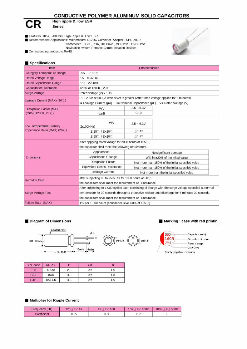
Camcorder , DSC , PDA, HD Drive , MO Drive , DVD Drive, Navigation system,Portable Communication Devices
■ Corresponding product to RoHS
Rated voltage (V) x 1.15
I= Leakage Current (μA) C= Nominal Capacitance (μF) V= Rated Voltage (V)
after subjecting 90 to 95% RH for 1000 hours at 60℃.the capacitors shall meet the requirement as Endurance.
the capacitors shall meet the requirement as Endurance.1% per 1,000 hours (confidence level 60% at 105℃)
■ Diagram of Dimensions
Size code PE08 2.5G08 3.5G1B 3.5
10K≦F<100K 100K≦F≦500KCoefficient 0.05 0.3 0.7 1
Frequency (Hz) 120≦F<1K 1K≦F<10K
■ Multiplier for Ripple Current
ψD X L ψd
8X8 0.66.3X8 0.6
Failure Rate (MAX)
Within ±20% of the initial value
the capacitor shall meet the following requirement.
Dissipation Factor
Surge Voltage Test
8X11.5 0.6 1.0
Equivalent Series Resistance
1.0
Item Characteristics
Rated Voltage Range 2.5 ~ 6.3VDC -55 ~ +105℃
1.5
a
Dissipation Factor (MAX) (tanδ) (120Hz ,20℃)
WV
High ripple & low ESR CONDUCTIVE POLYMER ALUMINUM SOLID CAPACITORS
CR Series
Rated Capacitance Range
■ Recommended Applications: Motherboard, DC/DC Converter ,Adapter , SPS ,VCR ,■ Features: 105℃,2000hrs, High Ripple & Low ESR
■ Specifications
Category Temperature Range
Capacitance ToleranceSurge Voltage
Leakage Current (MAX) (20℃)
270 ~ 2700μF
I≦0.2 CV or 500μA whichever is greater (After rated voltage applied for 2 minutes)
±20% at 120Hz , 20℃
≦1.25
0.10
Z-55℃ / Z+20℃
Not more than 150% of the initial specified value
Capacitance Change
WV Z(100KHz)
temperature for 30 seconds through a protective resistor and discharge for 5 minutes 30 seconds,
Not more than 150% of the initial specified valueNot more than the initial specified value Leakage Current
After subjecting to 1,000 cycles each consisting of charge with the surge voltage specified at normal
2.5 ~ 6.3V
tanδ
≦1.15
Low Temperature StabilityImpedance Ratio (MAX) (20℃) Z-25℃ / Z+20℃
2.5 ~ 6.3V
■ Marking : case with red printing
Endurance
Humidity Test
After applying rated voltage for 2000 hours at 105℃,
Appearance No significant damage
L+a max
Coated case
15min 4min
ψd
ψD 5.0+ xam P±0.5 P±0.5

RIPPLE RIPPLE RIPPLE
270 4700
330 4700
390 4700
4700
4700
5700
5000 5000 4700
6100 6100 5700
6100
6100 6100 4700
6100 6100 5700
5700
4800
6100
5000 6100 5700
6100 5700
6100 5700
6100
6100 6100 5700
6100 6100 5700
6100 6100
6100 6100 5700
6100 6100
6100 6100 5700
5560
1800 6500
2700 5560
8
8X11.5 7
7
8X8 7
8X11.5 7
8X8
15007
7
6.3X8 8
6.3X8 8
8X11.5 7 8X11.5
1000
12007
10X12.5
7
8X11.5
8X8
8X8 7
8X11.5 9
8X11.57
7
8X11.5 7
8X8 7
8X8
6.3X8 7
6.3X8 7
8X8 8
7
8X11.5
10X12.5 10
7
6
7
8X8
7
10X12.5 7
10X12.5 8
8X11.5 7 8X11.5
8X8
8X8 8
8X11.5 7
7
8
8
7
SIZE ESR
8X8 8
6.3X7 8
6.3X8 8
6.3X8 8
■ Dimensions,Rated Ripple Current,Equivalent Series Resistance
Capacitance(uF)
Rated Voltage
2.5V 4V 6.3V
SIZE ESR SIZE ESR
CONDUCTIVE POLYMER ALUMINUM SOLID CAPACITORS
CR High ripple & low ESR Series
470
820
560
8X11.5 7
8X11.5
680
8X8
6.3X8 8
8X8 8X7 8
10X12.5 7
6.3X8 7
☆ SIZE:ψDxL(mm) ☆tanδ:20℃,120Hz. ☆Ripple Current:(mA/rms),105℃ .100KHz ☆ ESR(mΩ).20℃.100KHz
8X11.5 7
7
10X12.5
6.3X10.5 8
8X8 7
8X11.5 8x8
6.3X8
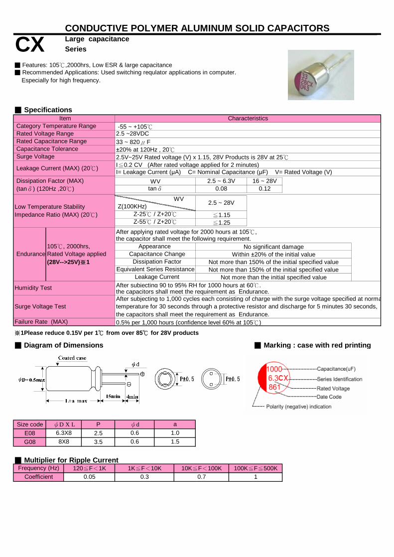
I= Leakage Current (μA) C= Nominal Capacitance (μF) V= Rated Voltage (V)
After subjecting 90 to 95% RH for 1000 hours at 60℃.the capacitors shall meet the requirement as Endurance.
the capacitors shall meet the requirement as Endurance.0.5% per 1,000 hours (confidence level 60% at 105℃)
■ Diagram of Dimensions
Size code PE08 2.5G08 3.5
WV 2.5 ~ 6.3V
0.05Frequency (Hz) 120≦F<1K 1K≦F<10K
Z-25℃ / Z+20℃
2.5 ~ 28V
Failure Rate (MAX)
■ Multiplier for Ripple Current
ψdψD X L
6.3X8 0.6
Coefficient
Large capacitance CONDUCTIVE POLYMER ALUMINUM SOLID CAPACITORS
CX Series
Rated Voltage Range
No significant damageWithin ±20% of the initial value
Z-55℃ / Z+20℃
Low Temperature StabilityImpedance Ratio (MAX) (20℃)
Appearance the capacitor shall meet the following requirement.After applying rated voltage for 2000 hours at 105℃,
WV Z(100KHz)
tanδ 0.08
■ Recommended Applications: Used switching requlator applications in computer.■ Features: 105℃,2000hrs, Low ESR & large capacitance
■ Specifications
2.5 ~28VDC -55 ~ +105℃ Category Temperature Range
Item Characteristics
Leakage CurrentEquivalent Series Resistance
≦1.15≦1.25
Leakage Current (MAX) (20℃)
33 ~ 820μF±20% at 120Hz , 20℃
Dissipation Factor (MAX) (tanδ) (120Hz ,20℃)
16 ~ 28V
After subjecting to 1,000 cycles each consisting of charge with the surge voltage specified at normal
■ Marking : case with red printing
0.12
I≦0.2 CV (After rated voltage applied for 2 minutes)
8X8 0.6 1.5
Not more than 150% of the initial specified value Dissipation Factor
Not more than the initial specified value
Capacitance Change
Rated Capacitance Range
Surge Voltage Test
a1.0
10.70.3100K≦F≦500K10K≦F<100K
Capacitance Tolerance Surge Voltage
※1Please reduce 0.15V per 1℃ from over 85℃ for 28V products
temperature for 30 seconds through a protective resistor and discharge for 5 minutes 30 seconds,
Humidity Test
Especially for high frequency.
2.5V~25V Rated voltage (V) x 1.15, 28V Products is 28V at 25℃
Endurance105℃, 2000hrs,Rated Voltage applied(28V-->25V)※1
Not more than 150% of the initial specified value
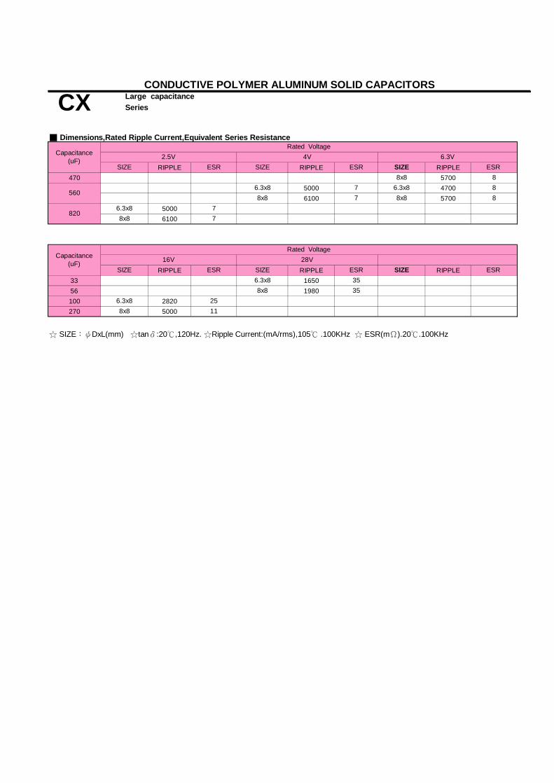
RIPPLE RIPPLE RIPPLE470 5700
5000 47006100 5700
50006100
RIPPLE RIPPLE RIPPLE33 165056 1980100 2820270 5000
6.3x8 25
5606.3x8
8206.3x8
CONDUCTIVE POLYMER ALUMINUM SOLID CAPACITORS
CX Large capacitance Series
■ Dimensions,Rated Ripple Current,Equivalent Series Resistance
Capacitance(uF)
Rated Voltage2.5V 4V 6.3V
SIZE
8x8 7
8x8 8
8x8 86.3x8 87
☆ SIZE:ψDxL(mm) ☆tanδ:20℃,120Hz. ☆Ripple Current:(mA/rms),105℃ .100KHz ☆ ESR(mΩ).20℃.100KHz
SIZE
8x8 11
SIZE ESR ESR
35
SIZE ESR 356.3x8
8x8
ESR
8x8 7
SIZE ESR SIZE ESR
7
Capacitance(uF)
Rated Voltage16V 28V

Adapter , SPS ,VCR , camcorder , DSC , PDA, HD Drive , MO Drive , DVD Drive, Navigation system, Portable Communication Devices
■ Corresponding product to RoHS
Rated voltage (V) x 1.15
After subjecting 90 to 95% RH for 1000 hours at 60℃.the capacitors shall meet the requirement as Endurance.
the capacitors shall meet the requirement as Endurance.0.5% per 1,000 hours (confidence level 60% at 105℃)
■ Diagram of Dimensions
Size code PC09 2E08 2.5E1A 2.5G08 3.5G10 3.5G1B 3.5G15 3.5H1A 5.0H1C 5.0H20 5.0
1.5
■ Multiplier for Ripple Current
1.010X12.5
8X15 0.6 1.510X10.5
10X20 0.6 1.5
8X8
0.6 1.0
0.60.68X10
1.0
10.3 0.7Coefficient120≦F<1K
0.05100K≦F≦500K10K≦F<100K
Failure Rate (MAX)
ψd
0.6
1K≦F<10KFrequency (Hz)
6.3X8
8X11.5
0.6
ψD X L
■ Features: 105℃,2000hrs, Super Low ESR & large capacitance
WV Z(100KHz)
■ Specifications
2.5 ~63VDC -55 ~ +105℃
Item Characteristics
Leakage Current (MAX) (20℃)
±20% at 120Hz , 20℃
12 ~ 64V
Rated Voltage Range
No significant damage
0.12tanδ 0.08 Dissipation Factor (MAX) (tanδ) (120Hz ,20℃)
Low Temperature StabilityImpedance Ratio (MAX) (20℃)
Capacitance Tolerance Surge Voltage
I≦0.2 CV or 300μA whichever is greater (After rated voltage applied for 2 minutes)
Large capacitance CONDUCTIVE POLYMER ALUMINUM SOLID CAPACITORS
CF Series
Rated Capacitance Range
■ Recommended Applications: Motherboard, DC/DC Converter ,
Category Temperature Range
10~ 2000μF
≦1.15
After applying rated voltage for 2000 hours at 105℃,
Z-25℃ / Z+20℃≦1.25
6.3 ~ 63V
Z-55℃ / Z+20℃
WV 2.5 ~ 10V
Not more than 150% of the initial specified value
Humidity Test
Surge Voltage TestAfter subjecting to 1,000 cycles each consisting of charge with the surge voltage specified at normal
Endurance
the capacitor shall meet the following requirement.
Capacitance Change
temperature for 30 seconds through a protective resistor and discharge for 5 minutes 30 seconds,
0.66.3X10.5 1.0
1.05X9 0.50.6 1.0
1.5
Not more than the initial specified value Leakage Current
Not more than 150% of the initial specified value
Appearance Within ±20% of the initial value
a
■ Marking : case with red printing
Equivalent Series Resistance Dissipation Factor
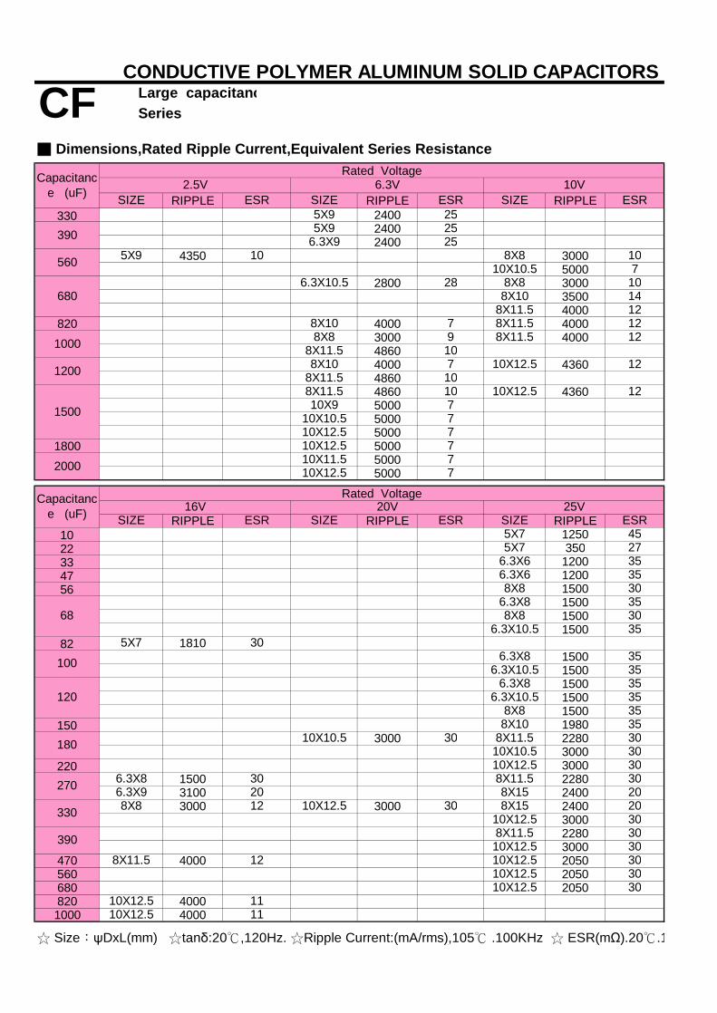
RIPPLE RIPPLE RIPPLE330 2400
24002400
4350 30005000
2800 300035004000
820 4000 40003000 400048604000 436048604860 4360500050005000
1800 500050005000
RIPPLE RIPPLE RIPPLE10 125022 35033 120047 120056 1500
150015001500
82 181015001500150015001500
150 19803000 2280
3000220 3000
1500 22803100 24003000 3000 2400
300022803000
470 4000 2050560 2050680 2050820 40001000 4000
☆ Size:ψDxL(mm) ☆tanδ:20℃,120Hz. ☆Ripple Current:(mA/rms),105℃ .100KHz ☆ ESR(mΩ).20℃.100KHz
1200
1000
8X10
8X8
CF Large capacitance Series
SIZE ESR
■ Dimensions,Rated Ripple Current,Equivalent Series Resistance
2.5V 6.3V 10V
7
8X11.5 12
7
6.3X8 30
10
255X9
10X10.5
79 8X11.5
8X11.5
ESRESR SIZESIZE
6.3X9 2525
8X8
100
25VSIZE ESR SIZE ESR SIZE ESR
30
10X10.5 30 8X11.5
30
10X12.5
8X8 358X10
3030
8X11.58X1520
30
30
10X12.5 308X11.5
30
30
3010X12.5
10X12.5
10X12.5
8X15
10X12.5
10X12.5 1110X12.5 11
390 5X9
5X9 10
710X10.5
560
8X11.5
8X828
12
7
8X10
146808X11.5
107
12
10X12.5 12
20
35
6.3X8
10X10.5
30
2000
5X7 30
7
8X11.58X11.5
1010 10X12.5
8X8
10X12.5 7
1500 10X9
10X12.5
12
10X12.510X11.5
45
16V
5X7
20V
8X10
7
270
180
308X8
35
6.3X10.5
6.3X10.5 35
35
6.3X8120
6.3X9
5X7 27
6.3X6 356.3X6 35
306.3X8 35
6.3X10.5 35
35
20330
390
68
CONDUCTIVE POLYMER ALUMINUM SOLID CAPACITORS
8X8 12 10X12.5
Rated VoltageCapacitance (uF)
Rated VoltageCapacitance (uF)
12
106.3X10.5

RIPPLE RIPPLE RIPPLE10 125015 700
990 99012002000 13002400
47 990 12005668 990 200082 1200
12001600 20001800 1760
2400120 1800150180 2400220 1800 2400270 2400330 2400390450 3000
RIPPLE33 110056 1500
☆ Size:ψDxL(mm) ☆tanδ:20℃,120Hz. ☆Ripple Current:(mA/rms),105℃ .100KHz ☆ ESR(mΩ).20℃.100KHz
8X8 65
50VESR
48
45
10X12.5 55
63VSIZE ESR
30
30
8X8
10X12.5
35
10X12.5 30
10X20
30
3525
SIZE
6.3X5.4 60
32V 35VSIZE ESR SIZE ESR
8X8 358X8
8X11.58X10 35
8X11.5 30
10X12.53030
10X12.510X10.5 30
10X12.5
8X8
8X11.5
10X12.530
100
10X12.5 30
358X840
35
6.3X8
6.3X8 40 8X8 35
6.3X8 40
8X8
40
33
6.3X8
■ Dimensions,Rated Ripple Current,Equivalent Series ResistanceRated Voltage
5X7 80
CONDUCTIVE POLYMER ALUMINUM SOLID CAPACITORS
CF Large capacitance Series
Capacitance (uF)
Rated VoltageCapacitance (uF)
22

■ Corresponding product to RoHS
Rated voltage (V) x 1.15(at room temperature or at 25℃)
After subjecting 90 to 95% RH for 1000 hours at 60℃.the capacitors shall meet the requirement as Endurance.
the capacitors shall meet the requirement as Endurance.0.5% per 1,000 hours (confidence level 60% at 105℃)
■ Diagram of Dimensions
Size code PG1B 3.5H1C 5.0
■ Multiplier for Ripple Current
Within ±20% of the initial value
■ Marking : case with red printing
100K≦F≦500K
8X11.5
Frequency (Hz)
0.6 1.00.6
1K≦F<10K 10K≦F<100KCoefficient
120≦F<1K0.05 10.3 0.7
I≦0.2 CV or 300μA whichever is greater (After rated voltage applied for 2 minutes)
25~50V
Z-55℃ / Z+20℃
WV 20 ~ 50Vtanδ 0.12
Category Temperature Range Item Characteristics
Rated Voltage Range
Humidity Test
■ Features: 105℃,2000/5000hrs & Large capacitance & Long Life & High Voltage
WV Z(100KHz)
■ Specifications
20 ~ 50VDC -55 ~ +105℃
■ Recommended Applications : LED Driver , LED Power Supply.
Large capacitance & Long Life & High VoltageCONDUCTIVE POLYMER ALUMINUM SOLID CAPACITORS
CS Series
Failure Rate (MAX)
ψd a
Leakage Current (MAX) (20℃)
±20% at 120Hz , 20℃ Rated Capacitance Range 22 ~ 470μ F
≦1.25
Capacitance Tolerance Surge Voltage
the capacitor shall meet the following requirement.
Z-25℃ / Z+20℃
Endurance
1.0
Surge Voltage Test
ψD X L
After subjecting to 1,000 cycles each consisting of charge with the surge voltage specified at normal temperature for 30 seconds through a protective resistor and discharge for 5 minutes 30 seconds,
10X12.5
Capacitance Change
Equivalent Series Resistance
Dissipation Factor (MAX) (tanδ) (120Hz ,20℃)
Low Temperature StabilityImpedance Ratio (MAX) (20℃)
No significant damage
≦1.15
After applying rated voltage for 2000/5000 hours at 105℃
Appearance
Dissipation FactorNot more than 150% of the initial specified value
Not more than the initial specified value Leakage Current
Not more than 150% of the initial specified value
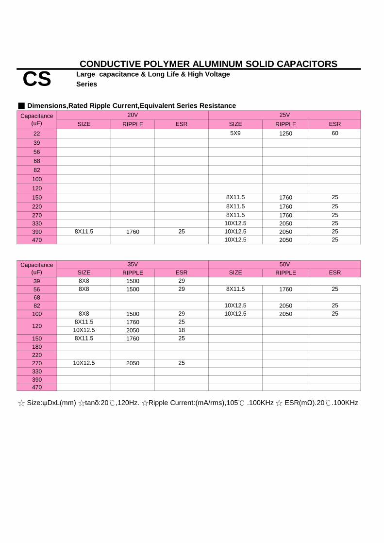
Large capacitance & Long Life & High Voltage
RIPPLE RIPPLE22 125039566882100120150 1760220 1760270 1760330 2050390 1760 2050470 2050
RIPPLE RIPPLE39 150056 1500 17606882 2050100 1500 2050
17602050
150 1760180220270 2050330390470
☆ Size:ψDxL(mm) ☆tanδ:20℃,120Hz. ☆Ripple Current:(mA/rms),105℃ .100KHz ☆ ESR(mΩ).20℃.100KHz
CONDUCTIVE POLYMER ALUMINUM SOLID CAPACITORS
CS Series
Capacitance(uF) ESR
5X9
8X8 29
258X11.5
25
Capacitance(uF)
35V 50VSIZE ESR ESR
10X12.5
ESR
■ Dimensions,Rated Ripple Current,Equivalent Series Resistance20V 25V
SIZESIZE
8X11.5
60
10X12.5
SIZE
258X11.5
25
2525
2510X12.5 2510X12.5
8X11.5 25
10X12.5 25
8X11.5 258X8 29
25 10X12.58X11.5
120
8X8 298X11.5 25
10X12.5 18

Adapter , SPS ,VCR , camcorder , DSC , PDA, HD Drive , MO Drive , DVD Drive, Navigation system, Portable Communication Devices
■ Corresponding product to RoHS
Rated voltage (V) x 1.15
I= Leakage Current (μA) C= Nominal Capacitance (μF) V= Rated Voltage (V)
after subjecting 90 to 95% RH for 1000 hours at 60℃.the capacitors shall meet the requirement as Endurance.
the capacitors shall meet the requirement as Endurance.1% per 1,000 hours (confidence level 60% at 105℃)
■ Diagram of Dimensions
Size code PC09 2.0E01 2.5E08 2.5G1B 3.5H1C 5.0
0.12
After subjecting to 1,000 cycles each consisting of charge with the surge voltage specified at normal
2.5 ~ 16V
WVtanδ
5000
Not more than 150% of the initial specified value
Z-25℃ / Z+20℃
Humidity Test
Capacitance Change
WVLife
Dissipation Factor Endurance
the capacitor shall meet the following requirement.
100 ~ 2200μ F
I≦0.2 CV or 300μA whichever is greater (After rated voltage applied for 2 minutes)
±20% at 120Hz , 20℃ Rated Capacitance Range Capacitance Tolerance Surge Voltage
Leakage Current (MAX) (20℃)
Dissipation Factor (MAX) (tanδ) (120Hz ,20℃)
Low Temperature StabilityImpedance Ratio (MAX) (20℃)
Not more than the initial specified value Leakage CurrentEquivalent Series Resistance
Appearance No significant damageWithin ±20% of the initial value
Z-55℃ / Z+20℃
Not more than 150% of the initial specified value
WV Z(100KHz) 2.5 ~ 16V
≦1.15≦1.25
After applying rated voltage for 5000 hours at 105℃,
Long life & Ultra low ESR CONDUCTIVE POLYMER ALUMINUM SOLID CAPACITORS
CH Series
Rated Voltage Range
■ Recommended Applications: Motherboard, DC/DC Converter ,■ Features: 105℃,5000hrs, Ultra Low ESR
2.5 ~ 16V
Surge Voltage Test
■ Specifications
2.5 ~ 16VDC -55 ~ +105℃ Category Temperature Range
Item Characteristics
■ Marking : case with red printing
ψD X L
6.3X8 0.66.3X5.4 0.45 1.0
100K≦F≦500KFrequency (Hz)10.05 0.3
120≦F<1K 1K≦F<10K
0.6 1.0
0.7
1.0
10K≦F<100K
10X12.5 0.6
Coefficient
8X11.5
temperature for 30 seconds through a protective resistor and discharge for 5 minutes 30 seconds,
Failure Rate (MAX)
■ Multiplier for Ripple Current
ψd a
1.0
5X9 0.5 1.0

RIPPLE RIPPLE RIPPLE
100 2320220 1700330 3500 3500
35003500
4350 3500 35003000 61003500
680 24003500 35003500
860 35001200 35001500 35001800 3500
RIPPLE RIPPLE
2490
2490180 2490220 3000
380035003500
330 3500 350035006100
560 5000 3500680 3500 3500820 4000
1000 60002200 6100
10X12.5 10
7470
6.3X5.4 3045
6.3X8 7
7
820
6.3x8560
7
8X11.5 7
10X12.5 9108x11.510
470
8X11.5 1008X11.5 10
8X8
6.3X8 7
8X11.5 10
7
ESR
2706.3X8 15
10
35
11
6.3X10.5 10
100
6.3X8 25
6.3X5.4 24
8X8
10X20 8
8X15 1110x12.5
SIZE ESR
☆ Size:ψDxL(mm) ☆tanδ:20℃,120Hz. ☆Ripple Current:(mA/rms),105℃ .100KHz ☆ ESR(mΩ).20℃.100KHz
Capacitance (uF)Rated Voltage
10V 16V
6.3x8
Capacitance (uF)Rated Voltage
2.5V 4V 6.3VSIZE ESR SIZE
CONDUCTIVE POLYMER ALUMINUM SOLID CAPACITORS
CH Long life & Ultra low ESR Series
7
6.3X5.4
6.3x8
■ Dimensions,Rated Ripple Current,Equivalent Series Resistance
10x12.5 7
ESR
8X87
8x11.5 10
8X11.5 10
78X8
6.3x86.3X5.4 16 8X8
5X9
SIZE ESR
7
108x11.5
6.3X8
SIZE
78X11.5
7
710x12.58x11.5
6.3x8 7

Camcorder , DSC , PDA, HD Drive , MO Drive , DVD Drive, Navigation system,Portable Communication Devices
■ Corresponding product to RoHS
Rated voltage (V) x 1.15
Please see the attached characteristics list
I= Leakage Current (μA) C= Nominal Capacitance (μF) V= Rated Voltage (V)
after subjecting 90 to 95% RH for 1000 hours at 60℃.the capacitors shall meet the requirement as Endurance.
the capacitors shall meet the requirement as Endurance.1% per 1,000 hours (confidence level 60% at 105℃)
■ Diagram of Dimensions
Size code PE08 2.5G08 3.5G1B 3.5H1C 5
Appearance No significant damage
Failure Rate (MAX)
the capacitor shall meet the following requirement.
Dissipation Factor
Low Temperature StabilityImpedance Ratio (MAX) (20℃) Z-25℃ / Z+20℃
6.3 ~ 25V WV Z(100KHz)
≦1.25Z-55℃ / Z+20℃
temperature for 30 seconds through a protective resistor and discharge for 5 minutes 30 seconds,
Not more than 150% of the initial specified valueNot more than the initial specified value Leakage Current
After subjecting to 1,000 cycles each consisting of charge with the surge voltage specified at normal
Within ±20% of the initial value
tanδ
Capacitance Change
0.12
±20% at 120Hz , 20℃ Capacitance ToleranceSurge Voltage
Item Characteristics
6.3 ~ 25V
Rated Capacitance Range
Leakage Current (MAX) (20℃)I≦0.2 CV or 300μA whichever is greater (After rated voltage applied for 2 minutes)
■ Specifications
Category Temperature Range
10 ~ 1200μF Rated Voltage Range 6.3 ~ 25VDC
-55 ~ +125℃
125℃ 1000hrs / 105℃ 5000hrs & Low ESRCONDUCTIVE POLYMER ALUMINUM SOLID CAPACITORS
CT Series
■ Recommended Applications: Motherboard, DC/DC Converter ,Adapter , SPS ,VCR ,■ Features: 125℃,1000hrs & 105℃,5000hrs,Low ESR
1.5
a
Dissipation Factor (MAX) (tanδ) (120Hz ,20℃)
WV
Equivalent Series Resistance
≦1.15
8X8 0.66.3X8 0.6ψD X L ψd
1.0
Surge Voltage Test
Not more than 150% of the initial specified value
■ Marking : case with red printing
Endurance
Humidity Test
After applying rated voltage for 1000 hours at 125℃ & 5000 hours at 105℃ ,
1.0
■ Multiplier for Ripple Current
10X12.5 0.6 1.08X11.5 0.6
100K≦F≦500KCoefficient 0.05 0.3 0.7 1
Frequency (Hz) 120≦F<1K 1K≦F<10K 10K≦F<100K

Tx:125℃ Tx:125℃
180 537 45 300 537 45 360
220 537 45 300 810 35 440
270 810 35 340 810 35 540
810 35 416 810 35 660
1250 17 660
810 35 592 1655 13 705
1332 15 592
560 1332 15 706 1655 13 840
680 1721 12 643 1655 13 1020
820 1721 12 775
1000 1721 12 945
Tx:125℃ Tx:125℃47 458 60 300
56 598 45 300
68 598 45 300
82 512 50 300 1050 24 328
100 512 50 320 1050 24 400
570 45 384 1367 20 480
670 40 384 480
150 670 40 480 1367 20 600
180 1151 20 576
220 1151 20 704
270 1493 16 648
1150 20 1056
1493 16 792
470 1493 16 1504
1200 1890 12 3840
Tx:125℃ Tx:125℃10 458 60 30022 458 60 30033 458 60 30047 598 45 30056 598 45 30068 1050 24 34082 1050 24 410
550 45 5001050 24 5001367 20 500
120 1367 20 600150 1367 20 750220 1050 24 1100270 1367 20 1350330 840 45 1650
10X12.5 4320
8X15 4320
330
8X11.5 3320
6.3X8 1450
4720
Capacitance(uF)
330
6.3X1.5 1800 10X12.5120
10X12.5 5440
8X11.5470
1620
8X8 2560 8X8 2560
4320
8X11.5 3630
Rated Voltage25V
SIZE ESR LC(μA)(max)after 2mins
10X12.5
10X12.5
1700
10X12.5
2560
2560
5230
5440
4210
8X8 2560
4210
10X12.5
8X11.5
CONDUCTIVE POLYMER ALUMINUM SOLID CAPACITORS
CT 125℃ 1000hrs / 105℃ 5000hrs & Low ESRSeries
8X11.5 3320
6.3X8 1450
■ Dimensions,Rated Ripple Current,Equivalent Series Resistance
Capacitance(uF)
T0:105℃
6.3X8 1620 8X11.5 3320
10X12.5 5440
☆ Tx:Ambient temperature☆ SIZE:ψDxL(mm) ☆tanδ:20℃,120Hz. ☆Ripple Current:(mA/rms),105℃ .100KHz ☆ ESR(mΩ).20℃.100KHz
ESR LC(μA)(max)after 2mins
6.3X8
Capacitance(uF) RIPPLE
ESR
10X12.5
6.3V
8X8
SIZERIPPLE
T0:105℃ T0:105℃
Rated Voltage16V 20V
SIZE
6.3X8 1700
6.3X8 1700
LC(μA)(max)after 2mins
5230
5230
8X8
8X11.5 3950
2560
Rated Voltage
ESR LC(μA)(max)after 2mins ESR LC(μA)(max)
after 2minsSIZERIPPLE
1890
T0:105℃
10V
SIZE
8X8 1890
RIPPLE
6.3X8
8X8
8X8
2120
8X8
8X8
2120
ESR
8X11.5 3640
10X12.5 4320
10X12.5
LC(μA)(max)after 2mins
10X12.5 4720
8X11.5 3640
T0:105℃SIZE
RIPPLE
10X16 6000
8X8 1890
6.3X8 1450
10X12.5 4320
6.3X8
8X8 1890
8X11.5 2650
8X11.5
10X12.5 4320
8X11.5 33201006.3X10.5 1740
3320
T0:105℃
1450
4720
8X11.5 3320
RIPPLE

Adapter , SPS ,VCR , camcorder , DSC , PDA, HD Drive , MO Drive , DVD Drive, Navigation system, Portable Communication Devices
■ Corresponding product to RoHS
Rated voltage (V) x 1.15
after subjecting 90 to 95% RH for 1000 hours at 60℃.the capacitors shall meet the requirement as Endurance.
■ Diagram of Dimensions
ΦD L A H I W P+0.15
-0.2+0.15
-0.2+0.15
-0.2+0.15
-0.28 10.4 8.3 10.0 Max 3.4 0.90±0.2 3.1±0.2
10 10.0 10.3 12.0 Max 3.5 0.90±0.2 4.6±0.210 12.2 10.3 12.0 Max 3.5 0.90±0.2 4.6±0.2
■ Multiplier for Ripple Current
K
Voltage treatment: Applying DC rated voltage to the capacitors for 2 hours at 105 oC.
6.3 7.7
Resistance to Soldering Heat*
Capacitance Change Within ±10% of the initial value Dissipation Factor Not more than 130% of the initial specified value
Equivalent Series Resistance Not more than 130% of the initial specified value Leakage Current Not more than the initial specified value
*For any doubt about measured values, measure the leakage current again after the following voltage treatment.
5
6.3
0.70±0.20
0.35
0.35
8 6.7 8.3 9.5 Max
5.8
0.70±0.20
2.6 0.350.65±0.15
3.4 0.65±0.15 2.2±0.2 0.35
1.8±0.2
5.3 6.5 Max 2.2
0.70±0.20
6.6 7.8 Max
0.65±0.15 1.5±0.2
Coefficient100K≦F≦500KFrequency (Hz) 10K≦F<100K1K≦F<10K120≦F<1K
10.70.05 0.3
■ Recommended Applications: Motherboard, DC/DC Converter ,■ Features: 105℃,2000hrs, Standard SMD type product
2.5 ~ 25V
■ Specifications
2.5 ~ 25VDC -55 ~ +105℃ Category Temperature Range
Item Characteristics
Rated Voltage Range
Standard SMD type productSURFACE MOUNT CONDUCTIVE POLYMER ALUMINUM SOLID CAPACITORS
VP
Endurance
22 ~ 1500μF±20% at 120Hz , 20℃
Rated Capacitance Range Capacitance Tolerance Surge Voltage
Leakage Current (MAX) (20℃)* Less than or equal to the value of Table.(After rated voltage applied for 2 minutes at 20℃)
Dissipation Factor (MAX) (tanδ) (120Hz ,20℃)
Low Temperature StabilityImpedance Ratio (MAX) (20℃)
Z-55℃ / Z+20℃
WV Z(100KHz)
Z-25℃ / Z+20℃
Humidity Test
Capacitance Change
WVLife
Within ±20% of the initial value
tanδ
2000
≦1.25After applying rated voltage for 2000 hours at 105℃, the capacitor shall meet the following requirement.
Not more than the initial specified value Leakage CurrentEquivalent Series Resistance
2.5 ~ 25V
≦1.15
5.8 1.8±0.26.6 7.8 Max 2.6 0.65±0.15
0.12
2.5 ~ 25V
Not more than 150% of the initial specified value
Appearance No significant damage
Not more than 150% of the initial specified value Dissipation Factor
WV

RIPPLE SIZE ESR LC(μA max/2min)100 6.3x5.8 26 300120 5x5.8 30 300150 6.3x5.8 26 300180 2200220 2500330 6.3x7.7 25 300390 2720470 2720560 2720 8x10.4 18 448
8x10.4 18 65610x12.2 10 656
1000 39504000 10x10.0 12 960
10x12.2 10 96040005500
RIPPLE SIZE ESR LC(μA max/2min)22 1380 5x5.8 40 30033 5x5.8 40 300
1380 5x5.8 40 3006.3x5.8 31 300
56 6.3x5.8 31 30068 240082 2400
1380 6.3X5.8 31 3002400 6.3X7.7 27 3002400 6.3X7.7 27 300
8X6.7 27 300150 6.3x7.7 27 300
2400 8X6.7 21 44026503020
270 265024002650
390 8x10.4 22 7802650 10x10.0 14 9403610 10x12.2 12 940
560 10x12.2 12 1120361036505500361036505500
1000 3610 10x12.2 13 2000
330
10x10.0 12 1033
5300
6.3x7.7 25 300
8X6.7 23 300
6.3x5.8
5X5.8 35 300
6.3x5.8
47
100
2727
280027 300
120
5500
300
300
4000500
300
750
820
SURFACE MOUNT CONDUCTIVE POLYMER ALUMINUM SOLID CAPACITORS
VP Standard SMD type product
■ Dimensions,Rated Ripple Current,Equivalent Series Resistance
LC(μA max/2min)
Capacitance (μF)
4VSIZE
Rated Voltage
6.3x5.8 25
RIPPLE2.5V
ESR
2650
6.3x5.8 25 300
39503950
6.3x7.7 236.3x7.7 23 300
8x10.4 18600
300
2450
5500
14902450
Capacitance (μF)
6.3V 10VSIZE ESR LC(μA max/2min)
Rated Voltage
RIPPLE
8X6.7
6.3x5.8 3005x5.8
27 3006.3x5.835
750
1270
35003020
25 300
416
3220
120010x10.0 12
10x12.2 1010x10.0 12
1500
☆ SIZE:ψDxL(mm) ☆tanδ:20℃,120Hz. ☆Ripple Current:(mA/rms),105℃ .100KHz ☆ ESR(mΩ).20℃.100KHz
1270
10x12.2
25 340
2560
2250
225025602560
4706.3X7.7 25 592
21 5928X10.4
12705x5.8 35 3002250
6808x10.4 21 85710x10.0 12 857
10 857
8208X10.4 21 1033
10x12.2 10 1033
220
6.3x7.7 25 416
6.3x5.8 27 300
6.3x7.76.3X5.8 270
5300
8X10.4 21 1260 4800

RIPPLE SIZE ESR LC(μA max/2min)22 1210 6.3X5.8 50 30033 2050 8X6.7 45 30039 2050
1600 6.3X7.7 45 3008X6.7 45 300
24202700
100 2420 8X10.4 24 400120 2420150 3490180 3490
34905050
270 349031005050
390 300031005050
560 5050680 5050820 5050
RIPPLE27 127033 25003947 1800
100 3320180
3800
270
680
476.3x5.8 50 300 2000
10X12.2 14 1056
8X10.4
470
10X12.2 14 1792
10x10.0 16 150410X12.2 14 1056
480576
320
826.3x7.7 30 3008X6.7
105614
8641056
704
14 2624
10x10.0
23 1248
☆ SIZE:ψDxL(mm) ☆tanδ:20℃,120Hz. ☆Ripple Current:(mA/rms),105℃ .100KHz ☆ ESR(mΩ).20℃.100KHz
1900
8x10.4 23704
10X12.2
1650
300
30 332030 300
320
1900
Capacitance (μF)
16V 20VSIZE ESR LC(μA max/2min) RIPPLE
■ Dimensions,Rated Ripple Current,Equivalent Series Resistance
Rated Voltage
6.3x5.8
90 3005x5.86.3x5.8 37 300
37
SURFACE MOUNT CONDUCTIVE POLYMER ALUMINUM SOLID CAPACITORS
VP Standard SMD type product
33016
8x10.4 23
10x12.2
2208x10.4 23
6.3x7.7
10x12.2 14
8X10.4 236.3X7.7 30
Capacitance (μF)
Rated Voltage25V
SIZE ESR LC(μA max/2min)6.3X5.8 60 3008X10.4 30 300
6.3X7.7 45 3008X10.4 24 500
220 10X12.2 28 1100
330

Adapter , SPS ,VCR , camcorder , DSC , PDA, HD Drive , MO Drive , DVD Drive, Navigation system, Portable Communication Devices
■ Corresponding product to RoHS
Rated voltage (V) x 1.15
after subjecting 90 to 95% RH for 1000 hours at 60℃.the capacitors shall meet the requirement as Endurance.
■ Diagram of Dimensions
ΦD L A H I W P+0.15
-0.2+0.15
-0.2+0.15
-0.28 10.4 8.3 10.0 Max 3.4 0.90±0.2 3.1±0.2
10 10.0 10.3 12.0 Max 3.5 0.90±0.2 4.6±0.2
■ Multiplier for Ripple Current
8.3 9.5 Max
2.6 0.65±0.15
0.70±0.200.70±0.20
3.4 0.65±0.15 2.2±0.2 0.35
1.8±0.2 0.356.3 7.7 6.6 7.8 Max
2.5 ~ 25V
WVtanδ
2000
≦1.25After applying rated voltage for 2000 hours at 105℃, the capacitor shall meet the following requirement.
1
Not more than 150% of the initial specified value Endurance
Humidity Test
Capacitance Change
WVLife
Not more than the initial specified value Leakage CurrentEquivalent Series Resistance
Appearance No significant damageWithin ±20% of the initial value
Not more than 150% of the initial specified value Dissipation Factor
Z-55℃ / Z+20℃
33 ~ 1200μF±20% at 120Hz , 20℃
Rated Capacitance Range Capacitance Tolerance Surge Voltage
Leakage Current (MAX) (20℃) Less than or equal to the value of Table.(After rated voltage applied for 2 minutes at 20℃)
Z-25℃ / Z+20℃
2.5 ~ 25V
≦1.15
High capacitance and Super low ESRSURFACE MOUNT CONDUCTIVE POLYMER ALUMINUM SOLID CAPACITORS
VB
Dissipation Factor (MAX) (tanδ) (120Hz ,20℃)
Low Temperature StabilityImpedance Ratio (MAX) (20℃)
Category Temperature Range Item Characteristics
Rated Voltage Range
WV Z(100KHz)
0.12
0.70.05 0.3Coefficient
■ Recommended Applications: Motherboard, DC/DC Converter ,■ Features: 105℃,2000hrs, High capacitance and Super low ESR
2.5 ~ 25V
■ Specifications
2.5 ~ 25VDC -55 ~ +105℃
6.6 7.8 Max 2.6
100K≦F≦500KFrequency (Hz) 10K≦F<100K1K≦F<10K120≦F<1K
8 6.7
Resistance to Soldering Heat* Equivalent Series Resistance Not more than 130% of the initial specified value
Capacitance Change
6.3 0.350.65±0.15 1.8±0.25.8
Within ±10% of the initial value Dissipation Factor Not more than 130% of the initial specified value
Leakage Current Not more than the initial specified value
K
*For any doubt about measured values, measure the leakage current again after the following voltage treatment. Voltage treatment: Applying DC rated voltage to the capacitors for 2 hours at 105 oC.

RIPPLE SIZE ESR LC(μA max/2min)220270 6.3x5.8 15 300330 3160 6.3x5.8 15 300390 3160470 3160
35003600 8X6.7 22 3004100
820 4210
RIPPLE SIZE ESR LC(μA max/2min)68 5X5.8 30 300
100 2500120 2500 6.3x5.8 22 300150 3160 6.3x7.7 21 300220 3160 8X6.7 22 540270 8X6.7 22 540
3390 8X10.4 17 660347039504210395042103470 10x10 12 940322042104210502542105025
1200 5025
RIPPLE SIZE ESR LC(μA max/2min)33 6.3X7.7 45 30047 6.3X7.7 45 300
2440270024402700322032203890
220 3890270 3890330 4350470 6100
2500300
68
2500
8X10.4 18 86410X10 16 1056
8X10.4 18 704576
8X6.7 25 576
100
6.3X7.7 22 576180
6.3X7.7 24 320
8X10.4 18
1970
820
8X10.4 15 705560
8X10.4 15
470 8X6.7 22 592
10X10 12
6.3X7.7 14 592
103310X10 12
5025
390
8X6.7 22 415
6.3X5.8 15 300
2880
560
6.3X5.8 24 300
8X6.7 13 300
SIZE ESR LC(μA max/2min)
6.3x5.8 15 300
6.3x5.8 16 300300
8X10.4 15 592
3220
RIPPLE
13 300 3220
Rated Voltage
6.3X7.7
300
25V
26006.3x5.8
8X6.7 22 491
6.3x5.8
ESR LC(μA max/2min)
12
8X10.4 15 491
25
SIZE
1033
330
17 415 40006.3X7.7 14 4156.3x5.8
8X10.4
10X12.2 10
24 3006.3X7.76.3x5.8 25 300
1504
3220
24
705
15
Rated Voltage2.5VESR LC(μA max/2min)
Capacitance (μF)
10X10 1510
8X10.4 12 410
Capacitance (μF)
Capacitance (μF)
6.3V 10V
SURFACE MOUNT CONDUCTIVE POLYMER ALUMINUM SOLID CAPACITORS
VB High capacitance and Super low ESR
■ Dimensions,Rated Ripple Current,Equivalent Series Resistance
☆ SIZE:ψDxL(mm) ☆tanδ:20℃,120Hz. ☆Ripple Current:(mA/rms),105℃ .100KHz ☆ ESR(mΩ).20℃.100KHz
RIPPLE
Rated Voltage16V
6.3X5.8
6.3X5.8
15 300 3160
4VSIZE
6.3X5.8 15 300
RIPPLE
15
3160

Adapter , SPS ,VCR , camcorder , DSC , PDA, HD Drive , MO Drive , DVD Drive, Navigation system, Portable Communication Devices
■ Corresponding product to RoHS
Rated voltage (V) x 1.15
after subjecting 90 to 95% RH for 1000 hours at 60℃.the capacitors shall meet the requirement as Endurance.
■ Diagram of Dimensions
ΦD L A H I W P+0.15-0.2
■ Multiplier for Ripple Current
Leakage Current
Voltage treatment: Applying DC rated voltage to the capacitors for 2 hours at 105 oC.
Less than or equal to the value of Table.(After rated voltage applied for 2 minutes at 20℃ )
Not more than the initial specified value*For any doubt about measured values, measure the leakage current again after the following voltage treatment.
Resistance to Soldering Heat*
Within ±10% of the initial value Dissipation Factor Not more than 130% of the initial specified value
Equivalent Series Resistance
0.12
2.5 ~ 16V
WV
Not more than 130% of the initial specified value
5000
≦1.25After applying rated voltage for 5000 hours at 105℃, the capacitor shall meet the following requirement.
1
Not more than 150% of the initial specified valueEquivalent Series Resistance
Appearance No significant damageWithin ±20% of the initial value
Capacitance Change
Not more than 150% of the initial specified value Endurance
Humidity Test
Capacitance Change
WVLife
Not more than the initial specified value Leakage Current
Dissipation Factor
Dissipation Factor (MAX) (tanδ) (120Hz ,20℃)
Low Temperature StabilityImpedance Ratio (MAX) (20℃)
Z-55℃ / Z+20℃
22 ~ 470μF
Leakage Current (MAX) (20℃)
±20% at 120Hz , 20℃ Rated Capacitance Range Capacitance Tolerance Surge Voltage
WV Z(100KHz)
Z-25℃ / Z+20℃
4 ~ 16V
≦1.15
4 ~ 16Vtanδ
Long life and Ultra low ESRSURFACE MOUNT CONDUCTIVE POLYMER ALUMINUM SOLID CAPACITORS
VS■ Recommended Applications: Motherboard, DC/DC Converter ,■ Features: 105℃,5000hrs, Long life and Ultra low ESR
■ Specifications
4 ~ 20VDC -55 ~ +105℃ Category Temperature Range
Item Characteristics
Rated Voltage Range
10.4 8.3
0.70.05 0.3Coefficient
6.3 0.350.65±0.15 1.8±0.2
100K≦F≦500KFrequency (Hz) 10K≦F<100K1K≦F<10K120≦F<1K
8
10 12.2 10.3 12.0Max 3.5
K
5.8 6.6 7.8 Max 2.6
0.90±0.2 4.6±0.2 0.70±0.20
10.0Max 3.4 0.90±0.2 3.1±0.2 0.70±0.20

RIPPLE SIZE ESR LC(μA max/2min)100 6.3x5.8 22 300120 6.3x5.8 22 300150 2570
6.3x5.8 20 3008X6.7 22 300
330 2800 6.3X5.8 20 415470 2800 10X10 20 592
RIPPLE SIZE ESR LC(μA max/2min)22 5X5.8 45 30039 6.3x5.8 30 30047 230056 230068 2300 6.3x5.8 30 300120 2300330 10x12.2 14 1056470 3000
RIPPLE27 245068180 3200470
☆ SIZE:ψDxL(mm) ☆tanδ:20℃,120Hz. ☆Ripple Current:(mA/rms),105℃ .100KHz ☆ ESR(mΩ).20℃.100KHz
2200
6.3x5.8 27 3002200
2800
4130
Capacitance(μF) 10V 16V
SIZE ESR LC(μA max/2min) RIPPLE
Rated Voltage
Capacitance(μF) 6.3V
SIZE
Rated Voltage
2800
■ Dimensions,Rated Ripple Current,Equivalent Series Resistance
RIPPLE4VESR LC(μA max/2min)
SURFACE MOUNT CONDUCTIVE POLYMER ALUMINUM SOLID CAPACITORS
VS Long life and Ultra low ESR
6.3x5.8
6.3X7.7 20 376
22
6.3x5.8 27 300
8x10.4 22 940
300
6.3x5.8 27 3003800
Capacitance(μF)
Rated Voltage20V
SIZE ESR LC(μA max/2min)6.3X5.8 40 300
10X10 25 720
2800
1060
32202800
6.3X5.8 27 300
220
6.3X5.8 20 300

Series
■Corresponding product to RoHS
■ Specifications
Capacitance Range Capacitance Tolerance
I≦0.01CV or 3(μA) , whichever is greater. (After rated voltage applied for 2 minutes )
I= Leakage Current (μA) C= Nominal Capacitance (μF) V= Rated Voltage (V)
7 4 3 2 2 2 2 2 215 8 6 4 4 3 3 3 3
■ Diagram of Dimensions(mm)ψD L A H I W P
+0.15-0.20+0.15-0.20+0.15-0.20+0.15-0.20
8.0 10.2 8.3 10.0 Max 3.4 0.90±0.2 3.1±0.2( ) : Reference size 10.0 10.2 10.3 12.0 Max 3.5 0.90±0.2 4.6±0.2
■ Multiplier for Ripple CurrentFrequency coefficient
the capacitors shall meet the following requirements.
7.7 6.6 7.8 Max
1K120
Leakage Current
Within ±20% of the initial value
Not more than the specified value Dissipation Factor Not more than 200% of the specified value
60
5.4
5.4
6.3
± 20 % at 120Hz , 20℃
Impedance Ratio (MAX) Low Temperature Stability
WVZ(120HZ)
4 25
Z(-25℃) / Z(20℃)
■Recommended Applications: Suitable for AV(TV,Video,Audio),Monitor/Computer, Home appliance, OA/HA/Communication
1 ~ 1500μF
Dissipation Factor (MAX) (tanδ) (120Hz ,20℃)
Item Characteristics
-40 ~ +85℃ Rated Voltage Range (WV)
0.70±0.20
5.5 Max
7.8 Max
5.3
1.0±0.2 0.35
6.6
6.5 Max
1.8
0.70±0.20
2.2 1.5±0.2
1.8±0.2
0.35
0.35
2.6 0.65±0.1 1.8±0.2 0.35
SURFACE MOUNT ALUMINUM ELECTROLYTIC
■Features : 85℃ 2000 hours & Low profile vertical chip
GV General purpose
Shelf Life
4.0
5.0
6.3
After placed at 85℃without voltage applied for 1000 hours,the capacitor shall meet the same requirement as Endurance.
2.6
K
50 100636.3 10 16 35
4 ~ 100VDC
1.00 1.15 1.25
5.4
10K
0.65±0.1
0.65±0.1
0.65±0.1
4.3
Coefficient 0.80
Operating Temperature Range
Capacitance Change
Z(-40℃) / Z(20℃)
After applying rated voltage for 2000hrs at 85℃,
Endurance
Leakage Current (MAX) (20℃)
Shown in the table of standard rating
Frequency (Hz)
s

Size tanδ Ripple Size tanδ Ripple Size tanδ Ripple Size tanδ Ripple4.7 4x5.4 0.16 2010 4x5.4 0.16 28
4x5.4 0.26 285x5.4 0.16 39
4x5.4 0.30 29 5x5.4 0.26 455x5.4 0.20 43 6.3x5.4 0.16 66
4x5.4 0.26 36 5x5.4 0.16 455x5.4 0.26 46 6.3x5.4 0.16 705x5.4 0.26 47 6.3x5.4 0.20 70
6.3x5.4 0.26 71 6.3x7.7 0.20 856.3x5.4 0.35 74 6.3x7.7 0.20 1626.3x7.7 0.35 235 8x10.2 0.20 280
8x10.2 0.20 32010x10.2 0.20 380
8x10.2 0.26 390 8x10.2 0.20 35010x10.2 0.26 400 10x10.2 0.20 420
8x10.2 0.35 500 10x10.2 0.26 58010x10.2 0.35 700
1500 10x10.2 0.35 750
Size tanδ Ripple Size tanδ Ripple Size tanδ Ripple1 4x5.4 0.12 10
2.2 4x5.4 0.12 8 4x5.4 0.12 163.3 4x5.4 0.12 10 4x5.4 0.12 16
4x5.4 0.14 185x5.4 0.12 23
4x5.4 0.20 24 4x5.4 0.16 24 5x5.4 0.14 275x5.4 0.14 28 5x5.4 0.12 30 6.3x5.4 0.12 355x5.4 0.20 35 5x5.4 0.16 36 6.3x5.4 0.14 40
6.3x5.4 0.14 55 6.3x5.4 0.12 60 6.3x7.7 0.12 905x5.4 0.20 42 6.3x5.4 0.16 60 6.3x7.7 0.12 90
6.3x5.4 0.14 65 6.3x7.7 0.14 130 8x10.2 0.12 1206.3x5.4 0.20 70 6.3x5.4 0.16 70 6.3x7.7 0.12 906.3x7.7 0.16 96 6.3x7.7 0.14 165 8x10.2 0.12 1206.3x7.7 0.16 143 6.3x7.7 0.14 140 8x10.2 0.12 2008x10.2 0.16 180 8x10.2 0.14 180 10x10.2 0.12 2508x10.2 0.16 230 8x10.2 0.14 200
10x10.2 0.16 310 10x10.2 0.14 3108x10.2 0.16 270
10x10.2 0.16 340470 10x10.2 0.16 380
Size tanδ Ripple Size tanδ Ripple3.3 6.3x7.7 0.18 504.7 6.3x5.4 0.18 20 6.3x7.7 0.18 50
6.3x7.7 0.18 508x10.2 0.18 55
6.3x7.7 0.18 40 8x10.2 0.18 558x10.2 0.18 40 10x10.2 0.18 85
33 8x10.2 0.18 45 10x10.2 0.18 9047 8x10.2 0.18 45
100 10x10.2 0.18 60
☆Size:Dψx L(mm).☆tanδ:20℃,120Hz.☆Ripple Current: 85℃,120Hz,(mA/rms).
280
0.35 0.26 22
4x5.4 200.26
82
0.35
100
47
22
22
33
330
470
0.35 61
0.35 200
4x5.4
1000
220 6.3x5.4 0.35
22
10 6.3x5.4
Rated (Surge) VoltageCapacitance
(μF)63(79) 100(125)
80
6.3x7.7
6.3x7.7
220
330
0.18 20
6.3x5.4 0.26 70
34 5x5.4 0.30 43
33 4x5.4
10
47 4x5.4 0.35
100 5x5.4
6.3x5.4 0.35
4(5)
■Dimensions,Max Dissipation Factor,Max Permissible Ripple Current
16(20)6.3(8)
22 280.304x5.4
SURFACE MOUNT ALUMINUM ELECTROLYTIC
Rated (Surge) Voltage10(13)
General purpose SeriesGV
Capacitance
(μF)
26 4x5.4
4.7 4x5.4 0.14
Capacitance
(μF)
Rated (Surge) Voltage25(32) 35(44) 50(63)
10x10.2 0.14 350
3808x10.2 0.35
0.12 22
6.3x7.7 0.26 250
10x10.2 0.12 300
8x10.2 0.26 330

Long LifeSeries
■ Corresponding product to RoHS
■ Specifications
4 ~ 100VDC Rated Capacitance Range Capacitance Tolerance
I≦0.01CV or 3(μA) , whichever is greater. (After rated voltage applied for 2 minutes )
I= Leakage Current (μA) C= Nominal Capacitance (μF) V= Rated Voltage (V)
7 4 3 2 2 2 2 2 215 8 6 4 4 3 3 3 3
Case (ψ)ψD≦6.3ψD≧8
■ Diagram of Dimensions(mm)
ψD L A H I W P
( ) : Reference size8.0 10.2 8.3 10.0 Max 3.4 0.90±0.2 3.1±0.2
( ) : Reference size 10.0 10.2 10.3 12.0 Max 3.5 0.90±0.2 4.6±0.2
■ Multiplier for Ripple CurrentFrequency coefficient
Impedance Ratio (MAX) Low Temperature Stability
Within ±20% of the initial value
Item CharacteristicsOperating Temperature Range
■ Recommended Applications: Suitable for AV(TV,Video,Audio),Monitor/Computer, OA/HA/Communication
1 ~ 1000μF
Dissipation Factor (MAX) (tanδ) (120Hz ,20℃)
Rated Voltage Range (WV)
Leakage Current (MAX) (20℃)
-40 ~ +85℃
10K
Shelf Life
Not more than the specified value
Life time (hrs)
+0.15-0.20
+0.15-0.20
After placed at 85℃without voltage applied for 1000 hours,the capacitor shall meet the same requirement as Endurance.
Dissipation Factor 30005000
SURFACE MOUNT ALUMINUM ELECTROLYTIC
■ Features : 85℃ 3000~5000 hours,Longer life than GV, Low profile vertical chip
FV
Not move than 200% of the specified value
Z(-25℃) / Z(20℃)
± 20 % at 120Hz , 20℃
Frequency (Hz) 60 120 1K
Z(-40℃) / Z(20℃)
Shown in the table of standard rating
Leakage Current
2516
Endurance
4 WV Z(120HZ)
1.00 1.15 1.25
Capacitance Change
After applying rated voltage for 3000~5000 hours at 85℃,
0.70±0.2
Coefficient 0.80
the capacitors shall meet the following requirements.
1006.3 10 35 50 63
K
0.35
0.35
+0.15-0.20
0.70±0.2
1.0±0.20.65±0.1 0.35
0.35 +0.15-0.200.65±0.1 1.5±0.2
4.0
5.0 5.4 5.3
1.85.5 Max4.35.4
5.4 6.6 7.8 Max
6.5 Max 2.2
2.6 0.65±0.1 1.8±0.2
8.0 6.2 8.3 9.5 Max 3.4 0.65±0.1 2.2±0.2
6.3
s

SURFACE MOUNT ALUMINUM ELECTROLYTIC Long LifeSeries
Size tanδ Ripple Size tanδ Ripple Size tanδ Ripple Size tanδ Ripple4.7 4x5.4 0.16 2010 4x5.4 0.16 28
4x5.4 0.26 275x5.4 0.16 39
4x5.4 0.30 29 5x5.4 0.26 455x5.4 0.20 43 6.3x5.4 0.16 66
47 4x5.4 0.35 34 5x5.4 0.26 46 5x5.4 0.30 43 6.3x5.4 0.16 70100 5x5.4 0.35 61 6.3x5.4 0.26 71 6.3x5.4 0.26 70 6.3x5.4 0.20 70220 6.3x5.4 0.35 82 6.3x7.7 0.35 250 6.3x7.7 0.26 250 8x10.2 0.20 280330 6.3x7.7 0.35 300 8x10.2 0.26 330 10x10.2 0.20 380470 8x10.2 0.35 380 10x10.2 0.26 400 10x10.2 0.20 420
1000 10x10.2 0.35 700 10x10.2 0.26 580
Size tanδ Ripple Size tanδ Ripple Size tanδ Ripple1 4x5.4 0.12 10
2.2 4x5.4 0.12 8 4x5.4 0.12 163.3 4x5.4 0.12 10 4x5.4 0.12 164.7 4x5.4 0.14 22 4x5.4 0.12 22 5x5.4 0.12 23
4x5.4 0.20 24 4x5.4 0.16 245x5.4 0.14 28 5x5.4 0.12 30
22 6.3x5.4 0.14 55 6.3x5.4 0.12 60 6.3x7.7 0.12 11033 6.3x5.4 0.14 65 6.3x7.7 0.14 130 8x10.2 0.12 120
6.3x5.4 0.20 706.3x7.7 0.16 96
100 8x10.2 0.16 180 10x10.2 0.14 210 10x10.2 0.12 190220 10x10.2 0.16 310 10x10.2 0.14 310
Size tanδ Ripple Size tanδ Ripple3.3 8x10.2 0.18 304.7 8x10.2 0.18 25 8x10.2 0.18 8010 8x10.2 0.18 25 8x10.2 0.18 8522 8x10.2 0.18 45 10x10.2 0.18 8533 10x10.2 0.18 45 10x10.2 0.18 9047 10x10.2 0.18 55
☆Size:Dψx L(mm).☆tanδ:20℃,120Hz.☆Ripple Current: 85℃,120Hz,(mA/rms).
Capacitance
(μF)63(79) 100(125)
Rated (Surge) Voltage
47 0.14
35
1300.12
6.3x5.4
6.3x7.7 165 10x10.2
10 0.12
190.354x5.422 200.26
33 4x5.4 0.35 26 5x5.4 0.26
280.304x5.4
16(20)Rated (Surge) Voltage
4(5) 10(13)
■Dimensions,Max Dissipation Factor,Max Permissible Ripple Current
Capacitance
(μF)
FVCapacitanc
e (μF)
Rated (Surge) Voltage25(32) 35(44) 50(63)
6.3(8)
22
4x5.4
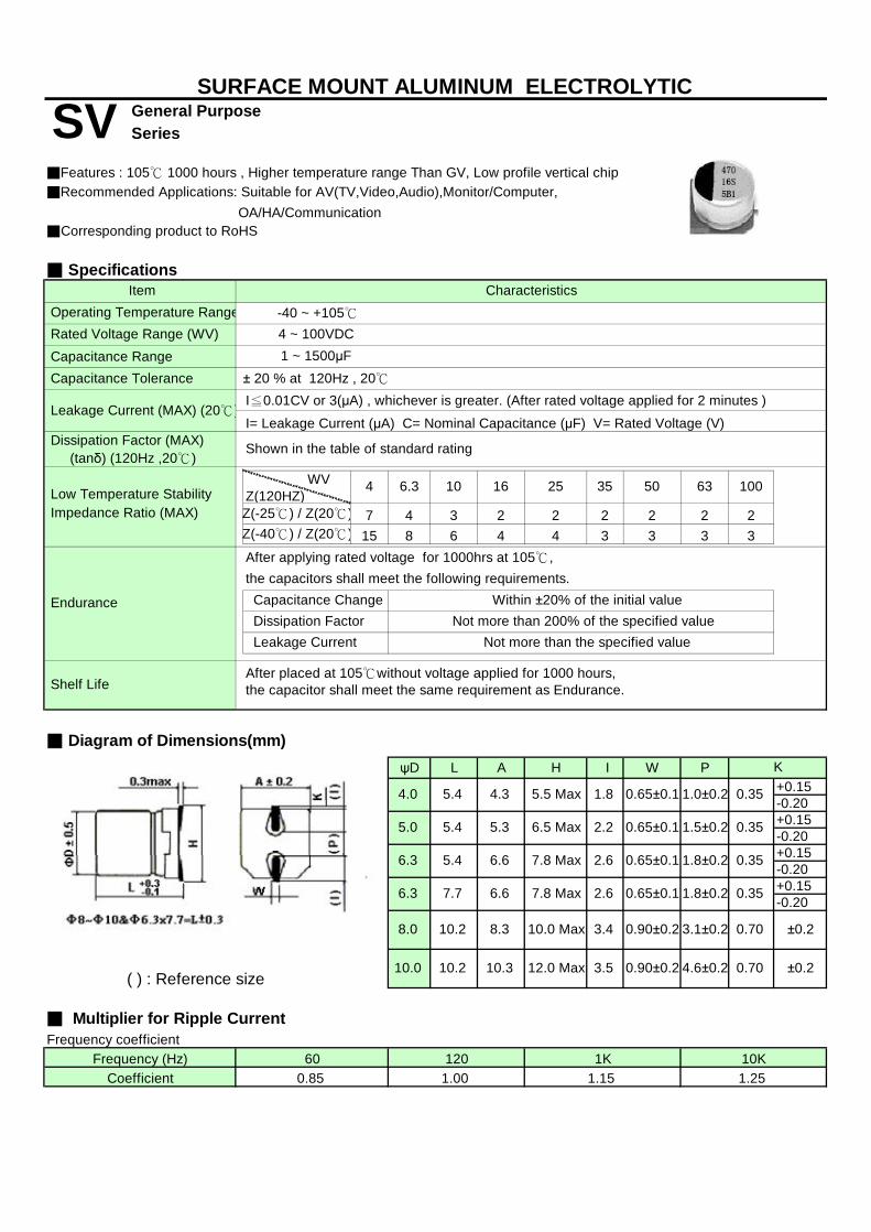
General Purpose Series
■Corresponding product to RoHS
■ Specifications
Capacitance Range Capacitance Tolerance
I≦0.01CV or 3(μA) , whichever is greater. (After rated voltage applied for 2 minutes )
I= Leakage Current (μA) C= Nominal Capacitance (μF) V= Rated Voltage (V)
7 4 3 2 2 2 2 2 215 8 6 4 4 3 3 3 3
■ Diagram of Dimensions(mm)ψD L A H I W P
+0.15-0.20+0.15-0.20+0.15-0.20+0.15-0.20
( ) : Reference size
■ Multiplier for Ripple CurrentFrequency coefficient
■Features : 105℃ 1000 hours , Higher temperature range Than GV, Low profile vertical chip
636.3 10 16 3525
Leakage Current (MAX) (20℃)
Shown in the table of standard rating
■Recommended Applications: Suitable for AV(TV,Video,Audio),Monitor/Computer,
Z(-25℃) / Z(20℃) Impedance Ratio (MAX) Low Temperature Stability
WVZ(120HZ)
Z(-40℃) / Z(20℃)
OA/HA/Communication
1 ~ 1500μF
Dissipation Factor (MAX) (tanδ) (120Hz ,20℃)
± 20 % at 120Hz , 20℃
Rated Voltage Range (WV) -40 ~ +105℃4 ~ 100VDC
1.5±0.2
0.35
4 50 100
the capacitors shall meet the following requirements.
5.5 Max
0.350.65±0.1
After placed at 105℃without voltage applied for 1000 hours,the capacitor shall meet the same requirement as Endurance.
0.352.6
0.35
1.8±0.20.65±0.1
2.6 0.65±0.1 1.8±0.2
SURFACE MOUNT ALUMINUM ELECTROLYTIC
SV
0.65±0.1
5.3
Endurance
Shelf Life
Dissipation Factor
4.3
Within ±20% of the initial value Not more than 200% of the specified value
Not more than the specified value
Frequency (Hz) 60
1.8
7.8 Max
4.0
5.0
1.0±0.2
1.15120
6.3
6.3 5.4 6.6
1K
0.90±0.2
0.90±0.2
5.4
1.00
K
10K
Leakage Current
6.67.7 7.8 Max
5.4 2.2
3.5
6.5 Max
1.25
Operating Temperature Range Item
Capacitance Change
Characteristics
After applying rated voltage for 1000hrs at 105℃,
Coefficient
8.0 10.2 8.3 10.0 Max 3.4
0.85
10.0 10.2 10.3 12.0 Max
3.1±0.2
4.6±0.2 0.70 ±0.2
±0.20.70
s
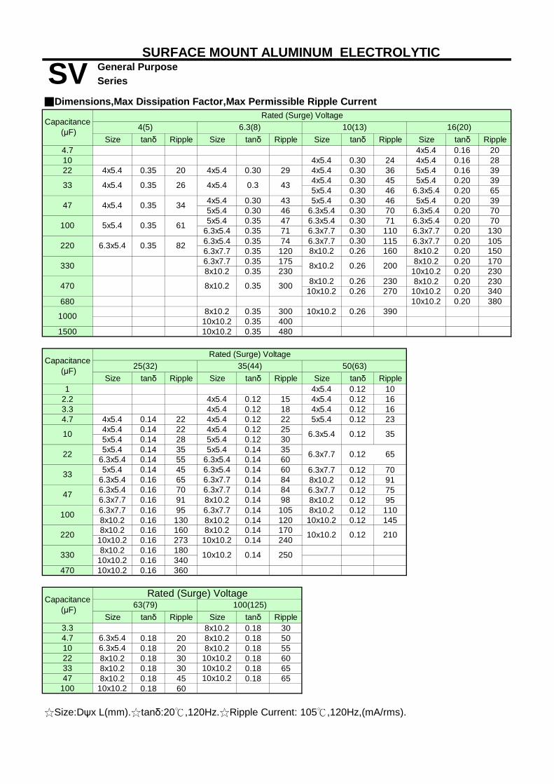
General Purpose
Size tanδ Ripple Size tanδ Ripple Size tanδ Ripple Size tanδ Ripple4.7 4x5.4 0.16 2010 4x5.4 0.30 24 4x5.4 0.16 2822 4x5.4 0.35 20 4x5.4 0.30 29 4x5.4 0.30 36 5x5.4 0.16 39
4x5.4 0.30 45 5x5.4 0.20 395x5.4 0.30 46 6.3x5.4 0.20 65
4x5.4 0.30 43 5x5.4 0.30 46 5x5.4 0.20 395x5.4 0.30 46 6.3x5.4 0.30 70 6.3x5.4 0.20 705x5.4 0.35 47 6.3x5.4 0.30 71 6.3x5.4 0.20 70
6.3x5.4 0.35 71 6.3x7.7 0.30 110 6.3x7.7 0.20 1306.3x5.4 0.35 74 6.3x7.7 0.30 115 6.3x7.7 0.20 1056.3x7.7 0.35 120 8x10.2 0.26 160 8x10.2 0.20 1506.3x7.7 0.35 175 8x10.2 0.20 1708x10.2 0.35 230 10x10.2 0.20 230
8x10.2 0.26 230 8x10.2 0.20 23010x10.2 0.26 270 10x10.2 0.20 340
680 10x10.2 0.20 3808x10.2 0.35 300 10x10.2 0.26 390
10x10.2 0.35 4001500 10x10.2 0.35 480
Size tanδ Ripple Size tanδ Ripple Size tanδ Ripple1 4x5.4 0.12 10
2.2 4x5.4 0.12 15 4x5.4 0.12 163.3 4x5.4 0.12 18 4x5.4 0.12 164.7 4x5.4 0.14 22 4x5.4 0.12 22 5x5.4 0.12 23
4x5.4 0.14 22 4x5.4 0.12 255x5.4 0.14 28 5x5.4 0.12 305x5.4 0.14 35 5x5.4 0.14 35
6.3x5.4 0.14 55 6.3x5.4 0.14 605x5.4 0.14 45 6.3x5.4 0.14 60 6.3x7.7 0.12 70
6.3x5.4 0.16 65 6.3x7.7 0.14 84 8x10.2 0.12 916.3x5.4 0.16 70 6.3x7.7 0.14 84 6.3x7.7 0.12 756.3x7.7 0.16 91 8x10.2 0.14 98 8x10.2 0.12 956.3x7.7 0.16 95 6.3x7.7 0.14 105 8x10.2 0.12 1108x10.2 0.16 130 8x10.2 0.14 120 10x10.2 0.12 1458x10.2 0.16 160 8x10.2 0.14 170
10x10.2 0.16 273 10x10.2 0.14 2408x10.2 0.16 180
10x10.2 0.16 340470 10x10.2 0.16 360
Size tanδ Ripple Size tanδ Ripple3.3 8x10.2 0.18 304.7 6.3x5.4 0.18 20 8x10.2 0.18 5010 6.3x5.4 0.18 20 8x10.2 0.18 5522 8x10.2 0.18 30 10x10.2 0.18 6033 8x10.2 0.18 30 10x10.2 0.18 6547 8x10.2 0.18 45 10x10.2 0.18 65
100 10x10.2 0.18 60
☆Size:Dψx L(mm).☆tanδ:20℃,120Hz.☆Ripple Current: 105℃,120Hz,(mA/rms).
0.12 65
100 5x5.4 0.35
470
22
6.3x5.4
35(44)
1000
33 4x5.4 0.35 26 4x5.4 0.3 43
63(79) 100(125)Capacitance (μF)
Rated (Surge) Voltage
8x10.2 0.35 300
Rated (Surge) Voltage25(32)
16(20)
SURFACE MOUNT ALUMINUM ELECTROLYTIC
Rated (Surge) Voltage■Dimensions,Max Dissipation Factor,Max Permissible Ripple Current
SeriesSVCapacitance
(μF) 4(5) 6.3(8) 10(13)
100
220
330
33
Capacitance (μF)
47
47
6.3x5.4
250
10x10.2 0.12220
330 10x10.2 0.14
210
8x10.2 0.26 200
50(63)
0.12 35
6.3x7.7
10
0.354x5.4
0.35 82
34
61

Series
■Corresponding product to RoHS
■ Specifications
-40 ~ +105℃
Rated Capacitance Range Capacitance Tolerance
I≦0.01CV or 3(μA) , whichever is greater. (After rated voltage applied for 2 minutes )
I= Leakage Current (μA) C= Nominal Capacitance (μF) V= Rated Voltage (V)
4 3 2 2 2 48 6 4 4 3 -
■ Diagram of Dimensions(mm)ψD L A H I W P
8.0 10.2 8.3 10.0 Max 3.4 0.90±0.2 3.1±0.2 0.70 ±0.20( ) : Reference size 10.0 10.2 10.3 12.0 Max 3.5 0.90±0.2 4.6±0.2 0.70 ±0.20
12.5 13.5 13 15.0Max 4.81.20±0.2 4.4±0.2
12.5 16.0 13 15.0Max 4.81.20±0.2 4.4±0.2
16.0 16.5 17 19.0Max 6.31.20±0.2 6.4±0.2
■ Multiplier for Ripple CurrentFrequency coefficient
0.35
+0.15-0.20+0.15
+0.15
1.15
0.65±0.1 1.8±0.2
+0.15
0.70±0.30
Coefficient 0.85 1.00Frequency (Hz)
K
4.0
5.0
-0.20
10K1.25
6.3 ~ 100VDC
Within ±20% of the initial value
160~450
1.0±0.2
5.4 -0.20
16
0.35
0.35
Within ±25% of the initial value
0.65±0.1
7.7 6.6 7.8 Max
7.8 Max 2.6
Endurance
Shelf Life
5.3 6.5 Max
Leakage Current
ψ4 toψ6.3
After applying rated voltage for 2000hrs at 105℃,
Not more than the specified value
ψ8 toψ10
5.4
Z(-25℃) / Z(20℃)
35~100
60 120 1K
6.3 5.4 6.6
6.3
2.2
SURFACE MOUNT ALUMINUM ELECTROLYTIC
DV Long Life
Characteristics
■Features : 105℃ 2000 hours , Longer life than SV, Low profile vertical chip
Item
Capacitance ChangeNot more than 200% of the specified value Dissipation Factor
Z(-40℃) / Z(20℃)
■Recommended Applications: Suitable for AV(TV,Video,Audio),Monitor/Computer,OA/HA/Communication
1 ~ 2200μF
Dissipation Factor (MAX) (tanδ) (120Hz ,20℃)
Rated Voltage Range (WV)
WV Z(120HZ)
± 20 % at 120Hz , 20℃
-25~+105℃160~450VDC
-0.202.6 0.65±0.1 1.8±0.2 0.35
Low Temperature Stability 25
1.5±0.2
4.3 5.5 Max 1.8 0.65±0.1
After placed at 105℃without voltage applied for 1000 hours,the capacitor shall meet the same requirement as Endurance.
the capacitors shall meet the following requirements.
10
0.70±0.300.70±0.30
Operating Temperature Range
Case (ψ)
6.3
Leakage Current (MAX) (20℃)
Shown in the table of standard ratings
Impedance Ratio (MAX)
s

ψDxL tanδ Ripple
ψDxL tanδ Ripple
ψDxL tanδ Ripple
ψDxL tanδ Ripple
ψDxL tanδ Ripple4.7 4x5.4 0.14 22 4x5.4 0.12 22
6.8 4x5.4 0.14 25 4x5.4 0.12 254x5.4 0.14 255x5.4 0.14 28
4x5.4 0.16 29 5x5.4 0.14 285x5.4 0.16 39 6.3x5.4 0.14 55
33 4x5.4 0.30 29 5x5.4 0.22 45 5x5.4 0.16 40 6.3x5.4 0.14 65 6.3x7.7 0.14 804x5.4 0.30 31 5x5.4 0.22 60 5x5.4 0.16 42 6.3x5.4 0.16 65 6.3x7.7 0.14 1005x5.4 0.30 46 6.3x5.4 0.22 70 6.3x5.4 0.16 70 6.3x7.7 0.16 91 8x10.2 0.14 210
6.3x5.4 0.30 71 6.3x5.4 0.20 71 6.3x7.7 0.16 100 8x10.2 0.14 2406.3x7.7 0.30 110 6.3x7.7 0.20 130 8x10.2 0.16 230 10x10.2 0.14 310
6.3x5.4 0.35 80 6.3x7.7 0.30 120 8x10.2 0.20 150 8x10.2 0.16 270 8x10.2 0.14 2606.3x7.7 0.35 120 8x10.2 0.26 260 10x10.2 0.20 210 10x10.2 0.16 310 10x10.2 0.14 3506.3x7.7 0.35 140 10x10.2 0.14 3708x10.2 0.35 2908x10.2 0.35 290 8x10.2 0.30 320 8x10.2 0.20 240 10x10.2 0.16 380 12.5x13 0.22 520
10x10.2 0.35 380 10x10.2 0.26 380 10x10.2 0.20 380680 12.5x13
.50.22 590
1000 10x10.2 0.35 410 10x10.2 0.26 410 12.5x13.5
0.34 550 12.5x13.5
0.26 510 16x16.5 0.22 8001500 10x10.2 0.35 460 12.5X16 0.26 590 16x16.5 0.22 10002200 12.5x13
.50.35 680 12.5x13
.50.30 680 16x16.5 0.34 900 16x16.5 0.26 900
ψDxL tanδ Rippl ψDxL tanδ Rippl ψDxL tanδ Rippl ψDxL tanδ Rippl ψDxL tanδ Rippl1 4x5.4 0.12 10
2.2 4x5.4 0.12 163.3 4x5.4 0.12 164.7 5x5.4 0.12 236.8 5x5.4 0.12 30
5x5.4 0.12 35 12.5x13 0.20 806.3x5.4 0.12 406.3x5.4 0.12 42 8x10.2 0.18 100 12.5x16 0.20 1106.3x7.7 0.12 656.3x7.7 0.12 91 8x10.2 0.18 140 8x10.2 0.18 120 12.5x13 0.20 95 12.5x16 0.20 120
10x10.2 0.18 1506.3x7.7 0.12 110 8x10.2 0.18 170 10x10.2 0.18 170 16x16.5 0.20 240 16x16.5 0.20 2208x10.2 0.12 210 12.5x13 0.18 2508x10.2 0.12 240 10x10.2 0.18 340 12.5x13 0.18 300 16x16.5 0.20 250
10x10.2 0.12 320150 10x10.2 0.18 360
10x10.2 0.12 330 12.5x13.5 0.14 470
12.5x16 0.14 550330 12.5x13 0.16 490 16x16.5 0.14 650470 12.5x16 0.18 550 16x16.5 0.14 7006801000 16X16.5 0.18 800
ψDxL tanδ Rippl ψDxL tanδ Rippl ψDxL tanδ Rippl3.3 12.5x13 0.20 60 12.5x13 0.25 40 12.5x13 0.25 404.7 12.5x13 0.20 65 12.5x13 0.25 45 12.5x13 0.25 45
10 12.5x13.5 0.20 70 12.5x13
.5 0.25 50 12.5x16 0.25 75
22 12.5x13.5 0.20 105 16x16.5 0.25 85 16x16.5 0.25 85
33 16x16.5 0.20 180 16x16.5 0.25 8547 16x16.5 0.20 220
☆Size:Dψx L(mm).☆tanδ:20℃,120Hz.☆Ripple Current: 105℃,120Hz,(mA/rms).
SURFACE MOUNT ALUMINUM ELECTROLYTIC
330
10
■Dimensions,Max Dissipation Factor,Max Permissible Ripple Current
SeriesDV Long Life
Rated (surge) Voltage
4x5.4
25(32)
10 4x5.4 0.16 28
Capacitance
(μF)16(20)6.3(8) 10(13)
4x5.4 0.22 23
47
22
100
0.30 26
35(44)
100(125)
0.20 230 10x10.2 0.168x10.2 0.30 290
30
22
6.3x5.4 0.14 60
Rated (surge) Voltage
340
470
Capacitance
(μF)
10x10.2
33
47
100
220
5x5.4 0.12
6.3x5.4 0.30 71
220
50(63) 63(79)
250(300)Capacitan
ce(μF)
160(200) 200(250)
400(450) 450(500)Rated (surge) Voltage
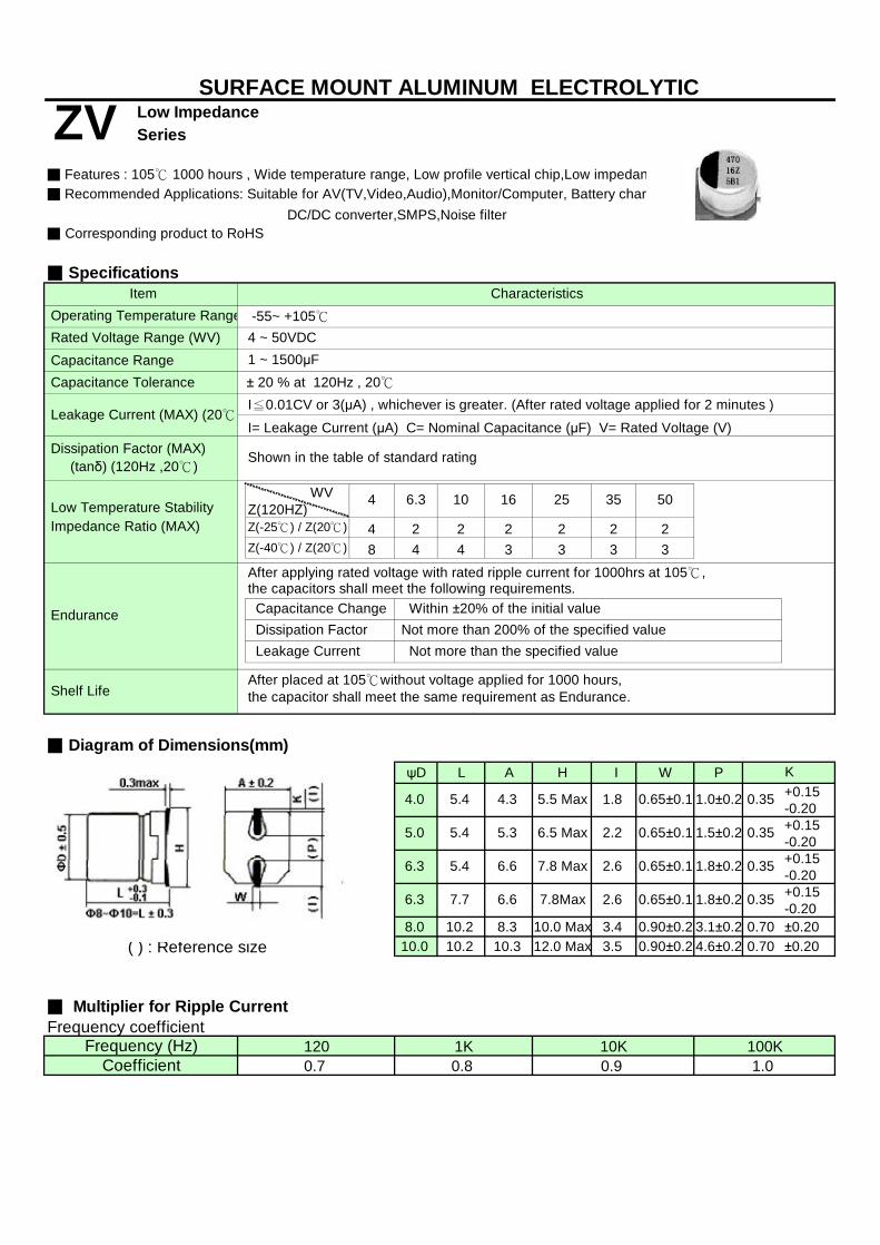
Low Impedance Series
■ Corresponding product to RoHS
■ Specifications
Capacitance Range Capacitance Tolerance
I≦0.01CV or 3(μA) , whichever is greater. (After rated voltage applied for 2 minutes )
I= Leakage Current (μA) C= Nominal Capacitance (μF) V= Rated Voltage (V)
4 2 2 2 2 2 28 4 4 3 3 3 3
■ Diagram of Dimensions(mm)ψD L A H I W P
+0.15-0.20+0.15-0.20+0.15-0.20+0.15-0.20
8.0 10.2 8.3 10.0 Max 3.4 0.90±0.2 3.1±0.2 0.70 ±0.20( ) : Reference size 10.0 10.2 10.3 12.0 Max 3.5 0.90±0.2 4.6±0.2 0.70 ±0.20
■ Multiplier for Ripple CurrentFrequency coefficient
Z(-25℃) / Z(20℃)
Shown in the table of standard rating
Coefficient 0.7
Leakage Current
6.65.4 7.8 Max
0.9
5.0
After placed at 105℃without voltage applied for 1000 hours,the capacitor shall meet the same requirement as Endurance.
Capacitance Change
1.00.8100K
5.5 Max 1.8
0.356.5 Max
-55~ +105℃4 ~ 50VDC
Frequency (Hz) 120 1K 10K
SURFACE MOUNT ALUMINUM ELECTROLYTIC
ZV
1.8±0.20.65±0.1
0.35
0.35
1.8±0.20.65±0.1
K
After applying rated voltage with rated ripple current for 1000hrs at 105℃,
Not more than 200% of the specified value Not more than the specified value
Within ±20% of the initial value
2.66.6
Z(-40℃) / Z(20℃)
7.8Max7.7
6.3
6.3
Dissipation Factor
the capacitors shall meet the following requirements.
2.6
2.2 0.65±0.1 1.5±0.2
± 20 % at 120Hz , 20℃1 ~ 1500μF
6.3
5.4 5.3
Impedance Ratio (MAX) Low Temperature Stability
WVZ(120HZ)
1.0±0.20.65±0.14.0 0.354.35.4
Item Characteristics
DC/DC converter,SMPS,Noise filter
Rated Voltage Range (WV)
Shelf Life
Dissipation Factor (MAX) (tanδ) (120Hz ,20℃)
4
Endurance
5010 16 3525
■ Features : 105℃ 1000 hours , Wide temperature range, Low profile vertical chip,Low impedance■ Recommended Applications: Suitable for AV(TV,Video,Audio),Monitor/Computer, Battery charger,
Leakage Current (MAX) (20℃)
Operating Temperature Range
s

Size tanδ Ripple Z Size tanδ Ripple Z Size tanδ Ripple Z Size tanδ Ripple Z10 4x5.4 0.35 60 4.0 4x5.4 0.22 60 4.0 4x5.4 0.16 60 4.022 4x5.4 0.35 60 4.0 4x5.4 0.26 60 4.0 5x5.4 0.22 95 2.6 5x5.4 0.16 95 2.633 4x5.4 0.35 60 4.0 5x5.4 0.26 95 2.6 5x5.4 0.22 95 2.6 5x5.4 0.16 95 2.647 4x5.4 0.35 60 4.0 5x5.4 0.26 95 2.6 6.3x5.4 0.22 95 1.3 6.3x5.4 0.16 140 1.368 4x5.4 0.35 60 4.0 6.3x5.4 0.26 140 1.3 6.3x5.4 0.22 140 1.3 6.3x7.7 0.20 230 0.8
100 5x5.4 0.35 95 3.0 6.3x5.4 0.26 140 1.3 6.3x5.4 0.22 140 1.3 6.3x7.7 0.20 230 0.8150 6.3x5.4 0.35 140 2.6 6.3x7.7 0.35 230 0.8 6.3x7.7 0.26 230 0.8 8x10.2 0.20 450 0.5220 6.3x5.4 0.35 140 2.6 6.3x7.7 0.35 230 0.8 6.3x7.7 0.26 230 0.8 8x10.2 0.20 450 0.5330 8x10.2 0.35 450 0.5 8x10.2 0.26 450 0.5 10x10.2 0.20 670 0.3470 10x10.2 0.35 670 0.3 10x10.2 0.26 670 0.3 10x10.2 0.20 670 0.31000 10x10.2 0.35 670 0.3 10x10.2 0.26 670 0.31500 10x10.2 0.35 670 0.3
Size tanδ Ripple Z Size tanδ Ripple Z Size tanδ Ripple Z1 4x5.4 0.12 60 4.0 4x5.4 0.12 60 5.0
2.2 4x5.4 0.12 60 4.0 4x5.4 0.12 60 5.03.3 4x5.4 0.12 60 4.0 4x5.4 0.12 60 5.04.7 4x5.4 0.14 60 4.0 4x5.4 0.12 60 4.0 5x5.4 0.12 95 4.06.8 4x5.4 0.14 60 4.0 5x5.4 0.12 95 2.6 6.3x5.4 0.12 140 2.610 5x5.4 0.14 95 2.6 5x5.4 0.12 95 2.6 6.3x5.4 0.12 140 2.622 6.3x5.4 0.14 140 1.3 6.3x5.4 0.12 140 1.3 6.3x7.7 0.12 230 1.333 6.3x5.4 0.14 140 1.3 6.3x7.7 0.14 230 0.8 8x10.2 0.12 300 1.147 6.3x5.4 0.14 140 1.3 6.3x7.7 0.14 230 0.8 10x10.2 0.12 670 0.868 8x10.2 0.16 450 0.5 8x10.2 0.14 450 0.5 10x10.2 0.12 670 0.8
100 8x10.2 0.16 450 0.5 10x10.2 0.14 670 0.3 10x10.2 0.12 670 0.8220 10x10.2 0.16 670 0.3 10x10.2 0.14 670 0.3 10x10.2 0.12 670 0.8330 10x10.2 0.16 670 0.3 10x10.2 0.14 670 0.3470 10x10.2 0.16 670 0.3
☆Size:Dψx L(mm)☆Ripple Current: 105℃,100KHz,(mA/rms)☆Impedance: 20℃,100KHz,Z(Ω).
Capacitance (μF)
ZVCapacitance
(μF)
Rated (Surge) Voltage25(32) 35(44) 50(63)
4(5) 6.3(8) 10(13) 16(20)Rated (Surge) Voltage
■Dimensions,Max Permissible Ripple Current,Max Impedance
Series Low Impedance
SURFACE MOUNT ALUMINUM ELECTROLYTIC
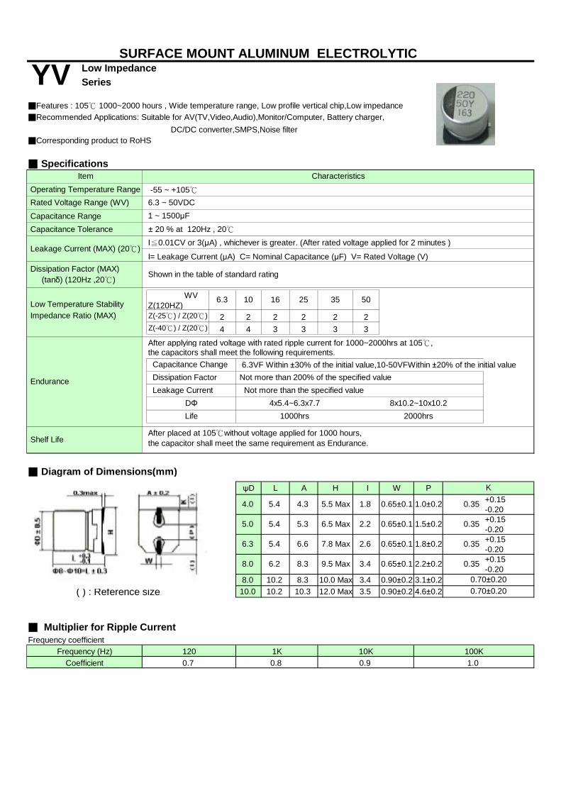
Low Impedance Series
■Corresponding product to RoHS
■ Specifications
Capacitance Range Capacitance Tolerance
I≦0.01CV or 3(μA) , whichever is greater. (After rated voltage applied for 2 minutes )
I= Leakage Current (μA) C= Nominal Capacitance (μF) V= Rated Voltage (V)
2 2 2 2 2 24 4 3 3 3 3
6.3VF Within ±30% of the initial value,10-50VFWithin ±20% of the initial value
■ Diagram of Dimensions(mm)ψD L A H I W P
+0.15-0.20+0.15-0.20+0.15-0.20+0.15-0.20
8.0 10.2 8.3 10.0 Max 3.4 0.90±0.2 3.1±0.2( ) : Reference size 10.0 10.2 10.3 12.0 Max 3.5 0.90±0.2 4.6±0.2
■ Multiplier for Ripple CurrentFrequency coefficient
2000hrs
the capacitors shall meet the following requirements.
Shown in the table of standard rating
Capacitance Change
Characteristics
Dissipation Factor (MAX) (tanδ) (120Hz ,20℃)
Endurance
50
Operating Temperature Range
Dissipation Factor
After applying rated voltage with rated ripple current for 1000~2000hrs at 105℃,
Life
6.65.4 7.8 Max
5.4
0.8
-55 ~ +105℃6.3 ~ 50VDC
0.9
5.0
10K
After placed at 105℃without voltage applied for 1000 hours,the capacitor shall meet the same requirement as Endurance.
1.0
1000hrs
0.7Frequency (Hz) 120 1K 100K
3.4
Coefficient
SURFACE MOUNT ALUMINUM ELECTROLYTIC
YV
0.35
4.0
8x10.2~10x10.2
Item
Z(-40℃) / Z(20℃)
Leakage CurrentDΦ
K
2.26.5 Max
4.3 5.5 Max
5.3
0.35
2.2±0.20.65±0.1
Not more than 200% of the specified value
1.8
Shelf Life
Not more than the specified value
5.4
2.6 0.35
9.5 Max6.2
6.3
8.0 8.3 0.35
0.70±0.20
1.0±0.20.65±0.1
0.65±0.1 1.5±0.2
1.8±0.20.65±0.1
0.70±0.20
4x5.4~6.3x7.7
Impedance Ratio (MAX) Low Temperature Stability
WVZ(120HZ)
Rated Voltage Range (WV)1 ~ 1500μF
± 20 % at 120Hz , 20℃
Z(-25℃) / Z(20℃)
■Features : 105℃ 1000~2000 hours , Wide temperature range, Low profile vertical chip,Low impedance■Recommended Applications: Suitable for AV(TV,Video,Audio),Monitor/Computer, Battery charger,
6.3 10 16 3525
Leakage Current (MAX) (20℃)
DC/DC converter,SMPS,Noise filter
s
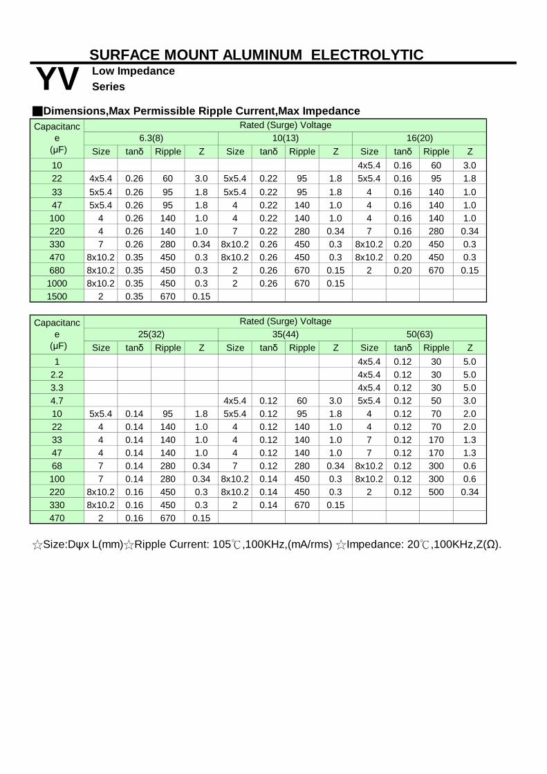
Size tanδ Ripple Z Size tanδ Ripple Z Size tanδ Ripple Z10 4x5.4 0.16 60 3.022 4x5.4 0.26 60 3.0 5x5.4 0.22 95 1.8 5x5.4 0.16 95 1.833 5x5.4 0.26 95 1.8 5x5.4 0.22 95 1.8
6.3x5.4 0.16 140 1.0
47 5x5.4 0.26 95 1.86.3x5.
4 0.22 140 1.06.3x5.
4 0.16 140 1.0100
6.3x5.4 0.26 140 1.0
6.3x5.4 0.22 140 1.0
6.3x5.4 0.16 140 1.0
2206.3x5.
4 0.26 140 1.06.3x7.
7 0.22 280 0.346.3x7.
7 0.16 280 0.34330
6.3x7.7 0.26 280 0.34 8x10.2 0.26 450 0.3 8x10.2 0.20 450 0.3
470 8x10.2 0.35 450 0.3 8x10.2 0.26 450 0.3 8x10.2 0.20 450 0.3680 8x10.2 0.35 450 0.3
10x10.2 0.26 670 0.15
10x10.2 0.20 670 0.15
1000 8x10.2 0.35 450 0.310x10.
2 0.26 670 0.151500
10x10.2 0.35 670 0.15
Size tanδ Ripple Z Size tanδ Ripple Z Size tanδ Ripple Z1 4x5.4 0.12 30 5.0
2.2 4x5.4 0.12 30 5.03.3 4x5.4 0.12 30 5.04.7 4x5.4 0.12 60 3.0 5x5.4 0.12 50 3.010 5x5.4 0.14 95 1.8 5x5.4 0.12 95 1.8
6.3x5.4 0.12 70 2.0
226.3x5.
4 0.14 140 1.06.3x5.
4 0.12 140 1.06.3x5.
4 0.12 70 2.033
6.3x5.4 0.14 140 1.0
6.3x5.4 0.12 140 1.0
6.3x7.7 0.12 170 1.3
476.3x5.
4 0.14 140 1.06.3x5.
4 0.12 140 1.06.3x7.
7 0.12 170 1.368
6.3x7.7 0.14 280 0.34
6.3x7.7 0.12 280 0.34 8x10.2 0.12 300 0.6
1006.3x7.
7 0.14 280 0.34 8x10.2 0.14 450 0.3 8x10.2 0.12 300 0.6220 8x10.2 0.16 450 0.3 8x10.2 0.14 450 0.3
10x10.2 0.12 500 0.34
330 8x10.2 0.16 450 0.310x10.
2 0.14 670 0.15470
10x10.2 0.16 670 0.15
☆Size:Dψx L(mm)☆Ripple Current: 105℃,100KHz,(mA/rms) ☆Impedance: 20℃,100KHz,Z(Ω).
Capacitance
(μF)
YVCapacitanc
e (μF)
Rated (Surge) Voltage25(32) 35(44) 50(63)
6.3(8) 10(13) 16(20)
SURFACE MOUNT ALUMINUM ELECTROLYTIC
Rated (Surge) Voltage■Dimensions,Max Permissible Ripple Current,Max Impedance
Series Low Impedance

Series
■Corresponding product to RoHS
■ Specifications
Capacitance Range Capacitance Tolerance
I≦0.01CV or 3μA whichever is greater(After rated voltage applied for 2 minutes)
I= Leakage Current (μA) C= Nominal Capacitance (μF) V= Rated Voltage (V)
2 2 2 2 2 23 3 3 3 3 3
■ Diagram of Dimensions(mm)
ψD L A H I W P+0.15-0.20+0.15-0.20+0.15-0.20+0.15-0.20
■ Multiplier for Ripple CurrentFrequency coefficient
1.000.80
10K
12.0 Max 3.5 0.90±0.2
100K
0.90
3.1±0.210.2
10.2 10.3 4.6±0.2
10.0 Max 3.4 0.90±0.2
7.7 0.65±0.17.8 Max6.6
Shown in the table of standard rating
WVZ(120HZ)
50
± 20 % at 120Hz , 20℃
Coefficient 0.70
-55 ~ +105℃6.3 ~ 50VDC
the capacitor shall meet the following requirement.
0.35
0.70
1.8±0.2
0.35
1.8
1.8±0.2
Operating Temperature Range
Dissipation Factor (MAX) (tanδ) (120Hz ,20℃)
Within±30% of the initial value
Leakage Current (MAX) (20℃)
4.7 ~ 1500μF Rated Voltage Range (WV)
Not more than 200% of the specified value Not more than the specified value
SURFACE MOUNT ALUMINUM ELECTROLYTIC
EV Ultra Low Impedance
Endurance
0.35
Frequency (Hz) 120 1K
0.65±0.1
8.0
10.0
8.3
2.6
5.5 Max
6.3
5.0 2.26.5 Max
6.65.46.3 2.67.8 Max
K
5.4 5.3 1.5±0.2 0.35
1.0±0.20.65±0.1
0.65±0.1
4.35.4
Shelf Life
Z(-40℃) / Z(20℃)
Dissipation Factor
After applying rated voltage with rated ripple current for 2000 hours at 105℃,
After placed at 105℃without voltage applied for 1000 hours,the capacitor shall meet the same requirement as Endurance.
Leakage Current
Capacitance Change
4.0
OA/HA/Communication ,SMPS
Low Temperature Stability
Item Characteristics
Z(-25℃) / Z(20℃) Impedance Ratio (MAX)
±0.2
0.70 ±0.2
■Features : 105℃ 2000 hours , Low profile vertical chip, Ultra low impedance■Recommended Applications: AV(TV,Video,Audio) ,Monitor/Computer,
6.3 10 16 3525
s
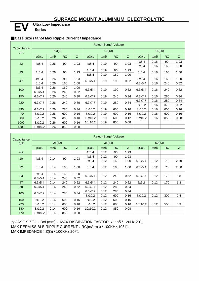
ψDxL tanδ RC Z ψDxL tanδ RC Z ψDxL tanδ RC Z4x5.4 0.16 90 1.935x5.4 0.16 160 1.00
4x5.4 0.19 90 1.935x5.4 0.19 160 1.00
4x5.4 0.26 90 1.93 5x5.4 0.16 160 1.005x5.4 0.26 160 1.00 6.3x5.4 0.16 240 0.525x5.4 0.26 160 1.00
6.3x5.4 0.26 240 0.52150 6.3x7.7 0.26 240 0.30 6.3x7.7 0.19 240 0.34 6.3x7.7 0.16 280 0.34
6.3x7.7 0.16 280 0.348x10.2 0.16 370 0.22
330 6.3x7.7 0.26 280 0.34 8x10.2 0.19 600 0.16 8x10.2 0.16 600 0.16470 8x10.2 0.26 600 0.16 8x10.2 0.19 600 0.16 8x10.2 0.16 600 0.16680 8x10.2 0.26 600 0.16 10x10.2 0.19 600 0.12 10x10.2 0.16 850 0.08
1000 8x10.2 0.26 600 0.16 10x10.2 0.19 850 0.081500 10x10.2 0.26 850 0.08
ψDxL tanδ RC Z ψDxL tanδ RC Z ψDxL tanδ RC Z4.7 4x5.4 0.12 90 1.93
4x5.4 0.12 90 1.935x5.4 0.12 160 1.00 6.3x5.4 0.12 70 2.60
5x5.4 0.14 160 1.006.3x5.4 0.14 240 0.52
47 6.3x5.4 0.14 240 0.52 6.3x5.4 0.12 240 0.52 8x6.2 0.12 170 1.368 6.3x5.4 0.14 240 0.52 6.3x7.7 0.12 280 0.34
6.3x7.7 0.12 280 0.348x10.2 0.12 600 0.16 8x10.2 0.12 300 0.4
150 8x10.2 0.14 600 0.16 8x10.2 0.12 600 0.16220 8x10.2 0.14 600 0.16 8x10.2 0.12 600 0.16 10x10.2 0.12 500 0.3330 8x10.2 0.14 600 0.16 10x10.2 0.12 850 0.08470 10x10.2 0.14 850 0.08
10(13)
0.52
0.52
1.93
6.3x5.4 0.19 190
0.19
190
90
160
16(20)
Rated (Surge) Voltage
100
1.00
33 6.3x5.4
25(32) 35(44)
6.3(8)
0.16 240
22 5x5.4 0.14 160
10 4x5.4 0.14 90
4x5.4 0.26 90
1.93
0.52
220 6.3x7.7 0.26 240 0.30
90 5x5.4 0.16 1601.93
100
47 6.3x5.4 0.19
6.3x5.4
☆CASE SIZE:ψDxL(mm)、 MAX DISSIPATION FACTOR :tanδ / 120Hz,20℃.MAX PERMISSIBLE RIPPLE CURRENT:RC(mArms) / 100KHz,105℃.MAX IMPEDANCE:Z(Ω) / 100KHz,20℃.
EVCapacitance
(μF)
Capacitance (μF)
4x5.41.93
33 4x5.4 0.26
22
SURFACE MOUNT ALUMINUM ELECTROLYTIC
■Case Size / tanδ/ Max Ripple Current / Impedance
SeriesUltra Low Impedance
6.3x7.7 0.19 280 0.34
1.00
Rated (Surge) Voltage
6.3x7.7 0.12 170 0.8
50(63)
0.12 240 0.52
1.00 6.3x5.4 0.12 70 2.00
6.3x7.7 0.14 280 0.34
5x5.4 0.12

Series
■Corresponding product to RoHS
■ Specifications
Capacitance Range Capacitance Tolerance
I≦0.01CV or 3μA whichever is greater(After rated voltage applied for 2 minutes)
I= Leakage Current (μA) C= Nominal Capacitance (μF) V= Rated Voltage (V)
2 2 2 2 23 3 3 3 3
■ Diagram of Dimensions(mm)
ψD L A H I W P+0.15-0.20+0.15-0.20+0.15-0.20+0.15-0.20
■ Multiplier for Ripple CurrentFrequency coefficient
10.2
10.2 10.3 4.6±0.2
1.000.80
10K
12.0 Max 3.5 0.90±0.210.0
100K
1.8±0.27.7 0.65±0.17.8 Max
0.70±0.2
0.70±0.2
10.0 Max 3.4 0.90±0.2 3.1±0.2
Shown in the table of standard rating
WVZ(120HZ)
10~ 1800μF± 20 % at 120Hz , 20℃
Item
Capacitance Change
Characteristics
Dissipation Factor (MAX) (tanδ) (120Hz ,20℃)
Within±30% of the initial value
Leakage Current (MAX) (20℃)
Rated Voltage Range (WV)
Z(-25℃) / Z(20℃)
Operating Temperature Range
Coefficient 0.70
-55 ~ +105℃6.3 ~ 35VDC
the capacitor shall meet the following requirement.
0.35
0.90
8.0
0.35
1.8
1.8±0.2
0.65±0.1 1.5±0.2 0.35
0.354.3
Not more than 200% of the specified value Not more than the specified value
5.4 5.5 Max
2.66.3 6.6
( ) : Reference size
SURFACE MOUNT ALUMINUM ELECTROLYTIC
JV Ultra Low Impedance
Leakage Current
After placed at 105℃without voltage applied for 1000 hours,the capacitor shall meet the same requirement as Endurance.
4.0
K
Frequency (Hz) 120 1K
0.65±0.1
8.3
5.0 2.26.5 Max
6.65.46.3 2.67.8 Max
5.4 5.3
Low Temperature Stability
1.0±0.20.65±0.1
Impedance Ratio (MAX)
Endurance
Shelf Life
Z(-40℃) / Z(20℃)
Dissipation Factor
After applying rated voltage with rated ripple current for 2000 hours at 105℃,
■Features : 105℃ 2000 hours , Low profile vertical chip, Ultra low impedance■Recommended Applications: AV(TV,Video,Audio) ,Monitor/Computer,
6.3 10 16 3525
OA/HA/Communication ,SMPS
s
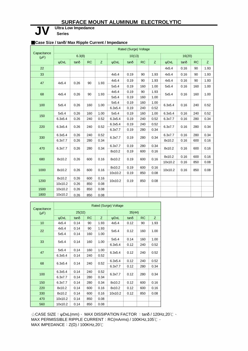
ψDxL tanδ RC Z ψDxL tanδ RC Z ψDxL tanδ RC Z
22 4x5.4 0.16 90 1.93
33 4x5.4 0.19 90 1.93 4x5.4 0.16 90 1.93
4x5.4 0.19 90 1.93 4x5.4 0.16 90 1.93
5x5.4 0.19 160 1.00 5x5.4 0.16 160 1.004x5.4 0.19 90 1.935x5.4 0.19 160 1.005x5.4 0.19 160 1.00
6.3x5.4 0.19 240 0.525x5.4 0.26 160 1.00 5x5.4 0.19 160 1.00 6.3x5.4 0.16 240 0.52
6.3x5.4 0.26 240 0.52 6.3x5.4 0.19 240 0.52 6.3x7.7 0.16 280 0.346.3x5.4 0.19 240 0.526.3x7.7 0.19 280 0.34
6.3x5.4 0.26 240 0.52 6.3x7.7 0.16 280 0.346.3x7.7 0.26 280 0.34 8x10.2 0.16 600 0.16
6.3x7.7 0.19 280 0.348x10.2 0.19 600 0.16
8x10.2 0.16 600 0.1610x10.2 0.16 850 0.08
8x10.2 0.19 600 0.1610x10.2 0.19 850 0.08
8x10.2 0.26 600 0.1610x10.2 0.26 850 0.08
1500 10x10.2 0.26 850 0.081800 10x10.2 0.26 850 0.08
ψDxL tanδ RC Z ψDxL tanδ RC Z10 4x5.4 0.14 90 1.93 4x5.4 0.12 90 1.93
4x5.4 0.14 90 1.935x5.4 0.14 160 1.00
5x5.4 0.14 160 1.006.3x5.4 0.12 240 0.52
5x5.4 0.14 160 1.006.3x5.4 0.14 240 0.52
6.3x5.4 0.12 240 0.526.3x7.7 0.12 280 0.34
6.3x5.4 0.14 240 0.526.3x7.7 0.14 280 0.34
150 6.3x7.7 0.14 280 0.34 8x10.2 0.12 600 0.16220 8x10.2 0.14 600 0.16 8x10.2 0.12 600 0.16330 8x10.2 0.14 600 0.16 10x10.2 0.12 850 0.08470 10x10.2 0.14 850 0.08560 10x10.2 0.14 850 0.08
600 0.16
160 1.00
6.3x5.4 0.26 240 0.52
5x5.4 0.26
16(20)
25(32) 35(44)
Rated (Surge) Voltage
6.3(8) 10(13)
0.26 90 1.93
☆CASE SIZE:ψDxL(mm)、 MAX DISSIPATION FACTOR :tanδ / 120Hz,20℃、MAX PERMISSIBLE RIPPLE CURRENT:RC(mArms) / 100KHz,105℃、MAX IMPEDANCE:Z(Ω) / 100KHz,20℃
JVCapacitance
(μF)
Capacitance (μF)
240 0.52
SURFACE MOUNT ALUMINUM ELECTROLYTIC
■Case Size / tanδ/ Max Ripple Current / Impedance
SeriesUltra Low Impedance
Rated (Surge) Voltage
1200
47 4x5.4
68
6.3x7.7
8x10.2
8x10.2 0.26
6.3x5.4
22
47
5x5.4 0.12
0.12
5x5.4 0.14 160
100
330
100
680
220
470
1000
33
68
150
0.16 160 1.004x5.4 0.26 90 1.93 5x5.4
6.3x7.7 0.16 280 0.34
6.3x5.4 0.16 240 0.52
0.26 280 0.34 8x10.2
6.3x7.7 0.19 280 0.34
0.16 600 0.16
8x10.2 0.19 600 0.16
0.08
10x10.2 0.19 850 0.08
0.26 600 0.16 10x10.2 850
160 1.00
6.3x7.7 0.12 280 0.34
6.3x5.4 0.14 240 0.52
1.00
0.16
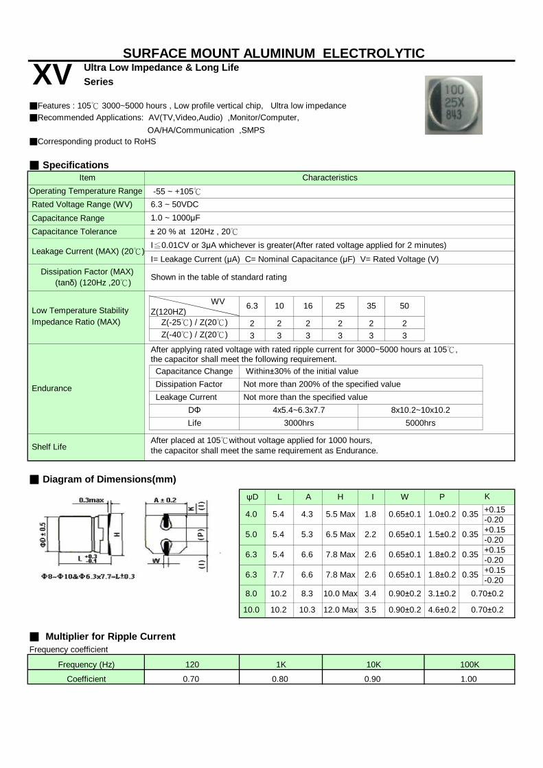
Series
■Corresponding product to RoHS
■ Specifications
Capacitance Range Capacitance Tolerance
I≦0.01CV or 3μA whichever is greater(After rated voltage applied for 2 minutes)
I= Leakage Current (μA) C= Nominal Capacitance (μF) V= Rated Voltage (V)
2 2 2 2 2 23 3 3 3 3 3
■ Diagram of Dimensions(mm)
ψD L A H I W P+0.15-0.20+0.15-0.20+0.15-0.20+0.15-0.20
■ Multiplier for Ripple CurrentFrequency coefficient
OA/HA/Communication ,SMPS
Operating Temperature Range
Impedance Ratio (MAX)
Endurance
Shelf Life
DΦ 4x5.4~6.3x7.7
Z(-40℃) / Z(20℃)
■Features : 105℃ 3000~5000 hours , Low profile vertical chip, Ultra low impedance■Recommended Applications: AV(TV,Video,Audio) ,Monitor/Computer,
6.3 10 16 Low Temperature Stability
Item Characteristics
Dissipation Factor
5.0
After placed at 105℃without voltage applied for 1000 hours,the capacitor shall meet the same requirement as Endurance.
8x10.2~10x10.2
4.0 1.0±0.2
Not more than the specified value
Life 3000hrs 5000hrs
Leakage Current
2.2
0.65±0.1
Frequency (Hz) 120 1K
6.5 Max
4.3
10.2
1.5±0.2
2.6
100K
SURFACE MOUNT ALUMINUM ELECTROLYTIC
XV Ultra Low Impedance & Long Life
0.35
K
After applying rated voltage with rated ripple current for 3000~5000 hours at 105℃,
Not more than 200% of the specified value
7.8 Max
5.4 5.5 Max
0.35
1.8
1.8±0.20.65±0.1
0.65±0.1
Leakage Current (MAX) (20℃)
Rated Voltage Range (WV)
Z(-25℃) / Z(20℃)
Capacitance Change
Dissipation Factor (MAX) (tanδ) (120Hz ,20℃)
Within±30% of the initial value
Coefficient 0.70
6.3 ~ 50VDC
the capacitor shall meet the following requirement.
0.35
0.90
0.90±0.2
6.6
10.3
Shown in the table of standard rating
WVZ(120HZ)
50
1.0 ~ 1000μF± 20 % at 120Hz , 20℃
-55 ~ +105℃
3525
0.35
8.0
10.0
5.4 5.3
6.3
6.65.46.3
8.3
1.000.80
1.8±0.2
4.6±0.2
7.7
10K
2.6 0.65±0.17.8 Max
12.0 Max10.2 3.5
0.70±0.2
0.70±0.2
10.0 Max 3.4 0.90±0.2 3.1±0.2
s

ψDxL tanδ RC Z ψDxL tanδ RC Z ψDxL tanδ RC Z
10 4x5.4 0.16 90 1.9322 4x5.4 0.26 90 1.93 4x5.4 0.19 90 1.93 5x5.4 0.16 160 1.0033 4x5.4 0.26 90 1.93 5x5.4 0.19 160 1.00 6.3x5.4 0.16 240 0.5247 5x5.4 0.26 160 1.00 6.3x5.4 0.19 190 0.52 6.3x5.4 0.16 240 0.52100 6.3x5.4 0.26 240 0.52 6.3x5.4 0.19 190 0.52 6.3x7.7 0.16 280 0.34150 6.3x7.7 0.26 240 0.30 6.3x7.7 0.19 240 0.34 8x10.2 0.16 370 0.22220 6.3x7.7 0.26 240 0.30 8x10.2 0.19 600 0.16 8x10.2 0.16 370 0.22
330 8x10.2 0.26 600 0.16 8x10.2 0.19 600 0.16 8x10.2 0.16 600 0.16
470 8x10.2 0.26 600 0.16 10x10.2 0.19 850 0.12 10x10.2 0.16 850 0.12680 10x10.2 0.26 850 0.12 10x10.2 0.19 850 0.12 10x10.2 0.16 850 0.12
1000 10x10.2 0.26 850 0.12 10x10.2 0.19 850 0.12
ψDxL tanδ RC Z ψDxL tanδ RC Z ψDxL tanδ RC Z1 4x5.4 0.12 60 5.00
2.2 4x5.4 0.12 60 5.003.3 4x5.4 0.12 60 5.004.7 4x5.4 0.12 90 1.93 5x5.4 0.12 95 4.0010 4x5.4 0.14 90 1.93 5x5.4 0.12 160 1.00 6.3x5.4 0.12 140 2.6022 5x5.4 0.14 160 1.00 5x5.4 0.12 160 1.00 6.3x7.7 0.12 230 1.3033 6.3x5.4 0.14 240 0.52 6.3x5.4 0.12 240 0.52 8x10.2 0.12 350 0.5047 6.3x5.4 0.14 240 0.52 6.3x7.7 0.12 280 0.34 10x10.2 0.12 670 0.3468 6.3x7.7 0.14 280 0.34 6.3x7.7 0.12 280 0.34 10x10.2 0.12 670 0.34100 6.3x7.7 0.14 300 0.34 8x10.2 0.12 600 0.16 10x10.2 0.12 670 0.34150 8x10.2 0.14 600 0.16 10x10.2 0.12 850 0.12 10x10.2 0.12 670 0.34220 8x10.2 0.14 600 0.16 10x10.2 0.12 850 0.12 10x10.2 0.12 670 0.34330 10x10.2 0.14 850 0.12 10x10.2 0.12 850 0.12470 10x10.2 0.14 850 0.12
6.3(8) 10(13)
SURFACE MOUNT ALUMINUM ELECTROLYTIC
■Case Size / tanδ/ Max Ripple Current / Impedance
Series Ultra Low Impedance & Long Life
50(63)
Rated (Surge) Voltage
☆CASE SIZE:ψDxL(mm)、 MAX DISSIPATION FACTOR :tanδ / 120Hz,20℃、MAX PERMISSIBLE RIPPLE CURRENT:RC(mArms) / 100KHz,105℃、MAX IMPEDANCE:Z(Ω) / 100KHz,20℃
XVCapacitance
(μF)
Capacitance (μF)
16(20)
Rated (Surge) Voltage
25(32) 35(44)

Series
■ Specifications
Capacitance Range Capacitance Tolerance
I≦0.01CV or 3μA whichever is greater(After rated voltage applied for 2 minutes)
I= Leakage Current (μA) C= Nominal Capacitance (μF) V= Rated Voltage (V)
2 2 2 2 23 3 3 3 3
■ Diagram of Dimensions(mm)
ψD L A H I W P+0.15-0.20
■ Multiplier for Ripple CurrentFrequency coefficient
4.6±0.2
10.0 Max
0.70±0.210.0
8.310.28.0
10.2 10.3 12.0 Max 3.5 0.90±0.2
Characteristics
Dissipation Factor (MAX) (tanδ) (120Hz ,20℃)
Within±30% of the initial value
Leakage Current (MAX) (20℃)
Rated Voltage Range (WV)
Z(-25℃) / Z(20℃)
47 ~ 1000μF
After applying rated voltage for 1000~2000 hours at 125℃,
0.70±0.2
Capacitance Change
3.1±0.2
2.2±0.2
3.4
9.5 Max
0.90±0.2
120 1K
Coefficient 0.70 0.90
10K
SURFACE MOUNT ALUMINUM ELECTROLYTIC
HV Ultra Low Impedance & High temperature
1.000.80
100K
( ) : Reference size
Frequency (Hz)
Endurance
Shelf Life
3.4
the capacitor shall meet the following requirement.
6.2 8.3
6.3x7.7-8x6.2Life
Shown in the table of standard rating
WVZ(120HZ)
DΦ
0.65±0.1
Low Temperature Stability
Z(-40℃) / Z(20℃)
-40 ~ +125℃10 ~ 50VDC
35
Item
Impedance Ratio (MAX)
± 20 % at 120Hz , 20℃
Operating Temperature Range
Dissipation Factor
8.0
After placed at 125℃without voltage applied for 1000 hours(500 hours for 8x6.2),the capacitor shall meet the same requirement as Endurance.
K
Not more than 300% of the specified value
0.35
≧8x10.2
Not more than the specified value Leakage Current1000hrs 2000hrs
■Features : 125℃1000~ 2000 hours ,Higher temperature range■Recommended Applications: Automatic Mounting and Reflow Soldering
10 16 25 50
■Corresponding product to RoHS
s

ψDxL tanδ RC ψDxL tanδ RC ψDxL tanδ RC
6.3x7.7 0.18 70
8x6.2 0.18 75
6.3x7.7 0.18 70
8x6.2 0.18 75
8x6.2 0.20 75 8x10.2 0.18 130
6.3x7.7 0.26 70
8x6.2 0.26 75220 8x10.2 0.26 130 8x10.2 0.20 130 10x10.2 0.18 180330 8x10.2 0.26 130 8x10.2 0.20 180 10x10.2 0.18 180
470 10x10.2 0.26 180 10x10.2 0.20 180680 10x10.2 0.26 180
1000 10x10.2 0.26 180
ψDxL tanδ RC ψDxL tanδ RC22 6.3x7.7 0.14 70 8x6.2 0.12 75
6.3x7.7 0.14 708x6.2 0.14 758x6.2 0.14 75
8x10.2 0.14 130100 8x10.2 0.14 130 10x10.2 0.12 180
150 10x10.2 0.14 180220 10x10.2 0.14 180330
8x10.2
8x6.2 0.26 75
☆CASE SIZE:ψDxL(mm)、 MAX DISSIPATION FACTOR :tanδ / 120Hz,20℃、MAX PERMISSIBLE RIPPLE CURRENT:RC(mArms) / 120Hz,125℃、
Capacitance (μF) 35(44)
150
SURFACE MOUNT ALUMINUM ELECTROLYTIC
■Case Size / tanδ/ Max Ripple Current
SeriesHigh temperatureHV
Capacitance (μF) 25(32)
Rated (Surge) Voltage
10(13) 16(20)
8x10.2 0.18 130
Rated (Surge) Voltage
0.20 70
6.3x7.7 0.20 70
0.20 130
47
33 8x10.2
6.3x7.7100
50(63)
0.12 130
47 8x10.2 0.12 130
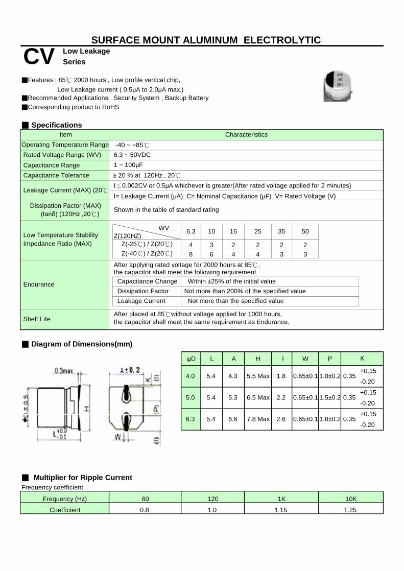
Series
■Corresponding product to RoHS
■ Specifications
Capacitance Range Capacitance Tolerance
I≦0.002CV or 0.5μA whichever is greater(After rated voltage applied for 2 minutes)
I= Leakage Current (μA) C= Nominal Capacitance (μF) V= Rated Voltage (V)
4 3 2 2 2 28 6 4 4 3 3
■ Diagram of Dimensions(mm)
ψD L A H I W P
+0.15
-0.20
+0.15
-0.20
+0.15
-0.20
■ Multiplier for Ripple CurrentFrequency coefficient
Leakage Current (MAX) (20℃)
Rated Voltage Range (WV)
Low Temperature Stability
0.35
0.35
■Features : 85℃ 2000 hours , Low profile vertical chip, Low Leakage current ( 0.5μA to 2.0μA max.)
6.3 10 16 35
Shelf Life
2.26.5 Max
6.6
1.0±0.20.65±0.1
0.65±0.1 1.5±0.2
1.8±0.26.3
Dissipation Factor
5.0
After placed at 85℃without voltage applied for 1000 hours,the capacitor shall meet the same requirement as Endurance.
2.6
4.0
0.35
4.35.4 5.5 Max
5.4
1.8
0.65±0.1
Dissipation Factor (MAX) (tanδ) (120Hz ,20℃)
-40 ~ +85℃6.3 ~ 50VDC
K
After applying rated voltage for 2000 hours at 85℃,
Not more than 200% of the specified value Not more than the specified value
Impedance Ratio (MAX)
Endurance
1K
1.251.0
SURFACE MOUNT ALUMINUM ELECTROLYTIC
CV Low Leakage
Capacitance Change
Characteristics
Coefficient 0.8
Frequency (Hz) 60 120
the capacitor shall meet the following requirement.
10K
Leakage Current
Shown in the table of standard rating
1.15
Within ±25% of the initial value
7.8 Max
5.4 5.3
50
■Recommended Applications: Security System , Backup Battery
WVZ(120HZ)
Z(-25℃) / Z(20℃)Z(-40℃) / Z(20℃)
Item
1 ~ 100μF± 20 % at 120Hz , 20℃
25
Operating Temperature Range
s

ψDxL tanδ RC ψDxL tanδ RC ψDxL tanδ RC
10 4x5.4 0.16 28
22 4x5.4 0.26 20 4x5.4 0.30 28 5x5.4 0.16 39
33 5x5.4 0.26 22 5x5.4 0.20 43 6.3x5.4 0.16 66
47 5x5.4 0.26 46 5x5.4 0.30 43 6.3x5.4 0.16 70
100 6.3x5.4 0.26 71 6.3x5.4 0.26 70
ψDxL tanδ RC ψDxL tanδ RC ψDxL tanδ RC
1 4x5.4 0.12 10
2.2 4x5.4 0.12 16
3.3 4x5.4 0.12 16
4.7 4x5.4 0.14 22 4x5.4 0.12 22 5x5.4 0.12 23
10 5x5.4 0.14 28 5x5.4 0.12 30 6.3x5.4 0.12 35
22 6.3x5.4 0.14 55 6.3x5.4 0.12 60
33 6.3x5.4 0.14 65
Rated (Surge) Voltage
■Case Size / tanδ/ Max Ripple Current / ESR
SeriesCV Low LeakageSURFACE MOUNT ALUMINUM ELECTROLYTIC
☆CASE SIZE:ψDxL(mm)、 MAX DISSIPATION FACTOR :tanδ /120Hz,20℃、 MAX PERMISSIBLERIPPLE CURRENT:RC(mArms) / 120Hz,85℃、
Capacitance (μF)
Capacitance (μF)
Rated (Surge) Voltage
25(32) 35(44) 50(63)
6.3(8) 10(13) 16(20)
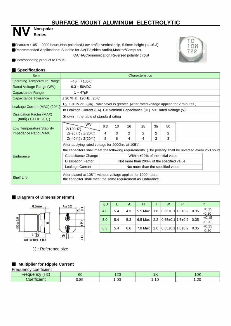
Non-polar Series
■Corresponding product to RoHS
■ Specifications
Capacitance Range Capacitance Tolerance
I≦0.01CV or 3(μA) , whichever is greater. (After rated voltage applied for 2 minutes )
I= Leakage Current (μA) C= Nominal Capacitance (μF) V= Rated Voltage (V)
4 3 2 2 2 28 6 4 4 3 3
■ Diagram of Dimensions(mm)ψD L A H I W P
+0.15-0.20+0.15-0.20+0.15-0.20
( ) : Reference size
■ Multiplier for Ripple CurrentFrequency coefficient
■Features :105℃ 2000 hours,Non-polarized,Low profile vertical chip, 5.5mm height (≦ψ6.3)
WV Z(120HZ)
Z(-25℃) / Z(20℃)Z(-40℃) / Z(20℃)
Impedance Ratio (MAX) Low Temperature Stability
■Recommended Applications: Suitable for AV(TV,Video,Audio),Monitor/Computer, OA/HA/Communication,Reversed polarity circuit
1 ~ 47μF
Dissipation Factor (MAX) (tanδ) (120Hz ,20℃)
Item Characteristics
Rated Voltage Range (WV)
± 20 % at 120Hz , 20℃
Shown in the table of standard rating
After placed at 105℃ without voltage applied for 1000 hours,the capacitor shall meet the same requirement as Endurance.
Within ±20% of the initial value Not more than 200% of the specified value
Not more than the specified value Dissipation Factor Leakage Current
1.0±0.2
1.5±0.2
1.8±0.2
0.35
0.35
K
6.5 Max
1.84.3 5.5 Max
7.8 Max
5.3 2.2
0.65±0.1
SURFACE MOUNT ALUMINUM ELECTROLYTIC
NV
Shelf Life
4.0
5.0
6.3 2.6
5.4
Frequency (Hz) 60 120 1K
5.4
5.4
Coefficient 0.85
-40 ~ +105℃6.3 ~ 50VDC
1.00 1.10
506.3
Operating Temperature Range
Capacitance Change
After applying rated voltage for 2000hrs at 105℃,
Endurance
10 16 3525
the capacitors shall meet the following requirements. (The polarity shall be reversed every 250 hours)
Leakage Current (MAX) (20℃)
1.20
6.6
10K
0.65±0.1
0.65±0.1 0.35
s
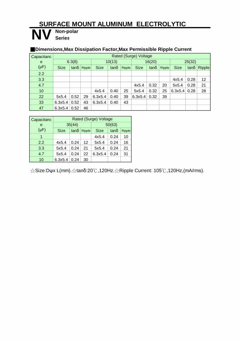
Non-polar Series
Size tanδ Ripple Size tanδ Ripple Size tanδ Ripple Size tanδ Ripple2.23.3 4x5.4 0.28 124.7 4x5.4 0.32 20 5x5.4 0.28 2110 4x5.4 0.40 25 5x5.4 0.32 25 6.3x5.4 0.28 2822 5x5.4 0.52 29 6.3x5.4 0.40 39 6.3x5.4 0.32 3933 6.3x5.4 0.52 43 6.3x5.4 0.40 4347 6.3x5.4 0.52 46
Size tanδ Ripple Size tanδ Ripple
1 4x5.4 0.24 102.2 4x5.4 0.24 12 5x5.4 0.24 163.3 5x5.4 0.24 21 5x5.4 0.24 214.7 5x5.4 0.24 22 6.3x5.4 0.24 3110 6.3x5.4 0.24 30
☆Size:Dψx L(mm).☆tanδ:20℃,120Hz.☆Ripple Current: 105℃,120Hz,(mA/rms).
6.3(8)
Capacitance
(μF)35(44) 50(63)
Rated (Surge) Voltage
SURFACE MOUNT ALUMINUM ELECTROLYTIC
Rated (Surge) Voltage10(13) 16(20)
NVCapacitanc
e (μF)
■Dimensions,Max Dissipation Factor,Max Permissible Ripple Current
25(32)

General purposeSeries
■ Features: 85℃ 2000 hours■ Recommended Applications: For general purpose , decoupling , by pass and filtering circuit in entertainment electronics■ Corresponding product to RoHS
■ Specifications
Rated Capacitance Range Capacitance Tolerance
(After rated voltage applied for 2 minutes )
6.3 10 16 25 35 50 63 100 160~250 350~5000.24 0.20 0.16 0.14 0.12 0.10 0.10 0.10 0.20 0.24
8 6 5 3 3 7 10 1510 8 6 4 3 — — —
the capacitors shall meet the following requirements.
After placed at 85℃ without voltage applied for 1000 hours,the capacitors shall meet the same requirement as Endurance.
■ Diagram of Dimensions
6.3 8 10 13 16 182.5 3.50.5 0.61.5 1.5 1.5 2.0 2.0 2.0
■ Multiplier for Ripple CurrentFrequency coefficient
1.13160 ~ 450V 220μF Above 1.00 1.10 1.13
a 1.5
1.40
1.00 1.05 1.10 1.10
1.201.00 1.05 1.15
10K1.00 1.20 1.30 1.50120 300 1K
1.10 1.15
1.25 1.401.10
Pψd 0.8
2.0 7.50.5
ALUMINUM ELECTROLYTIC CAPACITORS
160 ~ 450V Below 220μF
500V
Frequency (Hz)
Impedance Ratio (MAX)
6.3 ~ 100VDC1 ~ 22000μF
I=0.01CV or 3μA
Rated Voltage Range
Leakage Current (MAX) (20℃)
2.0
Shelf Life
6.3 ~ 100V Below 68μF6.3 ~ 100V 100 ~ 680μF
6.3 ~ 100V 1000 ~ 22000μF1.00
1.00
5ψD
± 20 % at 120Hz , 20℃
Capacitance Change
35~100
WV
When nominal capacitance is over 1000uF,tanδ shall be added 0.02 to the listed value with increase of every 1000uF。
SK
Operating Temperature Range Item Characteristics
-40~+85℃ -25~+85℃160 ~ 500VDC
After applying rated voltage for 2000 hours at 85℃
1 ~ 470μF
25
whichever is greater. I=0.03CV+10(μA)
10 16 160~250 315~350
Dissipation Factor (MAX) (tanδ) (120Hz ,20℃)
Endurance
Leakage Current
Z-25℃ / Z+20℃Z-40℃ / Z+20℃
Low Temperature Stability
Not more than 200% of the specified value initial specified value or less
tanδ
10.00.8
Dissipation Factor
400~500
Within ± 20 % of initial value
WV Z(120Hz) 6.3
22
5.00.6

General purposeSeries
Size Ripple Size Ripple Size Ripple Size Ripple Size Ripple Size Ripple Size Ripple1.0 5x11 10 5x11 102.2 5x11 23 5x11 293.3 5x11 35 5x11 404.7 5x11 20 5x11 25 5x11 30 5x11 35 5x11 40 5x11 456.8 5x11 5010 5x11 35 5x11 40 5x11 50 5x11 60 5x11 65 5x11 70
5X11 35 5x11 55 5x11 75 5x11 90 5x11 95 5x11 100 5x11 956.3x11 115
33 5X11 55 5x11 80 5x11 110 5x11 115 5x11 120 5x11 105 6.3x11 13047 5x11 75 5x11 95 5x11 130 5x11 135 5x11 120 6.3x11 140 6.3x11 19068 5x11 150 5x11 145
100 5x11 130 5x11 180 5x11 165 6.3x11 160 6.3x11 185 8x11 230 10x12.5 300150 6.3x11 205
5x11 200 6.3x11 250 6.3x11 260 8x11 290 8x11 290 10x12.5 380 10x15 4106.3x11 240 10x20 4906.3x11 260 6.3x11 265 6.3x11 290 8x11 315 10x12.5 420 10x15 490 10x20 540
8x11 3606.3x11 330 6.3x11 320 8x11 400 8x15 420 10x15 430 10x20 610 13x20 755
10x12.5 460680 8x11 410 8x11 410 10x12.5 510 10x15 550 10x20 550 13x25 965
8x11 460 10x12.5 580 10x15 630 10x20 760 13x20 950 13x25 1100 16x25 131010x12.5 580 13x16 76010x20 840 10x20 880 13x20 1100 13x25 1300 16x25 1600 16x36 1850 18x36 2200
18x32 185010x20 1000 13x20 1250 13x25 1400 16x25 1660 16x36 1970 18x36 2170 22x40 2500
18x32 20504700 13x20 1300 13x25 1500 16x25 1800 16x32 1950 18x36 2400 22X40 25006800 13x25 1550 16x25 1900 16x32 1980 18x36 2550 22x40 2600
16x25 1900 16x36 2225 18x36 2700 22x40 280018x32 2225
16x36 2500 18x36 2950 22x40 3150 22x40 3200
22000 18x40 3650 22x40 3700 22x40 3800
35 (44) 50 (63)
☆ Size: Dψx L (mm) ☆ Ripple Current: (mA/rms). 85℃,120Hz
220
470
330
15000
Rated (Surge) Voltage
6.3 (8) 10 (13) 16 (20) 25 (32)
ALUMINUM ELECTROLYTIC CAPACITORS
10000
1000
2200
3300
■Dimensions,Rated Ripple Current
63 (79)
22
SKCapacitance
(μF)

General purposeSeries
■Dimensions,Rated Ripple Current
Size Ripple Size Ripple Size Ripple Size Ripple Size Ripple Size Ripple Size Ripple Size Ripple5x11 21 5x11 17 5x11 19 5x11 17 6.3x11 19 6.3x11 16 8x11 19
6.3x11 17 6.3x11 19 8x11 195x11 30 6.3x11 26 6.3x11 22 6.3x11 24 8x11 33 6.3x11 20 10x12.5 33
8x11 30 8x11 26 10x12.5 333.3 5x11 45 6.3x11 30 6.3x11 30 8x11 30 8x11 33 8x11 35 10X12.5 40 10x15 43
5x11 50 6.3x11 32 6.3x11 35 8x11 36 10x12.5 39 8x11 38 10X12.5 4510x12.5 42
5x11 55 8x11 40 8x11 40 8x15 42 10x15 50 10x20 7010x12.5 45
5x11 65 8x11 50 8x11 45 10x12.5 65 10x15 70 10x15 50 10x20 58 13x20 936.3x11 75 13x20 606.3x11 105 10x15 110 10x15 120 10x20 130 13x20 130 13x20 100 13x25 98 16x25 1058x11 1308x11 140 10x15 135 10x20 160 13x20 140 13x25 170 13x25 140 16x25 145 16x25 200
10x20 15010x12.5 190 10x20 160 10x20 170 13x25 210 16x25 220 16x25 180 16x32 165 18x32 185
13x20 200 18x25 16010x15 280 13x20 200 13x25 230 16X32 250 18X32 265 18x36 370
18X25 22010x20 400 13x25 250 16x25 330 16x25 250 16x36 320 18X32 320 18x40 330
18x32 300150 13x20 500 16x25 330 16x32 330 18X40 420 22X35 420
13x25 710 16x32 450 16x32 505 18x36 540 18x25 485
13x25 720 18x36 540 16x40 710 18x32 685
470 16x25 1100 18x40 750 18x40 750680 16x36 12601000 18x40 13502200
Rated (Surge) Voltage
100 (125) 160 (200) 200 (250) 250 (300) 350 (400) 400 (450) 500(550)
33
220
6.8
10
22
☆ Size: Dψx L (mm) ☆ Ripple Current: (mA/rms). 85℃,120Hz
100
330
47
ALUMINUM ELECTROLYTIC CAPACITORS
SKCapacitance
(μF) 450 (500)
1.0
4.7
2.2
68
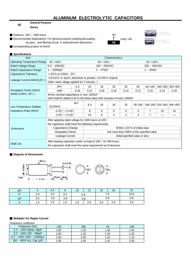
General PurposeSeries
■ Features: 105℃ 1000 hours SH■ Recommended Applications: For general purpose coupling,decoupling , Long Life by pass , and filtering circuit in entertainment electronics SE■Corresponding product to RoHS
■ Specifications
Rated Capacitance Range Capacitance Tolerance
(After rated voltage applied for 2 minutes )
6.3 10 16 25 35 50 63~100 160~250 350~4500.26 0.22 0.18 0.16 0.14 0.12 0.10 0.15 0.20
8 6 5 3 3 7 10 1510 8 6 4 3 7 — —
the capacitors shall meet the following requirements.
the capacitors shall meet the same requirement as Endurance.
■ Diagram of Dimensions
ψD 5 8 10 13 16 18P 2.0 3.5ψd 0.5 0.6a 1.5 1.5 1.5 2.0 2.0 2.0
■ Multiplier for Ripple Current
Frequency coefficient
1 ~ 150μF1 ~ 15000μF 1 ~ 470μF
I=0.01CV or 3(μA) ,whichever is greater. I=0.03CV+10(μA)
WV Z(120Hz)
1K1.30
Dissipation Factor
Z-40℃ / Z+20℃
Within ± 20 % of initial value
Low Temperature Stability
WVtanδ
Z-25℃ / Z+20℃
When nominal capacitance is over 1000uF,tanδ shall be added 0.02 to the listed value with increase of every 1000uF。
Capacitance ChangeNot more than 200% of the specified value
0.6
2210.00.8
7.5
1.5
300
2.56.3
5.0
350 ~ 450VDC6.3 ~ 100VDC 160 ~ 250VDC
After applying rated voltage for 1000 hours at 105℃
Frequency (Hz)
Operating Temperature Range
Dissipation Factor (MAX) (tanδ) (120Hz ,20℃)
6.3 ~ 100V Below 68μF
Characteristics -25~+105℃ -40~+105℃ -40~+105℃
120
0.5
1.001.001.00
Item
6.3 ~ 100V 100 ~ 680μF6.3 ~ 100V 1000 ~ 22000μF
Rated Voltage Range
Endurance
Impedance Ratio (MAX)
16 25
SE
1.051.10
1.00 1.20
ALUMINUM ELECTROLYTIC CAPACITORS
Shelf Life
Leakage Current (MAX)(20℃)
After leaving capacitors under no load at 105℃ for 500 hours.
Leakage Current
6.3 10
initial specified value or less
0.8
10K
1.50
1.151.10
1.251.15
160 ~ 450V ALL Cap (μF)
1.45
1.05 1.10
2.0
± 20 % at 120Hz , 20℃
35~100 160~250 315~350 400~450

General PurposeSeries
■Dimensions,Rated Ripple Current
Size Ripple Size Ripple Size Ripple Size Ripple Size Ripple Size Ripple Size Ripple1.0 5x11 12 5x11 132.2 5x11 18 5x11 203.3 5x11 25 5x11 274.7 5x11 20 5x11 25 5x11 30 5x11 346.8 5x11 25 5x11 30 5x11 32 5x11 3710 5x11 25 5x11 30 5x11 40 5x11 50 5x11 5515 5x11 40 5x11 45 5x11 50 5x11 60 5x11 6522 5x11 45 5x11 55 5x11 60 5x11 65 5x11 75 6.3x11 9033 5x11 60 5x11 70 5x11 75 5x11 85 5x11 95 6.3x11 11047 5X11 60 5x11 75 5x11 85 5x11 90 5x11 95 6.3x11 105 8x11 15568 5x11 75 5x11 80 5x11 100 6.3x11 125 6.3x11 125 8x11 159
5x11 100 5x11 110 5x11 110 6.3x11 145 6.3x11 150 8x11 160 8X15 230 10x12.5 260
150 5x11 120 5x11 110 6.3x11 175 8x11 200 8x11 200 10x12.5 289 10x15 3305x11 140 6.3x11 180 6.3x11 180 8x11 200 8x11 230 10x12.5 340 10x15 400
6.3x11 165 10x12.5 315 10x20 4606.3x11 160 6.3x11 205 8x11 285 8x11 265 8X15 345 10x20 535 10x20 520
8X15 320 10x12.5 3806.3x11 220 6.3x11 245 8x11 310 8X15 365 10x15 415 10x20 580 13x20 700
8x11 305 13x20 7308x11 255 8x11 335 10x12.5 455 10x15 650 10x20 680 13x25 860 13x25 840
10x12.5 4208x11 370 8X15 450 8x20 600 10x20 680 13x20 850 13x25 930 16x25 1020
10x12.5 470 10x12.5 490 10x15 59010x15 600 10x20 750 10x20 680 13x20 880 13x25 935 16x25 1220 16x32 1300
2200 10x20 740 10x20 800 13x20 990 13x25 1030 16x25 1230 16x36 1360 18x36 145513x20 1100 10x25 950 13x25 1140 16x25 1230 16x36 1470 18x36 1540
13x20 10504700 13x25 1100 13x25 1190 16x25 1330 16x32 1420 18x36 15806800 13x25 1250 16x25 1370 16x32 1580 18x36 1850
10000 16x25 1560 16x36 1760 18x36 215015000 18x32 2100 18x36 2150
SECapacitance
(μF)
ALUMINUM ELECTROLYTIC CAPACITORS
220
Rated (Surge) Voltage
35 (44) 50 (63) 63 (79)6.3 (8) 10 (13)
☆ Size: Dψx L (mm) ☆ Ripple Current: (mA/rms). 105℃,120Hz
1000
1500
3300
16 (20) 25 (32)
680
100
330
470

General PurposeSeries
■Dimensions,Rated Ripple Current
Size Ripple Size Ripple Size Ripple Size Ripple Size Ripple Size Ripple Size Ripple5x11 15 5x11 17 5x11 19 6.3x11 19 6.3x11 20 6.3x11 16 6.3x11 16
8x11 20 8x11 205x11 22 6.3x11 25 6.3x11 22 6.3x11 23 8x11 35 6.3x11 20 8x11 28
8x11 28 10x12.5 353.3 5x11 29 6.3x11 30 6.3x11 32 8x11 33 8x11 37 8x11 38 10x12.5 49
5x11 37 6.3x11 34 8x11 40 8x11 41 8X11 47 8x11 40 10x12.5 5510x12.5 49
5x11 46 8X11 50 8X11 56 8X11 57 8x15 50 10x15 6510x12.5 52
5x11 55 8x11 56 10x12.5 69 10x12.5 78 10x15 95 10x15 65 10x20 756.3x11 65
15 6.3x11 72 10x12.5 80 10x15 110 10x15 120 10x20 140 10x20 100 13X20 12522 8x11 115 10x15 130 10x15 140 10x20 155 13x20 165 13x20 150 13x25 160
8x11 120 10x20 180 10x20 190 13x20 170 13x25 220 13x25 190 16x25 21016x20 195
10x12.5 180 10X20 230 13x20 240 13x25 330 16x25 340 16x25 280 16x32 27018x20 275
10x15 241 13X20 270 13x25 330 13x25 340 16x32 320 18x32 30518x25 305
100 10x20 385 13x25 330 16x25 410 16x25 415 18x32 430 18x32 430 18x36 380120 18x32 440150 13x20 414 16x25 410 16x32 430 16X32 435 18x40 480 18X36 450
18X40 460180 18X45 480
13x25 590 16x32 550 16X36 520 18X36 600 18x32 520
330 13x25 600 18x36 770 18x36 705 470 16x25 740 18X40 800680 16x36 1200
1000 18x40 1340☆ Size: Dψx L (mm) ☆ Ripple Current: (mA/rms). 105℃,120Hz
1.0
350 (400)
SECapacitance
(μF)
Rated (Surge) Voltage
100 (125) 160 (200) 200 (250) 250 (300) 400 (450)
ALUMINUM ELECTROLYTIC CAPACITORS
220
33
68
6.8
47
10
4.7
2.2
450 (500)
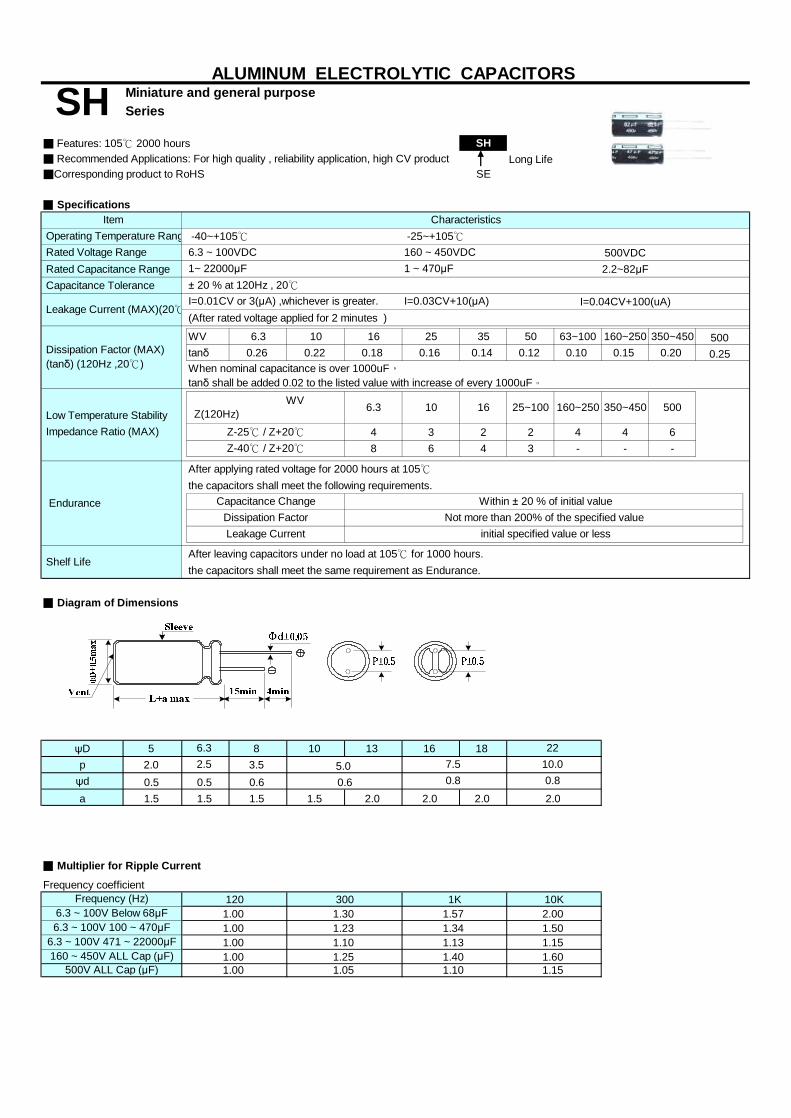
Miniature and general purposeSeries
■ Features: 105℃ 2000 hours SH■ Recommended Applications: For high quality , reliability application, high CV product Long Life■Corresponding product to RoHS SE
■ Specifications
500VDC
Rated Capacitance Range 2.2~82μF Capacitance Tolerance
I=0.04CV+100(uA)(After rated voltage applied for 2 minutes )
WV 6.3 10 16 25 35 50 63~100 160~250 350~450 500tanδ 0.26 0.22 0.18 0.16 0.14 0.12 0.10 0.15 0.20 0.25
4 3 2 2 4 4 68 6 4 3 - - -
the capacitors shall meet the following requirements.
the capacitors shall meet the same requirement as Endurance.
■ Diagram of Dimensions
ψD 5 8 10 13 16 18p 2.0 3.5ψd 0.5 0.6a 1.5 1.5 1.5 2.0 2.0 2.0
■ Multiplier for Ripple Current
Frequency coefficient
1.40
300
1.5
120
1.231.001.00
1.00
1.34
1K
6.3 ~ 100V 100 ~ 470μF
Frequency (Hz)6.3 ~ 100V Below 68μF
0.5 0.8
1.30 1.57
ALUMINUM ELECTROLYTIC CAPACITORS
Low Temperature Stability Impedance Ratio (MAX)
Dissipation Factor (MAX) (tanδ) (120Hz ,20℃)
Rated Voltage Range 160 ~ 450VDC
SH
Item
6.3 WV Z(120Hz) 10
When nominal capacitance is over 1000uF,tanδ shall be added 0.02 to the listed value with increase of every 1000uF。
I=0.03CV+10(μA)
50025~100 160~250
Characteristics -40~+105℃ Operating Temperature Range
Leakage Current (MAX)(20℃
-25~+105℃
1 ~ 470μF
I=0.01CV or 3(μA) ,whichever is greater.± 20 % at 120Hz , 20℃
6.3 ~ 100VDC1~ 22000μF
Shelf Life
initial specified value or less
After leaving capacitors under no load at 105℃ for 1000 hours.
Endurance Within ± 20 % of initial valueNot more than 200% of the specified value
Capacitance ChangeDissipation FactorLeakage Current
6.310.00.8
Z-25℃ / Z+20℃Z-40℃ / Z+20℃
2.5
After applying rated voltage for 2000 hours at 105℃
7.522
0.6
350~45016
1.15
2.0
5.0
1.101.60
10K2.001.501.15
160 ~ 450V ALL Cap (μF)500V ALL Cap (μF) 1.00 1.05
1.256.3 ~ 100V 471 ~ 22000μF 1.101.00 1.13
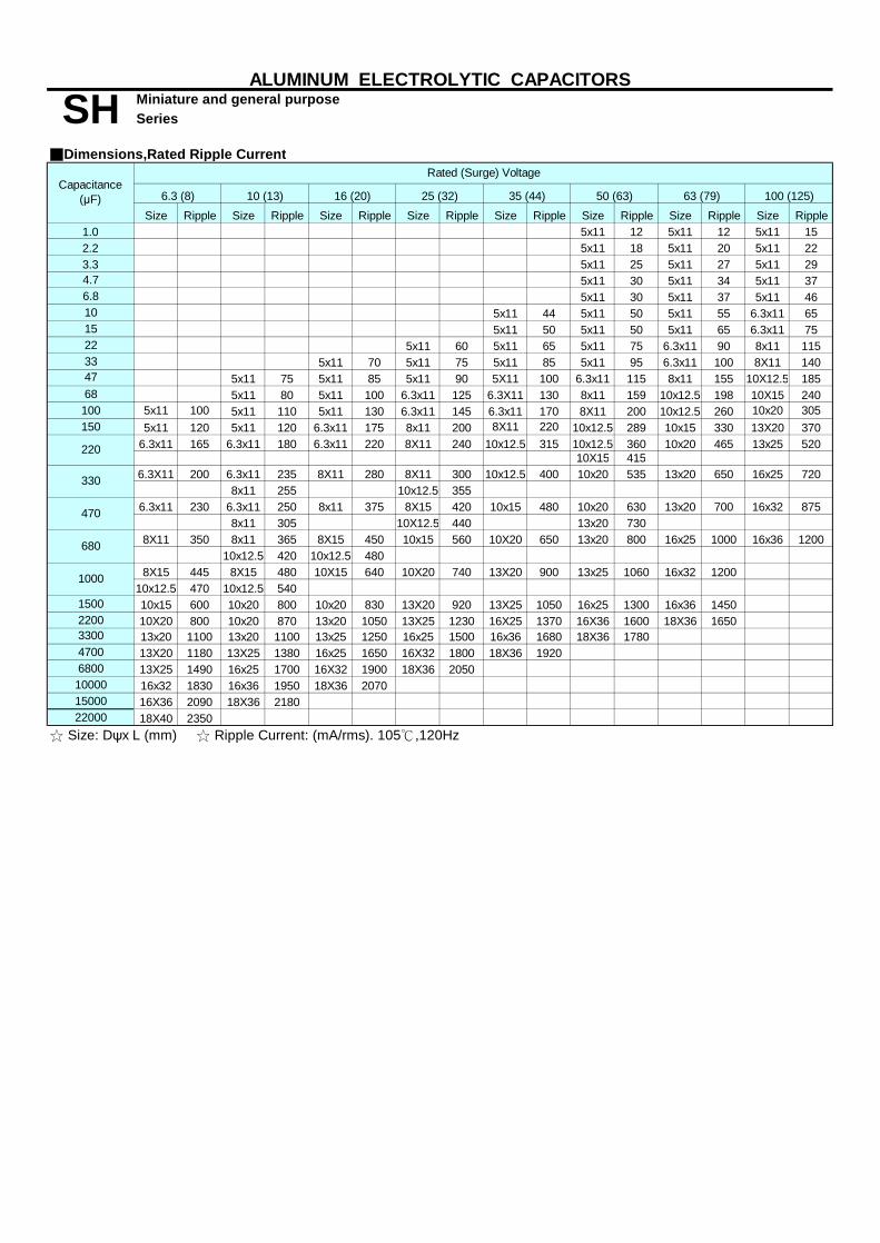
Miniature and general purposeSeries
■Dimensions,Rated Ripple Current
Size Ripple Size Ripple Size Ripple Size Ripple Size Ripple Size Ripple Size Ripple Size Ripple1.0 5x11 12 5x11 12 5x11 152.2 5x11 18 5x11 20 5x11 223.3 5x11 25 5x11 27 5x11 294.7 5x11 30 5x11 34 5x11 376.8 5x11 30 5x11 37 5x11 4610 5x11 44 5x11 50 5x11 55 6.3x11 6515 5x11 50 5x11 50 5x11 65 6.3x11 7522 5x11 60 5x11 65 5x11 75 6.3x11 90 8x11 11533 5x11 70 5x11 75 5x11 85 5x11 95 6.3x11 100 8X11 140
5x11 75 5x11 85 5x11 90 5X11 100 6.3x11 115 8x11 155 10X12.5 18568 5x11 80 5x11 100 6.3x11 125 6.3X11 130 8x11 159 10x12.5 198 10X15 240100 5x11 100 5x11 110 5x11 130 6.3x11 145 6.3x11 170 8X11 200 10x12.5 260 10x20 305150 5x11 120 5x11 120 6.3x11 175 8x11 200 8X11 220 10x12.5 289 10x15 330 13X20 370
6.3x11 165 6.3x11 180 6.3x11 220 8X11 240 10x12.5 315 10x12.5 360 10x20 465 13x25 520 10X15 415
6.3X11 200 6.3x11 235 8X11 280 8X11 300 10x12.5 400 10x20 535 13x20 650 16x25 7208x11 255 10x12.5 355
6.3x11 230 6.3x11 250 8x11 375 8X15 420 10x15 480 10x20 630 13x20 700 16x32 8758x11 305 10X12.5 440 13x20 730
8X11 350 8x11 365 8X15 450 10x15 560 10X20 650 13x20 800 16x25 1000 16x36 120010x12.5 420 10x12.5 480
8X15 445 8X15 480 10X15 640 10X20 740 13X20 900 13x25 1060 16x32 120010x12.5 470 10x12.5 540
1500 10x15 600 10x20 800 10x20 830 13X20 920 13X25 1050 16x25 1300 16x36 14502200 10X20 800 10x20 870 13x20 1050 13X25 1230 16X25 1370 16X36 1600 18X36 1650
13x20 1100 13x20 1100 13x25 1250 16x25 1500 16x36 1680 18X36 17804700 13X20 1180 13X25 1380 16x25 1650 16X32 1800 18X36 1920 6800 13X25 1490 16x25 1700 16X32 1900 18X36 2050 10000 16x32 1830 16x36 1950 18X36 207015000 16X36 2090 18X36 218022000 18X40 2350
50 (63)
☆ Size: Dψx L (mm) ☆ Ripple Current: (mA/rms). 105℃,120Hz
330
470
1000
680
63 (79)
47
220
3300
ALUMINUM ELECTROLYTIC CAPACITORS
100 (125)
Rated (Surge) Voltage
SHCapacitance
(μF) 6.3 (8) 10 (13) 16 (20) 25 (32) 35 (44)

Miniature and general purposeSeries
■Dimensions,Rated Ripple Current
Size Ripple Size Ripple Size Ripple Size Ripple Size Ripple Size Ripple Size Ripple Size Ripple5x11 17 6.3x11 17 6.3x11 17 6.3x11 16 6.3x11 17 6.3x11 17 6.3x11 18
8x11 226.3x11 25 6.3x11 25 6.3x11 29 8x11 31 8x11 31 8x11 29 8x11 30 8x11 25
10x12.5 376.3x11 36 6.3x11 36 8X11 42 8x11 35 8x11 35 8x11 34 8X15 42 8X16 30
10x12.5 406.3x11 43 8x11 50 8x11 52 8x11 45 8x11 45 10X12.5 55 10x12.5 52 8X16 34
10X12.5 55 10X12.5 388X11 54 8X11 60 8x11 62 8X15 60 10X15 68 10X15 62 10X16 50
10X12.5 658.2 10X20 65
8X11 70 10X12.5 80 10x12.5 80 10x15 80 10X15 80 10X20 98 10X20 85 10X20 7013x20 85
15 10X12.5 90 10x15 110 10X15 110 10X20 100 13X20 130 13X20 120 13X25 10010X15 115 10x20 140 10X20 140 13X20 150 13x20 150 13X25 155 13X25 150 13X25 115
16X25 13033 10X20 160 13x20 200 13X20 200 13X25 200 13X25 200 16x25 205 16X25 210 18X25 180
10x20 195 13x20 220 13X25 240 16X25 260 16x25 265 16x25 235 16X25 260 16X32 18018X30 230
13x20 255 13x25 280 13x25 290 16X32 410 16X32 400 18X32 370 18X32 25018x25 390 18x25 380 18X36 290
82 18X40 335100 13X25 350 16x25 350 16X25 380 18x32 400 18X32 500 18X36 490 18X36 495
18X32 520 18x40 530 18X40 56518x36 550
150 16X25 435 16x32 480 16X32 420 18x40 620 18x45 570 18X45 65016x32 550 16x36 675 18X36 680
18X32 68518x36 800 18x36 750
470 18x40 900680
10
☆ Size: Dψx L (mm) ☆ Ripple Current: (mA/rms). 105℃,120Hz
SH
220
Rated (Surge) Voltage
47
22
330
68
120
4.7
6.8
ALUMINUM ELECTROLYTIC CAPACITORS
450 (500)
1.0
2.2
Capacitance(μF) 500 (550)160 (200) 200 (250) 250 (300) 350 (400) 400 (450) 420 (470)
3.3
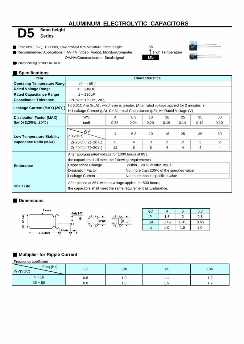
5mm heightSeries
■ Features : 85℃,1000hrs, Low profile/Ultra Miniature, 5mm height S5■ Recommended Applications : AV(TV, Video, Audio), Monitor/Computer,
D5■Corresponding product to RoHS
■ Specifications
-40 ~ +85℃4 ~ 50VDC
Rated Capacitance Range 1 ~ 220μF Capacitance Tolerance ± 20 % at 120Hz , 20℃
I≦0.01CV or 3(μA) , whichever is greater. (After rated voltage applied for 2 minutes )I= Leakage Current (μA) C= Nominal Capacitance (μF) V= Rated Voltage (V)
WV 4 6.3 10 16 25 35 50tanδ 0.35 0.24 0.20 0.16 0.14 0.12 0.10
Z(-25℃) / Z(+20℃) 6 4 3 2 2 2 2Z(-40℃) / Z(+20℃) 12 8 6 4 4 4 4
the capacitors shall meet the following requirements.
the capacitors shall meet the same requirement as Endurance.
■ Dimensions
ψD 4 5 6.3P 1.5 2 2.5ψd 0.45 0.45 0.45a 1.0 1.0 1.0
■ Multiplier for Ripple Current Frequency coefficient
25 ~ 500.80.8
Shelf LifeAfter placed at 85℃without voltage applied for 500 hours,
1.5 1.7
120 1K 10K Freq.(Hz) WV(VDC) 50
1.24 ~ 16 1.0 1.1
Within ± 20 % of initial valueNot more than 200% of the specified valueNot more than in specified value
1.0
Dissipation FactorLeakage Current
ALUMINUM ELECTROLYTIC CAPACITORS
Dissipation Factor (MAX) (tanδ) (120Hz ,20℃ )
Characteristics Operating Temperature Range
Leakage Current (MAX) (20℃ )
High Temperature
WVZ(120Hz) 4 6.3 10 16 35 50
After applying rated voltage for 1000 hours at 85℃
D5
25
OA/HA/Communication, Small signal
Endurance Capacitance Change
Item
Rated Voltage Range
Low Temperature Stability Impedance Ratio (MAX)

5mm heightSeries
Size Ripple Size Ripple Size Ripple Size Ripple Size Ripple Size Ripple Size Ripple
1 4x5 10
2.2 4x5 15
3.3 4x5 20
4.7 4x5 10 4x5 15 4x5 20 5x5 25
10 4x5 20 4x5 20 4x5 25 4x5 30 5x5 35 6.3x5 40
22 4x5 25 4x5 30 5x5 30 5x5 35 5x5 40 6.3x5 55 6.3x5 60
33 4x5 30 5x5 35 5x5 40 5x5 45 6.3x5 60
47 5x5 35 5x5 40 6.3x5 50 6.3x5 60
100 6.3x5 60 6.3x5 70 6.3x5 75 6.3x5 95
220 6.3x5 80 6.3x5 95
☆ Size: Dψx L (mm) ☆ Ripple Current : mA/rms,85℃,120Hz
ALUMINUM ELECTROLYTIC CAPACITORS
25 (32) 35 (44)
■Dimensions,Rated Ripple Current
D5Capacitance
(μF) 4 (5) 6.3 (8) 10 (13) 16 (20) 50 (63)
Rated (Surge) Voltage

5mm heightSeries
■ Features: 105℃ 1000 hours , 5.0mm height S5■ Recommended Applications: Applicable for VTR , Camera , Car Audio , Miniaudio and other industrial /commercial applications D5■Corresponding product to RoHS
■ Specifications
-40 ~ +105℃4 ~ 50VDC
Rated Capacitance Range 1 ~ 470μF Capacitance Tolerance ± 20 % at 120Hz , 20℃ Leakage Current (MAX) (20℃) I=0.01CV or 3(μA) , whichever is greater. (After rated voltage applied for 2 minutes )
WV 4 6.3 10 16 25 35 50tanδ 0.35 0.24 0.20 0.17 0.15 0.12 0.10
Z(-25℃) / Z(+20℃) 6 4 3 2 2 2 2Z(-40℃) / Z(+20℃) 12 8 6 4 4 3 3
the capacitors shall meet the following requirements.
the capacitors shall meet the same requirement as Endurance.
■ Dimensions
ψD 4.0 5.0 6.3 8.0P 1.5 2.0 2.5 3.5ψda
■ Multiplier for Ripple CurrentFrequency coefficient
50
Impedance Ratio (MAX)
WVZ(120Hz)
Characteristics Item Operating Temperature Range Rated Voltage Range
Dissipation Factor (MAX) (tanδ) (120Hz ,20℃)
16 Low Temperature Stability
Frequency (Hz) 10K1K300
Leakage Current
0.451.0
initial specified value or less
1~47μF100~330μF 1.20
1.20 1.30 1.501.10 1.15
1.001.00
120
25 354 6.3 10
Within ± 20 % of initial valueNot more than 200% of the specified valueDissipation Factor
High Temperature
ALUMINUM ELECTROLYTIC CAPACITORS
After placed at 105℃without voltage applied for 500 hours,
Endurance Capacitance Change
After apply rated voltage for 1000 hrs at 105℃ ,
Shelf Life
S5
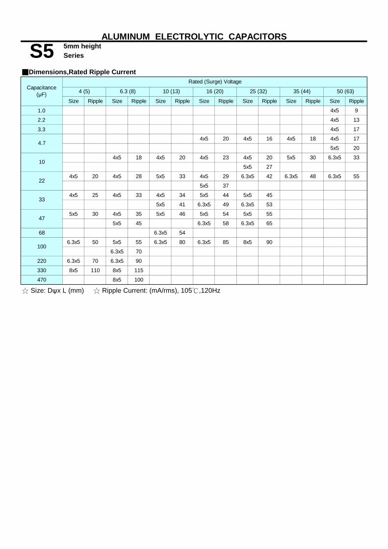
5mm heightSeries
Size Ripple Size Ripple Size Ripple Size Ripple Size Ripple Size Ripple Size Ripple
1.0 4x5 9
2.2 4x5 13
3.3 4x5 17
4x5 20 4x5 16 4x5 18 4x5 17
5x5 20
4x5 18 4x5 20 4x5 23 4x5 20 5x5 30 6.3x5 33
5x5 27
4x5 20 4x5 28 5x5 33 4x5 29 6.3x5 42 6.3x5 48 6.3x5 55
5x5 37
4x5 25 4x5 33 4x5 34 5x5 44 5x5 45
5x5 41 6.3x5 49 6.3x5 53
5x5 30 4x5 35 5x5 46 5x5 54 5x5 55
5x5 45 6.3x5 58 6.3x5 65
68 6.3x5 54
6.3x5 50 5x5 55 6.3x5 80 6.3x5 85 8x5 90
6.3x5 70
220 6.3x5 70 6.3x5 90
330 8x5 110 8x5 115
470 8x5 100
☆ Size: Dψx L (mm) ☆ Ripple Current: (mA/rms), 105℃,120Hz
50 (63)
■Dimensions,Rated Ripple Current
47
100
4.7
10
22
33
4 (5)
ALUMINUM ELECTROLYTIC CAPACITORS
S5Rated (Surge) Voltage
Capacitance(μF) 6.3 (8) 10 (13) 16 (20) 25 (32) 35 (44)

5mm heightSeries
■ Features:105℃ 2000 hours , Higher temperature range, long life than S5 H5Long Life
■ Recommended Applications: Monitor/Computer, AV(TV,Video,Audio), S5
■Corresponding product to RoHS
■ Specifications
-40 ~ +105℃4 ~ 50VDC
Rated Capacitance Range 1 ~ 330μF Capacitance Tolerance ± 20 % at 120Hz , 20℃
I=0.01CV or 3(μA) , whichever is greater. (After rated voltage applied for 2 minutes )
I= Leakage Current (μA) C= Nominal Capacitance (μF) V= Rated Voltage (V) (20℃)
WV 4 6.3 10 16 25 35 50tanδ 0.37 0.26 0.24 0.20 0.16 0.13 0.12
Down size tanδ add 3%.
Z-25℃ / Z+20℃ 6 4 3 2 2 2 2
Z-40℃ / Z+20℃ 12 8 6 4 4 4 4
After applying rated voltage for 2000 hours at 105℃
After placed at 105℃without voltage applied for 1000 hours,
■ Diagram of Dimensions
ψD 4.0 5.0 6.3 8.0P 1.5 2.0 2.5 3.5ψd 0.45 0.45 0.45 0.45a 1.0 1.0 1.0 1.0
■ Multiplier for Ripple CurrentFrequency coefficient
25
1.001.00 1.10 1.20
35
120 1K 10K
Not more than 200% of the specified value initial specified value or less
25~50
OA/HA/Communication, Small signal
Freq. (Hz)WV(VDC)
4~16
50
0.80
Load Life Within ± 20 % of initial value
1.50 1.70
Low Temperature Stability Impedance Ratio (MAX)
Leakage Current
Capacitance Change
Shelf Life
Dissipation Factor
ALUMINUM ELECTROLYTIC CAPACITORS
Dissipation Factor (MAX) (tanδ) (120Hz ,20℃)
Characteristics Operating Temperature Range
H5
Item
Rated Voltage Range
Leakage Current (MAX) (20℃)
Low profile/miniature, 5mm height
0.80
the capacitors shall meet the same requirement as load life.
WVZ(120Hz) 4 6.3
the capacitors shall meet the following requirements.
5010 16

5mm heightSeries
Size Ripple Size Ripple Size Ripple Size Ripple Size Ripple Size Ripple Size Ripple
1.0 4x5 10
2.2 4x5 15
3.3 4x5 15
4.7 4x5 10 4x5 15 4x5 15 5x5 20
10 4X5 15 4X5 20 4x5 20 4x5 25 5x5 30 6.3X5 35
22 4X5 20 4X5 25 5X5 25 5x5 30 6.3X5 40 6.3X5 45 6.3X5 55
33 4X5 25 5X5 30 5X5 35 5x5 40 6.3X5 50
47 5X5 30 5X5 35 6.3X5 45 6.3X5 55
100 6.3X5 50 6.3X5 60 6.3X5 70 6.3X5 90
220 6.3X5 70 8X5 95
330 8X5 110 8X5 120
25 (32)
Rated (Surge) Voltage
4 (5)
ALUMINUM ELECTROLYTIC CAPACITORS
■Dimensions,Rated Ripple Current
35 (44) 50 (63)
☆ Size: Dψx L (mm) ☆ Ripple Current: (mA/rms), 105℃,120Hz
H5Capacitance
(μF) 6.3 (8) 10 (13) 16 (20)

7mm/9mm heightSeries
■ Features: 85℃,1000hrs, Low profile/Miniature, 7mm/9mm height S7■ Recommended Applications: AV(TV, Video, Audio), Monitor/Computer,
D7■Corresponding product to RoHS
■ Specifications
-40 ~ +85℃4 ~ 63VDC
Rated Capacitance Range 1 ~ 470μF Capacitance Tolerance ± 20 % at 120Hz , 20℃
I≦0.01CV or 3(μA) , whichever is greater. (After rated voltage applied for 2 minutes )I= Leakage Current (μA) C= Nominal Capacitance (μF) V= Rated Voltage (V)
WV 4 6.3 10 16 25 35 50 63tanδ 0.35 0.24 0.20 0.16 0.14 0.12 0.10 0.08
Z(-25℃) / Z(+20℃) 6 4 3 2 2 2 2 2Z(-40℃) / Z(+20℃) 12 8 6 4 4 4 4 4
the capacitors shall meet the following requirements.
the capacitors shall meet the same requirement as Endurance.
■ Dimensions
ψD 4 5 6.3 8P 1.5 2 2.5 3.5ψd 0.45 0.45 0.45 0.5a 1.0 1.0 1.0 1.0
■ Multiplier for Ripple Current
Frequency coefficient
1.9
4 ~ 1625 ~3550 ~ 63
1.1 1.21.5 1.7
0.81.0
Not more than in specified value
0.80.8
1.61.0
1.0
Freq.(Hz) WV(VDC) 50 120 1K
636.3 10
10K
After placed at 85℃without voltage applied for 500 hours,
ALUMINUM ELECTROLYTIC CAPACITORS
Dissipation Factor (MAX) (tanδ) (120Hz ,20℃ )
Characteristics Operating Temperature Range
D7OA/HA/Communication, Small signal
Leakage Current (MAX) (20℃ )
Item
Rated Voltage Range
Low Temperature Stability WVZ(120Hz) 5016 25 354
High Temperature
Shelf Life
Leakage Current
Impedance Ratio (MAX)
Endurance Capacitance Change
After applying rated voltage for 1000 hours at 85℃
Dissipation Factor Within ± 20 % of initial valueNot more than 200% of the specified value
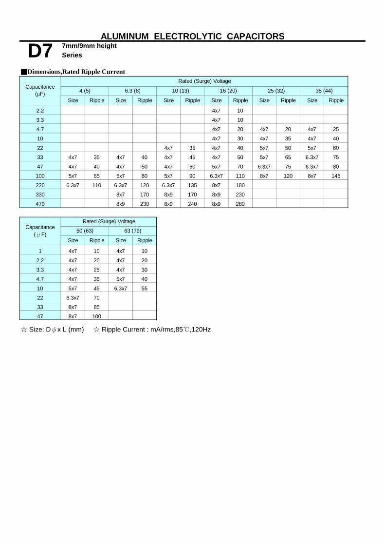
7mm/9mm heightSeries
Size Ripple Size Ripple Size Ripple Size Ripple Size Ripple Size Ripple
2.2 4x7 10
3.3 4x7 10
4.7 4x7 20 4x7 20 4x7 25
10 4x7 30 4x7 35 4x7 40
22 4x7 35 4x7 40 5x7 50 5x7 60
33 4x7 35 4x7 40 4x7 45 4x7 50 5x7 65 6.3x7 75
47 4x7 40 4x7 50 4x7 60 5x7 70 6.3x7 75 6.3x7 80
100 5x7 65 5x7 80 5x7 90 6.3x7 110 8x7 120 8x7 145
220 6.3x7 110 6.3x7 120 6.3x7 135 8x7 180
330 8x7 170 8x9 170 8x9 230
470 8x9 230 8x9 240 8x9 280
Size Ripple Size Ripple
1 4x7 10 4x7 10
2.2 4x7 20 4x7 20
3.3 4x7 25 4x7 30
4.7 4x7 35 5x7 40
10 5x7 45 6.3x7 55
22 6.3x7 70
33 8x7 85
47 8x7 100
☆ Size: Dψx L (mm) ☆ Ripple Current : mA/rms,85℃,120Hz
63 (79)
ALUMINUM ELECTROLYTIC CAPACITORS
25 (32) 35 (44)
■Dimensions,Rated Ripple CurrentRated (Surge) Voltage
D7Capacitance
(μF) 4 (5) 6.3 (8) 10 (13) 16 (20)
Capacitance(μF)
Rated (Surge) Voltage
50 (63)

7mm heightSeries
■ Features : 105℃ 1000 hours , 7.0/9.0mm height S7■ Recommended Applications : For Portable Micro Computer , Disk Driver , D7■Corresponding product to RoHS
■ Specifications
-40 ~ +105℃4 ~ 63VDC
Rated Capacitance Range 1 ~ 470μF Capacitance Tolerance ± 20 % at 120Hz , 20℃ Leakage Current (MAX) (20℃) I=0.01CV or 3(μA) , whichever is greater. (After rated voltage applied for 2 minutes )
WV 4 6.3 10 16 25 35 50 63tanδ 0.35 0.24 0.20 0.17 0.15 0.12 0.10 0.08
Z-25℃ / Z+20℃ 6 4 3 2 2 2 2 2Z-40℃ / Z+20℃ 12 8 6 4 4 3 3 3
After applying rated voltage for 1000 hours at 105℃
After placed at 105℃without voltage applied for 500 hours,
■ Diagram of Dimensions
ψD 4.0 5.0 6.3 8.0P 1.5 2.0 2.5 3.5ψd 0.45 0.45 0.45 0.5a 1.0 1.0 1.0 1.0
■ Multiplier for Ripple Current
Frequency coefficientFrequency (Hz)
1~47μF100~330μF
Impedance Ratio (MAX)
WVZ(120Hz) 4
Rated Voltage Range
6.3 10
Shelf Life
Low Temperature Stability
0.75
Dissipation Factor
50 120
1.000.75 1.00
Endurancethe capacitors shall meet the following requirements.
35 50 6316 25
ALUMINUM ELECTROLYTIC CAPACITORS
Dissipation Factor (MAX) (tanδ) (120Hz ,20℃)
Characteristics Operating Temperature Range
S7
Item
Small Calculator and Audio equipment…etc High Temperature
1.10 1.15 1.20
300 1K 10K1.501.20 1.30
Within ± 20 % of initial value
Leakage Current
the capacitors shall meet the same requirement as Endurance.
Capacitance ChangeNot more than 200% of the specified value
initial specified value or less

7mm heightSeries
Size Ripple Size Ripple Size Ripple Size Ripple Size Ripple Size Ripple Size Ripple Size Ripple
1.0 4x7 10 4x7 13
2.2 4x7 7 4x7 19 4x7 21
3.3 4x7 13 4x7 24 4x7 26
4x7 19 4x7 24 4x7 24 4x7 29 4x7 26
5x7 24 5x7 31 6.3x7 33
4x7 29 4x7 33 4x7 34 4x7 37 5x7 42
5x7 35 5x7 36 5x7 45 6.3x7 50
6.3x7 35 6.3x7 45
4x7 37 4x7 31 4x7 36 4x7 43 5x7 48 6.3x7 65
5x7 38 5x7 44 5x7 51 6.3x7 57
6.3x7 53
4X7 30 5x7 42 4x7 39 4x7 50 5x7 55 6.3x7 70
5x7 47 5x7 57 6.3x7 65
4X7 35 4x7 46 4x7 50 5x7 75 5x7 67 6.3x7 81
5x7 55 5x7 60 6.3x7 77 6.3x7 79
6.3x7 60
68 5x7 84
5X7 55 5x7 75 5x7 85 5x7 94 6.3x7 120
6.3x7 90 6.3x7 100 6.3x7 110 8x7 120
150 6.3x7 120
6.3X7 95 6.3x7 130 6.3x7 135 8x7 140
8x9 140
330 8x7 140 8x9 155
470 8x9 165 8x9 165
ALUMINUM ELECTROLYTIC CAPACITORS
22
10
63 (79)
■Dimensions,Rated Ripple Current
100
47
35 (44) 50 (63)
Rated (Surge) Voltage
4 (5)
☆ Size: Dψx L (mm) ☆ Ripple Current: (mA/rms), 105℃,120Hz
S7
4.7
33
Capacitance(μF) 6.3 (8) 10 (13) 16 (20)
220
25 (32)

7mm/9mm heightSeries
■ Features : 105℃ 2000 hours , Higher temperature range, Long life than S7 Low profile/miniature, 7mm/9mm height H7■ Recommended Applications : Monitor/Computer, AV(TV,Video,Audio), OA/HA/Communication, Small signal S7■Corresponding product to RoHS
■ Specifications
-40 ~ +105℃4 ~ 63VDC
Rated Capacitance Range 1 ~ 470μF Capacitance Tolerance ± 20 % at 120Hz , 20℃
I=0.01CV or 3(μA) , whichever is greater. (After rated voltage applied for 2 minutes )
I= Leakage Current (μA) C= Nominal Capacitance (μF) V= Rated Voltage (V) (20℃)
WV 4 6.3 10 16 25 35 50 63tanδ 0.35 0.24 0.20 0.18 0.15 0.13 0.12 0.10
Down size tanδ add 3%.
Z-25℃ / Z+20℃ 6 4 3 2 2 2 2 2Z-40℃ / Z+20℃ 12 8 6 4 4 4 4 4
After applying rated voltage for 2000 hours at 105℃
After placed at 105℃without voltage applied for1000 hours,
■ Diagram of Dimensions
ψD 4.0 5.0 6.3 8.0P 1.5 2.0 2.5 3.5ψd 0.45 0.45 0.45 0.5a 1.0 1.0 1.0 1.0
■ Multiplier for Ripple Current
Frequency coefficient
25~3550~63
0.80.8
the capacitors shall meet the same requirement as load life.
WVZ(120Hz) 4 6.3
the capacitors shall meet the following requirements.
50 6310 16 25 35
1.01.0
ALUMINUM ELECTROLYTIC CAPACITORS
Dissipation Factor (MAX) (tanδ) (120Hz ,20℃)
Characteristics Operating Temperature Range
H7
Item
Rated Voltage Range
Leakage Current (MAX) (20℃)
Long Life
4~16
50
0.8
Load Life
Low Temperature Stability Impedance Ratio (MAX)
Leakage Current
Capacitance Change
120 1K 10K
Shelf Life
Dissipation Factor
Freq. (Hz)WV(VDC)
1.51.6
1.71.9
Within ± 20 % of initial valueNot more than 200% of the specified value
initial specified value or less
1.0 1.1 1.2

7mm/9mm heightSeries
Size Ripple Size Ripple Size Ripple Size Ripple Size Ripple Size Ripple Size Ripple Size Ripple
1.0 4x7 10 4x7 10
2.2 4x7 10 4x7 20 4x7 20
3.3 4x7 10 4x7 25 4x7 25
4.7 4x7 15 4x7 20 4x7 25 4x7 30 5x7 35
10 4x7 25 4x7 30 4x7 35 5x7 35 6.3x7 50
22 4x7 30 4x7 35 5x7 50 5x7 60 6.3x7 65
33 4X7 30 4x7 35 4x7 40 5x7 50 6.3x7 65 6.3x7 70 8x7 80
47 4X7 35 5x7 50 5x7 60 6.3x7 70 6.3x7 70 8x7 80 8x9 100
100 5X7 55 5x7 70 6.3x7 90 6.3x7 110 8x7 115 8x9 145
220 6.3X7 95 6.3x7 110 6.3x7 135 8x9 180
330 8x7 150 8x9 160 8x9 210
470 8x9 200 8x9 210
ALUMINUM ELECTROLYTIC CAPACITORS
63 (79)
■Dimensions,Rated Ripple Current
35 (44) 50 (63)
☆ Size: Dψx L (mm) ☆ Ripple Current: (mA/rms), 105℃,120Hz
H7Capacitance
(μF) 6.3 (8) 10 (13) 16 (20) 25 (32)
Rated (Surge) Voltage
4 (5)

Series
■ Features: 85℃,1000hrs, Non-polarized/Polarity reversing
■ Recommended Applications:
Small crossover network, Reversed polarity circuit, Coupling■Corresponding product to RoHS
■ Specifications
Rated Capacitance Range Capacitance Tolerance
I≦0.03CV+4μA ; L=7mm,I≦0.05CV or 10μA whichever is greater (After rated voltage applied for 2 minutes )I= Leakage Current (μA) C= Nominal Capacitance (μF) V= Rated Voltage (V)
4 6.3 10 16 25 35 50 63 80 100 160 200 2500.35 0.24 0.2 0.17 0.15 0.15 0.15 0.10 0.10 0.10 0.20 0.20 0.20
tanδ shall be added 0.02 to the listed value with increase of every 1000μF.
6 4 3 2 2 2 2 2 2 2 6 6 612 8 6 4 4 3 3 3 3 3 - - -
(The polarity shall be reversed every 250 hours)
the capacitors shall meet the same requirements as load life.
ψD 4 5 6.3 8 10 13 16 18
P 1.5 2.0 2.5 3.5 5.0 5.0 7.5 7.5( 0.45
)( 0.45)
0.5 0.5( 1.0 ) ( 1.0 )1.5 1.5
■ Multiplier for Ripple Current Frequency coefficient
0.45
0.81.0
0.6
50 ~ 100 0.8 1.0 1.60.8 1.5
1.2
0.8
Shelf LifeAfter placed at 85℃without voltage applied for 500 hours,
Freq.(Hz) WV(VDC) 1K120
■ Diagram of Dimensions
50
0.8
Non-polar
1.5 1.6
4 ~ 1625 ~35
160 ~ 250
1.11.7
1.0
160~250VDC1~100μF
1.01.9
ALUMINUM ELECTROLYTIC CAPACITORS
Dissipation Factor (MAX) (tanδ) (120Hz ,20℃)
Characteristics Operating Temperature Range
RN
Leakage Current (MAX) (20℃)
35 50
Item
Rated Voltage Range
4
-40 ~ +85℃4 ~ 100VDC1 ~ 6800μF± 20 % at 120Hz , 20℃
-25~+85℃
Low Temperature StabilityZ(-25℃) / Z(+20℃) Impedance Ratio (MAX)Z(-40℃) / Z(+20℃)
After applying rated voltage for 1000 hours at 85℃,the capacitors shall meet the following requirements.
10025106.3 16 200
WVtanδ
160
When nominal capacitance is over 1000μF
25063 WV Z(120Hz) 80
2.0
Not more than 200% of the specified valueNot more than the specified valueLeakage Current
Dissipation Factor
1.5
0.80.6ψd
Endurance Within ± 20 % of initial value
10K
0.6
2.0 2.0a 1.0 1.5
Capacitance Change
( ) : L = 7

Series
Size Ripple Size Ripple Size Ripple Size Ripple Size Ripple Size Ripple Size Ripple Size Ripple
4x7 10 4x7 15
5x11 10 5x11 10
4x7 15 4x7 20 5x7 25
5x11 20 5x11 20
4x7 15 5x7 20 5x7 25 6.3x7 30
5x11 30 5x11 30
5x7 25 6.3x7 30 6.3x7 35
4x7 20 5x7 20 5x11 30 5x11 30 6.3x11 35
5x7 30 5x11 40 5x11 40
4x7 25 5x11 40 6.3x7 35 6.3x7 40 6.3x11 45 6.3x11 55
5x7 40 5x11 55 6.3x7 50
5x7 35 5x11 50 6.3x7 45 6.3x11 65 6.3x11 70 8x11 80 8x11 90
5x7 35 5x7 40 5x11 65 5x11 70 6.3x7 65
5x11 60 6.3x7 50 6.3x7 60 6.3x11 80 8x11 100 8x11 105 10x12.5 135
5x11 70 5x11 75 6.3x7 70
5x7 40 6.3x7 50 6.3x7 60 6.3x11 95 6.3x11 95 8x11 120 8x15 140 10x16 180
100 6.3x7 60 6.3x11 115 6.3x11 125 8x11 160 8x11 160 10x16 230 10x20 265 13x20 320
220 8x11 205 8x11 215 10x12.5 275 10x16 305 13x20 410 13x25 480 16x25 575
330 8x11 265 10x16 345 10x16 375 13x20 450 13x20 505 16x25 650 16x32 750
470 10x12.5 370 10x16 410 10x20 485 13x20 540 13x25 655 16x32 835 18x36 965
1000 10x20 650 13x20 720 13x25 855 16x25 950 16x32 1140
2200 13x25 1160 16x25 1280 16x32 1510 18x36 1620
3300 16x25 1570 16x32 1690 18x36 1980
4700 16x32 2020 18x36 2160
6800 18x36 2600
Size Ripple Size Ripple Size Ripple Size Ripple Size Ripple
1 5x11 10 6.3x11 15 6.3x11 15 8x11 15
2.2 5x11 30 6.3x11 25 8x11 20 8x11 20 10x12.5 25
3.3 6.3x11 35 6.3x11 35 10x12.5 30 10x12.5 30 10x12.5 30
4.7 6.3x11 40 6.3x11 40 10x12.5 35 10x16 40 10x16 40
10 8x11 65 8x11 70 10x16 55 13x20 70 13x20 70
22 10x16 105 10x16 135 13x25 105 13x25 120 16x25 135
33 10x16 160 13x20 220 16x25 165 16x25 165 16x32 180
47 10x20 215 13x20 240 16x26 200 16x32 220 16x36 230
100 13x25 385 16x25 425 18x36 360
220 16x32 690 18x36 720
330 18x36 860
☆ Size: Dψx L (mm) ☆ Ripple Current : mArms/85℃,120Hz
80 (100)
1.0
2.2
3.3
4 (5)
33
47
22
10
4.7
160 (200)
ALUMINUM ELECTROLYTIC CAPACITORS
50 (63) 63 (79)
■Dimensions,Rated Ripple Current
25 (32) 35 (44)
250 (300)
Rated (Surge) Voltage
Rated (Surge) Voltage
RNCapacitance
(μF) 6.3 (8) 10 (13) 16 (20)
Capacitance(μF) 100 (125) 200 (250)
Non-polar

■ Features: 105℃ 1000 hours SN■Recommended Application: Non-polar miniature type for used in
reversing polarity DC voltage circuits RN■Corresponding product to RoHS
Rated Capacitance Range
WV 6.3 10 16 25 35 50 63 80 100 160 200 250tanδ 0.24 0.20 0.17 0.15 0.15 0.15 0.10 0.10 0.10 0.20 0.20 0.20
4 3 2 2 2 2 2 2 210 8 6 4 3 3 3 3 3
(The polarity shall be reversed every 250 hrs.)
■ Diagram of Dimensions
ψD 4.0 6.3 8.0 10.0 13.0 16.0 18.0P 1.5 2.5 3.5 5.0 5.0 7.5 7.5ψd 0.45 0.5 0.6 0.6 0.6 0.8 0.8a 1.0 1.5 1.5 1.5 2.0 2.0 2.0
■ Multiplier for Ripple CurrentFrequency coefficient
Z-25℃ / Z+20℃Z-40℃ / Z+20℃
10 16 25 35 Low Temperature Stability Impedance Ratio (MAX)
WV Z(120Hz)
After placed at 105℃ without voltage applied for 500 hours,
Endurance
Leakage Current
50
6-
6.3 80
Frequency (Hz)Factor
60 1200.75 1.00
Dissipation Factor (MAX) (tanδ) (120Hz ,20℃)
100
After applying rated voltage for 1000 hours at 105℃,
Shelf Life
Dissipation Factor Capacitance Change
ALUMINUM ELECTROLYTIC CAPACITORS
I=0.03CV+ 3μA; L=7mm, I=0.06CV+ 10μA(After rated voltage applied for 2 minutes ) Capacitance Tolerance
Rated Voltage Range1 ~ 2200 μF 1~100μF± 20 % at 120Hz , 20℃
Non-polar Series
Operating Temperature Range
Leakage Current (MAX) (20℃)
■ Specifications
SN
-40 ~ +105℃ -25~+105℃6.3 ~ 100VDC 160~250VDC
Item
63
When nominal capacitance is over 1000uF,tanδ shall be added 0.02 to the listed value with increase of every 1000uF;L=7mm, tanδ shall be added 0.03
160-250
2.0
10K
0.51.5
300 1K1.651.20 1.32
High Temperature
the capacitors shall meet the same requirement as Endurance.
Within ± 25 % of initial value Not more than 200% of specified value
5.0
Not more than the specified value
Characteristics
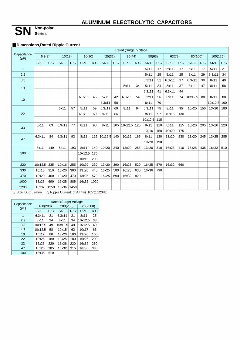
SIZE R.C SIZE R.C SIZE R.C SIZE R.C SIZE R.C SIZE R.C SIZE R.C SIZE R.C SIZE R.C
1 5x11 17 5x11 17 5x11 17 5x11 21
2.2 5x11 25 5x11 25 5x11 29 6.3x11 34
3.3 6.3x11 31 6.3x11 37 6.3x11 39 8x11 49
5x11 34 5x11 34 5x11 37 8x11 47 8x11 58
6.3x11 41 6.3x11 44
6.3x11 45 5x11 42 6.3x11 54 6.3x11 56 8x11 74 10x12.5 88 8x11 80
6.3x11 50 8x11 70 10x12.5 100
5x11 57 5x11 59 6.3x11 69 8x11 94 6.3x11 75 8x11 95 10x20 150 13x20 180
6.3x11 69 8x11 86 8x11 97 10x16 130
10x12.5 115
5x11 63 6.3x11 77 8x11 98 8x11 105 10x12.5 125 8x11 110 8x11 115 13x20 205 13x20 220
10x16 150 10x20 175
6.3x11 84 6.3x11 93 8x11 115 10x12.5 140 10x16 165 8x11 130 13x20 230 13x20 245 13x25 285
10x20 190
8x11 140 8x11 193 8x11 140 10x20 240 13x20 285 13x20 310 16x25 410 16x25 435 16x32 510
10x12.5 175
10x16 205
220 10x12.5 235 10x16 255 10x20 330 13x20 390 16x25 520 16x25 570 16x32 660
330 10x16 310 10x20 380 13x20 445 16x25 580 16x25 630 16x36 790
470 10x20 400 13x20 470 13x25 570 16x25 690 16x32 820
1000 13x25 690 16x25 885 16x32 1020
2200 16x32 1250 16x36 1450
SIZE R.C SIZE R.C SIZE R.C1 6.3x11 21 6.3x11 21 8x11 25
2.2 8x11 34 8x11 34 10x12.5 383.3 10x12.5 49 10x12.5 49 10x12.5 494.7 10x12.5 58 10x15 62 10x17 6610 10x17 80 13x20 100 13x20 10022 13x25 180 13x25 180 16x26 20033 16x26 220 16x26 220 16x32 25047 16x26 285 16x32 315 16x36 330100 18x36 510
☆ Size: Dψx L (mm) ☆ Ripple Current: (mA/rms). 105℃,120Hz
100(125)
47
35(44) 50(63) 63(79)
100
33
ALUMINUM ELECTROLYTIC CAPACITORS
6.3(8) 10(13) 16(20) 80(100)25(32)Capacitance(μF)
SN■Dimensions,Rated Ripple Current
Non-polar Series
Rated (Surge) Voltage
Capacitance(μF) 160(200) 200(250) 250(300)
Rated (Surge) Voltage
4.7
22
10
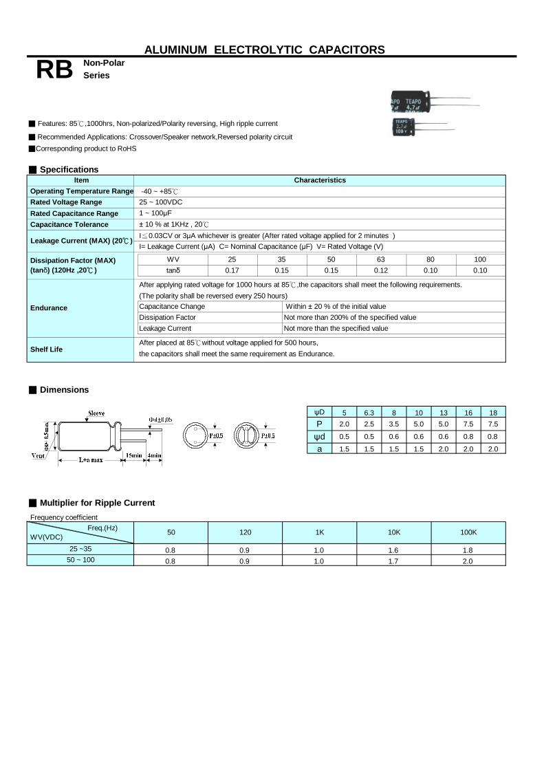
Non-PolarSeries
■ Features: 85℃,1000hrs, Non-polarized/Polarity reversing, High ripple current
■ Recommended Applications: Crossover/Speaker network,Reversed polarity circuit■Corresponding product to RoHS
■ Specifications
Rated Capacitance Range Capacitance Tolerance
I≦0.03CV or 3μA whichever is greater (After rated voltage applied for 2 minutes )I= Leakage Current (μA) C= Nominal Capacitance (μF) V= Rated Voltage (V)
(The polarity shall be reversed every 250 hours)
the capacitors shall meet the same requirement as Endurance.
■ Dimensions
ψD 5 6.3 8 10 13 16 18P 2.0 2.5 3.5 5.0 5.0 7.5 7.5
a 1.5 1.5 1.5 1.5 2.0 2.0 2.0
■ Multiplier for Ripple Current Frequency coefficient
Within ± 20 % of the initial valueNot more than 200% of the specified valueNot more than the specified value
0.8ψd 0.5 0.5 0.80.6 0.6
350.15
-40 ~ +85℃25 ~ 100VDC1 ~ 100μF± 10 % at 1KHz , 20℃
WVtanδ
Endurance
Item
Rated Voltage Range
250.17
After applying rated voltage for 1000 hours at 85℃,the capacitors shall meet the following requirements.
Dissipation FactorCapacitance Change
Leakage Current
0.12
ALUMINUM ELECTROLYTIC CAPACITORS
Dissipation Factor (MAX) (tanδ) (120Hz ,20℃ )
Characteristics Operating Temperature Range
RB
Leakage Current (MAX) (20℃ )
500.15
63
50 ~ 100 0.8 0.9 1.0
Shelf LifeAfter placed at 85℃without voltage applied for 500 hours,
Freq.(Hz) WV(VDC)
25 ~35 1.8
100K
80 1000.10 0.10
1.7 2.00.8 0.9 1.0
0.6
1.6
50 120 1K 10K

Series
Size Ripple Size Ripple Size Ripple Size Ripple Size Ripple Size Ripple
1 6.3x11 70
1.5 6.3x11 85
2.2 6.3x11 95 8x11 110
3.3 6.3x11 105 8x11 130 8x11 140
4.7 8x11 145 8x11 155 10x12.5 200
5.6 6.3x11 130 8x11 160 10x12.5 200 10x12.5 215
6.8 8x11 170 8x11 180 10x12.5 220 10x12.5 235
8.2 8x11 185 8x11 195 10x12.5 245 10x16 290
10 6.3x11 170 8x11 205 10x12.5 255 10x12.5 270 10x16 320
15 6.3x11 200 8x11 240 10x12.5 295 10x12.5 310 10x16 390 10x20 445
22 8x11 280 10x12.5 340 10x12.5 360 10x16 420 10x20 505 13x20 625
33 8x11 340 10x12.5 420 10x16 515 10x20 580 13x20 720 13x25 845
47 10x12.5 480 10x16 555 10x20 660 13x20 805 13x25 945 16x25 1155
56 10x12.5 520 10x16 640 13x20 835 13x20 880 13x25 1030 16x25 1260
68 10x16 635 10x16 705 13x20 920 13x25 1070 16x25 1300 16x32 1520
82 10x16 700 10x20 830 13x20 1010 13x25 1175 16x25 1430 16x36 1765
100 10x16 820 13x20 1065 13x25 1230 16x36 1480 16x36 1820 18x36 2080
☆ Size: Dψx L (mm) ☆ Ripple Current : mA/rms,85℃,1KHz
RB
Capacitance(μF) 25 (32) 80 (100)
Non-Polar
100 (125)
ALUMINUM ELECTROLYTIC CAPACITORS
50 (63) 63 (79)
■Dimensions,Rated Ripple CurrentRated (Surge) Voltage
35 (44)

■ Features: 85℃ 1000 hours
■Corresponding product to RoHS
25~ 50VDC
Rated Capacitance Range
ψD 16.0 18.0 22.0P 10.0
a
Frequency coefficient
After applying rated voltage for 1000hrs at 85℃, ( Polarity inverted every 250 hrs.)
13.0
2.2 ~ 47 μF
ALUMINUM ELECTROLYTIC CAPACITORS
Endurance
Characteristics
Dissipation Factor
-40 ~ +85℃ Item
50WV0.05 0.05 0.05
25~50 VFrequency (Hz)
Dissipation Factor (MAX) (tanδ) (120Hz ,20℃)
Shelf Life
■ Multiplier for Ripple Current
Series
Operating Temperature Range
■ Specifications
tanδ25 35
Leakage Current (MAX) (20℃) Capacitance Tolerance ± 10 %(K) at 120Hz , 20℃
DC Leakage current :100μA Max .(After 2 minutes both direction )
ψd
Capacitance Change Not more than 150% of specified value Not more than the specified value
SR
Rated Voltage Range
■Recommended Application:Non-polar capacirors for horizontal deflection circuits of TV sets,Correction at high frequency and high ripple currents
Bi-polar horizontal deflection
Within ± 20 % of initial value
Leakage Current
After placed at 85℃ without voltage applied for 500 hours,the capacitors shall meet the same requirement as Endurance.
the capacitors shall meet the following requirements.
0.6
■ Diagram of Dimensions
7.55.0
0.8 0.8
2.0
600.4
1200.4
400 ~ 1 K0.8
15.75 K1.0

SIZE RIPPLE SIZE RIPPLE SIZE RIPPLE
2.2 16X25 6 16X25 6 16X25 6
3.3 16X25 7 16X25 7 16X25 7
4.7 16X25 7 16X25 7 16X25 7
5.6 16X32 7 16X32 7 16X32 7
6.8 16X36 8 16X36 8 16X36 8
8.2 16X36 8 16X36 8 16X36 8
10 18X40 12 18X40 12 18X40 12
13 18X40 12 18X40 12 18X40 12
15 18X40 12 18X40 12 18X40 12
18 22X40 13 22X40 13 22X40 13
20 22X40 13 22X40 13 22X40 13
22 22X40 13 22X40 13 22X40 13
25 22X40 13 22X40 13 22X40 13
47 22X40 13 22X40 13 22X40 13
☆ Size: Dψx L (mm) ☆ Ripple Current: (Ap-p) / Sawtooth waveform 15.75KHz,85℃
ALUMINUM ELECTROLYTIC CAPACITORS
■Dimensions,Rated Ripple Current
25 ( 32 ) 35 ( 44 ) 50 ( 63 )
Rated (Surge) Voltage
Capacitance(μF)
SR Bi-polar horizontal deflectionSeries

Bi-PolarSeries
BX■ Features: 105℃,1000hrs, Bi-polarized/Polarity reversing High Temperature■ Recommended Applications: TV/Monitor, Horizontal deflection correction SR■Corresponding product to RoHS
■ Specifications
Rated Capacitance Range Capacitance Tolerance
I≦100μA (After rated voltage applied for 2 minutes )I= Leakage Current (μA)
(The polarity shall be reversed every 250 hours)
■ Dimensions
ψD 10 13 16 18 22 25P 5.0 5.0 7.5 7.5 10.0 12.5
a 1.5 2.0 2.0 2.0 2.0 2.0
■ Multiplier for Ripple CurrentFrequency coefficient
15.75 K25~50 V 0.4 0.4 0.8 1.0
Frequency (Hz) 60 120 400 ~ 1 K
0.05 0.05
Dissipation Factor Not more than 200% of the specified value
After applying rated voltage for 1000 hours at 105℃,the capacitors shall meet the following requirements.
Within ± 15 % of the initial value Endurance Capacitance Change
Leakage Current
After placed at 105℃without voltage applied for 500 hours,the capacitor shall meet the same requirement as Endurance.
ALUMINUM ELECTROLYTIC CAPACITORS
Dissipation Factor (MAX) (tanδ) (120Hz ,20℃)
Characteristics Operating Temperature Range
BX
Leakage Current (MAX) (20℃)
35tanδ 0.05
50
Shelf Life
Item
Rated Voltage Range
25
-40 ~ +105℃25 ~ 50VDC1 ~ 33 μF± 10 % ( K ) at 120Hz , 20℃
WV
Not more than the specified value
1.00.8ψd 0.6 0.6 0.8 0.8

Bi-PolarSeries
Size Ripple ESR Size Ripple ESR Size Ripple ESR
1 10x20 1.4 66.4
1.2 10x20 1.5 55.3 13x20 1.8 55.3
1.5 10x20 1.8 44.3 13x20 2.0 44.3
1.8 10x20 1.9 36.9 13x20 2.2 36.9 13x20 2.2 36.9
2.2 13x20 2.5 30.2 13x20 2.5 30.2 13x20 2.5 30.2
2.7 13x20 2.7 24.6 13x20 2.7 24.6 13x25 3.0 24.6
3.3 13x20 3.1 20.1 13x25 3.3 20.1 16x25 3.8 20.1
3.9 13x20 3.3 17 13x25 3.6 17 16x25 4.0 17.0
4.7 13x25 4.0 14.1 16x25 4.5 14.1 16x25 4.5 14.1
5.6 16x25 5.0 11.9 16x25 5.0 11.9 16x32 5.4 11.9
6.8 16x25 5.5 9.76 16x32 6.0 9.76 16x36 6.8 9.76
8.2 16x25 6.0 8.09 16x32 6.5 8.09 18x36 7.4 8.10
10 16x32 7.3 6.64 16x36 7.6 6.64 18x40 8.5 6.64
12 16x36 8.5 5.53 18x36 8.5 5.53 22x40 9.3 5.53
15 18x36 9.3 4.43 18x40 10 4.43 22x40 11 4.43
18 18x40 11 3.69 22x40 12 3.69 25x40 14 3.69
22 22x40 13 3.02 22x40 14 3.02 25x40 15 3.02
27 22x40 15 2.46 25x40 16 2.46
33 25x40 18 2.01
☆ Size: Dψx L (mm) ☆ Max Ripple Current [RC(Ap-p) / Sawtooth waveform 15.75KHz,105℃] ☆ESR:(Ω),120Hz,20℃
ALUMINUM ELECTROLYTIC CAPACITORS
■Dimensions,Rated Ripple Current,Equivalent Series ResistanceRated (Surge) Voltage
BX
Capacitance(μF) 25 (32) 35 (44) 50 (63)
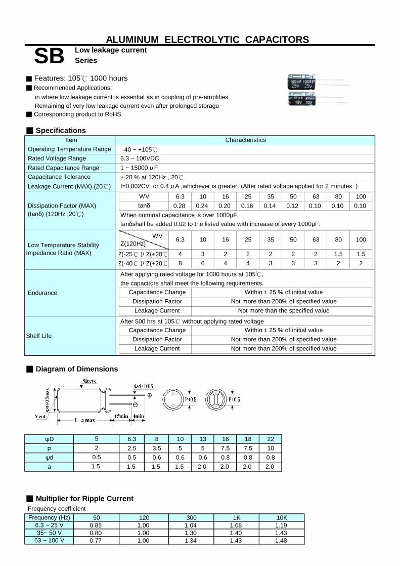
in where low leakage current is essential as in coupling of pre-amplifies
■ Corresponding product to RoHS
Rated Capacitance Range
6.3 10 16 25 35 50 63 80 1000.28 0.24 0.20 0.16 0.14 0.12 0.10 0.10 0.10
When nominal capacitance is over 1000μF,
4 3 2 2 2 2 2 1.5 1.58 6 4 4 3 3 3 2 2
the capacitors shall meet the following requirements.
■ Diagram of Dimensions
ψD 6.3 8 10 13 16 18 22P 2.5 3.5 5 5 7.5 7.5 10ψd 0.5 0.6 0.6 0.6 0.8 0.8 0.8a 1.5 1.5 1.5 2.0 2.0 2.0 2.0
■ Multiplier for Ripple Current
Frequency (Hz)6.3 ~ 25 V35~ 50 V
63 ~ 100 V
Within ± 25 % of initial value Not more than 200% of specified value
Not more than the specified value Dissipation Factor
Leakage Current Not more than 200% of specified value
Capacitance Change Within ± 25 % of initial value Dissipation Factor Not more than 200% of specified value
1 ~ 15000 μ F
Dissipation Factor (MAX) (tanδ) (120Hz ,20℃)
Leakage Current (MAX) (20℃) I=0.002CV or 0.4 μA ,whichever is greater. (After rated voltage applied for 2 minutes )
tanδ
tanδshall be added 0.02 to the listed value with increase of every 1000μF.
Frequency coefficient
Rated Voltage Range
Capacitance Tolerance
Shelf Life
52
1.5
Endurance
Remaining of very low leakage current even after prolonged storage
After applying rated voltage for 1000 hours at 105℃,
WVZ(120Hz) 6.3 10 16 100
Low Temperature StabilityImpedance Ratio (MAX)
63 80
Z(-25℃ )/ Z(+20℃)Z(-40℃ )/ Z(+20℃)
Low leakage current
■ Specifications
■ Features: 105℃ 1000 hours■ Recommended Applications:
ALUMINUM ELECTROLYTIC CAPACITORS
Operating Temperature Range -40 ~ +105℃
SB
Item
Series
Characteristics
6.3 ~ 100VDC
± 20 % at 120Hz , 20℃
WV
Capacitance Change
25
Leakage Current
After 500 hrs at 105℃ without applying rated voltage
35 50
0.5
0.85 1.04 1.08 1.1950 120 300
1.001.001.00
10K1K
1.34 1.43 1.481.30 1.40 1.430.80
0.77

1
2.2
3.3
4.7
10 5x11 40
22 5x11 50 5x11 55
33 5x11 55 5x11 60 5x11 70
47 5x11 65 5x11 75 5x11 85
100 5x11 95 5x11 110 6.3x11 140
220 6.3x11 165 6.3x11 180 8x11 230
330 6.3x11 195 8x11 250 8x11 280
470 8x11 270 8x11 300 10x12.5 400
1000 10x12.5 465 10x17 600 10x17 660
2200 13x20 925 13x20 1000 13x25 1210
3300 13x20 1100 13x25 1300 16x26 1610
4700 16x26 1600 16x26 1700 16x32 2020
6800 16x26 1810 16x32 2100 18x36 2520
10000 16x32 2210 18x36 2630 18x40 2910
15000 18x36 2760
☆ Size: Dψx L (mm) ☆ Ripple Current: (mA/rms). 105℃,120Hz
■Dimensions,Rated Ripple Current
16V ( 20 )Capacitance (μF)
Rated (Surge) Voltage
SIZE SIZE SIZERipple Ripple Ripple
10V ( 13 )
ALUMINUM ELECTROLYTIC CAPACITORS
SB Low leakage currentSeries
6.3V ( 8 )
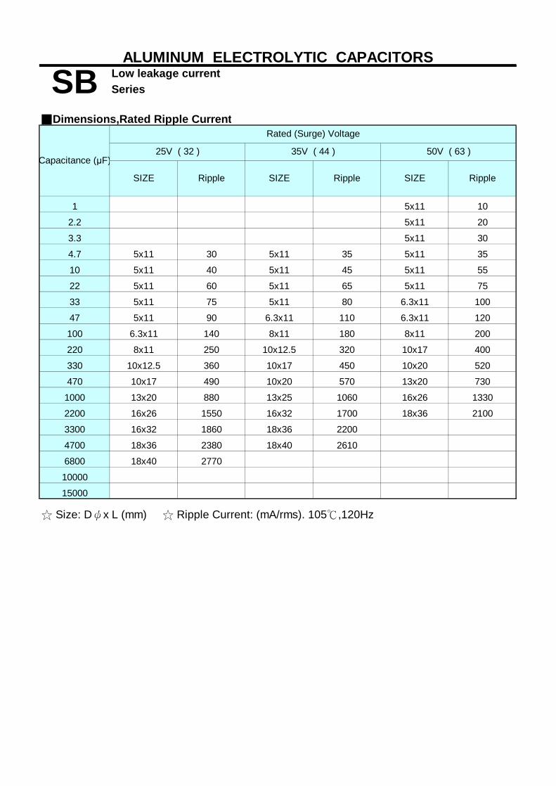
1 5x11 10
2.2 5x11 20
3.3 5x11 30
4.7 5x11 30 5x11 35 5x11 35
10 5x11 40 5x11 45 5x11 55
22 5x11 60 5x11 65 5x11 75
33 5x11 75 5x11 80 6.3x11 100
47 5x11 90 6.3x11 110 6.3x11 120
100 6.3x11 140 8x11 180 8x11 200
220 8x11 250 10x12.5 320 10x17 400
330 10x12.5 360 10x17 450 10x20 520
470 10x17 490 10x20 570 13x20 730
1000 13x20 880 13x25 1060 16x26 1330
2200 16x26 1550 16x32 1700 18x36 2100
3300 16x32 1860 18x36 2200
4700 18x36 2380 18x40 2610
6800 18x40 2770
10000
15000
☆ Size: Dψx L (mm) ☆ Ripple Current: (mA/rms). 105℃,120Hz
SB Low leakage currentSeries
ALUMINUM ELECTROLYTIC CAPACITORS
■Dimensions,Rated Ripple Current
SIZESIZE SIZERipple Ripple
Capacitance (μF)
Rated (Surge) Voltage
25V ( 32 ) 35V ( 44 ) 50V ( 63 )
Ripple

1 5x11 10
2.2 5x11 20
3.3 5x11 30
4.7 5x11 35 5x11 40
10 5x11 50 6.3x11 60 6.3x11 65
22 6.3x11 80 8x11 110 8x11 115
33 6.3x11 100 8x11 130 10x12.5 160
47 8x11 140 10x12.5 180 10x17 230
100 10x12.5 230 10x17 310 13x20 410
220 10x20 430 13x20 560 16x26 750
330 13x20 610 13x25 750 16x26 920
470 13x25 800 16x26 1020 16x32 1200
1000 16x32 1460 18x36 1830
2200
3300
4700
6800
10000
15000
☆ Size: Dψx L (mm) ☆ Ripple Current: (mA/rms). 105℃,120Hz
SIZESIZE SIZE RippleRippleRipple
ALUMINUM ELECTROLYTIC CAPACITORS
80V ( 100 ) 100V ( 125 )
SB Low leakage currentSeries
■Dimensions,Rated Ripple Current
Capacitance (μF)
Rated (Surge) Voltage
63V ( 79 )

■ Features: 105℃ 1000~3000 hours,Low impedance , high permissible ripple current SY at high frequency and high operation temperature (-40 ~ +105℃)■ Recommended Applications: Applicable for switching regulator of computer , SC
■Corresponding product to RoHS
Rated Capacitance Range
6.3 10 16 25 35 50 63 1000.22 0.19 0.16 0.14 0.12 0.10 0.09 0.08
tanδshall be added 0.02 to the listed value with increase of every 1000μF.
4 3 3 3 3 2 2 28 6 4 4 4 4 4 4
the capacitors shall meet the following requirements.
the capacitors shall meet the same requirement as Endurance.
ψD 5 8 10 13 16 18 22P 2.0 3.5 5.0 5.0 7.5 7.5 10.0ψd 0.50 0.6 0.6 0.6 0.8 0.8 0.8a 1.5 1.5 1.5 2.0 2.0 2.0 2.0
■ Multiplier for Ripple Current
Frequency (Hz)Below 4.7 μF5.6 ~ 33 μF34 ~ 330 μF
331 ~ 1000 μF1200 μF Above
16 35
If dimension is down size , Endurance will be less 1000 hours than standard
Z-25℃ / Z+20℃
25
Low Impedance and high frequency ALUMINUM ELECTROLYTIC CAPACITORS
SC Series
■ Specifications
6.3 ~ 100VDC4.7 ~ 15000 μF
Rated Voltage Range
Item Characteristics Operating Temperature Range -40 ~ +105℃
Endurance
Capacitance Tolerance ± 20 % at 120Hz , 20℃
Case Dia 5 x 11 ~ 10 x 12.5 10 x 15 higher
50 63
Not more than 200% of specified value
WV Leakage Current (MAX)(20℃) I=0.01CV or 3μA ,whichever is greater. (After rated voltage applied for 2 minutes )
Leakage Current
After applying rated voltage with ripple current for 3000 hours at 105℃,
Capacitance Change Dissipation Factor
tanδ Dissipation Factor (MAX) (tanδ) (120Hz ,20℃)
Not more than the specified value
When nominal capacitance is over 1000μF,
Impedance Ratio (MAX)
Low Temperature Stability
Z-40℃ / Z+20℃
100 WVZ(120Hz) 6.3 10
Frequency coefficient
1.5
Shelf Life
■ Diagram of Dimensions
0.5
6.32.5
Life
After placed at 105℃ without voltage applied for 1000 hours,
2000 3000
Within ± 20 % of initial value
* If dimension is down size,Endurance will be less 1000hrs than standard.
1K 10K 100K1.000.70 0.800.30
0.70 0.80
50 120 3000.40 0.50
0.40 0.50 0.60 0.80
0.65 0.90 0.90 0.98 1.00 1.000.90
0.90 1.001.00
Long Life
1.00
especially for high frequency
0.85 0.90 0.95 0.98 1.00
0.950.60
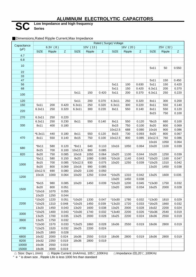
SIZE Ripple Z SIZE Ripple Z SIZE Ripple Z SIZE Ripple Z4.76.8
5x11 50 0.550223347 5x11 150 0.45056 5x11 100 0.630 5x11 150 0.42068 5x11 150 0.420 6.3x11 200 0.370
5x11 150 0.420 5x11 200 0.370 6.3x11 250 0.220
120 5x11 200 0.370 6.3x11 250 0.320 8x11 300 0.200150 5x11 200 0.420 6.3x11 250 0.320 6.3x11 300 0.220 8x11 550 0.140
6.3x11 250 0.320 6.3x11 300 0.220 8x11 550 0.140 8x11 550 0.1208x15 750 0.100
270 6.3x11 250 0.2206.3x11 250 0.230 8x11 550 0.140 8x11 550 0.120 *8x15 660 0.1008x11 400 0.180 8x15 750 0.100 8x20 800 0.069
10x12.5 688 0.080 10x16 900 0.086*6.3x11 440 0.180 8x11 550 0.120 8x15 730 0.093 8x20 800 0.067
8x11 550 0.140 8x15 750 0.100 10x12.5 800 0.085 10x12.5 760 0.08610x16 1050 0.064
*8x11 580 0.120 *8x11 640 0.110 10x16 1050 0.064 10x20 1100 0.0398x15 700 0.100 10x12.5 800 0.085
820 8x20 750 0.085 10x16 1050 0.064 10x20 1100 0.044 10x20 1250 0.039*8x11 580 0.150 8x20 1080 0.065 *10x16 1140 0.043 *10x20 1160 0.0478x15 700 0.085 *10x12.5 930 0.075 10x20 1250 0.039 *10x25 1310 0.0428x20 800 0.069 10x16 990 0.085 13x20 1450 0.038
10x12.5 690 0.080 10x20 1100 0.05010x16 1000 0.064 10x20 1250 0.044 *10x25 1310 0.042 13x25 1600 0.035
13x20 1450 0.038*8x15 980 0.085 10x20 1450 0.039 *10x20 1200 0.045 *13x30 1750 0.0328x20 800 0.051 13x20 1600 0.034 16x25 2000 0.028
*10x16 1070 0.05510x20 1250 0.044*10x20 1220 0.051 *10x20 1330 0.047 *10x30 1780 0.032 *13x30 1810 0.029*10x25 1310 0.048 *10x25 1450 0.039 *13x20 1720 0.033 *16x25 1660 0.03213x20 1450 0.043 13x20 1600 0.038 13x25 2000 0.028 16x32 2200 0.024*10x25 1400 0.043 *10x30 1740 0.032 *13x40 2200 0.026 *16x36 2540 0.01913x25 1700 0.035 13x25 2000 0.028 16x25 2200 0.024 18x36 2550 0.019
3900 13x25 1750 0.032*13x30 1570 0.033 *13x25 1860 0.028 16x36 2550 0.019 18x36 2800 0.019*13x25 1520 0.032 16x25 2200 0.02416x25 1800 0.028
6800 16x32 2000 0.024 16x36 2550 0.019 18x36 2800 0.019 18x36 2800 0.0198200 16x32 2350 0.019 18x36 2800 0.01910000 16x36 2550 0.01915000 18x36 3000 0.019
680
1200
■Dimensions,Rated Ripple Current,Max Impedance
10V ( 13 )6.3V ( 8 ) 16V ( 20 )
3300
☆ Size: Dψx L (mm) ☆ Ripple Current: (mA/rms), 105℃,100KHz ☆Impedance (Ω),20℃,100KHz
4700
25V ( 32 )
10
100
220
470
1500
1000
ALUMINUM ELECTROLYTIC CAPACITORS
SC Low Impedance and high frequencySeries
" * " is down size , Ripple Life is less 1000 hrs than standard
Rated ( Surge) Voltage Capacitance
(μF)
330
2200

SIZE Ripple Z SIZE Ripple Z SIZE Ripple Z SIZE Ripple Z4.7 5x11 115 1.200 5x11 115 2.000 5x11 115 2.200 5x11 120 2.0006.8 5x11 120 1.000 5x11 120 1.850 5x11 120 2.000 5x11 140 1.85010 5x11 140 0.900 5x11 140 1.700 5x11 140 1.850 6.3x11 200 1.50015 5x11 170 0.690 5x11 180 1.200 5x11 200 1.700 6.3x11 250 1.20022 5x11 190 0.600 5x11 200 0.700 6.3x11 250 1.200 8x11 300 0.79033 5x11 200 0.580 6.3x11 250 0.600 6.3x11 300 0.900 8x15 450 0.59047 6.3x11 250 0.390 6.3x11 300 0.520 8x11 450 0.700 10x16 550 0.35068 6.3x11 300 0.220 8x11 450 0.350 8x11 550 0.520 10x20 650 0.240
6.3x11 300 0.180 8x11 450 0.290 8x20 650 0.350 13x20 800 0.1808x11 450 0.140 8x15 550 0.250
120 8x11 550 0.130 8x20 650 0.210 10x16 800 0.300 13x25 1050 0.150150 8x15 650 0.100 10x12.5 800 0.160 10x16 1050 0.200 13x25 1300 0.110
8x15 650 0.100 *10x16 1050 0.100 10x20 1300 0.150 16x25 1400 0.07110x12.5 800 0.069 10x25 1050 0.068*10x16 900 0.052 10x20 1300 0.072 13x20 1400 0.100 16x32 1550 0.04910x20 1050 0.04410x20 1300 0.039 *10x20 1390 0.075 13x25 1550 0.064 18x36 1770 0.038
13x20 1400 0.060680 13x20 1400 0.038 13x25 1550 0.050 16x25 1700 0.052820 13x20 1550 0.034 16x25 1700 0.040 16x32 1900 0.048
1000 13x25 1700 0.029 16x25 1900 0.039 16x32 2100 0.0421200 16x25 1900 0.028 16x32 2100 0.025 16x36 2550 0.0361500 16x25 2100 0.024 16x36 2550 0.025 18x36 2800 0.033
*16x32 2300 0.021 18x40 2800 0.02516x36 2550 0.019
3300 18x36 2880 0.01939004700680082001000015000
" * " is down size , Ripple Life is less 1000 hrs than standard
100V ( 125 )Capacitance(μF)
RATED ( SURAGE ) VOLTAGE
☆ Size: Dψx L (mm) ☆ Ripple Current: (mA/rms), 105℃,100KHz ☆Impedance (Ω),20℃,100KHz
470
2200
50V ( 63 ) 63V ( 79 )
330
100
220
35V ( 44 )
ALUMINUM ELECTROLYTIC CAPACITORS
SC Low Impedance and high frequencySeries
■Dimensions,Rated Ripple Current,Max Impedance
Series Rated Voltage Capacitan Rated Code for Lead Wire Check or
Series Rated Voltage Capacitan Rated Code for Lead Wire Check orSeries Rated Voltage Capacitan Rated Code for Lead Wire Check or

SJ■ Recommended Applications : AV(TV, Video, Audio), Monitor/Computer,
SC■Corresponding product to RoHS
Rated Capacitance Range
I= Leakage Current (μA) C= Nominal Capacitance (μF) V= Rated Voltage (V)
6.3 10 16 25 35 1000.22 0.19 0.16 0.14 0.12 0.08
tanδ shall be added 0.02 to the listed value with increase of every 1000μF.
2 2 2 2 2 23 3 3 3 3 3
After applying rated voltage with max ripple current for 1000~5000
the capacitor shall meet the same requirement as Endurance.
■ Dimensions [mm]
ψD 4 10 13P 1.5 5.0 5.0ψd 0.45 0.6 0.6a 1.0 1.5 2.0
■ Multiplier for Ripple CurrentFrequency coefficient
5.6 ~ 390470 ~ 10001200 ~ 6800
Low Impedance and High ripple
I≦0.01CV or 3μA ,whichever is greater. (After rated voltage applied for 2 minutes)
ALUMINUM ELECTROLYTIC CAPACITORS
Operating Temperature Range -40 ~ +105℃
± 20 % at 120Hz
Dissipation Factor (MAX) (tanδ) (120Hz ,20℃)
Leakage Current (MAX) (20℃)
SJ
Life time (hrs)
1000
35
5000
Item
Series
Characteristics■ Specifications
OA/HA/Communication,Converter/Inverter,Adapter, SMPS
■ Features: 105℃, 1000〜5000hrs Low Impedance and High ripple High ripple
6.3 ~ 100VDC Rated Voltage Range (WV)
When nominal capacitance is over 1000μF,
Endurance
5.6 ~ 6800 μF Capacitance Tolerance (20℃)
*If dimension is down size,Endurance will be less 1000 hours than standard.
hours at 105℃, the capacitor shall meet the following requirement.
10 16 25
2
Leakage Current ψD = 1030004000
Dissipation Factor
WVtanδ
WV Z(120Hz)
630.09
50 63
500.10
6.3
2
100
3
ψD≦6.3ψD = 8
L≧11
L=7Case (ψ)
ψD≧13
0.87.5 7.50.8
Low Temperature Stability Impedance Ratio (Max)
1816
3Z(-25℃) / Z(20℃)Z(-40℃) / Z(20℃)
2.02.0
0.850.90
10K
1.001.00
100K
0.650.75
0.750.950.98
0.70
After placed at 105℃without voltage applied for 1000 hours (500 hours for L=7),
2000
3.5
1.001.000.950.80
1K
0.60
Within±25% of the initial value
Not more than the specified value
Not more than 200% of the specified value
0.6 ( 0.5 )
Capacitance Change
Freq. (Hz)Cap (μF) 50 120
1.5 ( 1.0 )
Shelf Life
1.5 ( 1.0 )
52
0.5 ( 0.45 )1.5 ( 1.0 )
6.32.5
0.5 ( 0.45 )
8
( ) : L = 7

SIZE Ripple Z SIZE Ripple Z SIZE Ripple Z SIZE Ripple Z SIZE Ripple Z
10 4x7 130 0.96
15 4x7 130 0.94 5x7 190 0.57
18 4x7 130 0.92 5x7 170 0.69 5x7 210 0.47
27 4x7 130 0.89 5x7 190 0.61 5x7 210 0.46 5x11 230 0.37
33 5x7 160 0.75 5x7 210 0.45 5x11 220 0.42 5x11 250 0.30
39 4x7 130 0.85 5x7 175 0.64 5x11 220 0.43 5x11 230 0.36 6.3x7 300 0.25
6.3x11 380 0.15
8x7 350 0.19
6.3x11 410 0.13
8x7 380 0.16
6.3x11 340 0.19
8x7 310 0.22
5x11 200 0.43 6.3x11 370 0.16 6.3x11 410 0.13
6.3x7 240 0.35 8x7 350 0.18 8x7 380 0.15
5x11 220 0.38 6.3x11 410 0.13
6.3x7 270 0.29 8x7 380 0.15
5x11 250 0.3
6.3x7 300 0.23
8x15 910 0.068
10x12.5 930 0.065
8x15 900 0.068
10x12.5 930 0.065
8x15 1000 0.056 8x20 1250 0.041
10x12.5 1030 0.053 10x16 1430 0.038
8x15 910 0.068 8x20 1140 0.049
10x12.5 940 0.064 10x16 1300 0.046
8x20 1250 0.041
10x16 1430 0.038
8x20 1130 0.05
10x16 1300 0.046
8x20 1250 0.041
10x16 1430 0.038
8x20 1250 0.041 13x30 3290 0.016
10x16 1430 0.038 16x20 3140 0.018
1500 10x20 1820 0.026 10x25 2150 0.023 13x20 2360 0.021 13x25 2770 0.018 13x35 3400 0.015
13x30 3290 0.016
16x20 3140 0.018
2200 10x25 2150 0.023 13x20 2360 0.021 13x25 2770 0.018 13x35 3400 0.015
13x30 3290 0.016
16x20 3140 0.018
3300 13x20 2360 0.021 13x25 2770 0.018 13x35 3400 0.015
13x30 3290 0.016
16x20 3140 0.018
4700 13x30 3290 0.016 13x35 3400 0.015
13x35 3400 0.015
16x20 3140 0.018
6800 16x25 3460 0.016
10x12.5 1030 0.053
10x12.5 1030 0.053
10x12.5
620 0.1 8x11
380
■Dimensions, Rated Ripple Current,Max Impedance
ALUMINUM ELECTROLYTIC CAPACITORS
SJ Low Impedance and High rippleSeries
0.072
120 6.3x7 300
0.088
0.23
8x7 340 0.18 8x7
35V (44)
☆ Size: Dψx L (mm) ☆ Ripple Current : mA/rms,105℃,100KHz ☆Impedance : Z(Ω),20℃,100KHz
150
180
220
0.105 8x11 760
47 5x7 175 0.7
Rated ( Surage ) Voltage Capacitance
(μF) 10V ( 13 )6.3V ( 8 ) 16V (20) 25V (32)
230 0.36 5x11 2505x7 190 0.53 5x11
300 0.24
0.3
56 5x7 190 0. 56 5x7 210 0.44
68 5x7 210 0.43
0.3 6.3x75x11 250
300 0.24 8x11 5105x11 210 0.44 6.3x7
0.12 8x11
0.12
100 5x11 250 0.3 8x11 620 0.105
8x7 350 0.18 8x11 510 0.12
0.15 8x11 560 0.11
680 0.088
8x11 630
8x11 560
8x11 690 0.088
8x7 380 0.15 6.3x11 410 0.13 8x11
1250 0.041
760 0.072
270 6.3x11 370 0.16 8x11 580
330 6.3x11 410 0.13
690 8x200.12 8x11
760 0.072 10x161030 0.0538x11 640 0.1 8x11 1430 0.038
470 8x11 680 0.086 8x11 760 0.072 10x20 1820 0.026
560 8x11 760 0.072 10x20 1650 0.032 10x25
0.032 10x25
2150 0.023
680 8x15 900 0.062 10x20 1820
820 8x15 1000 0.056 10x20 1650 2150 0.023 13x25 2510
2360 0.0230.026 13x20
2770 0.018
0.02
1000 10x12.5 1030 0.053 10x20 1820 0.026
1200 10x20 1820 0.026
0.021 13x2513x20 2360
0.022 13x25
10x25 2150 0.023 13x25
1800 10x25 1940 0.025 13x20 2230 2510 0.02 16x25 3460
2510 0.02
0.016
2700 13x20 2230 0.022 13x25 2510 0.02
3900 13x25 2770 0.018
0.01616x25 3460
16x25 3460 0.016
5600 16x25 3460 0.016
70
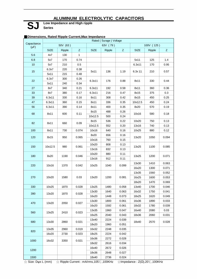
SIZE Ripple Z SIZE Ripple Z SIZE Ripple Z
5.6 4x7 130 1
6.8 5x7 170 0.74 5x11 125 1.4
10 5x7 210 0.5 6.3x11 170 0.95
6.3x7 220 0.38
5x11 215 0.48
6.3x7 300 0.26
5x11 240 0.34
27 8x7 340 0.21 6.3x11 192 0.58 8x11 360 0.36
33 8x7 380 0.17 6.3x11 216 0.47 8x15 375 0.3
39 6.3x11 330 0.16 8x11 308 0.42 8x15 450 0.25
47 6.3x11 360 0.15 8x11 336 0.35 10x12.5 450 0.24
56 6.3x11 390 0.14 8x11 400 0.35 8x20 570 0.19
8x15 488 0.26
10x12.5 500 0.24
8x15 536 0.22 10x20 750 0.13
10x12.5 552 0.20 13x16 740 0.13
100 8x11 730 0.074 10x16 640 0.16 10x25 880 0.12
8x20 656 0.16
10x16 760 0.15
10x20 808 0.13
13x16 832 0.13
10x20 880 0.11
13x16 912 0.11
13x30 1410 0.063
16x20 1300 0.071
13x35 1560 0.052
16x25 1600 0.053
18x20 1470 0.069
330 10x25 1870 0.028 13x25 1480 0.058 13x40 1700 0.046
13x30 1640 0.063 16x32 1750 0.041
16x20 1448 0.073 18x25 1620 0.049
13x30 1800 0.061 16x36 1890 0.033
16x20 1592 0.061 18x32 1780 0.039
13x35 1960 0.047 16x40 2080 0.03
16x25 2040 0.043 18x36 2060 0.031
13x40 2224 0.039
18x20 1960 0.051
13x35 2960 0.019 16x32 2248 0.035
16x20 2730 0.023 18x25 2224 0.042
16x36 2272 0.028
18x32 2616 0.034
16x40 2672 0.026
18x36 2648 0.027
1500 18x40 2736 0.024
ALUMINUM ELECTROLYTIC CAPACITORS
■Dimensions, Rated Ripple Current,Max Impedance
Capacitance(μF)
Rated ( Surage ) Voltage
SJ Low Impedance and High rippleSeries
68
63V ( 79 ) 100V ( 125 )50V (63 )
5x11 136 1.19 6.3x 1115 210 0.57
22 6.3x11 176 0.88 8x11 330 0.44
580 0.18
82 8x11 660 0.09
8x11 600 0.11 10x16
1100 0.085
120 8x15 950 0.065
1190 0.046
13x20 1050 0.094
150 10x12.5 980 0.061 13x25
0.071
10x25 1040 0.099220 10x16 1370 0.042
180 8x20
0.028
0.03
13x25 1200
13x20 1200 0.081270 10x20 1580
470 13x20 2050
390 13x20 1870
0.027
0.021
560 13x25 2410 0.023
18x40 2570 0.028
820
680 13x30 2860
1000 16x32 3350 0.021
☆ Size: Dψx L (mm) ☆ Ripple Current : mA/rms,105℃,100KHz ☆Impedance : Z(Ω),20℃,100KHz
1200

■ Features:105℃ 5000~6000hrs Low Impedance and long Life TB■ Recommended Applications : AV(TV, Video, Audio), Monitor/Computer, Long Life
SJ
■ Specifications
-40 ~ +105℃6.3~35VDC
Rated Capacitance Range 27~ 8200μF Capacitance Tolerance ± 20 % at 120Hz , 20℃
I=0.01CV or 3(μA) , whichever is greater. (After rated voltage applied for 2 minutes )
I= Leakage Current (μA) C= Nominal Capacitance (μF) V= Rated Voltage (V) (20℃)
6.3 10 16 25 350.22 0.19 0.16 0.14 0.12
When nominal capacitance is over 1000uF,Tanδ shall be added 0.02 to the listed value with increase of every 1000uF.
2 2 2 2 23 3 3 3 3
After applying rated voltage with rated ripple current for 5000~6000hours at 105℃,
Capacitance ChangeDissipation FactorLeakage Current
After placed at 105℃without voltage applied for 500 hours,
■ Diagram of Dimensions
5 6.3 8 10 13 162.0 2.5 3.5 5.0 5.0 7.50.5 0.5 0.6 0.6 0.6 0.81.5 1.5 1.5 1.5 2.0 2.0
■ Multiplier for Ripple CurrentFrequency coefficient
10
the capacitors shall meet the following requirements.
Dφ
35
φ5~6.3φ
Z-25℃ / Z+20℃
6.3
WV
27 to 150
Freq. (Hz)Cap(μF) 120
0.40
ψDPψda
Shelf Life
Endurance
5000hrsφ8~16φ
Low Temperature StabilityImpedance Ratio (MAX)
16 25
Within ± 25 % of initial value(6.3, 10Vdc :±30%)200% or less of initial specified value
WVZ(120Hz)
4700 to 8200
2200 to 39000.850.75
220 to 560680 to 1800
0.500.60
ALUMINUM ELECTROLYTIC CAPACITORS
Dissipation Factor (MAX) (tanδ) (120Hz ,20℃)
Characteristics Operating Temperature Range
TB
Item
Rated Voltage Range
Leakage Current (MAX) (20℃)
■Corresponding product to RoHS
Life
0.90
the capacitors shall meet the same requirement as Endurance.
1.000.750.85
0.900.940.95
1.00
1.001.001.00
6000hrs
0.87
0.980.95
0.95
Low Impedance and Long LifeSeries
OA/HA/Communication,Converter/Inverter,Adapter, SMPS
100K1K 10K
initial specified value or less
Z-40℃ / Z+20℃
tanδ

SIZE Ripple Z SIZE Ripple Z SIZE Ripple Z SIZE Ripple Z SIZE Ripple Z2747 5x11 330 0.245668 5x11 330 0.24
100 5x11 330 0.24 6.3x11 500 0.11120150 5x11 330 0.24 6.3x11 500 0.11220 5x11 330 0.24 6.3x11 500 0.11 8x12 900 0.062270 8x15 1210 0.048330 6.3x11 500 0.11 8x12 900 0.062 10x12.5 1240 0.053390 8x15 1210 0.048 8x20 1410 0.041470 6.3x11 500 0.11 8x12 900 0.062 10x12.5 1240 0.053 10x16 1650 0.038560 8x20 1410 0.041 10x20 1960 0.026
8x12 900 0.062 8x15 1210 0.048 10x16 1650 0.038 10x25 2250 0.02310X12.5 1240 0.053
820 8x12 900 0.062 10x20 1960 0.0268x15 1210 0.048 8x20 1410 0.041 10x25 2250 0.023 13x20 2480 0.023
10x12.5 1240 0.053 10X16 1650 0.0388x15 1210 0.048 13x25 2900 0.020
10X12.5 1240 0.0538x20 1410 0.041 8x20 1410 0.041 10x20 1960 0.026 13x20 2480 0.023 13x30 3450 0.017
10x16 1650 0.038 16x20 3250 0.0181800 10x16 1650 0.038 10x20 1960 0.026 10x25 2250 0.023 13x25 2900 0.020 13x35 3570 0.016
10x20 1960 0.026 10x25 2250 0.023 13x20 2480 0.023 13x30 3450 0.017 16x25 3630 0.01716x20 3250 0.018
2700 10x25 2250 0.023 13x25 2900 0.020 13x35 3570 0.01613x20 2480 0.023 13x30 3450 0.017 16x25 3630 0.017
16x20 3250 0.0183900 13x20 2480 0.023 13x25 2900 0.020 13x35 3570 0.016
13x25 2900 0.020 13x30 3450 0.017 16x25 3630 0.01716x20 3250 0.018
5600 13x30 3450 0.017 13x35 3570 0.01613x35 3570 0.016 16x25 3630 0.01716x20 3250 0.018
8200 16x25 3630 0.017
1500
2200
6.3V ( 8 ) 10V ( 13 ) 35V ( 44 )25V ( 32 ) 16V ( 20 )
1000
6800
☆ Size: Dψx L (mm) ☆ Ripple Current: (mA/rms), 105℃,100KHz ☆Impedance (Ω),20℃,100KHz
1200
4700
3300
680
ALUMINUM ELECTROLYTIC CAPACITORS
TB Low Impedance & Long LifeSeries
■Dimensions,Rated Ripple Current,Max Impedance
Capacitance (μF)
Rated ( Surge) Voltage
Series Rated Voltage Capacita Rated Code for Lead Wire Check Series Rated Voltage Capacita Rated Code for Lead Wire Check Series Rated Voltage Capacita Rated Code for Lead Wire Check Lead Wire Check Lead Wire Check Lead Wire Check Lead Wire Check Lead Wire Check Lead Wire Check

■ Features : Low Impedance , high permissible ripple current at high frequency SY and long life than SC■ Recommended Applications: SC Used switching requlator applications in computers. Especially for high frequency.■ Corresponding product to RoHS
Rated Capacitance Range
I= Leakage Current (μA) C= Nominal Capacitance (μF) V= Rated Voltage (V)6.3 10 16 25 35 50 63 100
0.22 0.19 0.16 0.14 0.12 0.10 0.09 0.08
4 3 2 2 2 2 2 28 6 4 3 3 3 3 3
DψLife
ψD 5 8P 2.0 3.5ψd 0.5 0.6a 1.5 1.5
■ Multiplier for Ripple Current
WVtanδ
0.850.87
Z-25℃ / Z+20℃Z-40℃ / Z+20℃
6.3
1 K0.75
0.5
10063
Endurance
5000 hrs3000 hrs
Dissipation Factor Not more than 200% of specified value Not more than the specified value
5ψ~6.3ψ 8ψ~10ψx12.5
Rated Voltage Range
Item
Dissipation Factor (MAX) (tanδ) (120Hz ,20℃) When nominal capacitance is over 1000μF,
10
4000 hrs13ψ~18ψ
the capacitors shall meet the following requirements.
Low Temperature StabilityImpedance Ratio (MAX)
WVZ(120Hz)
tanδshall be added 0.02 to the listed value with increase of every 1000μF.
5016 25 35
I=0.01CV or 3μA ,whichever is greater. (After rated voltage applied for 2 minutes)±20% at 120Hz , 20℃
-40 ~ +105℃6.3 ~ 100VDC
*If dimension is down size,Endurance will be less 1000 hours than standard.6000 hrs
Leakage Current
After applying rated voltage with rated ripple current for 6000 hours at 105℃,
Capacitance Change Within ± 25% of initial value
10ψx15~12ψ
Low Impedance & Long LifeALUMINUM ELECTROLYTIC CAPACITORS
SY Series
Leakage Current (MAX) (20℃)
Capacitance Tolerance
■ Specifications
2.2 ~ 15000 μF
Characteristics Operating Temperature Range
10
2.0
0.400.500.60
0.8 0.82.0
0.62.01.5
Frequency coefficient
the capacitors shall meet the same requirement as Endurance.
■ Diagram of Dimensions
185.0 7.5 7.55.02.513 166.3
0.61.5
1.001.00
10 K0.900.940.95
100 K1.001.001.00
4700 μF Higher 0.950.98
0.750.85
0.900.95
Shelf Life
120
Long Life
2200 ~ 3900 μF
Frequency (Hz)
220 ~ 560 μF22 ~ 180 μF
680 ~1800 μF
After placed at 105℃ without voltage applied for 1000 hours,
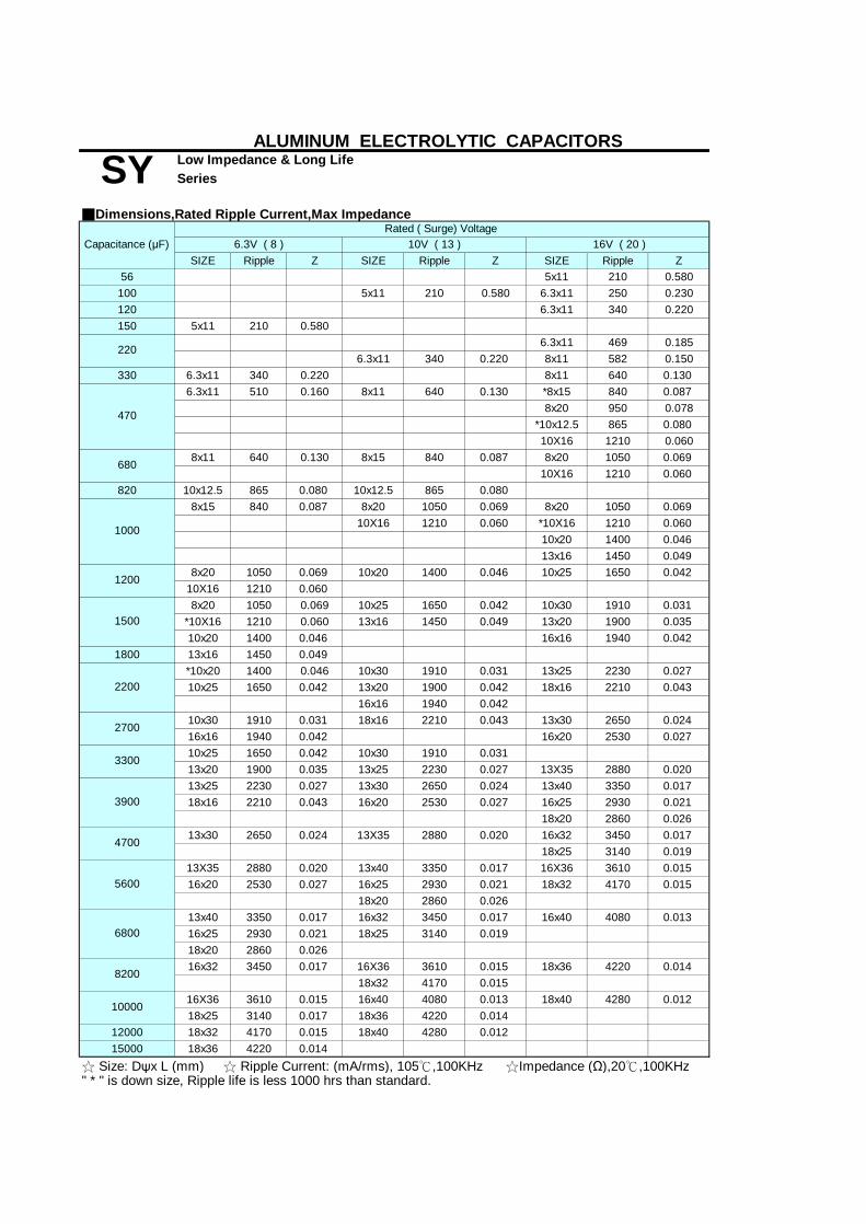
SIZE Ripple Z SIZE Ripple Z SIZE Ripple Z56 5x11 210 0.580
100 5x11 210 0.580 6.3x11 250 0.230120 6.3x11 340 0.220150 5x11 210 0.580
6.3x11 469 0.1856.3x11 340 0.220 8x11 582 0.150
330 6.3x11 340 0.220 8x11 640 0.1306.3x11 510 0.160 8x11 640 0.130 *8x15 840 0.087
8x20 950 0.078*10x12.5 865 0.08010X16 1210 0.060
8x11 640 0.130 8x15 840 0.087 8x20 1050 0.06910X16 1210 0.060
820 10x12.5 865 0.080 10x12.5 865 0.0808x15 840 0.087 8x20 1050 0.069 8x20 1050 0.069
10X16 1210 0.060 *10X16 1210 0.06010x20 1400 0.04613x16 1450 0.049
8x20 1050 0.069 10x20 1400 0.046 10x25 1650 0.04210X16 1210 0.0608x20 1050 0.069 10x25 1650 0.042 10x30 1910 0.031
*10X16 1210 0.060 13x16 1450 0.049 13x20 1900 0.03510x20 1400 0.046 16x16 1940 0.042
1800 13x16 1450 0.049*10x20 1400 0.046 10x30 1910 0.031 13x25 2230 0.02710x25 1650 0.042 13x20 1900 0.042 18x16 2210 0.043
16x16 1940 0.04210x30 1910 0.031 18x16 2210 0.043 13x30 2650 0.02416x16 1940 0.042 16x20 2530 0.02710x25 1650 0.042 10x30 1910 0.03113x20 1900 0.035 13x25 2230 0.027 13X35 2880 0.02013x25 2230 0.027 13x30 2650 0.024 13x40 3350 0.01718x16 2210 0.043 16x20 2530 0.027 16x25 2930 0.021
18x20 2860 0.02613x30 2650 0.024 13X35 2880 0.020 16x32 3450 0.017
18x25 3140 0.01913X35 2880 0.020 13x40 3350 0.017 16X36 3610 0.01516x20 2530 0.027 16x25 2930 0.021 18x32 4170 0.015
18x20 2860 0.02613x40 3350 0.017 16x32 3450 0.017 16x40 4080 0.01316x25 2930 0.021 18x25 3140 0.01918x20 2860 0.02616x32 3450 0.017 16X36 3610 0.015 18x36 4220 0.014
18x32 4170 0.01516X36 3610 0.015 16x40 4080 0.013 18x40 4280 0.01218x25 3140 0.017 18x36 4220 0.014
12000 18x32 4170 0.015 18x40 4280 0.01215000 18x36 4220 0.014
10000
☆ Size: Dψx L (mm) ☆ Ripple Current: (mA/rms), 105℃,100KHz ☆Impedance (Ω),20℃,100KHz
1200
680
ALUMINUM ELECTROLYTIC CAPACITORS
SY Low Impedance & Long LifeSeries
" * " is down size, Ripple life is less 1000 hrs than standard.
470
1000
3300
6800
8200
■Dimensions,Rated Ripple Current,Max Impedance
Capacitance (μF)Rated ( Surge) Voltage
6.3V ( 8 ) 10V ( 13 ) 16V ( 20 )
4700
5600
220
1500
2200
2700
3900
Series Rated Voltage Capacitanc Rated Code for Standard Lead Wire Check orSeries Rated Voltage Capacitanc Rated Code for Standard Lead Wire Check orSeries Rated Voltage Capacitanc Rated Code for Standard Lead Wire Check or

SIZE Ripple Z SIZE Ripple Z SIZE Ripple Z2.2 5x11 85 2.2804.7 5x11 95 2.400 5x11 100 2.00010 5x11 130 1.600 5x11 135 1.20022 5x11 180 0.70033 5x11 210 0.580 6.3x11 245 0.49047 5x11 210 0.580 6.3x11 275 0.390 6.3x11 300 0.52056 6.3x11 340 0.220 6.3x11 295 0.30068 6.3x11 500 0.17082 6.3x11 540 0.160
100 6.3x11 340 0.220 8x11 580 0.150 8x11 555 0.170120 8x15 730 0.120150 8x11 640 0.160 8x11 640 0.130 10x12.5 760 0.120180 8x20 910 0.091
8x11 640 0.130 *8x15 840 0.087 10X16 1050 0.08410x12.5 865 0.080
8x20 1050 0.069 10x20 1220 0.06013x16 1260 0.061
8x15 840 0.087 *10X16 1210 0.060 *10x20 1400 0.05810x12.5 865 0.080 10x20 1400 0.046 10x25 1440 0.055
8x20 1050 0.069 10x20 1400 0.046 10x30 1690 0.043*10x12.5 1050 0.070 13x16 1450 0.049 13x20 1660 0.04510X16 1210 0.060 16x16 1690 0.055
10x25 1650 0.042 13x25 1950 0.03418x16 1930 0.054
10x20 1400 0.046 10x30 1910 0.031 13x30 2310 0.03013x16 1450 0.049 13x20 1900 0.035
16x16 1940 0.04210x25 1650 0.042 13x20 1900 0.035 13X35 2510 0.025
16x20 2210 0.03413x25 2230 0.027 13x40 2920 0.021
10x30 1910 0.031 18x16 2210 0.043 16x25 2555 0.02513x20 1900 0.035 18x20 2490 0.03616x16 1940 0.04218x16 2210 0.043 13x30 2650 0.024 16x32 3010 0.022
16x20 2530 0.027 18x25 2740 0.026*13x20 1900 0.035 13X35 2880 0.020 16X36 3150 0.01913x25 2230 0.02713x30 2650 0.024 13x40 3350 0.017 16x40 3710 0.01616x20 2530 0.027 16x25 2930 0.021 18x32 3635 0.021
18x20 2860 0.02613X35 2880 0.020 16x32 3450 0.017 18x36 3680 0.01718x20 2860 0.026 18x25 3140 0.01913x40 3350 0.017 16X36 3610 0.015 18x40 3800 0.01416x25 2930 0.021 18x32 4170 0.01516x32 3450 0.017 16x40 4080 0.01318x25 3140 0.019 18x36 4220 0.014
3900 18x32 4170 0.015 18x40 4280 0.0124700 18x36 4220 0.0145600 18x40 4280 0.012
" * " is down size, Ripple life is less 1000 hrs than standard.
1000
1500
330
2200
2700
3300
☆ Size: Dψx L (mm) ☆ Ripple Current: (mA/rms), 105℃,100KHz ☆Impedance (Ω),20℃,100KHz
1800
50V ( 63 )
270
470
560
1200
680
820
ALUMINUM ELECTROLYTIC CAPACITORS
SY Low Impedance & Long LifeSeries
220
■Dimensions,Rated Ripple Current,Max Impedance
Capacitance (μF)Rated ( Surge) Voltage
25V ( 32) 35V ( 44 )
Series Rated Voltage Capacitance Rated Code for Standard Lead Wire Check orSeries Rated Voltage Capacitance Rated Code for Standard Lead Wire Check orSeries Rated Voltage Capacitance Rated Code for Standard Lead Wire Check or
Series Rated Voltage Capacitance Rated Code for Standard Lead Wire Check orSeries Rated Voltage Capacitance Rated Code for Standard Lead Wire Check or

SIZE Ripple Z SIZE Ripple Z6.8 5×11 55 2.315 5×11 55 2.3 6.3×11 115 1.227 8×12 232 0.6333 6.3×11 115 1.239 8×15 300 0.4547 10×12.5 288 0.4356 8×12 232 0.63 8×20 362 0.3368 10×16 357 0.31
8×15 300 0.45 10×20 466 0.2110×12.5 288 0.43 13×16 466 0.23
100 10×25 531 0.28×20 362 0.33 10×30 663 0.15
10×16 357 0.31 13×20 690 0.16150 16×16 795 0.14
10×20 466 0.21 13×25 784 0.1213×16 466 0.23 18×16 920 0.1210×25 531 0.2 13×30 905 0.1
16×20 1040 0.09110×30 663 0.1513×20 690 0.16 13X35 1050 0.08316×16 795 0.14 16×25 1250 0.07313×25 784 0.12 13×40 1180 0.071
18×20 1240 0.0816×32 1570 0.054
18×16 920 0.12 18×25 1490 0.05713×30 905 0.1 16×36 1790 0.04516×20 1040 0.091 18×32 1630 0.04713X35 1050 0.08316×25 1250 0.073 16×40 2020 0.0413×40 1180 0.07118×20 1240 0.08 18×36 1790 0.0416×32 1570 0.05418×25 1490 0.057 18×40 2330 0.03616×36 1790 0.04518×32 1630 0.047
1200 16×40 2020 0.04
☆ Size: Dψx L (mm) ☆ Ripple Current: (mA/rms), 105℃,100KHz ☆Impedance (Ω),20℃,100KHz
560
680
820
1000
180
220
270
330
390
470
ALUMINUM ELECTROLYTIC CAPACITORS
SY Low Impedance & Long LifeSeries
82
120
■Dimensions,Rated Ripple Current,Max Impedance
Capacitance (μF)Rated ( Surge) Voltage
63V ( 79) 100V (125 )

Low Impedance & Long Life Series
■ Features:105℃ 4000~10000hrs Low Impedance and long Life TA■ Recommended Applications: Long Life Applicable for SMPS, Adaptor,Charger,Monitor/Computer SY
■ Specifications
-40 ~ +105℃6.3~35VDC
Rated Capacitance Range 33 ~ 8200μF Capacitance Tolerance ± 20 % at 120Hz , 20℃
I=0.01CV or 3(μA) , whichever is greater. (After rated voltage applied for 2 minutes )
I= Leakage Current (μA) C= Nominal Capacitance (μF) V= Rated Voltage (V) (20℃)
6.3 10 16 25 350.22 0.19 0.16 0.14 0.12
When nominal capacitance is over 1000uF,Tanδ shall be added 0.02 to the listed value with increase of every 1000uF.
4 3 2 2 28 6 4 3 3
After applying rated voltage with rated ripple current for 4000~10000hours at 105℃,
Capacitance ChangeDissipation FactorLeakage Current
After placed at 105℃without voltage applied for 1000 hours,
■ Diagram of Dimensions
5 6.3 8 10 13 16 182.0 2.5 3.5 5.0 5.0 7.5 7.50.5 0.5 0.6 0.6 0.6 0.8 0.81.5 1.5 1.5 1.5 2.0 2.0 2.0
■ Multiplier for Ripple CurrentFrequency coefficient
Shelf Life
Within ± 25 % of initial value200% or less of initial specified value
10
the capacitors shall meet the following requirements.
VDC6.3~10(V)
35
φ5~6.3φ
ψDPψda
6.8 to 180
Freq. (Hz)Cap(μF)
■ Corresponding product to RoHS
Endurance
4000hrs5000hrs
φ8~10φ
Low Temperature StabilityImpedance Ratio (MAX)
220 to 560680 to 1800
0.500.60
initial specified value or less
Z-40℃ / Z+20℃
φ12.5~18φ
0.95
120
0.40
4700μF Higher
2200 to 39000.850.75
0.95
ALUMINUM ELECTROLYTIC CAPACITORS
Dissipation Factor (MAX) (tanδ) (120Hz ,20℃)
Characteristics Operating Temperature Range
TA
Item
Rated Voltage Range
Leakage Current (MAX) (20℃)
WVtanδ
WVZ(120Hz)
Z-25℃ / Z+20℃
6.3
8000hrs10000hrs
16 25
0.95
6000hrs7000hrs
0.870.90
the capacitors shall meet the same requirement as load life.
16~100(V)
1.000.750.85
1K 10K
0.900.94
100K
0.98 1.00
1.001.001.00
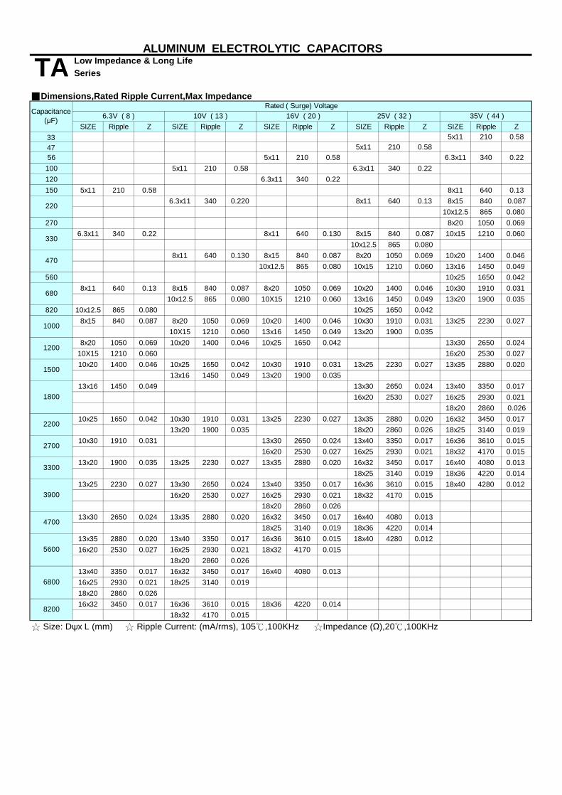
SIZE Ripple Z SIZE Ripple Z SIZE Ripple Z SIZE Ripple Z SIZE Ripple Z33 5x11 210 0.5847 5x11 210 0.5856 5x11 210 0.58 6.3x11 340 0.22
100 5x11 210 0.58 6.3x11 340 0.22120 6.3x11 340 0.22150 5x11 210 0.58 8x11 640 0.13
6.3x11 340 0.220 8x11 640 0.13 8x15 840 0.08710x12.5 865 0.080
270 8x20 1050 0.0696.3x11 340 0.22 8x11 640 0.130 8x15 840 0.087 10x15 1210 0.060
10x12.5 865 0.0808x11 640 0.130 8x15 840 0.087 8x20 1050 0.069 10x20 1400 0.046
10x12.5 865 0.080 10x15 1210 0.060 13x16 1450 0.049560 10x25 1650 0.042
8x11 640 0.13 8x15 840 0.087 8x20 1050 0.069 10x20 1400 0.046 10x30 1910 0.03110x12.5 865 0.080 10X15 1210 0.060 13x16 1450 0.049 13x20 1900 0.035
820 10x12.5 865 0.080 10x25 1650 0.0428x15 840 0.087 8x20 1050 0.069 10x20 1400 0.046 10x30 1910 0.031 13x25 2230 0.027
10X15 1210 0.060 13x16 1450 0.049 13x20 1900 0.0358x20 1050 0.069 10x20 1400 0.046 10x25 1650 0.042 13x30 2650 0.024
10X15 1210 0.060 16x20 2530 0.02710x20 1400 0.046 10x25 1650 0.042 10x30 1910 0.031 13x25 2230 0.027 13x35 2880 0.020
13x16 1450 0.049 13x20 1900 0.03513x16 1450 0.049 13x30 2650 0.024 13x40 3350 0.017
16x20 2530 0.027 16x25 2930 0.02118x20 2860 0.026
10x25 1650 0.042 10x30 1910 0.031 13x25 2230 0.027 13x35 2880 0.020 16x32 3450 0.01713x20 1900 0.035 18x20 2860 0.026 18x25 3140 0.019
10x30 1910 0.031 13x30 2650 0.024 13x40 3350 0.017 16x36 3610 0.01516x20 2530 0.027 16x25 2930 0.021 18x32 4170 0.015
13x20 1900 0.035 13x25 2230 0.027 13x35 2880 0.020 16x32 3450 0.017 16x40 4080 0.01318x25 3140 0.019 18x36 4220 0.014
13x25 2230 0.027 13x30 2650 0.024 13x40 3350 0.017 16x36 3610 0.015 18x40 4280 0.01216x20 2530 0.027 16x25 2930 0.021 18x32 4170 0.015
18x20 2860 0.02613x30 2650 0.024 13x35 2880 0.020 16x32 3450 0.017 16x40 4080 0.013
18x25 3140 0.019 18x36 4220 0.01413x35 2880 0.020 13x40 3350 0.017 16x36 3610 0.015 18x40 4280 0.01216x20 2530 0.027 16x25 2930 0.021 18x32 4170 0.015
18x20 2860 0.02613x40 3350 0.017 16x32 3450 0.017 16x40 4080 0.01316x25 2930 0.021 18x25 3140 0.01918x20 2860 0.02616x32 3450 0.017 16x36 3610 0.015 18x36 4220 0.014
18x32 4170 0.015
680
4700
5600
220
330
1800
3300
1500
2200
2700
35V ( 44 )25V ( 32 ) 16V ( 20 )
470
1000
6800
8200
☆ Size: Dψx L (mm) ☆ Ripple Current: (mA/rms), 105℃,100KHz ☆Impedance (Ω),20℃,100KHz
1200
3900
ALUMINUM ELECTROLYTIC CAPACITORS
TA Low Impedance & Long LifeSeries
■Dimensions,Rated Ripple Current,Max ImpedanceCapacitance
(μF)
Rated ( Surge) Voltage 6.3V ( 8 ) 10V ( 13 )
Series Rated Voltage Capacita Rated Code for Lead Wire Check orSeries Rated Voltage Capacita Rated Code for Lead Wire Check orSeries Rated Voltage Capacita Rated Code for Lead Wire Check orLead Wire Check orLead Wire Check orLead Wire Check orLead Wire Check orLead Wire Check orLead Wire Check or

Low Impedance & Long Life Series
■ Features:105℃ 4000~10000hrs Low Impedance and long Life ST■ Recommended Applications: Long Life Applicable for SMPS, Adaptor,Charger,Monitor/Computer SY
■ Specifications
-40 ~ +105℃6.3~100VDC
Rated Capacitance Range 2.2 ~ 15000μF Capacitance Tolerance ± 20 % at 120Hz , 20℃
I=0.01CV or 3(μA) , whichever is greater. (After rated voltage applied for 2 minutes )
I= Leakage Current (μA) C= Nominal Capacitance (μF) V= Rated Voltage (V) (20℃)
6.3 10 16 25 35 50 63 1000.22 0.19 0.16 0.14 0.12 0.14 0.14 0.14
When nominal capacitance is over 1000uF,Tanδ shall be added 0.02 to the listed value with increase of every 1000uF.Down size tanδ add 3%.
4 3 2 2 2 2 2 28 6 4 3 3 3 3 3
After applying rated voltage with rated ripple current for 4000~10000hours at 105℃,
Capacitance ChangeDissipation FactorLeakage Current
After placed at 105℃without voltage applied for 1000 hours,
■ Diagram of Dimensions
5 6.3 8 10 13 16 182.0 2.5 3.5 5.0 5.0 7.5 7.50.5 0.5 0.6 0.6 0.6 0.8 0.81.5 1.5 1.5 1.5 2.0 2.0 2.0
■ Multiplier for Ripple CurrentFrequency coefficient
0.98 1.00
1.001.001.00
1.000.750.85
1K 10K
0.900.94
100K
8000hrs10000hrs
0.950.95
6000hrs7000hrs
0.870.90
the capacitors shall meet the same requirement as load life.
16~100(V)
WV
initial specified value or less
Z-40℃ / Z+20℃
φ12.5~18φ
tanδ
WVZ(120Hz)
Z-25℃ / Z+20℃
6.3 100
0.95
ALUMINUM ELECTROLYTIC CAPACITORS
Dissipation Factor (MAX) (tanδ) (120Hz ,20℃)
Characteristics Operating Temperature Range
ST
Item
Rated Voltage Range
Leakage Current (MAX) (20℃)
4700μF Higher
2200to39000.850.75
220to560680to1800
0.500.60
■ Corresponding product to RoHS
50
Endurance
4000hrs5000hrs
φ8~10φ
Low Temperature StabilityImpedance Ratio (MAX)
16 25
6.8to180
Freq. (Hz)Cap(μF) 120
0.40
ψDPψda
Shelf Life
Within ± 25 % of initial value200% or less of initial specified value
6310
the capacitors shall meet the following requirements.
VDC6.3~10(V)
35
φ5~6.3φ

Low Impedance & Long Life Series
Size Ripple ESR Size Ripple ESR Size Ripple ESR Size Ripple ESR47 5x11 210 0.72056 5x11 210 0.720100 5x11 210 0.72 6.3x11 340 0.380 6.3x11 340 0.380150 5x11 210 0.720 8x11 640 0.200220 6.3x11 340 0.38 8x11 640 0.200 8x11 640 0.200330 6.3x11 340 0.380 8x15 701 0.160 8x15 840 0.160470 8x11 640 0.200 8x15 840 0.160 10x15 1210 0.084680 8x11 640 0.200 8x15 840 0.160 10x15 1210 0.084 10x20 1400 0.062820 8x15 840 0.160 10x25 1650 0.0521000 10x12 865 0.120 10x15 1210 0.084 10x20 1400 0.062 13x20 1900 0.046
8x20 1050 0.11010x15 1210 0.084
2200 10x20 1400 0.062 10x25 1650 0.052 13x25 2230 0.034 13x35 2880 0.0272700 10x25 1650 0.052 13x20 1900 0.046 13x30 2650 0.030 16x25 2930 0.0283300 13x20 1900 0.046 13x25 2230 0.034 13x35 2880 0.027 16x32 3450 0.0253900 13x25 2230 0.034 13x30 2650 0.030 13x40 3350 0.024 18x32 4170 0.0154700 13x30 2650 0.030 13x35 2880 0.027 16x32 3450 0.028 18x36 4280 0.014
13x40 3350 0.024 16X36 3610 0.01816x25 2930 0.028 18x32 4170 0.015
13x40 3350 0.024 18x36 4220 0.01416x25 2930 0.028
8200 16x32 3450 0.025 16X36 3610 0.01810000 16X36 3610 0.018 18x36 4220 0.01412000 18x32 4170 0.01515000 18x36 4220 0.014
Size Ripple ESR Size Ripple ESR Size Ripple ESR Size Ripple ESR
2.2 5x11 20 10.00
3.3 5x11 27 8.500
4.7 5x11 30 8.000
6.8 5x11 45 7.50010 5x11 120 3.50 5x11 55 2.300 6.3x11 55 5.00015 6.3x11 70 5.00022 5x11 210 2.300 8x11 85 2.70033 5x11 210 0.720 6.3x11 340 1.200 6.3x11 115 1.200 8x11 95 2.50047 6.3x11 340 0.380 6.3x11 340 1.200 8x15 150 1.80056 8x11 232 0.630 8x20 200 1.50068 10x15 230 1.30082 10x20 250 1.200100 8x11 555 0.630 10x20 330 0.950
8x15 730 0.450
150 8x11 640 0.200 8x20 910 0.330 13x20 460 0.900180 10x20 466 0.210220 8x15 840 0.160 10x16 1050 0.310 10x25 531 0.200 13x25 640 0.600
10x30 663 0.15013x20 690 0.160
330 10x20 1400 0.062 10x20 1400 0.210 13x25 784 0.120 16x25 720 0.57010x30 1690 0.150 16x32 770 0.55013x20 1660 0.160 18x25 840 0.500
560 13x25 1950 0.120 13x35 1050 0.08310x30 1910 0.04413x20 1900 0.046
820 13x25 2230 0.045 13x35 2510 0.083 16x32 1570 0.054 18x40 1850 0.1301000 13x25 2230 0.045 16x25 2555 0.073 16X36 1790 0.045 18x40 1850 0.1301200 13x30 2650 0.030 16x32 3010 0.054 16x40 2020 0.0401500 13x35 2880 0.027 16X36 3150 0.0451800 13x40 3350 0.024 18x32 3635 0.0472200 16x32 3450 0.025 18x36 3680 0.0402700 16X36 3610 0.022 18x40 3800 0.0363300 18x36 4220 0.020
18x36 1400 0.180
100
10x25 400 0.800
13x40 1180 0.071
13x30 905 0.100
5600 13x35
0.052
13x30 2310 0.100680
470 10x25 1650
50
2880 0.027
16x32 3450 0.025
Rated Voltage(V)
■Dimensions,Rated Ripple Current
☆ Size: Dψx L (mm) ☆ Ripple Current: 105℃,100KHz(mA/rms) ☆ESR(Ω):25℃,100KHz
35
13x251500 10x20 1400 0.062
Capacitance(μF)
ALUMINUM ELECTROLYTIC CAPACITORS
0.310
STCapacitance
(μF)
Rated Voltage(V)
6.3 10 16 25
63
270
120 10x16 357
2230 0.03410x25 1650 0.052
6800

■ Features: 105℃ 1000~2000 hours ,Lower ESR and higher ripple current SZ■ Recommended Applications: Applicable for switching regulator of computer,
SC■ Corresponding product to RoHS
Rated Capacitance Range
tanδ shall be added 0.02 to the listed value with increase of every 1000μF.
the capacitors shall meet the following requirements.
the capacitors shall meet the same requirement as Endurance.
■ Diagram of Dimensions
ψD 8 10P 3.5 5.0ψd 0.6 0.6a 1.5 1.5
■ Multiplier for Ripple Current Frequency coefficient
Frequency (Hz) 120 1K
Within ± 25 % of initial value
Not more than the specified value
After placed at 105℃ without voltage applied for 1000 hours,
Not more than 200% of specified value Leakage Current
10 16
0.16
3
tanδ
Low Temperature Stability WVZ(120Hz)
Z-25℃ / Z+20℃ Impedance Ratio (MAX)
10K 100K0.5 1.0
6.3
Capacitance Change
After applying rated voltage with ripple current for 2000 hours at 105℃,3
6.3
ALUMINUM ELECTROLYTIC CAPACITORS
Capacitance Tolerance
SZ
Item -40 ~ +105℃
Ultra Low ESRSeries
Operating Temperature Range Rated Voltage Range
■ Specifications
Low E.S.R
2
± 20 % at 120Hz , 20℃
especially for high frequency
Leakage Current (MAX)(20℃)
10 Dissipation Factor (MAX) (tanδ) (120Hz ,20℃)
Characteristics
6.3 ~ 16VDC470 ~ 3300 μF
2
I=0.03CV ,(After rated voltage applied for 2 minutes )
2
0.190.22When nominal capacitance is over 1000μF,
16WV
Z-40℃ / Z+20℃
0.8 0.9
Shelf Life
Dissipation Factor Endurance
*If dimension is down size,Endurance will be less 1000 hours than standard.
Factor
3
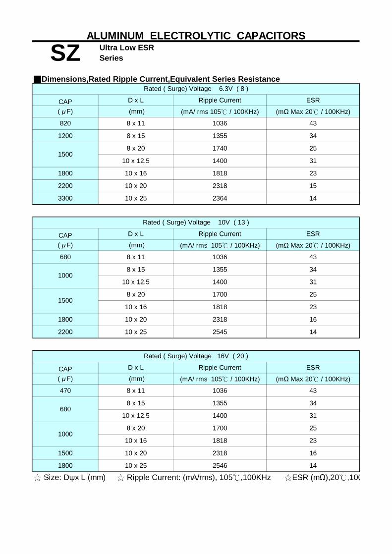
Ultra Low ESR
CAP D x L Ripple Current ESR
( μF) (mm) (mA/ rms 105℃ / 100KHz) (mΩ Max 20℃ / 100KHz)
820 8 x 11 1036 43
1200 8 x 15 1355 34
8 x 20 1740 25
10 x 12.5 1400 31
1800 10 x 16 1818 23
2200 10 x 20 2318 15
3300 10 x 25 2364 14
CAP D x L Ripple Current ESR
( μF) (mm) (mA/ rms 105℃ / 100KHz) (mΩ Max 20℃ / 100KHz)
680 8 x 11 1036 43
8 x 15 1355 34
10 x 12.5 1400 31
8 x 20 1700 25
10 x 16 1818 23
1800 10 x 20 2318 16
2200 10 x 25 2545 14
CAP D x L Ripple Current ESR
( μF) (mm) (mA/ rms 105℃ / 100KHz) (mΩ Max 20℃ / 100KHz)
470 8 x 11 1036 43
8 x 15 1355 34
10 x 12.5 1400 31
8 x 20 1700 25
10 x 16 1818 23
1500 10 x 20 2318 16
1800 10 x 25 2546 14
☆ Size: Dψx L (mm) ☆ Ripple Current: (mA/rms), 105℃,100KHz ☆ESR (mΩ),20℃,100KHz
1000
680
1000
Rated ( Surge) Voltage 10V ( 13 )
Rated ( Surge) Voltage 16V ( 20 )
1500
ALUMINUM ELECTROLYTIC CAPACITORS
■Dimensions,Rated Ripple Current,Equivalent Series ResistanceRated ( Surge) Voltage 6.3V ( 8 )
SZ Series
1500

Higher temperature range & Long LifeSeries
AK■ Features:125℃ 2000~5000hrs, High Temperature and Long Life■ Recommended Applications: Higher temperatureHigher temperature Applicable for Electronic Ballast,Lighting Ballast AH
■ Specifications
Rated Capacitance Range Capacitance Tolerance
WV 10 16 25 50 63 160~250 350~450tanδ 0.19 0.16 0.14 0.14 0.14 0.20 0.24
When nominal capacitance is over 1000uF,tanδ shall be added 0.02 to the listed value with increase of every 1000uF.Down Size tanδ added 0.03.
Z-25℃ / Z+20℃ 3 2 2 2 2 3 6Z-40℃ / Z+20℃ 6 4 4 4 3 - -
After applying rated voltage for 2000~5000hours at 125℃,
After leaving capacitors under no load at 125℃ for 1000 hours.
■ Diagram of Dimensions
ψD 8 13 16 18P 3.5 5.0 7.5 7.5ψd 0.6 0.6 0.8 0.8a 1.5 2.0 2.0 2.0
■ Multiplier for Ripple Current
CAP≦1010<CAP≦100100<CAP≦10001000<CAPCAP≦33CAP≧47
1200.40
1K 50K~100K0.75 1.00
10K0.90
16
the capacitors shall meet the following requirements.
25 50 63 160~250 350~450
■ Corresponding product to RoHS
-40 ~ +125℃ -25 ~ +125℃10~63VDC 160~450VDC47~ 4700μF
35
1~150μF± 20 % at 120Hz , 20℃
Frequency coeffcientFrequency (Hz)
ALUMINUM ELECTROLYTIC CAPACITORS
Dissipation Factor (MAX) (tanδ) (120Hz ,20℃)
Characteristics Operating Temperature Range
AK
Item
Rated Voltage Range
Low Temperature Stability Impedance Ratio (MAX)
Leakage Current
Capacitance ChangeDissipation Factor
WVZ(120Hz) 10
1.000.60 0.880.50 0.85 1.000.95
Shelf LifeCapacitance Change
Dissipation FactorLeakage Current
8Φ
Endurance
2000Hrs
≦initial specified value or less
Within ± 30 % of initial value
105.00.61.5
3000Hrs≧13Φ10Φ
5000Hrs
≦ 500% of the initial specified value≦300% of initial specified value≦500% of initial specified value
0.12
35
24
Within ± 30 % of initial value≦300% of initial specified value
Within ± 20 % of initial value≦ 200% of the initial specified value
≦ initial specified value
2000Hrs
Within ± 20 % of initial value≦ 200% of the initial specified value
160~450WV1.001.00
0.960.98
10~63WV1.00
0.75 0.901.801.50
1.501.30
1.751.40
Leakage Current (MAX) (20℃) I=0.04CV+100 uA (CV>1000)I=0.01CV or 3(μA) ,whichever is greater.
(After rated voltage applied for 2 minutes )I= Leakage Current (μA) C= Nominal Capacitance (μF) V= Rated Voltage (V) (20℃)
I=0.1CV+40 uA (CV≦1000)

Higher temperature range & Long LifeSeries
Size Ripple Size Ripple Size Ripple Size Ripple
100 8x11 340 10x12.5 340
220 8x11 340 8x11 340 10x12.5 500 10x16 500
330 10x12.5 500 10x12.5 500 10x16 630 10x20 770
470 10x16 630 10x20 770 10x20 770 13x20 920
1000 10x20 770 13x20 920 13x25 1250 16x25 1380
2200 13x25 1250 16x25 1380 16x32 1450
3300 16x25 1380 16x32 1450
4700 16x32 1450 18x32 1720
Size Ripple Size Ripple
47 8x11 245 8x11 245
100 10x12.5 415 10x15 455
220 10x20 491 13x20 665
330 13x20 665 13x25 995
470 13x25 995 16x25 1000
1000 16x32 1280
☆ Size: Dψx L (mm) ☆ Ripple Current: 125℃,100KHz(mA/rms)
Size Ripple Size Ripple Size Ripple Size Ripple Size Ripple Size Ripple1.0 8x11 25 10x12.5 28 8x16 252.2 8x11 28 10x12.5 32 10x16 35 10x16 323.3 8x11 28 8x11 28 10x12.5 32 10x16 45 10x16 42 10x20 404.7 10x12.5 40 10x12.5 40 10x16 45 10 × 20 53 10 × 20 53 10 × 25 5810 10x16 60 10 × 20 78 10 × 20 78 10 × 25 85 10 × 25 86 13 × 20 8622 10 × 20 115 10 × 25 126 13 × 20 128 13 × 25 139 13 × 30 142 16 × 25 15433 10 × 25 154 13 × 20 157 13 × 25 171 16 × 25 189 16 × 25 189 16 × 32 20347 13 × 20 187 13 × 25 204 16 × 25 225 16 × 32 243 16 × 32 24368 13 × 25 245 16 × 20 250 16 × 32 292100 16 × 25 329 16 × 25 329150 16 × 32 434
☆ Size: Dψx L (mm) ☆ Ripple Current: 125℃,120Hz(mA/rms)
200(250)
63(79)
Rated Voltage(V)
250(300)
ALUMINUM ELECTROLYTIC CAPACITORS
■Dimensions,Rated Ripple Current
AKCapacitance
(μF)
Rated Voltage(V)
10(13) 16(20)
350(400)
25(32) 35(44)
50(63)Capacitance(μF)
400(450) 450(500)Capacitance
(μF)
Rated Voltage(V)160(200)

■ Features: 105℃ 2000 hours ;Wide temperature range;High Ripple SQ■ Recommended Applications :AV(TV, Video, Audio); Monitor/Computer;
OA/HA/Communication; Converter/Inverter; SHEnergy saving lamp; PFC circuit;SMPS; Ballast; Adapter
■ Corresponding product to RoHS
■ Specifications
160 200 250 350 400 4500.15 0.15 0.15 0.24 0.24 0.24
Impedance Ratio (MAX) 3 3 3 3 3 36 6 6 6 6 6
the capacitors shall meet the following requirements.
■ Diagram of Dimensions
ψD 10 13 16 18
P 5 5 7.5 7.5
a 1.5 2 2 2
■ Multiplier for Ripple Current
Frequency coefficient
1.00≧33μF 1.000.60 0.70 0.90 0.95
Coefficient<33μF 0.45 0.55 0.75 0.85
Frequency (Hz) 50 120 1K 10K 100K
Low Temperature Stability
Coefficient
Capacitance Change
Shelf Life
Leakage Current
Endurance
WV Z (120Hz)
After apply rated voltage with rated ripple current for 2000hrs at 105℃ ,
Within ± 20 % of initial value
≧33μF
ψd 0.6
After leaving capacitors under no load at 105℃ for 1000 hours,
0.8
the capacitors shall meet the same requirement as Endurance.
Frequency (Hz)
<33μF
0.851.80
ALUMINUM ELECTROLYTIC CAPACITORS
SQ
I= Leakage Current (μA) C= Nominal Capacitance (μF) V= Rated Voltage (V)
Operating Temperature Range Item Characteristics
-40~+105℃ Rated Voltage Range(WV)
For adapter and power supply applications
Dissipation Factor (MAX) (tanδ) (120Hz,20℃)
Series
160 ~ 450VDC2.2 ~ 220μF Rated Capacitance Range
tanδ
Leakage Current (MAX) (20℃)
± 20 % at 120Hz , 20℃ Capacitance Tolerance
Not More than the specified value
250 350 400
Z(-25℃) / Z(20℃)Z(-40℃) / Z(20℃)
200
(After rated voltage applied for 3 minutes)
High Ripple
Not more than 200% of the specified valueDissipation Factor
I≦0.03CV +10μA
WV
160 450
1.00
50
0.80
120
1.00
0.8
1.28 1.35
100K
1.40
1K 10K
0.6
1.36 1.54

120Hz 100KHz 120Hz 100KHz 120Hz 100KHz
10x20 120 22010x20 195 350 10x20 195 350 13x25 165 30013x20 315 450 13x20 365 520 13x25 280 40013x25 420 600 13x25 420 600 16x25 505 72013x25 420 600 16x25 665 950 16x32 570 81016x25 665 950 16x32 840 1200 18x36 735 105018x36 980 1400
120Hz 100KHz 120Hz 100KHz 120Hz 100KHz
10x16 30 50 10x16 80 140 10x16 60 110
10x16 35 60 10x20 110 195 10x20 75 135
10x20 45 78 10x25 120 220 13x20 105 190
13x20 75 130 10x16 135 243 13x25 140 250
13x25 200 360
16x25 115 205 13x20 240 432 13x20 180 324
13x25 265 477 13x25 200 360
16x25 315 570 16x32 265 480
16x32 180 255 16x32 490 700 16x25 350 500
18x36 455 650
18x32 225 320 16x25 350 490 16x25 380 532
18x32 600 860
16x30 510 714 18x25 470 658
16x32 550 770
18x36 520 720
18x45 370 530 18x32 680 952 18x40 620 860
18x32 750 1050 18x40 650 910
18x45 720 100018x36 800 1120
☆ Size: Dψx L (mm) ☆ Ripple Current : mA/rms,105℃
33
3.3
4.7
82
47
120
150
100
10
22
68
350(400) 400(450)
2.2
ψDxLRipple
ψDxLRipple
220
Capacitance(μF)
ψDxLRipple
Rated ( Surge ) Voltage
100
10
22
33
47
Rated ( Surge ) Voltage
Capacitance(μF)
160(200)
ψDxLψDxLRipple
200(250)
450(500)
ψDxLRipple
68
ALUMINUM ELECTROLYTIC CAPACITORS
SQ For adapter and power supply applicationsSeries
■Dimensions, Rated Ripple Current
Ripple
250(300)

High Ripple and long lifeSeries
■ Features: High temperature life time 5000 hours at 105℃ SG■ Recommended Applications : High ripple current for Electronic Ballast , Long Life
Power Supply…etc SQ■ Corresponding product to RoHS
■ Specifications
Rated Capacitance Range
160 200 250 350 400 450 5000.15 0.15 0.15 0.20 0.24 0.24 0.24
3 3 3 5 5 6 66 6 6 6 6 — —
the capacitors shall meet the following requirements.
13 16 18 225.0 7.5 7.5 10.00.6 0.8 0.8 0.82.0 2.0 2.0 2.0
■ Multiplier for Ripple Current Frequency coefficient
Item Characteristics -40~+105℃ -25~+105℃
Impedance Ratio (MAX)
450~500VDC3.3 ~ 100μF
I=0.06CV + 10(μA) , (After rated voltage applied for 2 minutes) Leakage Current (MAX) ( 20℃ )
Dissipation Factor (MAX) (tanδ) (120Hz ,20℃)
Capacitance Tolerance
500450
ALUMINUM ELECTROLYTIC CAPACITORS
Rated Voltage Range 160 ~ 400VDC4.7 ~ 330μF± 20 % at 120Hz , 20℃
SG
Operating Temperature Range
WVtanδ
Shelf Life
5.010
■ Diagram of Dimensions
Low Temperature Stability
EnduranceDissipation Factor
350 400200
initial specified value or less
WV Z (120Hz) 160
Z-40℃ / Z+20℃Z-25℃ / Z+20℃
250
Not more than 200% of the specified value
1201.20300
1.40
Capacitance Change
After applying rated voltage with rated ripple current for 5000 hours at 105℃ ,
After placed at 105℃ without voltage applied for 1000 hours,
Leakage Current
Within ± 20 % of initial value
the capacitors shall meet the same requirement as Endurance.
a 1.5
10K~100K
ψDP
Frequency (Hz)
ψd 0.6
1K50,60
500V1.60
0.75 1.00 1.20 1.35 1.50160~450V 0.80 1.00
Upgrade
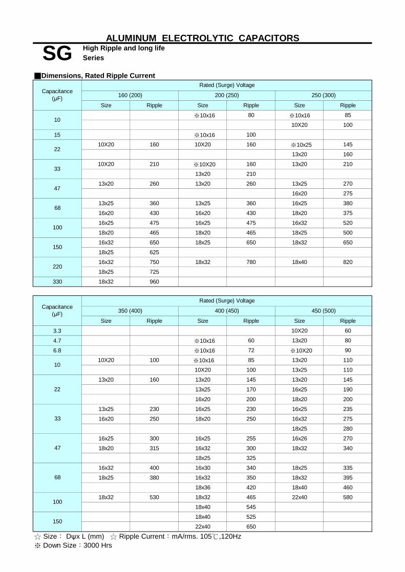
High Ripple and long lifeSeries
■Dimensions, Rated Ripple Current
Size Ripple Size Ripple Size Ripple
※10x16 80 ※10x16 85
10X20 100
15 ※10x16 100
10X20 160 10X20 160 ※10x25 145
13x20 160
10X20 210 ※10X20 160 13x20 210
13x20 210
13x20 260 13x20 260 13x25 270
16x20 275
13x25 360 13x25 360 16x25 380
16x20 430 16x20 430 18x20 375
16x25 475 16x25 475 16x32 520
18x20 465 18x20 465 18x25 500
16x32 650 18x25 650 18x32 650
18x25 625
16x32 750 18x32 780 18x40 820
18x25 725
330 18x32 960
Size Ripple Size Ripple Size Ripple
3.3 10X20 60
4.7 ※10x16 60 13x20 80
6.8 ※10x16 72 ※10X20 90
10X20 100 ※10x16 85 13x20 110
10X20 100 13x25 110
13x20 160 13x20 145 13x20 145
13x25 170 16x25 190
16x20 200 18x20 200
13x25 230 16x25 230 16x25 235
16x20 250 18x20 250 16x32 275
18x25 280
16x25 300 16x25 255 16x26 270
18x20 315 16x32 300 18x32 340
18x25 325
16x32 400 16x30 340 18x25 335
18x25 380 16x32 350 18x32 395
18x36 420 18x40 460
18x32 530 18x32 465 22x40 580
18x40 545
18x40 525
22x40 650
68
☆ Size︰ Dψx L (mm) ☆ Ripple Current︰mA/rms. 105℃,120Hz※ Down Size︰3000 Hrs
10
33
47
150
100
22
220
Capacitance(μF)
Rated (Surge) Voltage
350 (400) 400 (450) 450 (500)
22
33
47
150
68
100
10
ALUMINUM ELECTROLYTIC CAPACITORS
SGCapacitance
(μF)
Rated (Surge) Voltage
160 (200) 200 (250) 250 (300)

High Ripple and long lifeSeries
■Dimensions, Rated Ripple Current
Size Ripple
4.7 10X20 70
6.8 13X20 100
10 12.5X25 130
16X25 225
18X20 220 16X32 305
18X25 295
16x36 430
18x32 435
18x32 530
18x36 555
18x40 640
22x35 675
100 22x35 745
120 22x40 865
150 22x45 1020
ALUMINUM ELECTROLYTIC CAPACITORS
SGCapacitance
(μF) 500 (550)
Rated (Surge) Voltage
33
47
22
※ Down Size︰3000 Hrs☆ Size︰ Dψx L (mm) ☆ Ripple Current︰mA/rms. 105℃,120Hz
68
82

Series
■ Features: High temperature and long life at 105℃ for 8000 to 10000 hours SP■ Recommended Applications:Applicable for Electronic Ballast Long Life■Corresponding product to RoHS
SG■ Specifications
Rated Capacitance Range
ψD 10 13 16 18P 5.0 7.5 7.5ψd 0.6 0.8 0.8a 1.5 2.0 2.0
■ Multiplier for Ripple Current
Frequency coefficient
Z-40℃ / Z+20℃Z-25℃ / Z+20℃
6 —
WVZ(120Hz)
4500.24
3
0.24
5 6
160 200 400
SP
Operating Temperature Range Item Characteristics
-40~+105℃ -25~+105℃
Miniature and long life
Leakage Current(MAX)(20℃) Capacitance Tolerance
Rated Voltage Range 160 ~ 400VDC 450VDC3.3 ~ 330μF
tanδ
± 20 % at 120Hz , 20℃
636
Within ± 20 % of initial value
Impedance Ratio (MAX)
Dissipation FactorCapacitance Change
applies for 10000 hours (8000 hours for ψ10) at 105℃.
The follwing sprcifications shall be satisfied when the capacitors are restored to 20℃ after subjected to DC voltage with the max ripple current is
Not more than 200% of the specified value
ALUMINUM ELECTROLYTIC CAPACITORS
Leakage Current
After placed at 105℃ without voltage applied for 1000 hours, Shelf Lifethe capacitors shall meet the same requirement as Endurance.
Endurance
WV
Low Temperature Stability
160
Frequency (Hz)Coefficient
I=0.04CV + 100(μA) ,(After rated voltage applied for 2 minutes )
Dissipation Factor (MAX) (tanδ) (120Hz ,20℃) 0.20
2000.20
400
450
2.00.6
initial specified value or less
■ Diagram of Dimensions
5.012.5
10K 100K1.0 1.6 1.8 2.0120 1K

Series
■Dimensions,Rated Ripple Current
120Hz 100KHz 120Hz 100KHz
22 10x20 220 440
10x20 250 500 10x20 260 520
12.5x20 290 580
10x20 290 580 13x20 330 660
12.5x20 330 660
13x25 360 720 13x25 360 720
16x20 380 760 16x20 380 760
13x25 485 970 16x25 560 1120
16x20 560 1120
16x25 560 1120
18x20 560 1120
16x25 600 1200 16x32 640 1280
16x32 650 1300
18x25 650 1300
16x32 650 1300
18x25 650 1300
330 18x36 690 1380
120Hz 100KHz 120Hz 100KHz
3.3 10x16 50 100
4.7 10x20 70 140
10x20 75 150 10x20 75 150
12.5x20 90 180
10 10x20 90 180 12.5x20 155 310
16x20 150 300 16x25 280 560
18x20 275 550
16x25 260 520 16x32 310 620
18x25 295 590
16x32 350 700 16x36 440 880
18x32 440 880
68 18x32 435 870
200 (250)
SizeRipple
☆ Size︰ Dψx L (mm) ☆ Ripple Current: (mA/rms),105℃
6.8
22
33
150
Ripple
47
ALUMINUM ELECTROLYTIC CAPACITORS
Rated ( Surage ) Voltage
Rated ( Surage ) Voltage 400 (450)
33
47
68
100
Miniature and long life
450 (500)
SP
Capacitance (μF)
Capacitance (μF)
Size
160 (200)
220
SizeRipple
SizeRipple

Long Life Series
■ 105℃ 10000~12000hrs long Life SULong Life
■ Recommended Applications: Electronic lighting and power SP
■ Specifications
-25 ~ +105℃160~450VDC
Rated Capacitance Range 3.3 ~ 330μF
Capacitance Tolerance ± 20 % at 120Hz , 20℃
I=0.04CV +100μA . (After rated voltage applied for 2 minutes )
I= Leakage Current (μA) C= Nominal Capacitance (μF) V= Rated Voltage (V) (20℃)
160 200 250 350 400 450
0.15 0.15 0.15 0.20 0.20 0.20
3 3 3 5 5 6
After applying rated voltage with rated ripple current for 10000~12000hours at 105℃,
Capacitance Change ΦD×LDissipation Factor 10ΦLeakage Current ≧13Φ
After placed at 105℃without voltage applied for 1000 hours,
■ Diagram of Dimensions
■ Multiplier for Ripple Current
18.07.50.82.0
16.07.50.82.0
10.05.00.61.5
13.05.00.62.0
10K
Leakage Current (MAX) (20℃)
0.9
Low Temperature StabilityImpedance Ratio (MAX)
160 200
ψda
Shelf Life
100K1.0
12000
the capacitors shall meet the same requirement as load life.
1200.5
1KFrequency (Hz)
ψDP
ALUMINUM ELECTROLYTIC CAPACITORS
Dissipation Factor (MAX) (tanδ) (120Hz ,20℃)
Characteristics Category Temperature Range
SU
Item
Rated Voltage Range
Frequency coeffcient
Coefficient
400
Within ± 20 % of initial value200% or less of initial specified value
initial specified value or less
250 350
0.8
the capacitors shall meet the following requirements.
10000
450
Endurance
WV
tanδ
WVZ(120Hz)
Z-25℃ / Z+20℃
Life Time(hrs)
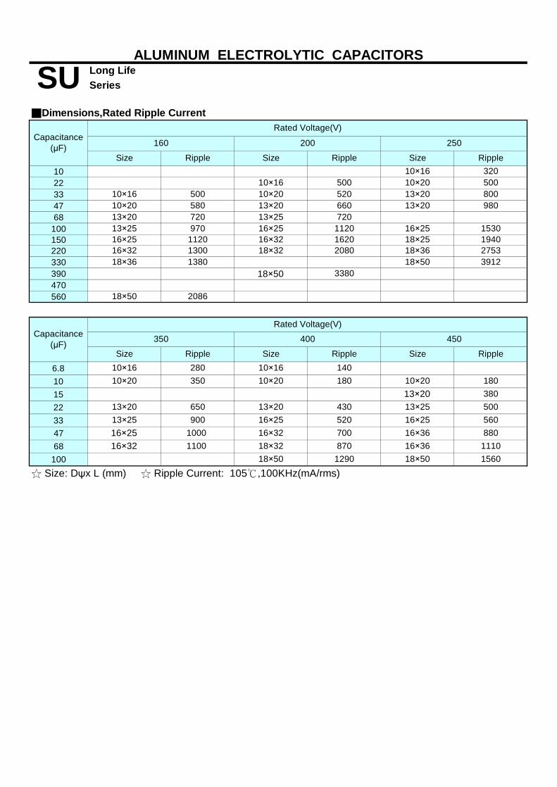
Long Life Series
1022334768
100150220330390470560
6.8101522334768
100
3912
720 720
18×25 194016×25
1120970
18×36 1380 18×502753
16×25 16×32 162016×32 1300 18×32 2080 18×36
153013×20 13×25
13×20 98013×20 660
13×25 112016×25
10×16 50010×20 580
10×20 520
250
500 10×20 500
Size Ripple10×16 320
13×20 800
160
Ripple
10×16
ALUMINUM ELECTROLYTIC CAPACITORS
■Dimensions,Rated Ripple Current
Size Ripple Size Ripple Size
200
Size Ripple
☆ Size: Dψx L (mm) ☆ Ripple Current: 105℃,100KHz(mA/rms)
SUCapacitance
(μF)
Rated Voltage(V)
Rated Voltage(V)
350 400 450Capacitance(μF)
Size
Ripple10×16 280 10×16 140
650 13×20 430 13×25 500
10×20 35013×2010×20
380
18×50 2086
16×25 56013×25 900 16×25 520
180
13×20
18×50 3380
10×20 180
16×25 1000
18×50 1290870 16×36 111018×3216×32 1100
18×50 1560
16×32 700 16×36 880

Ultra Long Life Series
■ 105℃ 12000~20000hrs Ultra long Life
■ Recommended Applications: For LED Lightingr
■ Specifications
-40 ~ +105℃160~400VDC
Rated Capacitance Range 1.0 ~ 33μF
Capacitance Tolerance ± 20 % at 120Hz , 20℃
I= Leakage Current (μA)
C= Nominal Capacitance (μF)
V= Rated Voltage (V) (20℃)
160 200 400
0.24 0.24 0.24
3 3 6
8 8 10
After applying rated voltage with rated ripple current for 12000~20000hours at 105℃,
After placed at 105℃without voltage applied for 1000 hours,
■ Diagram of Dimensions
6.3 8.0 10.02.5 3.5 5.00.5 0.6 0.62.0 2.0 2.0
■ Multiplier for Ripple Current
1.9
120001500020000
Coefficient2.01~5.6μF
22~33μF6.8~18μF 1.0
Dissipation Factor 300% or less of initial specified value
Leakage Current initial specified value or less
10K
1.7
CV>1000
I=0.04CV +100μA (1 minutes )
I=0.02CV +25μA (5 minutes )
tanδ
Z-40℃ / Z+20℃
I=0.1CV +40μA (1 minutes )
Life Time(hrs)
1.6
Low Temperature StabilityImpedance Ratio (MAX)
160 200
ψda
Shelf Life
WV
1.8
the capacitors shall meet the same requirement as load life.
120
1.0
1KFrequency (Hz)
ψDP
1.01.5
100K
Z-25℃ / Z+20℃
ΦD×L6.3x11,8X9,10X9
I=0.03CV +15μA (5 minutes )
Capacitance Change
10x16
the capacitors shall meet the following requirements.
WVZ(120Hz)
ALUMINUM ELECTROLYTIC CAPACITORS
Dissipation Factor (MAX) (tanδ) (120Hz ,20℃)
Characteristics Category Temperature Range
TE
Item
Rated Voltage Range
CV≦1000
Leakage Current (MAX) (20℃)
Endurance
8x11,10x12.5
Frequency coeffcient
Within ± 30 % of initial value
400
1.4
1.6 1.8
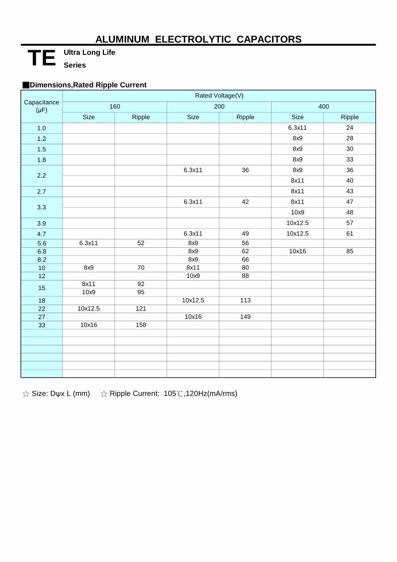
Ultra Long Life
Series
1.0
1.2
1.5
1.8
2.7
3.9
4.75.66.88.21012
18222733
3.36.3x11
2.26.3x11
8x9 33
6.3x11 24
8x9 28
8x9 30
36
47
61
85
40
43
48
57
8x9
8x11
10x12.5
10x16
8x11
8x11
10x9
10x12.5
36
42
49
62
6.3x11
8x9
10x16 149
113121
10x9
10x9 88
15
8x9
10x12.5
15810x16
10x12.5
80
8x11
66
95
8x9
92
Ripple
6.3x11
8x9 70 8x11
52 56
400
Size
ALUMINUM ELECTROLYTIC CAPACITORS
■Dimensions,Rated Ripple Current
200
Size Ripple Size Ripple
160
☆ Size: Dψx L (mm) ☆ Ripple Current: 105℃,120Hz(mA/rms)
TE
Capacitance(μF)
Rated Voltage(V)

Miniature and general purposeSeries
■ Features: 105℃ 2000 hours■ Recommended Applications: For high quality , reliability application, high CV product■ Suitable for slim application■Corresponding product to RoHS
■ Specifications
Rated Capacitance Range Capacitance Tolerance
250 350~4500.15 0.20
4 6
the capacitors shall meet the following requirements.
the capacitors shall meet the same requirement as Endurance.
■ Diagram of Dimensions
ψD 8 12.5p 3.5 5.0ψd 0.6 0.6a 2.0 2.5
■ Multiplier for Ripple CurrentFrequency coefficient
0.6
5.0
1K
ALUMINUM ELECTROLYTIC CAPACITORS
Low Temperature Stability Impedance Ratio (MAX)
Dissipation Factor (MAX) (tanδ) (120Hz ,20℃)
Rated Voltage Range
Item
TH
Leakage Current (MAX)(20℃)
160 ~ 450V ALL Cap (μF) 1.00Frequency (Hz)
1.25 1.40300120
Characteristics
WVtanδ
1.6010K
2.0
Within ± 20 % of initial valueNot more than 200% of the specified value
Capacitance Change
250 350~450
10.0
Z-25℃ / Z+20℃
WV Z(120Hz)
After applying rated voltage for 2000 hours at 105℃
Dissipation FactorLeakage Current
Shelf Life
initial specified value or less
Operating Temperature Range250 ~ 450VDC -25~+105℃
10 ~ 150μF± 20 % at 120Hz , 20℃
I=0.03CV+10(μA) ,After rated voltage applied for 2 minutes
After leaving capacitors under no load at 105℃ for 1000 hours.
Endurance

Miniature and general purposeSeries
■Dimensions,Rated Ripple Current
Size Ripple Size Ripple Size Ripple Size Ripple Size Ripple10 12 8x30 11515 8x30 140 8x35 170 8x35 150 8x35 135
8x30 200 8x35 180 8x40 220 8x40 195 8x42 19010x30 190
8x35 215 8x40 210 8x45 250 8x45 220 8x45 21010x35 250 10x35 220 10x35 210
8x35 240 8x42 240 8x50 295 8x50 285 8x52 29010x40 295 10x40 285 10x42 290
8x40 260 10x40 280 8x52 320 10x42 310 10x45 32010x30 275 10x40 320 12.5x35 320 12.5x40 3308x45 310 10x45 325 10x45 355 10x45 350 10x50 360
12.5x40 365 12.5x40 350 12.5x42 37010x40 350 10x50 380 10x50 405 10x52 390 12.5x45 415
12.5x40 405 12.5x42 39010x40 400 12.5x40 430 10x55 460 12.5x45 450 12.5*50 475
12.5x45 46082 10x45 450 12.5x45 500 12.5x50 525 12.5x52 535 12.5x55 535
100 10x50 525 12.5x50 630 12.5x55 620150 12.5x45 725
☆ Size: Dψx L (mm) ☆ Ripple Current: (mA/rms). 105℃,120Hz
TH
400 (450) 450 (500)Capacitance
(μF)
Rated (Surge) Voltage
420(470)250 (300) 350 (400)
39
47
56
68
ALUMINUM ELECTROLYTIC CAPACITORS
22
27
33

High Ripple and long lifeSeries
■ Features: High temperature life time 5000 hours at 105℃■ Recommended Applications : High ripple current for Electronic Ballast ,
Power Supply…etc■ Suitable for slim application■ Corresponding product to RoHS
■ Specifications
Rated Capacitance Range
250 350 400 420、4500.15 0.20 0.24 0.24
3 5 5 6
the capacitors shall meet the following requirements.
■ Multiplier for Ripple Current Frequency coefficient
10 ~ 150μF± 20 % at 120Hz , 20℃
8
I=0.06CV + 10(μA) , (After rated voltage applied for 2 minutes)
250 350
2.0
Leakage Current
■ Diagram of Dimensions
a 2.0
ALUMINUM ELECTROLYTIC CAPACITORS
Rated Voltage Range
TG
Operating Temperature Range Item Characteristics
-25~+105℃250 ~ 450VDC
Capacitance Tolerance
EnduranceDissipation Factor
Capacitance Change
Leakage Current (MAX) ( 20℃ )
Dissipation Factor (MAX) (tanδ) (120Hz ,20℃)
420、450
Z-25℃ / Z+20℃
WV Z (120Hz)
Coefficient
400
Within ± 20 % of initial valueNot more than 200% of the specified value
initial specified value or less
ψDP
Frequency (Hz)
3.50.6
the capacitors shall meet the same requirement as Endurance. Shelf Life
105.0
WVtanδ
12.5
0.801K50,60 120
Low Temperature Stability Impedance Ratio (MAX)
After applying rated voltage with rated ripple current for 5000 hours at 105℃ ,
ψd 0.6
After placed at 105℃ without voltage applied for 1000 hours,
5.00.6
2.5
10K~100K1.601.401.20
3001.00

High Ripple and long lifeSeries
■Dimensions, Rated Ripple Current
10
12 8x35 110
15 8x35 120 8x35 110 8x35 105 8x40 130
8x30 130 8x40 150 8x40 140 8x40 135 8x45 165
10x35 165
8x32 150 8x45 170 8x45 165 8x45 155 8x52 195
10x35 165 10x35 155 10x40 195
8x35 170 8x50 200 8x50 190 8x50 185 10x45 230
10x40 190 10x40 185 12.5x35 230
8x42 200 10x45 235 10x45 220 10x45 215 10x50 265
12.5x35 215 12.5x40 265
8x45 220 10x50 270 10x50 255 10x50 245 10X52 295
12.5x40 255 12.5x40 245 12.5x45 310
56 10x42 300 12.5x40 300 12.5x45 300 12.5x45 290 12.5x50 355
68 10x45 330 12.5x45 350 12.5X50 350 12.5x50 335 12.5x55 410
82 10x50 390 12.5x50 400 12.5x55 400 12.5x55 385
100 12.5x42 440 12.5x55 460
120 12.5x45 490
150 12.5x50 560
☆ Size︰ Dψx L (mm) ☆ Ripple Current︰mA/rms. 105℃,120Hz
ALUMINUM ELECTROLYTIC CAPACITORS
Capacitance (μF)
Rated ( Surage ) Voltage
250 (300) 350 (400) 400 (450) 420 (470) 450(500)
TG
Ripple RippleSize RippleSizeSize SizeSize Ripple Ripple
22
27
33
39
47

Series
■ Recommended Applications:Applicable for Electronic Ballast■Suitable for slim application■Corresponding product to RoHS
■ Specifications
Rated Capacitance Range
250 40020 0.24
3 56 6
ψD 10P 5.0ψd 0.6a 2.0
■ Multiplier for Ripple Current
Frequency coefficient100K
1.0 1.6 1.8 2.0
0.62.5
120 1K
initial specified value or less
■ Diagram of Dimensions
5.012.5
Frequency (Hz) 10KCoefficient
I=0.04CV + 100(μA) ,(After rated voltage applied for 2 minutes )
Dissipation Factor (MAX) (tanδ) (120Hz ,20℃) 0.20
2000.20
420、450
Impedance Ratio (MAX)
Dissipation Factor
ALUMINUM ELECTROLYTIC CAPACITORS
Leakage Current
After placed at 105℃ without voltage applied for 1000 hours, Shelf Lifethe capacitors shall meet the same requirement as Endurance.
Endurance
WV
Low Temperature Stability
160
applies for 10000 hours (8000 hours for ψ10) at 105℃.
The follwing sprcifications shall be satisfied when the capacitors are restored to 20℃ after subjected to DC voltage with the max ripple current is
Not more than 200% of the specified value
tanδ
± 20 % at 120Hz , 20℃
6 6
Within ± 20 % of initial value
Leakage Current(MAX)(20℃) Capacitance Tolerance
Rated Voltage Range
0.24
3 6
160
Capacitance Change
160 ~ 400VDC 450VDC
10 ~ 330μF
TP
Operating Temperature Range Item Characteristics
-40~+105℃ -25~+105℃
Miniature and long life
■ Features: High temperature and long life at 105℃ for 8000 to 10000 hours
420、450
200
Z-40℃ / Z+20℃Z-25℃ / Z+20℃
—
WVZ(120Hz) 250 400
3
D+0
.5m
ax

Series
■Dimensions,Rated Ripple Current
10
22 10×40 250
27 10×40 200 10×42 270
33 10X45 235 10*45 300
10×45 260 10X50 270 10×50 340
12.5*40 350
47 12.5x40 310 12.5×42 310 12.5×45 420
10×52 340 12.5×45 330 12.5×50 480
12.5x45 360
68 12.5×50 400 12.5x50 390 12.5×55 530
82 10x52 390 12.5×55 460 12.5X55 450
100 10x45 330 12.5x42 470
120 10×50 430 12.5x45 480
150 10×45 410 12.5x45 510 12.5×50 540
180 10×50 470 12.5x50 590 12.5×55 650
220 12.5x45 550 12.5×52 650
270 12.5×50 640 12.5×55 750
330 12.5×55 740
☆ Size︰ Dψx L (mm) ☆ Ripple Current: (mA/rms),105℃ , 120Hz
200 (250)
Size RippleRipple
39
56
Miniature and long lifeTP
Capacitance (μF)
ALUMINUM ELECTROLYTIC CAPACITORS
400(450) 420(470) 450(500)160 (200) 250(300)
Size Ripple
Rated ( Surage ) Voltage
Size Ripple Size RippleSize SizeRipple

Series
■ Endurance : 85℃ 2000 hours■ Ideally suitable for using in Switching Power Supplies and orther industrial /commercial applications■ Corresponding product to RoHS
■ Specifications
Capacitance Range Capacitance Tolerance Leakage Current (MAX)
6.3 10 16 25 35 50 63~100160~400420~5000.60 0.55 0.55 0.45 0.35 0.30 0.25 0.15 0.20
6.3~16 25 35 50~63 80~100160~400420-5003 3 3 2 2 4 8
12 10 8 6 5
■ Diagram of Dimensions
■ Multiplier for Ripple Current Frequency coefficient
50 60 120 1K0.88 0.90 1.00 1.150.75 0.78 1.00 1.300.74 0.76 1.00 1.350.72 0.74 1.00 1.20
Within ± 20 % of initial value
Shelf LifeAfter placed at 85℃without voltage applied for 1000 hours,
initial specified value or less Leakage Current
Endurance
After applying rated voltage with rated Ripple current for 2000hrs at 85℃,
Low Temperature Stability
the capacitor shall meet the following requirements.
Operating Temperature Range
Dissipation Factor (MAX) (tanδ) (120Hz ,20℃)
820 ~ 120000μF
tanδRated voltage(V)
Rated voltage(V)Z-25℃ / Z+20℃Z-40℃ / Z+20℃
Capacitance Change
the capacitor shall meet the same requirement as Endurance.
10K
Dissipation Factor
1.16
Not more than 200% of the specified value
500V
1.50
1.30
160~250V
Frequency (Hz)6.3~100V
350~450V 1.45
Rated Voltage Range -25~+85℃
160 ~ 500VDC -40~+85℃6.3 ~ 100VDC
Impedance Ratio (MAX)
Measurement frequency : 120Hz
ALUMINUM ELECTROLYTIC CAPACITORS
47 ~ 2200μF
LH General Purpose
Item Characteristics
I=0.02CV or 3(mA) , whichever is smaller. (After 5 minutes application of rated voltage at 20℃)± 20 % at 120Hz , 20℃

Series
■Dimensions,Rated Ripple Current
Size Ripple Size Ripple Size Ripple Size Ripple5600 22x25 2.20
22x30 2.4025x25 2.45
22x25 2.60 22x35 2.7025x25 2.75
22x30 2.70 22x40 3.1025x25 2.75 25x30 3.15
30x25 3.2022x25 2.40 22x30 2.90 22x45 3.50
25x25 2.95 25x35 3.4530x30 3.5035x25 3.55
22x25 2.44 22x30 2.75 22x35 3.30 22x50 4.0025x25 2.75 25x30 3.45 25x40 3.95
30x25 3.50 30x35 4.0035x30 4.05
22x30 2.60 22x35 3.15 22x40 3.70 25x45 4.4525x25 2.62 25x25 3.05 25x35 3.75 30x35 4.45
30x30 3.80 35x30 4.6022x30 3.06 22x40 3.55 22x50 4.35 30x40 5.2025x25 3.07 25x30 3.50 25x40 4.30 35x35 5.15
30x25 3.55 30x30 4.25 30x45 5.9535x25 4.20 35x40 5.90
22x35 3.49 22x45 4.05 25x45 4.7025x30 3.52 25x35 4.00 30x35 4.65 30x50 6.7030x25 3.57 30x30 4.05 35x30 4.65 35x45 6.7522x40 3.97 22x50 4.60 30x40 5.3525x35 4.02 25x40 4.55 35x30 5.4030x30 4.05 30x30 4.50 35x50 7.5535x25 4.10 35x25 4.5022x50 4.56 25x45 5.10 30x45 6.00 35x45 7.5625x40 4.50 30x35 5.05 35x35 5.9530x30 4.46 35x30 5.0535x25 4.5125x45 5.09 25x50 5.75 30x50 6.80 35x50 8.3030x35 5.06 30x40 5.70 35x40 6.7535x30 5.03 35x30 5.6525x50 5.71 30x45 6.45 35x45 7.6030x40 5.70 35x35 6.4035x30 5.7530x45 6.48 30x50 7.05 35x50 8.0035x35 6.42 35x40 7.1030x50 7.32 35x50 7.50 35x60 8.5035x40 7.29
100000 35x45 8.31120000 35x50 8.60
10000
12000
6800
8200
☆ Size: Dψx L (mm) ☆ Ripple Current ︰ A/rms. 85℃,120Hz
56000
68000
82000
ALUMINUM ELECTROLYTIC CAPACITORS
15000
18000
22000
27000
33000
39000
47000
Rated (Surge) Voltage
LHCapacitance
(μF) 6.3 (8) 25 (32)16 (20)10 (13)
General Purpose

Series
■Dimensions,Rated Ripple Current
Size Ripple Size Ripple Size Ripple Size Ripple1200 22x25 1.65
22x30 1.9025x25 1.90
22x25 1.85 22x35 2.2025x30 2.2030x25 2.20
22x25 1.90 22x30 2.30 22x40 2.4525x25 2.30 25x30 2.45
30x25 2.5022x30 2.10 22x35 2.45 22x45 2.8025x25 2.20 25x30 2.45 25x35 2.80
30x25 2.50 30x30 2.8535x25 2.85
22x30 2.35 22x40 2.60 22x50 3.1525x25 2.35 25x30 2.65 25x40 3.20
30x25 2.70 30x30 3.2035x25 3.20
22x25 2.20 22x35 2.65 22x45 2.95 25x45 3.6025x30 2.65 25x35 2.95 30x35 3.6030x25 2.65 30x30 3.00 35x30 3.60
22x30 2.40 22x40 3.00 22x50 3.40 25x50 4.0525x25 2.40 25x35 3.00 25x40 3.35 30x40 4.05
30x25 2.95 30x30 3.35 35x35 4.1035x25 3.40
22x35 2.75 22x45 3.35 25x45 3.70 30x45 4.5525x25 2.75 25x40 3.35 30x35 3.75 35x35 4.50
30x30 3.35 35x30 3.7535x25 3.40
22x40 2.85 22x50 3.80 30x40 4.25 30x50 5.1525x30 2.85 25x40 3.80 35x30 4.20 35x40 5.1530x25 2.90 30x30 3.80
30x35 3.8535x30 3.85
22x45 3.15 25x50 4.35 30x45 4.80 35x45 5.8525x35 3.10 30x40 4.35 35x35 4.8030x30 3.15 35x30 4.4022x50 3.55 30x45 5.00 30x50 5.50 35x50 6.6025x40 3.50 35x35 4.95 35x40 5.4530x30 3.4535x25 3.4025x45 3.95 30x50 5.60 35x45 6.2030x35 4.00 35x40 5.5535x30 4.05
25x50 4.95 35x45 6.4530x40 4.9535x35 5.0030x45 5.50 35x50 6.7035x40 5.5530x50 6.0035x45 6.05
27000 35x50 6.90
8200
10000
3900
4700
General Purpose
12000
☆ Size: Dψx L (mm) ☆ Ripple Current ︰ A/rms. 85℃,120Hz
15000
18000
22000
5600
6800
Capacitance(μF)
1500
1800
2200
2700
3300
35 (44)
ALUMINUM ELECTROLYTIC CAPACITORS
50 (63)Rated (Surge) Voltage
63 (79) 80 (100)
LH

Series
■Dimensions,Rated Ripple Current
Size Ripple Size Ripple Size Ripple Size Ripple180 22x20 1.00 22x25 0.95220 22x25 1.10 22x25 1.10
22x25 1.15 22x25 1.25 22x25 1.2525x20 1.25 22x30 1.25
25x25 1.2522x25 1.40 22x25 1.40 22x25 1.4525x20 1.35 22x30 1.40 22x30 1.45
25x25 1.40 25x25 1.4522x30 1.55 22x30 1.60 22x30 1.6025x25 1.55 25x25 1.60 25x25 1.5530x25 1.5022x30 1.75 22x35 1.80 22x35 1.8025x25 1.75 25x30 1.80 25x30 1.8030x25 1.70 30x25 1.80 30x25 1.8022x30 1.95 22x35 2.00 22x40 2.0025x30 1.95 22x40 2.00 25x35 2.0030x25 1.90 25x30 1.95 30x25 2.00
30x25 2.0022x40 2.20 22x45 2.25 22x45 2.3525x30 2.20 25x35 2.20 25x35 2.3030x25 2.15 30x30 2.20 30x30 2.30
35x25 2.20 35x25 2.3022x25 1.85 22x45 2.50 22x50 2.55 25x40 2.60
25x35 2.55 25x40 2.55 25x45 2.6030x30 2.50 30x30 2.60 30x30 2.6035x25 2.50 30x35 2.60 30x35 2.60
35x25 2.60 35x30 2.6022x30 2.10 22x50 2.85 25x45 2.85 25x45 3.0025x25 2.10 25x40 2.80 30x35 2.85 25x50 3.00
30x35 2.80 35x30 2.90 30x35 3.0535x25 2.80 30x40 3.05
35x30 3.0022x35 2.40 25x45 3.15 30x40 3.25 25x50 3.3025x30 2.45 30x35 3.15 35x30 3.30 30x40 3.30
35x30 3.20 35x35 3.30 30x45 3.3035x30 3.3035x35 3.30
22x40 2.70 30x45 3.75 30x45 3.85 30x45 3.8025x30 2.75 35x30 3.70 35x35 3.80 30x50 3.8030x25 2.75 35x35 3.70 35x40 3.80 35x35 3.80
35x40 3.8022x45 3.10 30x50 4.20 35x40 4.30 35x40 4.3525x35 3.15 35x40 4.20 35x45 4.30 35x45 4.3530x30 3.1535x25 3.1522x50 3.50 35x40 4.60 35x45 4.90 35x45 4.9525x40 3.55 35x45 4.80 35x50 4.90 35x50 4.9530x30 3.5535x25 3.6025x45 4.10 35x50 5.4530x35 4.0535x30 4.0525x50 4.5030x40 4.5535x30 4.5030x45 5.1535x35 5.10
4700 35x40 5.755600 35x50 6.20
820
1000
1200
1500
☆ Size: Dψx L (mm) ☆ Ripple Current ︰ A/rms. 85℃,120Hz
3900
1800
2200
2700
3300
680
100 (125) 160 (200) 180 (225)
330
390
470
560
ALUMINUM ELECTROLYTIC CAPACITORS
Capacitance(μF)
Rated (Surge) Voltage
270
200 (250)
LH General Purpose

Series
■Dimensions,Rated Ripple Current
Size Ripple Size Ripple Size Ripple Size Ripple Size Ripple Size Ripple47 22x25 0.50 25x20 0.5056 22x20 0.55 22x25 0.65
22x20 0.55 22x25 0.60 22x25 0.6725x20 0.60 22x30 0.70
25x25 0.7022x25 0.65 22x25 0.80 22x30 0.8025x20 0.65 25x20 0.80 25x25 0.8022x30 0.90 22x25 0.85 22x30 0.85 22x40 1.0025x20 0.90 22x30 0.90 22x35 0.95 30x25 0.90
25x25 0.90 25x30 0.9530x25 0.95
22x20 0.78 22x30 1.00 22x30 0.95 22x30 0.95 22x30 0.95 30x30 1.0025x25 1.00 22x35 1.05 22x40 1.05 35x25 1.00
25x25 1.05 25x30 1.0530x25 1.05
22x25 0.90 22x35 1.15 22x35 1.15 22x35 1.05 22x35 1.05 22x50 1.4025x30 1.15 25x30 1.15 25x30 1.05 22x45 1.20 30x35 1.2030x25 1.15 30x25 1.15 30x25 1.05 25x35 1.20
30x30 1.2022x25 1.05 22x40 1.30 22x40 1.20 22x40 1.35 25x40 1.35 30x40 1.4025x20 1.00 25x30 1.25 22x45 1.30 30x35 1.35 35x30 1.30
30x25 1.25 25x35 1.30 35x25 1.3530x30 1.35
22x30 1.15 22x45 1.45 22x50 1.50 22x45 1.40 22x45 1.4022x35 1.15 25x35 1.45 25x40 1.50 22x50 1.55 25x50 1.55 30x45 1.6025x25 1.15 30x30 1.45 30x30 1.50 25x40 1.50 30x40 1.55 35x35 1.50
35x25 1.45 35x25 1.50 25x45 1.60 35x30 1.5522x30 1.30 25x40 1.65 22x50 1.60 25x40 1.50 25x50 1.55 30x50 1.8025x25 1.30 30x35 1.65 25x40 1.65 30x40 1.60 30x45 1.75 35x40 1.70
35x25 1.65 30x35 1.65 35x35 1.7035x30 1.65
22x30 1.50 25x50 1.80 25x45 1.75 25x45 1.75 30x40 1.7525x25 1.50 30x40 1.80 25x50 1.90 25x50 1.85 30x50 2.00 35x45 2.0030x25 1.50 35x30 1.80 30x40 1.90 30x40 1.75 35x40 2.00
35x30 1.85 30x45 1.9022x35 1.65 30x40 2.00 30x40 1.95 30x45 1.90 30x45 2.00 35x50 2.3025x35 1.65 35x30 2.00 30x45 2.15 35x45 2.2530x25 1.65 35x35 2.1022x40 1.85 30x45 2.25 30x45 2.20 30x45 2.10 30x50 2.3025x35 1.85 35x35 2.25 30x50 2.40 30x50 2.20 35x50 2.5030x30 1.90 35x40 2.4035x25 1.9022x45 2.10 35x40 2.50 30x50 2.45 30x50 2.30 35x50 2.7025x40 2.10 35x45 2.70 35x45 2.3030x30 2.1035x25 2.1025x45 2.45 35x45 2.90 35x50 2.90 35x60 2.9030x35 2.4535x25 2.4530x45 2.7535x30 2.7530x45 3.3035x35 3.30
1200 35x40 3.551500 35x45 4.05
LHALUMINUM ELECTROLYTIC CAPACITORS
Rated (Surge) Voltage
General Purpose
400 (450) 500(550)Capacitance(μF)
250 (300) 350 (400) 450 (500)420(470)
560
220
680
180
270
330
68
100
120
150
82
☆ Size: Dψx L (mm) ☆ Ripple Current ︰ A/rms. 85℃,120Hz
820
1000
390
470
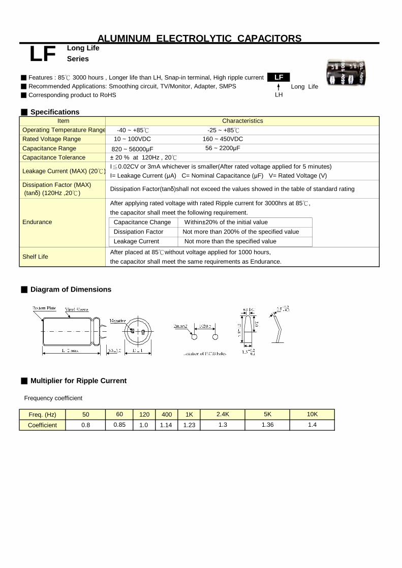
Series
■ Features : 85℃ 3000 hours , Longer life than LH, Snap-in terminal, High ripple current LF■ Recommended Applications: Smoothing circuit, TV/Monitor, Adapter, SMPS Long Life■ Corresponding product to RoHS LH
■ Specifications
Capacitance Range Capacitance Tolerance
I= Leakage Current (μA) C= Nominal Capacitance (μF) V= Rated Voltage (V)
■ Diagram of Dimensions
■ Multiplier for Ripple Current
Frequency coefficient
Freq. (Hz) 50 120 400 1K
Coefficient 0.8 1.0 1.14 1.23
ALUMINUM ELECTROLYTIC CAPACITORSLong Life
Characteristics
LF
Item -40 ~ +85℃
Leakage Current (MAX) (20℃)I≦0.02CV or 3mA whichever is smaller(After rated voltage applied for 5 minutes)± 20 % at 120Hz , 20℃
10 ~ 100VDC820 ~ 56000μF 56 ~ 2200μF
Operating Temperature Range Rated Voltage Range
After applying rated voltage with rated Ripple current for 3000hrs at 85℃,
the capacitor shall meet the same requirements as Endurance.
Not more than 200% of the specified value
Dissipation Factor (MAX) (tanδ) (120Hz ,20℃)
160 ~ 450VDC -25 ~ +85℃
0.85
2.4K
Dissipation Factor(tanδ)shall not exceed the values showed in the table of standard rating
Endurance
Shelf Life
the capacitor shall meet the following requirement. Within±20% of the initial value Capacitance Change
10K
1.4
5K
Leakage Current Dissipation Factor
60
Not more than the specified value
1.3 1.36
After placed at 85℃without voltage applied for 1000 hours,

Series
■Dimensions,Max Dissipation Factor,Max Permissible Ripple Current,Max Equivalent Series Resistance
22x252.45
22x302.60
22x25 22x35 25x252.45 3.10 2.90
22x30 22x40 25x30 30x252.80 3.46 3.30 3.40
22x35 25x25 22x45 25x35 30x303.34 3.15 3.81 3.70 3.85
22x40 25x30 30x25 22x50 25x45 30x30 35x253.67 3.50 3.60 4.32 4.40 4.15 4.23
22x45 25x35 30x30 25x45 30x35 35x304.12 4.00 4.16 4.65 4.65 4.79
22x50 25x40 30x30 35x25 30x40 35x354.63 4.49 4.45 4.54 5.25 5.41
25x45 30x35 35x30 30x45 35x354.90 4.90 5.05 5.86 5.80
25x50 30x40 35x30 35x405.55 5.61 5.50 6.45
30x45 35x356.11 6.05
22x252.10
22x30 25x252.30 2.30
22x25 22x35 25x30 30x25 35x252.20 2.60 2.62 2.70 2.99
22x30 25x25 22x40 25x35 30x30 35x252.45 2.45 2.90 2.93 3.07 3.13
22x35 25x30 22x45 25x35 30x30 35x252.75 2.75 3.30 3.20 3.33 3.42
22x40 25x30 30x25 22x50 25x40 30x30 35x253.25 3.10 3.19 3.74 3.64 3.60 3.67
22x45 25x35 30x30 35x25 25x45 30x35 35x303.50 3.40 3.54 3.64 4.00 4.00 4.12
25x40 30x35 35x30 30x40 35x353.90 4.10 4.21 4.60 4.74
25x45 30x40 35x30 30x45 35x404.30 4.51 4.39 5.10 5.30
30x45 35x35 35x454.90 4.85 5.70
30x50 35x40 35x505.45 5.45 6.45
35x456.15
☆Size:Dψx L(mm). ☆tanδ:20℃,120Hz. ☆Ripple Current: 85℃,120Hz,(A/rms) ☆ESR:20℃,120Hz,(Ω).
Rated (Surge) Voltage
Ripple Current
25(32) 35(44)ψDxL
tanδ
Capacitance (μF)
0.5512000
15000
47000
56000
18000
22000
27000
33000
16(20)
10000
LF
0.089
ALUMINUM ELECTROLYTIC CAPACITORS Long Life
8200
ψDxLRipple Current
tanδ ESR
10(13)
0.55
ψDxLtanδ ESR
Ripple Current
ψDxLtanδ ESR
Ripple Current
18000
4700
5600
6800
8200
3900
0.04015000
27000
ESR
39000
10000
12000
22000
0.049
0.061
0.55 0.073
0.061
0.55
0.55
0.55
0.041
0.55 0.049
0.55
0.55 0.033 0.55
0.55 0.027
0.022
0.55 0.016
0.40
33000
0.136
0.107 0.40 0.095
0.40 0.113
0.45
0.078
0.45 0.073 0.40 0.065
0.45 0.088 0.40
0.45 0.060 0.40
0.400.45 0.050
0.053
0.044
0.40 0.035
0.45 0.033 0.40 0.029
0.45
0.45 0.027 0.40 0.024
0.45 0.022 0.40 0.020
0.45 0.018
0.55 0.016
Rated (Surge) VoltageCapacitance
(μF)
0.55 0.019
0.55 0.027
0.55
0.041
0.55 0.019
0.022
0.033
0.55
0.55 0.013
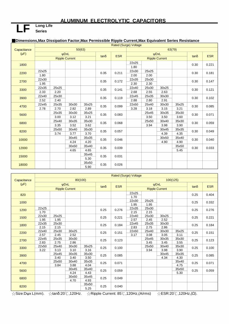
Series
■Dimensions,Max Dissipation Factor,Max Permissible Ripple Current,Max Equivalent Series Resistance
22x251.80
22x25 22x30 25x251.80 2.00 2.00
22x30 22x35 25x301.95 2.30 2.30
22x35 25x25 22x40 25x30 30x252.33 2.20 2.68 2.55 2.63
22x40 25x30 22x45 25x35 30x302.52 2.40 2.88 2.80 2.91
22x45 25x35 30x30 35x25 22x50 25x40 30x30 35x252.78 2.70 2.82 2.89 3.28 3.18 3.15 3.21
25x35 30x30 35x25 25x45 30x35 35x303.00 3.12 3.21 3.50 3.50 3.60
25x40 30x35 35x30 25x50 30x40 35x303.35 3.52 3.62 3.94 3.98 3.90
25x50 30x40 35x30 30x45 35x353.74 3.77 3.70 4.39 4.35
30x45 35x35 30x50 35x404.24 4.20 4.90 4.90
30x50 35x40 35x504.65 4.65 5.45
35x455.30
35x505.90
22x251.70
22x30 25x251.95 1.95
22x25 22x35 25x301.70 2.15 2.15
22x30 25x25 22x40 25x30 30x251.95 1.95 2.57 2.45 2.52
22x35 25x30 22x45 25x35 30x302.15 2.15 2.83 2.75 2.86
22x40 25x30 30x25 22x50 25x40 30x30 35x252.57 2.45 2.52 3.17 3.08 3.05 3.11
22x45 25x35 30x30 25x45 30x35 35x302.83 2.75 2.86 3.45 3.45 3.55
22x50 25x40 30x30 35x25 25x50 30x40 35x303.22 3.13 3.10 3.16 3.94 3.98 3.90
25x45 30x35 35x30 30x45 35x353.40 3.40 3.50 4.34 4.30
25x50 30x40 35x35 35x403.84 3.88 4.04 4.75
30x45 35x40 35x504.24 4.43 5.30
30x50 35x454.70 4.93
35x505.25
☆Size:Dψx L(mm). ☆tanδ:20℃,120Hz. ☆Ripple Current: 85℃,120Hz,(A/rms) ☆ESR:20℃,120Hz,(Ω).
Rated (Surge) Voltage
50(63) 63(79)ψDxL
tanδψDxL
tanδ ESR
ALUMINUM ELECTROLYTIC CAPACITORS
LF Long Life
Ripple Current
1800
2700
0.35 0.211
ESR
0.35 0.026
0.35
0.046
0.30
0.031
0.35 0.039
0.35 0.057
3300
3900
4700
0.30
5600
0.30 0.033
0.35
0.35
0.068
10000
0.049
0.040
6800
0.35
0.071
0.30 0.059
0.083 0.30
0.30 0.102
0.35 0.099 0.30 0.085
0.35 0.119
Ripple Current
12000
0.147
0.35 0.141 0.30 0.121
820
80(100) 100(125)ψDxL
tanδ ESRψDxL
tanδ ESRRipple Current
0.0400.25
0.25 0.049
1000
2700 0.25
0.071
0.25 0.059 0.25 0.059
0.25
1200
0.25 0.071
1500
0.25
0.25 0.100
1800
0.25 0.085 0.085
2200
0.25 0.100
0.25 0.123
0.25
3300
0.184
0.25 0.151 0.25 0.151
0.25
3900
0.276
0.221 0.25 0.221
0.25 0.184
0.25 0.332
4700
0.25
0.25
0.25 0.404
5600
0.276
0.123
0.30
8200
6800
0.30
15000
0.181
0.35 0.172
Rated (Surge) VoltageCapacitance
(μF)
0.30 0.221
Ripple Current
Capacitance (μF)
8200
18000
2200

Series
■Dimensions,Max Dissipation Factor,Max Permissible Ripple Current,Max Equivalent Series Resistance
22x251.10
22x25 22x301.15 1.25
22x30 22x30 25x251.30 1.40 1.40
22x35 25x30 22x35 25x301.59 1.62 1.60 1.60
22x35 25x30 22x40 25x30 30x251.70 1.70 1.89 1.80 1.85
22x40 25x35 30x25 22x45 25x35 30x301.97 1.99 1.95 2.11 2.05 2.13
22x50 25x40 30x30 22x50 25x40 30x30 35x302.32 2.28 2.24 2.34 2.27 2.25 2.45
25x45 30x35 35x30 25x50 30x35 35x302.58 2.57 2.65 2.67 2.55 2.63
25x50 30x40 35x35 30x40 35x352.78 2.80 2.92 2.85 2.93
30x45 35x40 30x50 35x403.03 3.17 3.10 3.10
30x50 35x45 35x453.50 3.67 3.60
35x504.08
22x251.00
22x25 25x25 22x30 25x251.00 1.08 1.15 1.15
22x30 25x25 22x30 25x251.15 1.15 1.30 1.30
22x30 25x25 22x35 25x301.29 1.30 1.45 1.45
22x35 25x30 30x25 22x40 25x35 30x251.45 1.45 1.51 1.62 1.63 1.60
22x40 25x35 30x25 22x45 25x40 30x30 35x251.67 1.68 1.65 1.80 1.84 1.80 1.85
22x45 25x35 30x30 25x40 30x35 35x301.94 1.87 1.96 2.00 2.10 2.20
22x50 25x45 30x35 35x30 25x50 30x40 35x302.14 2.21 2.20 2.27 2.32 2.35 2.30
25x50 30x35 35x30 30x45 35x352.32 2.22 2.30 2.57 2.55
30x45 35x35 30x50 35x402.63 2.60 2.90 2.90
30x50 35x40 35x452.90 2.90 3.25
35x453.11
☆Size:Dψx L(mm). ☆tanδ:20℃,120Hz. ☆Ripple Current: 85℃,120Hz,(A/rms) ☆ESR:20℃,120Hz,(Ω).
0.603
Capacitance (μF)
ESRtanδ
0.166
0.15 0.355
Capacitance (μF)
0.15
Ripple Current Ripple Current
Ripple Current
160(200) 180(225)ψDxL
tanδ ESRψDxL
tanδ ESRRipple Current
ALUMINUM ELECTROLYTIC CAPACITORS
LF Long Life
270
0.15 0.423
470
820
390
330
560
680
1800
0.243
0.199
0.293
1200
0.199
1000
1500
0.293
200(250) 250(300)
0.15 0.355
0.423
0.510
2200
tanδ ESRψDxL
0.905
0.15 0.737 0.15 0.737
0.15
0.15 0.111
0.15 0.090
0.15 0.111
330
270
ψDxL
0.15 0.166
0.15 0.130
0.15 1.110
560
0.15 0.166
0.15
390
0.15 0.292
0.15 0.243
0.15 0.199
0.293
0.15 0.199
680
0.133
470
0.15
0.15 0.243
0.423
0.15 0.355 0.15 0.355
0.603
0.15 0.510 0.15 0.510
0.150.15 0.603
1200
0.15
1000
0.15 0.423 0.15
1500
820
220
180
0.133
0.15 0.603
0.15
0.243
0.510
0.166
0.905
0.150.15
0.15
0.15
0.15 0.15
0.15 0.15
0.15 0.15
0.15 0.15
Rated (Surge) Voltage
Rated (Surge) Voltage
0.737
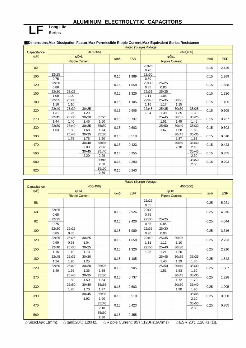
Series
■Dimensions,Max Dissipation Factor,Max Permissible Ripple Current,Max Equivalent Series Resistance
22x250.70
22x25 22x300.75 0.80
22x30 22x30 25x250.80 0.85 0.85
22x30 25x25 22x35 25x251.00 1.00 1.11 1.05
22x35 25x30 22x40 25x35 30x251.10 1.10 1.16 1.17 1.15
22x40 25x30 30x25 22x45 25x35 30x30 35x251.31 1.25 1.29 1.34 1.30 1.35 1.39
22x45 25x35 30x30 35x25 25x45 30x35 35x251.44 1.40 1.46 1.50 1.51 1.49 1.45
22x50 25x40 30x35 35x30 25x50 30x40 35x301.63 1.60 1.68 1.74 1.67 1.68 1.65
25x45 30x35 35x30 30x45 35x351.75 1.75 1.80 1.87 1.85
30x40 35x35 30x50 35x402.00 2.06 2.10 2.10
30x45 35x40 35x452.20 2.29 2.30
35x45 35x502.50 2.60
35x502.80
22x250.65
22x25 22x300.65 0.75
22x25 22x30 25x250.75 0.85 0.85
22x30 25x25 22x35 25x300.85 0.85 0.90 0.90
22x35 25x25 30x25 22x40 25x35 30x250.99 0.93 1.04 1.11 1.12 1.10
22x40 25x30 30x25 22x50 25x40 30x301.15 1.10 1.13 1.25 1.21 1.20
22x45 25x35 30x30 25x45 30x35 35x251.24 1.20 1.25 1.40 1.39 1.35
22x50 25x40 30x30 35x25 25x50 30x40 35x301.40 1.36 1.35 1.38 1.51 1.53 1.50
25x45 30x35 35x30 30x45 35x351.50 1.50 1.54 1.72 1.70
25x50 30x40 35x35 30x50 35x401.70 1.70 1.77 1.90 1.90
30x45 35x35 35x451.92 1.90 2.10
35x40 35x502.10 2.30
35x502.30
☆Size:Dψx L(mm). ☆tanδ:20℃,120Hz. ☆Ripple Current: 85℃,120Hz,(A/rms) ☆ESR:20℃,120Hz,(Ω).
Capacitance (μF)
Capacitance (μF)
120
100
82
315(365)Rated (Surge) Voltage
350(400)
0.243
1.105
ALUMINUM ELECTROLYTIC CAPACITORS
LF Long Life
ψDxLtanδ ESR
Ripple Current Ripple CurrentψDxL
tanδ ESR
0.25 0.705
0.15 0.355
150
0.25 0.850
0.15 0.423
180
220
1.005
0.15 0.510
270
0.25
330
0.15 0.603
390
0.25 1.2280.15 0.737
470
0.25 1.842
0.15 0.905 0.25 1.507
0.15
560
0.25
Ripple Current
0.15
0.25
56
2.763
0.15 1.326 0.25 2.210
3.316
0.15 1.658
1.989 0.25
4.044
tanδ ESR
0.15 2.426
0.25 4.876
tanδ
68
470
82
120
150
180
220
270
100
0.15 2.926
0.15 0.293
0.25 5.921
ESRRipple Current
Rated (Surge) Voltage450(500)
ψDxL
0.423
0.15 0.355 0.15 0.355
0.423 0.15
0.15 0.905
0.15 0.737
0.15 0.603
0.15 0.510
0.603
0.15 0.510
0.15 0.905
0.15 0.737
1.105 0.15 1.105
0.15 1.658
0.15 1.326 0.15 1.326
1.658
0.15 2.426
0.15 1.9891.989
0.15
330
0.15
0.15
0.15
0.15
0.293
560
680
820
400(450)ψDxL
0.15
390
0.15
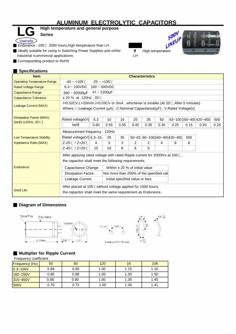
Series
LG■ Ideally suitable for using in Switching Power Supplies and orther High temperature industrial /commercial applications LH■ Corresponding product to RoHS
■ Specifications
Capacitance Range Capacitance Tolerance
Where, I :Leakage Current (μA) ; C:Nominal Capacitance(μF) ; V:Rated Voltage(v)
6.3 10 16 25 35 50 63~100 160~400420~450 5000.60 0.55 0.55 0.45 0.35 0.30 0.25 0.15 0.20 0.25
6.3~16 25 35 50~63 80~100160~400420~450 5004 3 3 2 2 4 8 815 10 8 6 5
■ Diagram of Dimensions
■ Multiplier for Ripple Current Frequency coefficientFrequency (Hz)6.3~100V160~250V315~450V500V
1.001.001.00
1K1.151.301.351.30
500.880.850.880.70
600.900.880.900.72
1.45
47 ~ 2200μF
Rated voltage(V)
Not more than 200% of the specified value
the capacitor shall meet the following requirements.
Measurement frequency : 120Hz
Dissipation Factor
120
-40 ~ +105℃6.3 ~ 100VDC560 ~ 82000μF
160 ~ 500VDC -25 ~ +105℃
Z-25℃ / Z+20℃
Leakage Current
Endurance Capacitance Change
Z-40℃ / Z+20℃
After applying rated voltage with rated Ripple current for 2000hrs at 105℃,
initial specified value or less
1.50
1.41
Shelf Life
Low Temperature Stability
10K1.16
Impedance Ratio (MAX)
After placed at 105℃without voltage applied for 1000 hours,
Within ± 20 % of initial value
the capacitor shall meet the same requirement as Endurance.
1.00
Leakage Current (MAX)I=0.02CV,L=20m/m,I=0.03CV or 3mA , whichever is smaller.(At 20℃,After 5 minutes)± 20 % at 120Hz , 20℃
tanδ
Dissipation Factor (MAX) (tanδ) (120Hz ,20℃)
Rated voltage(V)
Operating Temperature Range Rated Voltage Range
ALUMINUM ELECTROLYTIC CAPACITORS High temperature and general purpose
Characteristics
LG
Item
■ Endurance : 105℃ 2000 hours,high temperature than LHUpgrade

Series
■Dimensions,Rated Ripple Current
Size Ripple Size Ripple Size Ripple Size Ripple4700 22x25 1.50
22x30 1.6525x25 1.65
22x25 1.55 22x30 1.8525x25 1.85
22x30 1.70 22x35 2.1025x25 1.70 25x30 2.10
30x25 2.1525x25 1.55 22x30 1.95 22x40 2.40
25x25 1.95 25x35 2.4030x30 2.4035x25 2.40
22x25 1.55 22x30 1.75 22x35 2.20 22x45 2.7025x30 2.25 25x40 2.7530x25 2.30 30x30 2.70
35x25 2.7522x30 1.70 22x30 1.90 22x40 2.55 25x45 3.1525x25 1.70 25x25 1.90 25x35 2.60 30x35 3.15
30x30 2.60 35x30 3.2535x25 2.65
22x30 1.95 22x35 2.20 22x45 2.90 25x50 3.5525x25 1.95 25x30 2.25 25x40 2.90 30x40 3.55
30x30 2.90 35x35 3.5535x25 2.95
22x35 2.25 22x40 2.50 25x45 3.30 30x45 4.0525x30 2.25 25x35 2.55 30x35 3.30 35x35 3.8030x25 2.25 30x25 2.45 35x30 3.3022x40 2.55 22x50 2.95 25x50 3.80 35x45 4.7025x35 2.55 25x40 2.90 30x40 3.7530x30 2.55 30x30 2.85 35x30 3.7535x25 2.55 35x25 2.8022x45 2.90 25x45 3.30 30x45 4.30 35x50 5.4025x40 2.95 30x35 3.30 35x35 4.2530x30 2.90 35x30 3.3035x25 2.9525x50 3.25 25x50 3.70 30x50 4.80 35x45 5.5030x35 3.25 30x40 3.7 35x40 4.8035x30 3.30 35x30 3.6525x50 3.70 30x45 4.20 35x45 5.45 35x50 6.0030x40 3.70 35x35 3.8030x45 4.15 30x50 4.65 35x45 5.6535x35 4.10 35x40 4.6530x50 4.70 35x50 5.50 35x50 6.2035x40 4.70
82000 35x45 5.30
56000
12000
15000
18000
22000
39000
47000
ALUMINUM ELECTROLYTIC CAPACITORSHigh temperature and general purpose
5600
6800
Rated (Surge) Voltage
LGCapacitance
(μF) 6.3 (8) 10 (13) 16 (20) 25 (32)
☆ Size: Dψx L (mm) ☆ Ripple Current ︰ A/rms. 105℃,120Hz
8200
10000
68000
27000
33000

Series
■Dimensions,Rated Ripple Current
Size Ripple Size Ripple Size Ripple Size Ripple820 22x25 1.10
22x30 1.2025x25 1.20
22x25 1.20 22x30 1.4025x25 1.40
22x30 1.30 22x35 1.6025x25 1.30 25x30 1.60
30x25 1.6522x25 1.30 22x30 1.50 22x40 1.80
25x25 1.50 25x35 1.8530x25 1.80
22x30 1.55 22x35 1.70 22x45 2.0525x25 1.55 25x30 1.75 25x35 2.00
30x25 1.80 30x30 2.0535x25 2.05
22x30 1.70 22x40 2.00 25x45 2.3525x25 1.70 25x35 2.00 30x35 2.35
30x25 1.95 35x30 2.3522x25 1.40 22x35 1.95 22x50 2.30 25x50 2.70
25x30 1.85 25x40 2.30 30x40 2.7030x30 2.25 35x30 2.5535x25 2.10
22x30 1.55 22x40 2.15 25x45 2.55 30x45 3.0025x25 1.55 25x35 2.20 30x35 2.55 35x35 3.00
30x25 1.95 35x30 2.5522x35 1.80 22x45 2.45 25x50 2.85 30x50 3.4025x25 1.80 25x40 2.45 30x40 2.85 35x40 3.40
30x30 2.45 35x30 2.8035x25 2.50
22x35 1.95 22x50 2.75 30x45 3.20 35x45 3.8025x30 1.95 25x40 2.70 35x35 3.2030x25 2.00 30x35 2.75
35x30 2.7522x40 2.20 25x50 3.30 30x50 3.65 35x50 3.9025x35 2.25 30x40 3.30 35x40 3.6530x30 2.30 35x30 3.2535x25 2.3522x50 2.55 30x45 3.60 35x45 3.9025x40 2.50 35x35 3.5530x30 2.7535x25 2.7525x45 2.85 30x50 4.05 35x50 4.4030x35 2.90 35x40 4.0035x30 2.9525x50 3.25 35x45 4.5530x40 3.2535x30 3.1530x45 3.7035x35 3.65
18000 35x40 4.3522000 35x50 4.90
ALUMINUM ELECTROLYTIC CAPACITORSHigh temperature and general purpose
10000
2200
2700
3300
3900
1000
1200
1500
1800
12000
15000
4700
5600
6800
8200
☆ Size: Dψx L (mm) ☆ Ripple Current ︰ A/rms. 105℃,120Hz
LGCapacitance
(μF) 35 (44) 50 (63)Rated (Surge) Voltage
63 (79) 80 (100)

Series
■Dimensions,Rated Ripple Current
Size Ripple Size Ripple Size Ripple Size Ripple150 22x20 0.65180 22x20 0.75 22x20 0.70
22x20 0.80 22x25 0.85 22x25 0.8025x20 0.80
22x25 1.00 22x25 0.95 22x25 0.8525x20 0.90 25x25 0.85
22x25 1.20 22x25 1.20 22x30 1.2025x20 1.15 22x30 1.10 25x25 1.20
25x25 1.1022x30 1.30 22x30 1.30 22x30 1.3025x25 1.30 25x25 1.30 22x35 1.30
25x30 1.3030x25 1.30
22x30 1.30 22x30 1.30 22x35 1.4022x35 1.40 22x35 1.35 22x40 1.4025x25 1.40 25x30 1.40 25x30 1.40
30x25 1.40 30x25 1.5022x25 1.05 22x40 1.50 22x40 1.50 22x45 1.55
25x30 1.50 25x35 1.55 25x35 1.5530x25 1.50 30x25 1.50 30x30 1.55
22x25 1.20 22x45 1.70 22x45 1.70 22x50 1.7525x35 1.70 22x50 1.70 25x40 1.7530x25 1.70 25x35 1.70 30x30 1.75
25x40 1.75 35x25 1.7030x30 1.7035x25 1.70
22x30 1.30 22x50 1.95 22x50 1.95 25x50 2.0525x25 1.33 25x40 2.00 25x40 2.00 30x35 2.00
30x30 2.00 25x45 2.00 35x30 2.0535x25 1.90 30x35 2.00
35x25 1.9022x35 1.50 25x45 2.20 25x45 2.20 30x40 2.3025x30 1.50 30x35 2.20 25x50 2.20 30x45 2.30
35x30 2.20 30x35 2.25 35x30 2.3030x40 2.25 35x35 2.3035x30 2.25
22x40 1.70 25x50 2.45 25x50 2.45 30x50 2.6025x35 1.70 30x40 2.45 30x40 2.45 35x40 2.6530x25 1.70 35x30 2.45 30x45 2.50
35x35 2.5022x45 1.95 30x45 2.80 30x45 2.80 35x45 3.1025x40 2.00 35x35 2.80 30x50 2.9030x30 1.95 35x40 2.9035x25 2.0025x45 2.20 30x50 3.30 30x50 3.30 35x50 3.1530x35 2.50 35x45 3.30 35x50 3.3035x30 2.4525x50 2.55 35x50 3.75 35x50 3.6030x40 2.7035x30 2.5530x45 2.9035x35 2.8530x50 3.2535x40 3.25
3900 35x45 3.704700 35x50 3.80
ALUMINUM ELECTROLYTIC CAPACITORS High temperature and general purpose
3300
680
820
1000
1200
330
390
LG
1500
1800
2200
2700
560
☆ Size: Dψx L (mm) ☆ Ripple Current ︰ A/rms. 105℃,120Hz
Rated (Surge) Voltage100 (125) 160 (200) 180 (225) 200 (250)
470
Capacitance(μF)
220
270

Series
■Dimensions,Rated Ripple Current
Size Ripple Size Ripple Size Ripple Size Ripple Size Ripple47 22x20 0.35 22x25 0.3856 22x20 0.40 22x20 0.40 22x25 0.40
22x25 0.45 22x25 0.50 22x30 0.5025x20 0.50 25x25 0.50
22x25 0.55 22x25 0.52 22x30 0.5225x20 0.50 22x30 0.60 22x35 0.55
25x25 0.65 25x30 0.5530x25 0.55
22x30 0.70 22x30 0.60 22x30 0.5525x25 0.70 22x35 0.65 22x40 0.65
25x30 0.65 25x30 0.6030x25 0.65
22x20 0.60 22x35 0.75 22x30 0.62 22x35 0.6025x30 0.75 22x35 0.70 22x45 0.7030x25 0.75 25x30 0.70 25x35 0.70
30x25 0.75 30x30 0.7035x25 0.70
22x25 0.65 22x40 0.80 22x35 0.72 22x35 0.58 22x40 0.6825x30 0.80 22x40 0.80 22x40 0.65 22x50 0.8030x25 0.85 25x30 0.85 25x30 0.70 25x40 0.80
25x35 0.85 30x30 0.7530x30 0.85 35x25 0.7535x25 0.80
22x25 0.80 22x45 0.90 22x40 0.81 22x40 0.68 22x45 0.7525x20 0.75 25x35 0.90 22x50 0.95 25x35 0.68 25x45 0.85
30x30 0.90 25x40 0.95 30x35 0.8530x30 0.90 35x30 0.85
22x30 0.95 22x50 1.05 25x45 1.05 25x40 0.85 22x50 0.8525x25 0.95 25x40 1.05 30x35 1.05 25x45 0.95 25x50 1.00
30x30 1.00 35x30 1.10 30x40 0.95 30x40 1.0035x25 1.05 35x30 1.00
22x35 1.15 25x45 1.20 25x45 1.10 25x45 1.05 25x50 1.0525x30 1.15 30x35 1.20 25x50 1.20 30x40 1.05 30x45 1.1530x25 1.15 35x30 1.20 30x40 1.20 35x30 1.05 35x35 1.15
35x35 1.2022x40 1.25 30x40 1.35 25x50 1.25 25x50 1.15 30x45 1.2525x30 1.20 35x35 1.35 30x45 1.40 30x40 1.15 30x50 1.4030x25 1.25 35x35 1.35 35x35 1.15 35x40 1.4022x45 1.5 30x45 1.50 30x45 1.42 30x45 1.25 30x50 1.4025x35 1.50 35x35 1.50 30x50 1.55 35x45 1.5530x30 1.50 35x40 1.5522x50 1.55 35x40 1.70 30x45 1.45 30x50 1.40 35x45 1.6825x40 1.55 35x40 1.65 35x40 1.35 35x50 1.7030x30 1.55 30x50 1.7535x25 1.55 35x45 1.7525x45 1.80 35x45 1.90 35x45 1.80 35x45 1.65 35x50 1.8030x35 1.80 30x60 1.90 35x60 2.1035x30 1.80 35x50 1.9025x50 1.95 35x50 2.1030x40 2.00 35x60 2.1535x35 2.0030x45 2.1535x35 2.10
1000 35x40 2.301500 35x50 3.63
ALUMINUM ELECTROLYTIC CAPACITORS
82
100
☆ Size: Dψx L (mm) ☆ Ripple Current ︰ A/rms. 105℃,120Hz
680
470
560
120
150
180
400 (450) 450 (500)
270
68
820
220
330
390
LGCapacitance
(μF)
High temperature and general purpose
Rated (Surge) Voltage420(470)250 (300) 350 (400)

Series
■Dimensions,Rated Ripple CurrentRated (Surge) Voltage
Size Ripple47 22x25 0.5156 22x30 0.5868 25x25 0.65
22x35 0.7225x30 0.7422x45 0.8330x25 0.8222x50 0.9325x35 0.9330x30 0.9125x45 1.0830x35 1.0435x25 0.9925x50 1.2030x40 1.1735x30 1.1030x45 1.3335x35 1.2330x50 1.5035x40 1.42
330 35x45 1.60390 35x50 1.78470 35x60 2.03
220
270
High temperature and general purpose
82
180
☆ Size: Dψx L (mm) ☆ Ripple Current ︰ A/rms. 105℃,120Hz
ALUMINUM ELECTROLYTIC CAPACITORS
100
120
150
Capacitance(μF) 500 (550)
LG

Series
LS■ Ideally suitable for using in Switching Power Supplies and orther Smaller size industrial /commercial applications LG■ Corresponding product to RoHS
■ Specifications
Capacitance Range Capacitance Tolerance
Where, I :Leakage Current (μA) ; C:Nominal Capacitance(μF) ; V:Rated Voltage(v)
■ Diagram of Dimensions
■ Multiplier for Ripple Current Frequency coefficient
Frequency 160~250V315~450V
Operating Temperature Range Rated Voltage Range
ALUMINUM ELECTROLYTIC CAPACITORSHigh temperature and Smaller Size
Characteristics
LS
Item
■ Endurance : 105℃ 2000 hours, smaller size than LG
Leakage Current (MAX) I=0.02CV or 3mA , whichever is smaller.(At 20℃, After 5 minutes)± 20 % at 120Hz , 20℃
tanδ Dissipation Factor (MAX) (tanδ) (120Hz ,20℃)
Rated voltage(V)
After placed at 105℃without voltage applied for 1000 hours,
Within ± 20 % of initial value
the capacitor shall meet the same requirement as Endurance.
Measurement frequency : 120Hz
Dissipation Factor
0.20
160~400
1.501.45
Shelf Life
Low Temperature Stability
10K
Impedance Ratio (MAX) Z-25℃ / Z+20℃
Leakage Current
Endurance Capacitance Change
After applying rated voltage with rated Ripple current for 2000hrs at 105℃,
initial specified value or less
4 8
Not more than 200% of the specified value
the capacitor shall meet the following requirements.
-25 ~ +105℃
420~450
1201.00
Rated voltage(V)
160 ~ 450VDC100 ~ 3300μF
160~4000.15
420~450
1.00
1K1.301.35
500.850.88
600.880.9

Series
■Dimensions,Rated Ripple Current
Size Ripple Size Ripple Size Ripple Size Ripple
330 22x25 1.26
22x30 1.34 22x30 1.08
25x25 1.08
22x30 1.20 22x35 1.48 22x35 1.17
25x30 1.40 25x30 1.30
22x30 1.40 22x35 1.48 22x40 1.45 22x40 1.40
25x30 1.48 25x30 1.45 25x35 1.50
30x25 1.26
22x35 1.50 22x40 1.60 22x40 1.49 22x45 1.35
25x30 1.70 25x35 1.60 25x35 1.78 25x40 1.70
30x30 1.65 30x30 1.70
22x40 2.00 22x45 1.75 22x50 1.93
25x35 2.00 25x40 1.75 25x40 1.93 25x45 2.00
30x30 1.75 30x30 1.85 30x35 2.00
35x25 1.93 35x30 2.00
22x50 2.10 25x45 2.15
25x40 2.20 25x45 2.04 30x35 2.33 25x50 2.20
30x30 2.20 30x35 2.04 35x30 2.33 30x40 2.20
35x30 2.00
25x45 2.30 25x50 2.30
30x35 2.30 30x40 2.30 30x40 2.50 30x45 2.30
35x30 2.30 35x30 2.12 35x35 2.20
25x50 2.50
30x40 2.50 30x45 2.57 30x45 2.30
35x30 2.50 35x35 2.57 35x35 2.25 35x40 2.30
30x45 2.70 30x50 2.41
35x35 2.55 35x40 2.68 35x40 2.43 35x50 2.50
30x50 2.90
35x45 2.90 35x45 2.63 35x50 2.95
2700 35x50 3.00 35x55 3.27
3300 35x60 3.10
☆ Size: Dψx L (mm) ☆ Ripple Current ︰ A/rms. 105℃,120Hz
Rated (Surge) Voltage160 (200) 200 (250) 220 (270) 250(300)Capacitance
(μF)
1800
2200
1200
1500
390
820
680
1000
470
560
High temperature and Smaller-sizeLSALUMINUM ELECTROLYTIC CAPACITORS

Series
■Dimensions,Rated Ripple Current
Size Ripple Size Ripple Size Ripple
100 22x25 0.50
120 22x25 0.61 22x25 0.46 22x30 0.60
22x30 0.54 22x35 0.72
25x25 0.65 25x25 0.73
22x30 0.68 22x35 0.64 22x40 0.79
25x25 0.66 25x30 0.64 25x30 0.71
22x35 0.80 22x40 0.80 22x45 0.87
25x30 0.77 25x35 0.80 25x35 0.78
30x25 0.80 30x25 0.83
22x40 0.95 22x50 1.00 22x50 0.95
25x35 1.00 25x40 1.00 25x40 0.90
30x25 0.93 30x30 1.00 30x35 1.05
35x25 0.95
22x50 1.04 25x45 1.10 25x50 1.20
25x40 1.04 30x35 1.10 30x35 1.14
30x30 1.08 35x30 1.10 35x30 1.20
35x25 1.04
25x45 1.26 25x50 1.20 30x40 1.31
30x35 1.26 30x40 1.20 35x35 1.38
35x30 1.55 35x30 1.20
30x40 1.40 30x45 1.30 30x45 1.48
35x30 1.46 35x35 1.30 35x35 1.47
30x45 1.56 30x50 1.60 35x40 1.62
35x35 1.54 35x40 1.60
30x50 1.72 35x45 2.00 35x50 1.91
35x40 1.70
35x45 1.91 35x50 2.30
Rated (Surge) Voltage
330
820
400 (450) 450 (500)
180
LS
Capacitance(μF)
High temperature and Smaller-size
420(470)
150
ALUMINUM ELECTROLYTIC CAPACITORS
☆ Size: Dψx L (mm) ☆ Ripple Current ︰ A/rms. 105℃,120Hz
220
560
680
270
470
390

Series
■ Features : 105℃ 3000 hours , Wide temperature range for LF , Longer life than LG, LJ Snap-in terminal, High ripple current Long Life■ Recommended Applications: Smoothing circuit, TV/Monitor,Adapter, SMPS LG■ Corresponding product to RoHS
■ Specifications
Capacitance Range Capacitance Tolerance
I= Leakage Current (μA) C= Nominal Capacitance (μF) V= Rated Voltage (V)
After applying rated voltage with rated Ripple current for 3000hrs at 105℃,
■ Diagram of Dimensions
■ Multiplier for Ripple Current
Frequency coefficient
Freq. (Hz) 50 120 400 1K
10~450V 0.80 1.00 1.14 1.23
500V 0.70 1.00 1.16 1.30
0.85 1.30 1.36 1.40
0.72 1.32 1.36 1.41
Shelf Life
the capacitor shall meet the following requirement.
After placed at 105℃without voltage applied for 1000 hours,
Dissipation Factor
the capacitor shall meet the same requirements as Endurance.
56 ~ 2200μF10 ~ 100VDC
560 ~ 68000μF
Endurance Capacitance Change Within±20% of the initial value Not more than 200% of the specified value Not more than the specified value
Leakage Current (MAX) (20℃)I≦0.02CV or 3mA whichever is smaller(After rated voltage applied for 5 minutes)
160 ~ 500VDC -25 ~ +105℃
± 20 % at 120Hz , 20℃
Dissipation Factor (MAX) (tanδ) (120Hz ,20℃) Dissipation Factor(tanδ)shall not exceed the values showed in the table of standard rating
10K5K2.4K60
Leakage Current
Operating Temperature Range Rated Voltage Range
ALUMINUM ELECTROLYTIC CAPACITORSHigh temperature and long life
Characteristics
LJ
Item -40 ~ +105℃
Upgrade

Series
■Dimensions,Max Dissipation Factor,Max Permissible Ripple Current,Max Equivalent Series Resistance
22x251.80
22x30 25x252.05 2.05
22x25 22x35 25x301.80 2.45 2.45
22x30 25x25 22x40 25x30 30x252.05 2.05 2.73 2.60 2.68
22x35 25x30 30x25 22x45 25x35 30x302.45 2.45 2.55 2.99 2.90 3.02
22x40 25x30 30x30 22x50 25x40 30x30 35x252.94 2.80 3.11 3.43 3.33 3.30 3.37
22x45 25x35 30x30 35x25 25x45 30x35 35x303.24 3.15 3.28 3.37 3.70 3.70 3.81
25x40 30x35 35x30 30x40 35x353.5 3.67 3.78 4.15 4.27
25x45 30x40 35x30 30x50 35x404.00 4.20 4.08 4.65 4.65
25x50 30x45 35x35 35x454.45 4.67 4.63 5.25
35x40 35x504.90 5.80
35x455.50
35x506.05
22x251.45
22x301.60
22x25 22x301.50 1.80
22x30 22x35 25x251.80 2.23 2.10
22x30 25x25 22x40 25x30 30x251.95 1.95 2.41 2.30 2.37
22x35 25x30 22x45 25x35 30x302.20 2.20 2.68 2.60 2.70
22x40 25x35 30x25 22x50 25x40 30x30 35x252.47 2.50 2.45 3.02 2.93 2.90 2.96
22x45 25x40 30x30 25x45 30x35 35x302.75 2.80 2.75 3.20 3.20 3.30
22x50 25x45 30x35 35x25 25x50 30x40 35x303.13 3.22 3.19 3.10 3.64 3.67 3.6
25x50 30x40 35x30 30x45 35x353.43 3.47 3.40 4.04 4.00
30x45 35x35 35x403.94 3.90 4.60
30x50 35x40 35x504.30 4.30 5.10
35x454.85
☆Size:Dψx L(mm). ☆tanδ:20℃,120Hz. ☆Ripple Current: 105℃,120Hz,(A/rms) ☆ESR:20℃,120Hz,(Ω).
tanδ ESR
33000
Capacitance (μF)
0.55 0.016
56000
68000
39000
0.024
0.55 0.016
0.55
0.55
0.55 0.019
0.55 0.027
0.044
0.40 0.0531
0.078
0.033
0.55 0.027
0.55 0.019
0.022
0.40
0.40
0.40 0.029
0.40 0.035
0.40
0.40
0.40
0.45
0.45 0.040
0.45 0.033
0.40
0.050
0.060
0.45 0.027
0.45 0.073
0.45
0.065
0.45 0.107 0.095
0.45 0.088
0.400.45
27000
6800
22000
15000
18000
10000
12000
8200
5600
0.022 0.55
0.550.55 0.033
0.55 0.049
0.061
0.041
0.55 0.049
0.041 0.55
0.55 0.55
3300
0.013
Ripple Current
3900
4700 0.127
2700
0.153
0.089
ψDxL
Rated (Surge) Voltage
0.45
0.196
Ripple CurrentψDxL
25(32) 35(44)
0.0730.55
0.55
10(13)
0.55
0.55
Ripple Current
ALUMINUM ELECTROLYTIC CAPACITORSHigh temperature and long life
6800
ψDxLRipple Current
tanδ ESR
47000
18000
22000
27000
LJCapacitance
(μF)
8200
15000
Rated (Surge) Voltage
0.55
0.107
ψDxLtanδ ESR
10000
12000
0.073
0.061
0.55 0.011
16(20)
tanδ ESR
0.136
0.161
0.113
0.40
0.40
0.45 0.022

Series
■Dimensions,Max Dissipation Factor,Max Permissible Ripple Current,Max Equivalent Series Resistance
22x251.25
22x25 22x30 25x251.25 1.45 1.45
22x30 22x35 25x301.45 1.6 1.6
22x30 25x25 22x40 25x30 30x251.6 1.6 1.89 1.8 1.85
22x35 25x30 22x45 25x35 30x301.8 1.8 2.06 2 2.08
22x40 25x30 30x25 25x40 30x30 35x252.05 1.95 2.01 2.32 2.3 2.35
22x45 25x35 30x30 25x45 30x35 35x302.27 2.2 2.29 2.55 2.55 2.63
22x50 25x40 30x30 35x25 25x50 30x40 35x302.5 2.42 2.4 2.45 2.83 2.86 2.8
25x45 30x35 35x30 30x45 35x352.7 2.7 2.78 3.18 3.15
30x40 35x30 30x50 35x403.06 3 3.5 3.5
30x45 35x35 35x453.38 3.35 3.9
35x403.7
35x504.20
22x251.20
22x301.35
22x25 22x30 25x251.20 1.50 1.50
22x30 22x35 25x301.35 1.70 1.70
22x35 25x25 22x40 25x35 30x251.59 1.50 1.97 1.99 1.95
22x40 25x30 30x25 22x45 25x40 30x30 35x251.78 1.70 1.75 2.15 2.19 2.15 2.21
22x45 25x35 30x30 25x45 30x35 35x302.01 1.95 2.03 2.45 2.45 2.52
25x40 30x30 35x25 25x50 30x40 35x352.17 2.15 2.19 2.75 2.75 2.86
25x45 30x35 35x30 30x45 35x352.45 2.45 2.52 3.08 3.05
30x40 35x35 30x50 35x402.75 2.83 3.45 3.45
30x45 35x35 35x453.13 3.10 3.90
35x40 35x503.40 4.30
35x503.80
☆Size:Dψx L(mm). ☆tanδ:20℃,120Hz. ☆Ripple Current: 105℃,120Hz,(A/rms) ☆ESR:20℃,120Hz,(Ω).
0.071
0.25 0.059
0.085
0.071 0.250.25
0.25 0.085 0.25
12000
3900
3300
2700
1800
2200
2700
3300
3900
1500
1200 0.30 0.332
0.30 0.265
0.35 0.258 0.30 0.221
0.35 0.211 0.30 0.181
0.35 0.172
5600
4700
10000
6800
5600
Capacitance (μF)
0.30 0.147
0.30 0.121
0.35 0.119
0.35
0.102
0.35 0.099 0.30 0.085
0.30
0.35 0.083
0.141
0.30 0.071
2200
0.35 0.068 0.30 0.059
1200
0.30 0.049
0.35 0.046
1500
0.35 0.057
820
1000
Ripple CurrentESR
ψDxLtanδ
0.25 0.488
Ripple CurrentψDxL
0.25
0.35 0.039
0.25
560
680
0.404 0.25
0.3320.25 0.25
0.25 0.184
0.25 0.276
0.2210.25
0.25 0.100
0.25 0.151
0.25 0.1230.25 0.123
0.25 0.184
0.25 0.276
0.25 0.221
4700
80(100)
8200
Rated (Surge) Voltage100(125)
0.309
tanδ ESRRipple Current Ripple Current
ESRψDxL
0.35
ALUMINUM ELECTROLYTIC CAPACITORS
LJ High temperature and long life
Rated (Surge) VoltageCapacitance
(μF)50(63) 63(79)
ψDxLtanδ
0.592
tanδ ESR
1800
0.404
0.332
0.25 0.151
0.25 0.100
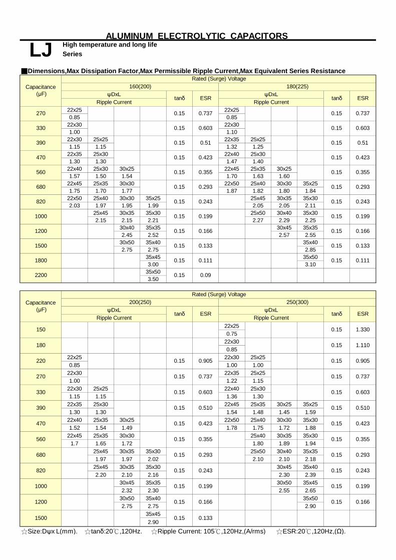
■Dimensions,Max Dissipation Factor,Max Permissible Ripple Current,Max Equivalent Series Resistance
22x25 22x250.85 0.85
22x30 22x301.00 1.10
22x30 25x25 22x35 25x251.15 1.15 1.32 1.25
22x35 25x30 22x40 25x301.30 1.30 1.47 1.40
22x40 25x30 30x25 22x45 25x35 30x251.57 1.50 1.54 1.70 1.63 1.60
22x45 25x35 30x30 22x50 25x40 30x30 35x251.75 1.70 1.77 1.87 1.82 1.80 1.84
22x50 25x40 30x30 35x25 25x45 30x35 35x302.03 1.97 1.95 1.99 2.05 2.05 2.11
25x45 30x35 35x30 25x50 30x40 35x302.15 2.15 2.21 2.27 2.29 2.25
30x40 35x35 30x45 35x352.45 2.52 2.57 2.55
30x50 35x40 35x402.75 2.75 2.85
35x45 35x503.00 3.10
35x503.50
22x250.75
22x300.85
22x25 22x30 25x250.85 1.00 1.00
22x30 22x35 25x251.00 1.22 1.15
22x30 25x25 22x40 25x301.15 1.15 1.36 1.30
22x35 25x30 22x45 25x35 30x25 35x251.30 1.30 1.54 1.48 1.45 1.59
22x40 25x35 30x25 22x50 25x40 30x30 35x301.52 1.54 1.49 1.78 1.75 1.72 1.88
22x45 25x35 30x30 25x40 30x35 35x301.7 1.65 1.72 1.80 1.89 1.94
25x45 30x35 35x30 25x50 30x40 35x351.97 1.97 2.02 2.10 2.10 2.18
25x45 30x35 35x30 30x45 35x402.20 2.10 2.16 2.30 2.39
30x45 35x35 30x50 35x452.32 2.30 2.55 2.65
30x50 35x40 35x502.75 2.75 2.90
35x452.90
☆Size:Dψx L(mm). ☆tanδ:20℃,120Hz. ☆Ripple Current: 105℃,120Hz,(A/rms) ☆ESR:20℃,120Hz,(Ω).
0.1660.15
0.15
0.150.199
1500 0.1330.15
Capacitance (μF)
Capacitance (μF)
0.15
0.133
1200 0.15 0.166
0.15
0.243
1200
Ripple Current
0.150.15
180
0.15
0.15
0.15
0.150.293
0.603
470
0.15
0.15
0.15
390
0.15 0.737
0.603
0.423
0.166
0.199
0.15
0.15 0.243
270 0.737
1000
150
220
0.510
560
470 0.423
820
0.15
0.15
680
390
0.51
0.15 0.355
0.15 0.51
0.423
0.15
0.15
0.15
0.15
0.09
200(250) 250(300)
0.603
0.737
0.15 0.9050.15 0.905
tanδ ESRRipple Current
0.15
1.1100.15
0.423
0.15 0.15
0.15
0.510
0.15
2200
tanδ
0.15
ψDxL ψDxL
0.15 0.111
330
ESR
1800
0.199
560
680
0.293
0.243
1500
0.355
ALUMINUM ELECTROLYTIC CAPACITORS
LJ High temperature and long lifeSeries
270
330
820
1000
0.293
0.2430.15
0.150.15 0.293
Rated (Surge) Voltage
Rated (Surge) Voltage
160(200) 180(225)ψDxL
tanδ ESRψDxL
Ripple Current Ripple Currenttanδ ESR
0.15 0.199
0.15 0.355
0.737
0.6030.15
0.15
0.166
0.355
1.330
0.15 0.133
0.15 0.111
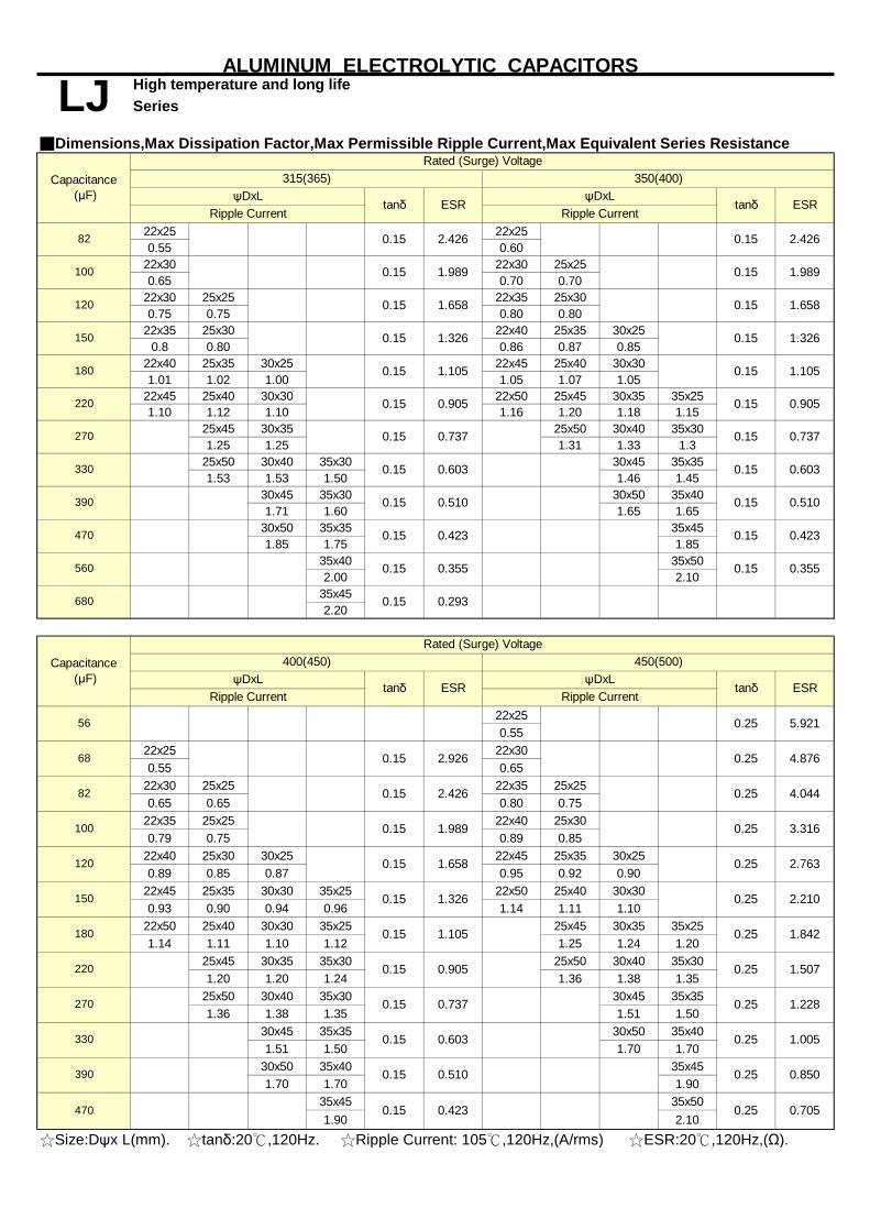
Series
■Dimensions,Max Dissipation Factor,Max Permissible Ripple Current,Max Equivalent Series Resistance
22x25 22x250.55 0.60
22x30 22x30 25x250.65 0.70 0.70
22x30 25x25 22x35 25x300.75 0.75 0.80 0.80
22x35 25x30 22x40 25x35 30x250.8 0.80 0.86 0.87 0.85
22x40 25x35 30x25 22x45 25x40 30x301.01 1.02 1.00 1.05 1.07 1.05
22x45 25x40 30x30 22x50 25x45 30x35 35x251.10 1.12 1.10 1.16 1.20 1.18 1.15
25x45 30x35 25x50 30x40 35x301.25 1.25 1.31 1.33 1.3
25x50 30x40 35x30 30x45 35x351.53 1.53 1.50 1.46 1.45
30x45 35x30 30x50 35x401.71 1.60 1.65 1.65
30x50 35x35 35x451.85 1.75 1.85
35x40 35x502.00 2.10
35x452.20
22x250.55
22x25 22x300.55 0.65
22x30 25x25 22x35 25x250.65 0.65 0.80 0.75
22x35 25x25 22x40 25x300.79 0.75 0.89 0.85
22x40 25x30 30x25 22x45 25x35 30x250.89 0.85 0.87 0.95 0.92 0.90
22x45 25x35 30x30 35x25 22x50 25x40 30x300.93 0.90 0.94 0.96 1.14 1.11 1.10
22x50 25x40 30x30 35x25 25x45 30x35 35x251.14 1.11 1.10 1.12 1.25 1.24 1.20
25x45 30x35 35x30 25x50 30x40 35x301.20 1.20 1.24 1.36 1.38 1.35
25x50 30x40 35x30 30x45 35x351.36 1.38 1.35 1.51 1.50
30x45 35x35 30x50 35x401.51 1.50 1.70 1.70
30x50 35x40 35x451.70 1.70 1.90
35x45 35x501.90 2.10
☆Size:Dψx L(mm). ☆tanδ:20℃,120Hz. ☆Ripple Current: 105℃,120Hz,(A/rms) ☆ESR:20℃,120Hz,(Ω).
ALUMINUM ELECTROLYTIC CAPACITORS
LJ High temperature and long life
Rated (Surge) Voltage
ψDxLtanδ ESR
ψDxLtanδ
0.7050.25
Capacitance (μF)
Ripple CurrentESR
Ripple Current
Capacitance (μF)
82
315(365) 350(400)
0.15 2.426
0.15
0.15 2.426
0.15120 0.15
1.9890.15 1.989100
1.658
150 0.15 1.326 0.15 1.326
1.658
1.105
220 0.15 0.905 0.15 0.905
180
270
0.150.15 1.105
0.15 0.737
390
0.15 0.737
330 0.15 0.603 0.15 0.603
0.423470 0.15
0.510
0.15
0.15
0.355
680 0.15 0.293
0.423
560 0.15 0.355
450(500)ψDxL
tanδ ESRψDxL
tanδ ESRRipple Current Ripple Current
400(450)
0.15 0.423
68
56
82
0.15 0.510
0.603 1.005
0.25 0.850
0.25
1.228
2.210
0.15
220 0.15
270 0.15 0.737 0.25
0.25
0.15 1.105 0.25
1.507
150
100
180
0.15 1.326
120
0.25
0.25 3.316
0.15 1.658 0.25 2.763
1.842
4.876
0.15 2.426 0.25 4.044
390
0.25
330
0.15 1.989
470
0.25 5.921
0.15 2.926
Rated (Surge) Voltage
0.15 0.510
0.15
0.905

Series
■Dimensions,Max Dissipation Factor,Max Permissible Ripple Current,Max Equivalent Series ResistanceRated (Surge) Voltage
22x250.51
22x300.58
25x250.65
22x35 25x300.72 0.74
22x45 30x250.83 0.82
22x50 25x35 30x300.93 0.93 0.91
25x45 30x35 35x251.08 1.04 0.99
25x50 30x40 35x301.20 1.17 1.10
30x45 35x351.33 1.23
30x50 35x401.50 1.42
35x451.60
35x501.78
35x602.03
☆Size:Dψx L(mm). ☆tanδ:20℃,120Hz. ☆Ripple Current: 105℃,120Hz,(A/rms) ☆ESR:20℃,120Hz,(Ω).
120
100
68
470
390 0.25
0.25
0.25 0.705
0.850
1.005
270 0.25 1.228
330
150
0.25 1.507
180 0.25 1.842
220
0.25 2.763
4.044
3.316
0.25 2.210
0.25
82 0.25
ESRRipple Current
0.25 7.055
5.912
0.25 4.876
47
ALUMINUM ELECTROLYTIC CAPACITORS
LJ High temperature and long life
Capacitance (μF)
500(550)ψDxL
tanδ
56 0.25
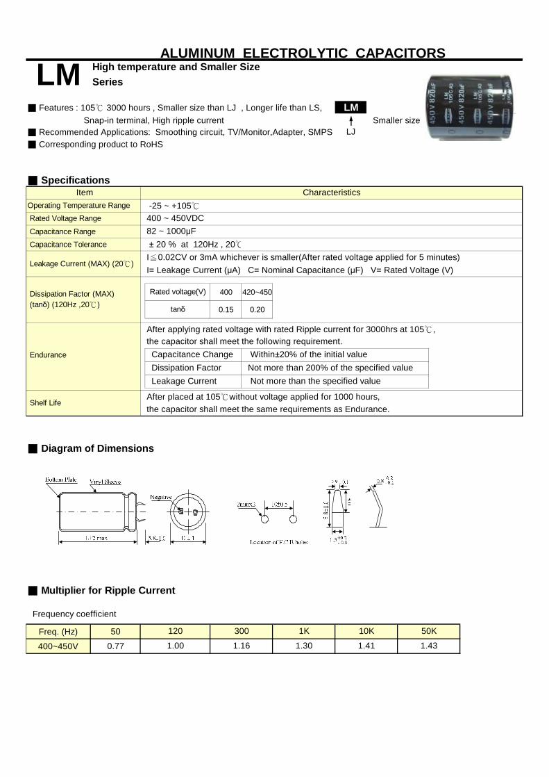
Series
■ Features : 105℃ 3000 hours , Smaller size than LJ , Longer life than LS, LM Snap-in terminal, High ripple current■ Recommended Applications: Smoothing circuit, TV/Monitor,Adapter, SMPS LJ■ Corresponding product to RoHS
■ Specifications
Capacitance Range Capacitance Tolerance
I= Leakage Current (μA) C= Nominal Capacitance (μF) V= Rated Voltage (V)
400 420~450
0.15 0.20
After applying rated voltage with rated Ripple current for 3000hrs at 105℃,
■ Diagram of Dimensions
■ Multiplier for Ripple Current
Frequency coefficient
Freq. (Hz) 50
400~450V 0.77
Operating Temperature Range Rated Voltage Range
ALUMINUM ELECTROLYTIC CAPACITORSHigh temperature and Smaller Size
Characteristics
LM
Item
Smaller size
Leakage Current (MAX) (20℃)I≦0.02CV or 3mA whichever is smaller(After rated voltage applied for 5 minutes) ± 20 % at 120Hz , 20℃
Dissipation Factor (MAX) (tanδ) (120Hz ,20℃)
Rated voltage(V)
tanδ
-25 ~ +105℃
1K
Dissipation Factor
the capacitor shall meet the same requirements as Endurance.
400 ~ 450VDC82 ~ 1000μF
50K
Leakage Current
Endurance Capacitance Change
Shelf Life
the capacitor shall meet the following requirement.
After placed at 105℃without voltage applied for 1000 hours,
Within±20% of the initial value Not more than 200% of the specified value Not more than the specified value
120 300
1.00 1.30 1.41 1.431.16
10K
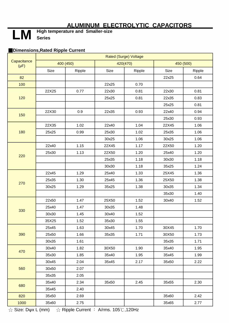
Series
■Dimensions,Rated Ripple Current
Size Ripple Size Ripple Size Ripple
82 22x25 0.64
100 22x25 0.70
22X25 0.77 22x30 0.81 22x30 0.81
25x25 0.81 22x35 0.83
25x25 0.81
22X30 0.9 22x35 0.93 22x40 0.94
25x30 0.93
22X35 1.02 22x40 1.04 22X45 1.06
25x25 0.99 25x30 1.02 25x35 1.06
30x25 1.06 30x25 1.06
22x40 1.15 22X45 1.17 22X50 1.20
25x30 1.13 22X50 1.20 25x40 1.20
25x35 1.18 30x30 1.18
30x30 1.18 35x25 1.24
22x45 1.29 25x40 1.33 25X45 1.36
25x35 1.30 25x45 1.36 25X50 1.38
30x25 1.29 35x25 1.38 30x35 1.34
35x30 1.40
22x50 1.47 25X50 1.52 30x40 1.52
25x40 1.47 30x35 1.48
30x30 1.45 30x40 1.52
35X25 1.52 35x30 1.55
25x45 1.63 30x45 1.70 30X45 1.70
25x50 1.66 35x35 1.71 30X50 1.73
30x35 1.61 35x35 1.71
30x40 1.82 30X50 1.90 35x40 1.95
35x30 1.85 35x40 1.95 35x45 1.99
30x45 2.04 35x45 2.17 35x50 2.22
30x50 2.07
35x35 2.05
35x40 2.34 35x50 2.45 35x55 2.30
35x45 2.40
820 35x50 2.69 35x60 2.42
1000 35x60 2.75 35x65 2.77
680
☆ Size: Dψx L (mm) ☆ Ripple Current ︰ A/rms. 105℃,120Hz
120
150
270
330
Capacitance(μF)
560
180
420(470) 450 (500)
Rated (Surge) Voltage
400 (450)
390
470
ALUMINUM ELECTROLYTIC CAPACITORS
LM High temperature and Smaller-size
220

Series
■ Features : 105℃ 5000 hours , Wide temperature range for LF , Longer life than HW, LQ Snap-in terminal, High ripple current■ Recommended Applications: Smoothing circuit, TV/Monitor,Adapter, SMPS LJ■ Corresponding product to RoHS
■ Specifications
Capacitance Range Capacitance Tolerance
I= Leakage Current (μA) C = Nominal Capacitance (μF) V= Rated Voltage (V)
After applying rated voltage with rated Ripple current for 5000hrs at 105℃,
■ Diagram of Dimensions
■ Multiplier for Ripple Current
Frequency coefficient
Freq. (Hz) 50 120 400 1K
160~450V 0.80 1.00 1.14 1.23
500V 0.70 1.00 1.16 1.30
Leakage Current (MAX) (20℃)
Dissipation Factor (MAX) (tanδ) (120Hz ,20℃)
± 20 % at 120Hz , 20℃
Operating Temperature Range Rated Voltage Range
High temperature and long life
Characteristics
LQ
Item
Long Life
60 2.4K
Dissipation Factor
the capacitor shall meet the same requirements as Endurance.
10K
Not more than 200% of the specified value Not more than the specified value
56 ~ 2200μF
Leakage Current
After placed at 105℃without voltage applied for 1000 hours,
I≦0.02CV or 3mA whichever is smaller(After rated voltage applied for 5 minutes)
Within±20% of the initial value
Dissipation Factor(tanδ)shall not exceed the values showed in the table of standard rating
Endurance Capacitance Change
Shelf Life
the capacitor shall meet the following requirement.
160 ~ 500VDC -25 ~ +105℃
0.85 1.30 1.36 1.40
ALUMINUM ELECTROLYTIC CAPACITORS
1.410.72 1.36
5K
1.32
Upgrade

■Dimensions,Max Dissipation Factor,Max Permissible Ripple Current,Max Equivalent Series Resistance
22x25 22x250.85 0.85
22x30 22x301.00 1.10
22x30 25x25 22x35 25x251.15 1.15 1.32 1.25
22x35 25x30 22x40 25x301.30 1.30 1.47 1.40
22x40 25x30 30x25 22x45 25x35 30x251.57 1.50 1.54 1.70 1.63 1.60
22x45 25x35 30x30 22x50 25x40 30x30 35x251.75 1.70 1.77 1.87 1.82 1.80 1.84
22x50 25x40 30x30 35x25 25x45 30x35 35x302.03 1.97 1.95 1.99 2.05 2.05 2.11
25x45 30x35 35x30 25x50 30x40 35x302.15 2.15 2.21 2.27 2.29 2.25
30x40 35x35 30x45 35x352.45 2.52 2.57 2.55
30x50 35x40 35x402.75 2.75 2.85
35x45 35x503.00 3.10
35x503.50
22x250.75
22x300.85
22x25 22x30 25x250.85 1.00 1.00
22x30 22x35 25x251.00 1.22 1.15
22x30 25x25 22x40 25x301.15 1.15 1.36 1.30
22x35 25x30 22x45 25x35 30x25 35x251.30 1.30 1.54 1.48 1.45 1.59
22x40 25x35 30x25 22x50 25x40 30x30 35x301.52 1.54 1.49 1.78 1.75 1.72 1.88
22x45 25x35 30x30 25x40 30x35 35x301.7 1.65 1.72 1.80 1.89 1.94
25x45 30x35 35x30 25x50 30x40 35x351.97 1.97 2.02 2.10 2.10 2.18
25x45 30x35 35x30 30x45 35x402.20 2.10 2.16 2.30 2.39
30x45 35x35 30x50 35x452.32 2.30 2.55 2.65
30x50 35x40 35x502.75 2.75 2.90
35x452.90
☆Size:Dψx L(mm). ☆tanδ:20℃,120Hz. ☆Ripple Current: 105℃,120Hz,(A/rms) ☆ESR:20℃,120Hz,(Ω).
0.15 0.111
0.15 0.166
ESRψDxL
tanδ ESR
0.15 0.199
0.293
0.15 0.243
0.15
ALUMINUM ELECTROLYTIC CAPACITORS
LQ High temperature and long lifeSeries
Rated (Surge) Voltage
Rated (Surge) Voltage
160(200) 180(225)ψDxL
tanδ
820
1000
Ripple Current Ripple Current
270
330
0.199
560
680
0.293
0.243
0.355
1800
1500
0.355
0.15 0.111
330
0.905
0.423
0.15 0.15
0.15
0.510
0.15 0.603
0.15 0.09
0.15 0.737
0.15 1.110
0.15
2200
tanδ ESRψDxL
0.15
tanδ
0.15 0.905
ESR
0.15 0.133
Ripple Current
1.330
250(300)
0.510
0.15
0.15 0.603
0.15
0.15 0.166
200(250)ψDxL
0.423
0.15 0.355 0.15 0.355
0.603
0.15 0.51 0.15 0.51
0.737
0.15 0.603 0.15
0.15
820
0.15 0.423 0.15
1000
0.15 0.293
0.15 0.243
390
270
220
470
390
0.15 0.737
0.737
680
560
470 0.15 0.423
180
150
1200
Ripple Current
0.15
0.15 0.150.293
0.15
0.15
0.15 0.15
0.15
0.199
0.243
0.15 0.199
0.133
1200 0.15 0.166
1500 0.1330.15
Capacitance (μF)
Capacitance (μF)
0.1660.15

Series
■Dimensions,Max Dissipation Factor,Max Permissible Ripple Current,Max Equivalent Series Resistance
22x25 22x250.55 0.60
22x30 22x30 25x250.65 0.70 0.70
22x30 25x25 22x35 25x300.75 0.75 0.80 0.80
22x35 25x30 22x40 25x35 30x250.8 0.80 0.86 0.87 0.85
22x40 25x35 30x25 22x45 25x40 30x301.01 1.02 1.00 1.05 1.07 1.05
22x45 25x40 30x30 22x50 25x45 30x35 35x251.10 1.12 1.10 1.16 1.20 1.18 1.15
25x45 30x35 25x50 30x40 35x301.25 1.25 1.31 1.33 1.3
25x50 30x40 35x30 30x45 35x351.53 1.53 1.50 1.46 1.45
30x45 35x30 30x50 35x401.71 1.60 1.65 1.65
30x50 35x35 35x451.85 1.75 1.85
35x40 35x502.00 2.10
35x452.20
22x250.55
22x25 22x300.55 0.65
22x30 25x25 22x35 25x250.65 0.65 0.80 0.75
22x35 25x25 22x40 25x300.79 0.75 0.89 0.85
22x40 25x30 30x25 22x45 25x35 30x250.89 0.85 0.87 0.95 0.92 0.90
22x45 25x35 30x30 35x25 22x50 25x40 30x300.93 0.90 0.94 0.96 1.14 1.11 1.10
22x50 25x40 30x30 35x25 25x45 30x35 35x251.14 1.11 1.10 1.12 1.25 1.24 1.20
25x45 30x35 35x30 25x50 30x40 35x301.20 1.20 1.24 1.36 1.38 1.35
25x50 30x40 35x30 30x45 35x351.36 1.38 1.35 1.51 1.50
30x45 35x35 30x50 35x401.51 1.50 1.70 1.70
30x50 35x40 35x451.70 1.70 1.90
35x45 35x501.90 2.10
☆Size:Dψx L(mm). ☆tanδ:20℃,120Hz. ☆Ripple Current: 105℃,120Hz,(A/rms) ☆ESR:20℃,120Hz,(Ω).
0.905
Rated (Surge) Voltage
0.15 0.510
0.15
470
0.25 5.921
0.15 2.926
390
0.25
330
0.15 1.989
4.876
0.15 2.426 0.25 4.044
3.316
0.15 1.658 0.25 2.763
150
100
180
0.25
0.25
0.25
0.15 1.105 0.25 1.842
0.15 1.326
1.507
120
0.15 0.737 0.25 1.228
2.210
0.15
220 0.15
270
1.005
0.25 0.850
0.25
0.15 0.423
68
56
82
0.15 0.510
0.603
450(500)ψDxL
tanδ ESRψDxL
tanδ ESRRipple Current Ripple Current
400(450)
680 0.15 0.293
0.423
560 0.15 0.355
0.510
0.15
0.15
0.355
0.603
0.423470 0.15
0.737
390
0.15 0.737
330 0.15 0.603 0.15
180
270
0.150.15 1.105
0.15
0.15 1.326
1.658
1.105
220 0.15 0.905 0.15 0.905
150 0.15 1.326
0.15120 0.15 1.658
100 0.15 1.989 1.989
0.15 2.426
0.15
82
315(365) 350(400)ψDxL
tanδ ESRψDxL
tanδ
ALUMINUM ELECTROLYTIC CAPACITORS
LQ High temperature and long life
Rated (Surge) VoltageCapacitance
(μF)
0.7050.25
Capacitance (μF)
Ripple CurrentESR
Ripple Current
0.15 2.426
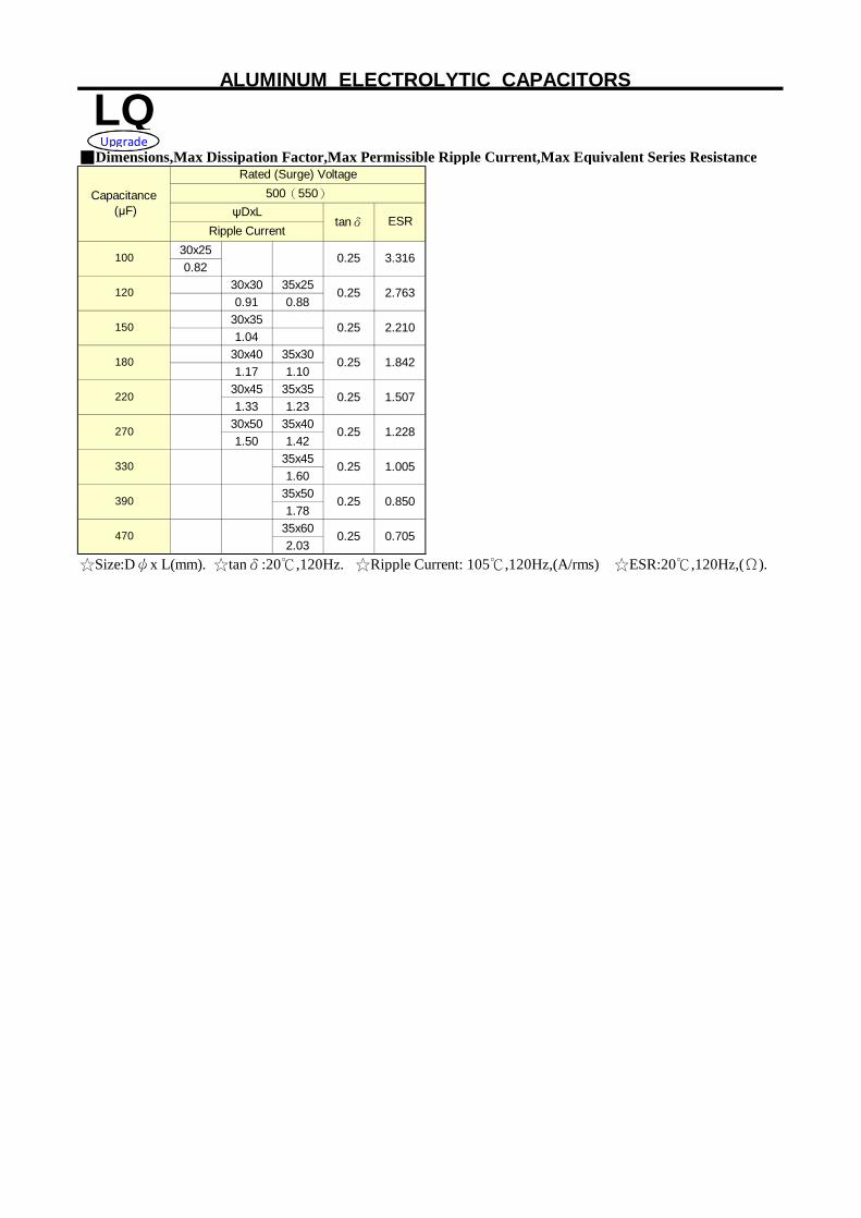
■Dimensions,Max Dissipation Factor,Max Permissible Ripple Current,Max Equivalent Series Resistance
30x250.82
30x30 35x250.91 0.88
30x351.04
30x40 35x301.17 1.10
30x45 35x351.33 1.23
30x50 35x401.50 1.42
35x451.60
35x501.78
35x602.03
☆Size:Dψx L(mm). ☆tanδ:20℃,120Hz. ☆Ripple Current: 105℃,120Hz,(A/rms) ☆ESR:20℃,120Hz,(Ω).
0.25 0.705
0.25
1.507
Rated (Surge) Voltage
470
0.25 1.005
1.228
220 0.25
390 0.850
330
150 0.25 2.210
180 0.25 1.842
270 0.25
3.316
120 0.25 2.763
100 0.25
ALUMINUM ELECTROLYTIC CAPACITORS
LQCapacitance
(μF)500(550)
ψDxLtanδ ESR
Ripple Current
Upgrade

Series
■ Features : 105℃ 7000 hours , Longer life than LQ, LK Snap-in terminal, High ripple current■ Recommended Applications: Smoothing circuit, TV/Monitor,Adapter, SMPS LQ■ Corresponding product to RoHS
■ Specifications
Capacitance Range Capacitance Tolerance
I= Leakage Current (μA) C= Nominal Capacitance (μF) V= Rated Voltage (V)
After applying rated voltage with rated Ripple current for 7000hrs at 105℃,
■ Diagram of Dimensions
■ Multiplier for Ripple Current
Frequency coefficient
120 500 1K
160~250WV 1.00 1.20 1.30
315~450WV 1.00 1.20 1.25
Long Life
-25 ~ +105℃
Leakage Current
± 20 % at 120Hz , 20℃
Shelf Life
Leakage Current (MAX) (20℃)
Dissipation Factor (MAX) (tanδ) (120Hz ,20℃)
Operating Temperature Range
Endurance
Rated Voltage Range 160 ~ 450VDC
Not more than the specified value
39 ~ 2200μF
I≦0.02CV or 3mA whichever is smaller(After rated voltage applied for 5 minutes)
Within±20% of the initial value
Dissipation Factor(tanδ)shall not exceed the values showed in the table of standard rating
Capacitance Change Not more than 200% of the specified value
ALUMINUM ELECTROLYTIC CAPACITORS
Dissipation Factor
High temperature and long life
Characteristics
LK
Item
≧10K
the capacitor shall meet the same requirements as Endurance.After placed at 105℃without voltage applied for 1000 hours,
the capacitor shall meet the following requirement.
0.80
0.80
60(50)
1.50
Freq. (Hz)
1.40Coefficient

■Dimensions,Max Dissipation Factor,Max Permissible Ripple Current,Max Equivalent Series Resistance
22x251.00
22x25 22x251.10 1.10
22x25 22x30 25x251.20 1.20 1.20
22x30 25x25 22x30 25x251.30 1.30 1.30 1.30
22x35 25x30 22x35 25x30 30x251.40 1.40 1.40 1.40 1.40
22x40 25x30 30x25 22x40 25x35 30x251.50 1.50 1.50 1.50 1.50 1.50
22x45 25x35 30x30 22x45 25x35 30x301.70 1.70 1.70 1.70 1.70 1.70
22x50 25x40 30x30 25x40 30x35 35x302.00 2.00 2.00 2.00 2.00 2.00
25x45 30x35 35x30 25x50 30x35 35x302.20 2.20 2.20 2.20 2.20 2.20
25x50 30x40 35x35 30x40 35x352.40 2.42 2.43 2.40 2.40
30x45 35x35 30x50 35x402.70 2.70 2.70 2.70
30x50 35x40 35x452.90 2.90 2.90
35x45 35x503.10 3.10
22x25 25x250.90 0.90
22x25 22x30 25x251.00 1.00 1.00
22x30 25x25 22x35 25x30 30x251.10 1.10 1.10 1.10 1.10
22x30 25x25 22x40 25x30 30x251.20 1.20 1.20 1.20 1.20
22x35 25x30 30x25 22x45 25x35 30x301.30 1.30 1.30 1.30 1.30 1.30
22x40 25x35 30x25 22x50 25x40 30x30 35x301.40 1.40 1.40 1.40 1.40 1.40 1.43
22x45 25x35 30x30 25x45 30x35 35x301.55 1.53 1.53 1.60 1.60 1.60
22x50 25x40 30x30 25x50 30x40 35x351.73 1.75 1.73 1.80 1.83 1.83
25x45 30x35 35x30 30x45 35x352.00 2.00 2.00 2.10 2.05
30x40 35x35 30x50 35x402.20 2.30 2.30 2.30
30x45 35x40 35x452.40 2.45 2.40
35x502.70
☆Size:Dψx L(mm). ☆tanδ:20℃,120Hz. ☆Ripple Current: 105℃,120Hz,(A/rms)
0.15
Ripple Current
0.15
0.15
0.15
0.15
0.15
LK High temperature and long lifeSeries
330
560
ALUMINUM ELECTROLYTIC CAPACITORS
ψDxLtanδ
270 0.15
tanδ
220
0.15
330 0.15
0.15
0.150.15
0.15
0.15
tanδψDxL
0.15
0.15
0.15
0.15
0.15
0.15
250(300)
tanδ
0.15
Rated (Surge) Voltage
0.15
0.15
0.15
0.15
1000
0.15
0.15
390
ψDxL
470
820
1000
1500
820
1200
1800
680
270
0.15
2200
0.15
0.15
Ripple Current
0.15 0.15470
Capacitance (μF)
200(250)
220
180
390
0.15
0.15
0.15
0.150.15
0.150.15
0.15 0.15
0.15 0.15
0.150.15
1500 0.15
1200
Capacitance (μF)
Ripple Current
680
560
Rated (Surge) Voltage160(200) 180(225)
ψDxLRipple Current

Series
■Dimensions,Max Dissipation Factor,Max Permissible Ripple Current,Max Equivalent Series Resistance
22x25 22x250.64 0.64
22x30 22x30 25x250.69 0.69 0.69
22x30 25x25 22x35 25x300.75 0.75 0.75 0.75
22x35 25x30 30x25 22x40 25x30 30x250.82 0.82 0.82 0.85 0.85 0.85
22x40 25x30 30x25 22x45 25x35 30x300.9 0.90 0.90 0.95 0.95 0.95
22x45 25x35 30x30 22x50 25x40 30x301.05 1.05 1.05 1.05 1.05 1.05
25x40 30x35 35x30 25x45 30x35 35x301.20 1.20 1.20 1.20 1.21 1.21
25x50 30x40 35x30 30x40 35x351.35 1.35 1.35 1.35 1.35
30x40 35x35 30x45 35x351.50 1.50 1.45 1.45
30x45 35x40 30x50 35x401.60 1.60 1.55 1.55
35x45 35x501.70 1.70
35x501.90
22x250.40
22x300.46
22x25 22x35 25x250.51 0.52 0.52
22x30 25x25 22x40 25x300.56 0.56 0.58 0.58
22x30 25x25 22x45 25x35 30x250.64 0.64 0.65 0.65 0.65
22x35 25x30 22x50 25x40 30x300.69 0.69 0.73 0.73 0.73
22x40 25x30 30x25 25x45 30x300.75 0.75 0.75 0.82 0.82
22x45 25x35 30x30 25x50 30x40 35x300.82 0.82 0.82 0.96 0.96 0.96
22x50 25x40 30x30 35x25 30x45 35x350.93 0.93 0.95 0.95 1.07 1.07
25x45 30x35 35x30 30x50 35x401.03 1.03 1.02 1.21 1.21
30x40 35x35 35x451.21 1.20 1.40
30x45 35x40 35x501.40 1.38 1.60
35x451.50
35x501.60
☆Size:Dψx L(mm). ☆tanδ:20℃,120Hz. ☆Ripple Current: 105℃,120Hz,(A/rms)
ALUMINUM ELECTROLYTIC CAPACITORS
0.20
56
47
Rated (Surge) Voltage
0.20
0.20
Ripple Current
0.20
0.20
Ripple Current
450(500)
0.20
470
0.20
0.20
0.20
0.20
0.20
0.20
0.20
0.20
0.20
0.20
0.20
0.20
0.20
120
0.20
0.20 0.20
0.20
Capacitance (μF)
0.20
ψDxLtanδ
ψDxL400(450)
680
100
180
150
68
39
82
220
390
270
330
0.20
0.20
0.20
0.20560
470
0.20
390
0.20
330 0.20 0.20
0.20
180
0.20220 0.20
0.200.20
270
0.20120 0.20
0.20150 0.20
100
tanδRipple CurrentRipple Current
0.200.20
0.20
LK High temperature and long life
Rated (Surge) VoltageCapacitance
(μF)315(365) 350(400)
ψDxLtanδ
ψDxL
tanδ
0.20
0.20
82 0.20
Recommended

![140903 PLE Vers2 Präsentation Fikomm [Kompatibilitätsmodus]hamburg.hk24.de/Veranstaltung/Anlagen/VSDB/... · performance or events may differ materially from those in such statements](https://img.dokumen.tips/doc/110x75/5f01da327e708231d40159ba/140903-ple-vers2-prsentation-fikomm-kompatibilittsmodus-performance-or-events.jpg)