
: Efficient solutions for motor control
Product informationMotor contactors DIL MMotor-protectivecircuit-breakers PKZMotor-starters MSC
Contactors DIL
Motor-protectivecircuit-breakers PKZ
Motor-starters MSC
Softstarters DS 4
Drives
Rapid Link
The complete range of contac-tors, efficient motor-startersand controlled drives for themotor circuit. New simple toinstall solutions based on clever communication.
2
1
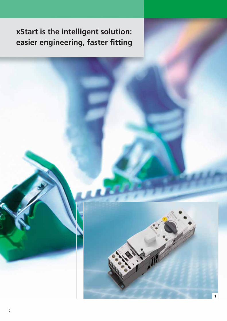
xStart is the intelligent solution:easier engineering, faster fitting
3
2
With Moeller you can meet anychallenge!
Moeller has proved its competence as a partner with high-quality, efficientmotor-related solutions for more than a century. xStart now offers you thecomplete range of products needed forswitching, protecting, starting, runningup and controlling motors. You can relyon our competence in each of theseareas, and we can meet any challengefrom contactors to drive control.
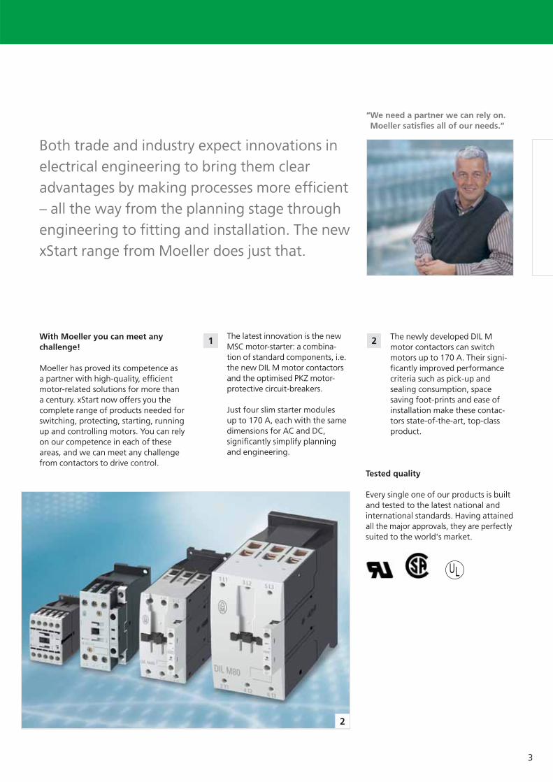
The newly developed DIL Mmotor contactors can switchmotors up to 170 A. Their signi-ficantly improved performancecriteria such as pick-up andsealing consumption, spacesaving foot-prints and ease ofinstallation make these contac-tors state-of-the-art, top-classproduct.
Both trade and industry expect innovations inelectrical engineering to bring them clearadvantages by making processes more efficient– all the way from the planning stage throughengineering to fitting and installation. The newxStart range from Moeller does just that.
The latest innovation is the newMSC motor-starter: a combina-tion of standard components, i.e.the new DIL M motor contactorsand the optimised PKZ motor-protective circuit-breakers.
Just four slim starter modulesup to 170 A, each with the samedimensions for AC and DC, significantly simplify planningand engineering.
“We need a partner we can rely on.Moeller satisfies all of our needs.“
Tested quality
Every single one of our products is builtand tested to the latest national andinternational standards. Having attainedall the major approvals, they are perfectlysuited to the world's market.
1 2
4
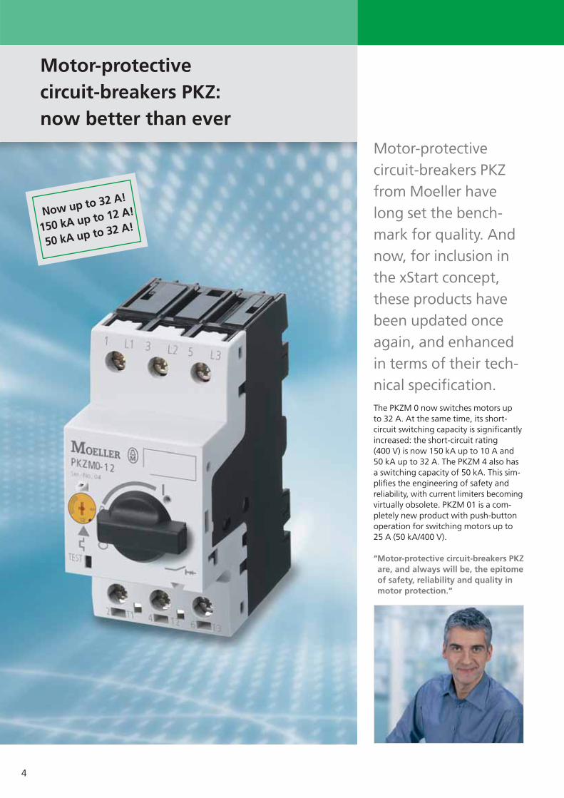
Now up to 32 A!
150 kA up to 12 A!
50 kA up to 32 A!
Motor-protectivecircuit-breakers PKZ:now better than ever
Motor-protective circuit-breakers PKZfrom Moeller havelong set the bench-mark for quality. Andnow, for inclusion inthe xStart concept,these products havebeen updated onceagain, and enhancedin terms of their tech-nical specification.The PKZM 0 now switches motors up to 32 A. At the same time, its short-circuit switching capacity is significantlyincreased: the short-circuit rating (400 V) is now 150 kA up to 10 A and50 kA up to 32 A. The PKZM 4 also hasa switching capacity of 50 kA. This sim-plifies the engineering of safety andreliability, with current limiters becomingvirtually obsolete. PKZM 01 is a com-pletely new product with push-buttonoperation for switching motors up to25 A (50 kA/400 V).
“Motor-protective circuit-breakers PKZare, and always will be, the epitomeof safety, reliability and quality inmotor protection.“

5
45 mm
55 mm
1 2 3 5 6
4
Common accessories throughout thesystem
Whether PKZM 0, PKZM 01 or PKZM 4,the accessories are always the same.Whether On or Off, overload or shortcircuit, differential indication helps tolocate the cause of tripping withoutdelay, every time. The auxiliary contactscan be fitted without tools and are fail-safe in the way they signal every switch-ing state. One particularly convenientcomponent is the NHI-E front auxiliarycontact that can be optionally built intoalready installed and wired circuit-breakers. It goes without saying that allthe auxiliary contacts and releases areworldmarket devices, for all the cus-tomary mains voltages.
Shunt trips and undervoltagetrips
Motor-protective circuit-breakersPKZM 0: from 0 to 32 A
Motor-protective circuit-breakersPKZM 4 from 10 to 65 A
The optionally integrable frontauxiliary contact indicates theswitching position of 1 NO andNC contact or 1 NO contact
Trip-indicating contacts: twocontacts provide differential indi-cation of short circuit or overload
Standard auxiliary contacts withup to three contacts for theOn/Off switching position
The door coupling handle (IP 65) has atripped position in addition to the Onand Off positions.
Motor-protective circuit-breakersPKZM 01 easy to operate by pressingor hitting a button
The new motor-protective circuit-breakers PKZM 01 for motors up to 25 A are ideally suited to small machinesand applications where operation bypressing or even hitting a button is preferred. In addition to the auxiliarycontacts from the PKZM 0 range, specialenclosures with ingress protection IP 65or IP 40 and the appropriate Emergency-Stop buttons are available for these new components. Their short-circuitswitching capacity is 50 kA.
1
2
3
4
5
6

6
DC
DCAC
AC and DC contactors: both the same frame size –simplifies engineering
Great efficiency inplanning and engi-neering with AC andDC contactors isachieved by thembeing the same dimen-sions. With only fourcomponent sizescovering the ratingrange up to 170 Aengineering is furthersimplified.
Definitely useful: up to 32 A, the auxiliarycontact is already built in, and the DCcontactors include a suppressor circuit upto 170 A. From 12 A, the DC contactorshave an electronic drive that removesthe need for coupling relays. With allthese extras already included in the con-tactors, your costs are clearly reduced.
DC contactors now are no biggerthan AC contactors
The new contactors DIL are significantlymore compact than their predecessors,even though, up to 32 A, the auxiliarycontact is included. The advantage ofthis is particularly striking with the DCcontactors that now are the same sizeas their AC counterparts. This makeseverything easier, i.e. planning, engi-neering and fitting, without having toalter the control system, even if the con-trol current has to change for anothercustomer.

7
4 5
3
1
2
“With these new motor contactors,Moeller is definitely on to a winner.They bring real advantages from theplanning all the way to the fittingcosts.”
This reduces the cost of yourcontrol panel
The space-saving is achieved not just bythe reduced component dimensions,but also due to the lower heat dissipa-tion that, particularly with the DC con-tactors, helps keep the cabinet sizedown and saves the cost of a fan. Thesignificantly reduced sealing consump-tion achieved by innovative, electronicdrives makes this possible. The MoellerDC contactors from 17 up to 72 A have
a sealing consumption of only 0.5 Watt,even those at 170 A only use 1.5 Watt.This also results in lower power con-sumption for the whole installation.
No compromise where termi-nation reliability is concerned
DIL contactors up to 170 A have boxterminals with two clamping chambers,allowing unequal cable cross-sectionsto be terminated absolutely securely,even in strongly vibrating machines.This makes wiring easier and cuts downon associated errors.
The benefits of the electroni- cally controlled drive
All DC motor contactors from DIL M17 have an electronically controlled drivethat offers the following advantages:
• Significantly less heat dissipation dueto reduced sealing consumption
• Smaller control transformers becauseof lower pick-up consumption
• Direct actuation from the PLC withoutcoupling contactors up to 32 A.
The new auxiliary contacts DIL Aperfectly complement the newmotor contactors DIL M.
Overload relays Z protect themotor against phase failure oroverload. Their auxiliary contactsswitch the motor contactor off,and signal the fault. These relaysare suitable for protecting EEx e-motors according to ATEX 100a guideline.
1
2
3
4
5
8
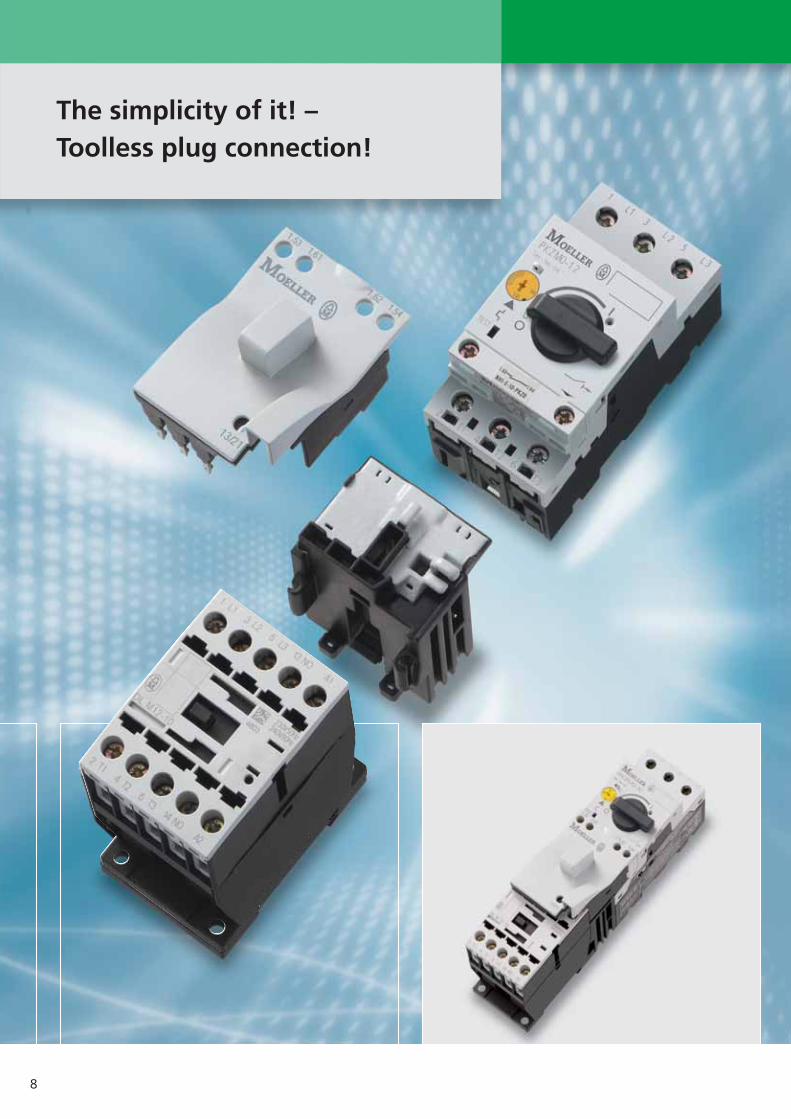
The simplicity of it! – Toolless plug connection!

9
Using the new xStartmotor-starter combina-tions it is possible tocreate the best solu-tions from standardproducts even moreeasily and efficiently.
Moeller has optimised the DIL and PKZstandard products in such a way that,by using simple toolless plug connectors,they can be assembled to form reliablemotor-starters. Without the need fortools! The motor-starter combinationsMSC can also be supplied as completedevices. Costs for fitting and wiring canbe considerably reduced in this way.Costs for testing are cut and errors areprevented from the start. Another ad-vantage lies in increased safety duringmaintenance work where removal ofthe combination plug connector pro-duces a visible isolating gap. This Moellertechnology is available on our direct-on-line and reversing starters up to 15.5 A.
“The toolless plug connection is very quick to fit – just what I need to reduce costs.”
Slim solutions: DOL starters fromstandard components
The new direct-on-line starters builtfrom standard components are availablein four slim frame sizes. The contactorand the protective switch are of thesame compact width dimension. Thusyou lose not a millimetre of control panelspace. The convenient MSC motor-starters using toolless plug connectiontechnology are available up to 15.5 A andrequire only a top-hat rail for mounting.The mechanical connector ensures asecure hold and the electrical connectorprovides optimum reliability and safety.Complete mounting connectors areoffered for DOL and reversing startersfrom 17 up to 32 A. This prevents fittingerrors and cuts down on wiring time.
Plug and go: reversing starters fromstandard components
The reversing starters offer distinct ad-vantages to the assembler. Instead oflaboriously having to tighten up 21screws, a small number of componentssimply plug together. This of coursespeeds up fitting work, and means fewererrors and a very clearly laid outswitching installation.
Speedier wiring using spring-loadedterminations
Moeller provides proven quality withtension clamp terminals. Numeroustests have proved that contactors andmotor-protective circuit-breakers arejust as securely wired in this way as byscrew connection – even in stronglyvibrating machines. But wiring workusing tension clamp terminals is verymuch quicker to do. The main currentpaths on PKZM 0 and motor contactorsup to 12 A all use spring-loaded termi-nals. The sundries for termination arealways available for both screw andtension clamp connection.

10
up to 12 A
up to 32 A
up to 65 A
up to 150 A
Reversing starters and star-deltacombinations up tp 15.5 A can becombined without tools.
Moeller has significantly reduced thewiring costs with reversing and star-delta combinations using tool-less plugconnections. Moeller DIL M contactorsup to 15.5 A feature sockets in whichthe connection elements are simplyplugged in as standard and withoutadditional expense. Thus, costs associated with operations such as cutting wires to length, stripping ofinsulation, work on the wire ends andprovision of conductors with markings,as well as application of defined torqueswhen tightening screws, have beentotally eliminated. Inspection of 21electrical connections between themains and the star and delta contactorare reduced to a simple visual inspection.A measurement with test device probescan be undertaken without having toremove the connection elements.
Reversing starters with mechanical interlock – as compact as it gets!
Precious space is provided in the control panel by the narrow widths ofjust 55 mm on contactors up to 65 A.The mechanical interlocks which areusually found on reversing contactorcombinations do not require anyadditional space from Moeller. Thesmart, patented solution is a plasticsphere. It is simply inserted into the side cavities provided on both contactors and reliably prevents simultaneous switch on. Furthermore,a lateral clearance between the contactors is not required – the contactors can be mounted andwired side-by-side. Generally, DC contactors in the rangeup to 65 A have a longer depth thanAC contactors. However, with xStart –thanks to electronically supportedmagnet systems – all dimensions of the DC variants are identical to those
of the AC variants. If the manufacturerof mass produced machines uses differing control voltages, the testingof the control panel layout is now eliminated, the DC contactors are simply positioned on the top-hat rail or mounting plate in the same manneras the AC variants. The heat dissipation limits the packingdensity in control panels. Solutionswhich are possible from a purelymechanical viewpoint cannot be implemented due to heat dissipationconsiderations. The extremely low holding power of just 0.5 W withMoeller DC contactors now enablessolutions which were previously impossible.

11
www.moeller.net/select
Simply select tested motor starters to approval types I and II
www.moeller.net/select
The DOL starter (complete unit) consistsof a Motor-protective circuit-breakerPKMZ 0 and a contactor DILM.
Moeller provides a PC-based electronic selection program for motor starters inaddition to the comprehensive selectionpage in the Moeller main catalogue.This program considers various
operating voltages, short-circuit ratingsand coordination types, as well as fuseless and fused combinations. This small program is available fromMoeller free of charge on the Internet.Moeller has provided the practically-minded with a carton selection slider for a number of years.
Optimum compatibility:Starters and busbar adapters
The xStart system has been extended by the new busbar adapter, which iscompatible with the busbar system andthe system accessories from Wöhner,the market leader in this field. Conformity to the standard ensures that busbar adapters for 60 mm busbarclearances fit all similar manufacturers
systems. An additional benefit is thatthe busbar adapter material usedworldwide is a standard copper profile. Prefabricated connectors or the newtool-less plug connections are availablefor establishing connections betweencircuit-breakers and contactors. With large and uniform requirements,Moeller supplies the adapter fitted complete with switchgear for DOL andreversing starters.
Mounting rail adapter with new flexibility
The switchgear interconnected withthe three phase commoning links isgenerally snapped onto a mounting rail.The result is an additional benefit wherecomponents can be easily removed froman interconnected group by offsettingthe adapter mounting rail withouthaving to disassemble the entire threephase commoning link.

12
33
25
4
4
1 11
1
5
52
5
DILM40 – DILM170
DILM7 – DILM12DILM17 – DILM32
DILM basic units
AC-3 AC-3 Open
380 V 380 V Ith =400 V 400 V Ie
Ie P A
A kW
3-pole 7 3 20
7 3
9 4
9 4
12 5.5
12 5.5
15.5 7.5
15.5 7.5
4-pole – –
3-pole 18 7.5 35
18 7.5 35
25 11 40
25 11 40
32 15 40
32 15 40
40 18.5 50
50 22 65
65 30 80
72 37 80
80 37 110
95 45
115 55 160
150 75
170 90 185
Contactors DIL M7 – 170Contactor relays DILA
1. Basic units
2. Suppressor 1)
3. Auxiliary contact modules, 2-pole
4. Auxiliary contact modules, 4-pole
5. Overload relays
1) For AC operated contactors 50-60 Hz;in DC operated contactors, the suppressor circuit is incorporated.Note drop-out delay

13
Contacts Can be combined AC operation DC actuationwith auxiliarycontact
Part no. Part no. Part no. Part no. Part no. Part no.Article no. Article no. Article no. Article no.. Article no. Article no.230 V 50 Hz 230V 50/60 Hz 24 V 50/60 Hz 110 V 50 Hz, 110V 50/60Hz 24 V DC240 V 60 Hz 120 V 60 Hz
1 N/O DILM32-XHI.. DILM7-10(...) DILM7-10(...) DILM7-10(...) DILM7-10(...) DILM7-10(...) DILM7-10(24VDC)DILA-XHI(V).. 276550 276558 276554 276547 276556 276565
1 N/C DILA-XHI(V).. DILM7-01(...) DILM7-01(...) DILM7-01(...) DILM7-01(...) DILM7-01(...) DILM7-01(24VDC)276585 276593 276589 276582 276591 276600
1 N/O DILM32-XHI.. DILM9-10(...) DILM9-10(...) DILM9-10(...) DILM9-10(...) DILM9-10(...) DILM9-10(24VDC)DILA-XHI(V).. 276690 276698 276694 276687 276696 276705
1 N/C DILA-XHI(V).. DILM9-01(...) DILM9-01(...) DILM9-01(...) DILM9-01(...) DILM9-01(...) DILM9-01(24VDC)276725 276733 276729 276722 276731 276740
1 N/O DILM32-XHI.. DILM12-10(...) DILM12-10(...) DILM12-10(...) DILM12-10(...) DILM12-10(...) DILM12-10(24VDC)DILA-XHI(V).. 276830 276838 276834 276827 276836 276845
1 N/C DILA-XHI(V).. DILM12-01(...) DILM12-01(...) DILM12-01(...) DILM12-01(...) DILM12-01(...) DILM12-01(24VDC)276865 276873 276869 276862 276871 276880
1 N/O DILM32-XHI.. DILM15-10(...) DILM15-10(...) DILM15-10(...) DILM15-10(...) – DILM15-10(24VDC)DILA-XHI(V).. 290058 290066 290062 290055 290073
1 N/C DILA-XHI(V).. DILM15-01(...) DILM15-01(...) DILM15-01(...) DILM15-01(...) – DILM15-01(24VDC)290093 290101 290097 290090 290108
– DILM32-XHI.. DILMP20(...) DILMP20(...) DILMP20(...) DILMP20(...) – DILMP20(24VDC)DILA-XHI(V).. 276970 276978 276974 276967 276985
1 N/O DILM32-XHI.. DILM17-10(...) DILM17-10(...) DILM17-10(...) DILM17-10(...) DILM17-10(...) DILM17-10(RDC24)DILA-XHI(V).. 277004 277012 277008 277001 277010 277018
1 N/C DILA-XHI(V).. DILM17-01(...) DILM17-01(...) DILM17-01(...) DILM17-01(...) DILM17-01(...) DILM17-01(RDC24)277036 277044 277040 277033 277042 277050
1 N/O DILM32-XHI.. DILM25-10(...) DILM25-10(...) DILM25-10(...) DILM25-10(...) DILM25-10(...) DILM25-10(RDC24)DILA-XHI(V).. 277132 277140 277136 277129 277138 277146
1 N/C DILA-XHI(V).. DILM25-01(...) DILM25-01(...) DILM25-01(...) DILM25-01(...) DILM25-01(...) DILM25-01(RDC24)277164 277172 277168 277161 277170 277178
1 N/O DILM32-XHI.. DILM32-10(...) DILM32-10(...) DILM32-10(...) DILM32-10(...) DILM32-10(...) DILM32-10(RDC24)DILA-XHI(V).. 277260 277268 277264 277257 277266 277274
1 N/C DILA-XHI(V).. DILM32-01(...) DILM32-01(...) DILM32-01(...) DILM32-01(...) DILM32-01(...) DILM32-01(RDC24)277292 277300 277296 277289 277298 277306
– DILM150-XHI(V).. DILM40(...) DILM40(...) DILM40(...) DILM40(...) DILM40(...) DILM40(RDC24)DILM1000-XHI(V).. 277766 277774 277770 277763 277772 277780
– DILM50(...) DILM50(...) DILM50(...) DILM50(...) DILM50(...) DILM50(RDC24)277830 277838 277834 277827 277836 277844
– DILM65(...) DILM65(...) DILM65(...) DILM65(...) DILM65(...) DILM65(RDC24)277894 277902 277898 277891 277900 277908
– DILM72(...) – – – – DILM72(RDC24)107670 107671
– DILM80(...) DILM80(...) DILM80(...) DILM80(...) DILM80(...) DILM80(RDC24)239402 239414 239406 239399 239408 239416
– DILM95(...) DILM95(...) DILM95(...) DILM95(...) DILM95(...) DILM95(RDC24)239480 239488 239484 239477 239486 239510
– DILM115(RAC240) DILM115(RAC240) DILM115(RAC24) DILM115(RAC120) DILM115(RAC120) DILM115(RDC24)239548 239548 239545 239547 239547 239555
– DILM150(RAC240) DILM150(RAC240) DILM150(RAC24) DILM150(RAC120) DILM150(RAC120) DILM150(RDC24)239588 239588 239585 239587 239587 239591
– DILM170(RAC240) DILM170(RAC240) DILM170(RAC24) DILM170(RAC120) DILM170(RAC120) DILM170(RDC24)107013 107013 107010 107012 107012 107016
The listed auxiliary and main contacts up to 12 A are available with springloaded terminals.The auxiliary contact modules listed for the DILA contactor relay can also be used for the DILM contactors up to 32 A.Auxiliary contact members: DILA-XHI to EN 50005, DILM32-XHI to DIN 50012The 2- and 4-pole DILM32-XHI... auxiliary contact modules can not be combined with DILM...-01 contactors.

14
DILM7...DILM9...DILM12...DILM15...DILM17...DILM25...DILM32...
DILM40...DILM50...DILM65...DILM80...DILM95...DILM115...DILM150...
DILM7-10...DILM9-10...DILM12-10...DILM15-10...DILM17-10...DILM25-10...DILM32-10...
Ith = Ie Contacts Can be combined Part no. Article no.with basic units
open
N/CE = Early-make contactsA N/OL = Late-break contacts
2-pole 10 1 N/O 1 N/C DILM32-XHI11 277376
– 2 N/C DILM32-XHI02 277375
4-pole 2 N/O 2 N/C DILM32-XHI22 277377
2-pole 2 N/O – DILA-XHI20 276422
1 N/O 1 N/C DILA-XHI11 276421
– 2 N/C DILA-XHI02 276420
1 N/OE 1 N/CL DILA-XHIV11 276423
4-pole 4 N/O – DILA-XHI40 276428
3 N/O 1 N/C DILA-XHI31 276427
2 N/O 2 N/c DILA-XHI22 276426
1 N/O 3 N/C DILA-XHI13 276425
– 4 N/C DILA-XHI04 276424
1 N/O, 1 N/OE 1 N/C, 1 N/CL DILA-XHIV22 276429
2-pole 10 2 N/O – DILM150-XHI20 277945
1 N/O 1 N/C DILM150-XHI11 277946
– 2 N/C DILM150-XHI02 277947
4-pole 4 N/O – DILM150-XHI40 277948
3 N/O 1 N/C DILM150-XHI31 277949
2 N/O 2 N/C DILM150-XHI22 277950
1 N/O 3 N/C DILM150-XHI13 277951
– 4 N/C DILM150-XHI04 277952
1 N/O, 1 N/OE 1 N/C, 1 N/CL DILM150-XHIV22 277953
– 2-pole 1 N/O 1 N/C DILM1000-XHI11-SI 278425
1 N/O 1 N/C DILM150-XHIA111) 283463
The listed auxiliary and main contacts up to 12 A are available with springloaded terminals.The auxiliary contact modules listed for the DILA contactor relay can also be used for the DILM contactors up to 32 A.Auxiliary contact members: DILA-XHI to EN 50005, DILM32-XHI to DIN 50012The 2- and 4-pole DILM32-XHI... auxiliary contact modules can not be combined with DILM...-01 contactors.
1) NEW: Also available as 4-pole version DILM150-XHIA22 with terminal markings 53/54, 61/62, 71/72 and 83/84 (Article no. 283464) in order to avoid duplication of terminal markings on combinations with auxiliary contact on the side.
2) The following applies for all auxiliary contact modules: Ie=3 A for AC-15 at 380 V, 400 V, 415 V
Auxiliary contact modules2)

15
A2
A1
A1
A2
A1
A2
Accessories
Us For use with Part no. Article no. NotesV AC
Suppressor
Varistor suppressor
Varistor suppressors withbuilt-in LED
RC suppressor
ConnectorFor the mechanicalconnection of contactorsto groups of components
Mechanical interlock
For AC operated contactors,50-60 Hz,DC operated contactors have an integrated suppressorNote drop-out delay
For AC operated contactors,50-60 Hz,DC operated contactors have an integrated suppressorNote drop-out delay
For AC operated contactors,50-60 Hz,DC operated contactors have an integrated suppressorNote drop-out delay
0 mm distance between contactors
For two contactors with AC or DCoperation, distance betweencontactors 0 mm, mechanical lifespan 2.5 X 10 6 switching operations, additional auxiliary contact modules can be fitted
281208
281209
281210
281211
281212
281213
281214
281215
281216
281217
281218
281219
281220
281221
281222
281223
281224
281225
281199
281200
281201
281202
281203
281204
281205
281206
281207
281227
281226
281196
281197
281198
240081
DILM12-XSPV48
DILM12-XSPV130
DILM12-XSPV240
DILM12-XSPV500
DILM32-XSPV48
DILM32-XSPV130
DILM32-XSPV240
DILM32-XSPV500
DILM95-XSPV48
DILM95-XSPV130
DILM95-XSPV240
DILM95-XSPV500
DILM12-XSPVL48
DILM12-XSPVL240
DILM32-XSPVL48
DILM32-XSPVL240
DILM95-XSPVL48
DILM95-XSPVL240
DILM12-XSPR48
DILM12-XSPR240
DILM12-XSPR500
DILM32-XSPR48
DILM32-XSPR240
DILM32-XSPR500
DILM95-XSPR48
DILM95-XSPR240
DILM95-XSPR500
DILM32-XVB
DILM150-XVB
DILM12-XMV
DILM32-XMV
DILM65-XMV
DILM150-XMV
DILM7 – DILM15DILMP20DILA
DILM17 – DILM32
DILM40 – DILM95
DILM7 – DILM15DILMP20DILADILM17 – DILM32
DILM40 – DILM95
DILM7 – DILM15DILMP20DILA
DILM17 – DILM32
DILM40 – DILM95
DILM7 – DILM65DILA
DILM80 – DILM150DILM7 – DILM15DILMP20DILA
DILM17 – DILM32
DILM40 – DILM65
DILM80 – DILM150
24 – 48
48 – 130
130 – 240
240 – 500
24 – 48
48 – 130
130 – 240
240 – 500
24 – 48
48 – 130
130 – 240
240 – 500
24 – 48
130 – 240
24 – 48
130 – 240
24 – 48
130 – 240
24 – 48
130 – 240
240 – 500
24 – 48
110 – 240
240 – 500
24 – 48
110 – 240
240 – 500
16
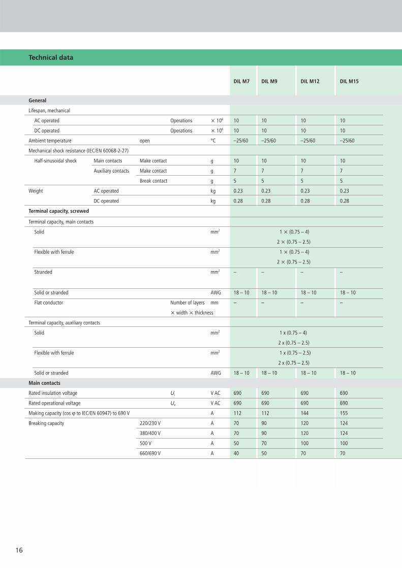
Technical data
DIL M7 DIL M9 DIL M12 DIL M15
General
Lifespan, mechanical
AC operated Operations x 106 10 10 10 10
DC operated Operations x 106 10 10 10 10
Ambient temperature open °C –25/60 –25/60 –25/60 –25/60
Mechanical shock resistance (IEC/EN 60068-2-27)
Half-sinusoidal shock Main contacts Make contact g 10 10 10 10
Auxiliary contacts Make contact g 7 7 7 7
Break contact g 5 5 5 5
Weight AC operated kg 0.23 0.23 0.23 0.23
DC operated kg 0.28 0.28 0.28 0.28
Terminal capacity, screwed
Terminal capacity, main contacts
Solid mm2 1 x (0.75 – 4)
2 x (0.75 – 2.5)
Flexible with ferrule mm2 1 x (0.75 – 4)
2 x (0.75 – 2.5)
Stranded mm2 – – – –
Solid or stranded AWG 18 – 10 18 – 10 18 – 10 18 – 10
Flat conductor Number of layers mm – – – –
x width x thickness
Terminal capacity, auxiliary contacts
Solid mm2 1 x (0.75 – 4)
2 x (0.75 – 2.5)
Flexible with ferrule mm2 1 x (0.75 – 2.5)
2 x (0.75 – 2.5)
Solid or stranded AWG 18 – 10 18 – 10 18 – 10 18 – 10
Main contacts
Rated insulation voltage Ui V AC 690 690 690 690
Rated operational voltage Ue V AC 690 690 690 690
Making capacity (cos v to IEC/EN 60947) to 690 V A 112 112 144 155
Breaking capacity 220/230 V A 70 90 120 124
380/400 V A 70 90 120 124
500 V A 50 70 100 100
660/690 V A 40 50 70 70

17
Technical data
DIL M17 DIL M25 DIL M32 DIL M40 DIL M50 DIL M65 DIL M80 DIL M95 DIL M115 DIL M150 DIL M170
10 10 10 10 10 10 10 10 10 10 10
10 10 10 10 10 10 10 10 10 10 10
–25/60 –25/60 –25/60 –25/60 –25/60 –25/60 –25/60 –25/60 –25/60 –25/60 –25/60
10 10 10 10 10 10 10 10 10 10 10
7 7 7 7 7 7 7 7 7 7 7 7
5 5 5 5 5 5 5 5 5 5 5 5
0.42 0.42 0.42 0.9 0.9 0.9 2 2 2 2 2
0.48 0.48 0.48 1.1 1.1 1.1 2.1 2.1 2.1 2.1 2.1
1 x (0.75 – 16) 1 x (2.5 – 16) –
2 x (0.75 – 10) 2 x (2.5 – 16)
1 x (0.75 – 16) 1 x (2.5 – 35) 1 x (4 – 70) 1 x (10 – 95)
2 x (0.75 – 10) 2 x (2.5 – 25) 2 x (4 – 50) 2 x (10 – 70)
1 x 16 1 x (16 – 50) 1 x (16 – 95) 1 x (16 – 120)
2 x (16 – 35) 2 x (16 – 70) 2 x (16 – 95)
18 – 6 18 – 6 18 – 6 12 – 2 12 – 2 12 – 2 8 – 3/0 8 – 3/0 8 – 3/0 8 – 3/0 8 – 3/0
– – – 2 x (6 x 9 x 0.8) 2 x (6 x 16 x 0.8)
1 x (0.75 – 4) 1 x (0.75 – 4)
2 x (0.75 – 4) 2 x (0.75 – 2.4)
1 x (0.75 – 2.5) 1 x (0.75 – 2.5)
2 x (0.75 – 2.5) 2 x (0.75 – 2.5)
18 – 14 18 – 14 18 – 14 18 – 14 18 – 14 18 – 14 18 – 14 18 – 14 18 – 14 18 – 14 18 – 14
690 690 690 690 690 690 1000 1000 1000 1000 1000
690 690 690 690 690 690 1000 1000 1000 1000 1000
238 350 384 560 700 910 1120 1330 1610 2100 2100
170 250 320 400 500 650 800 950 1150 1500 1500
170 250 320 400 500 650 800 950 1150 1500 1500
170 250 320 400 500 650 800 950 1150 1500 1500
120 150 180 250 320 370 650 800 1100 1200 1320
DIL M72

18
18 45 68
45
36
8.7 8.7 8.7 8.7 (5.1)
6.5
75
116.3
3.2
11.6 11.6
4.5
17.7
10.6(6.4)
38 7160.4
85
45
4.8
138.7
6.5
97.4
4.5
Technical data
DIL M7 DIL M9 DIL M12 DIL M15
AC
AC-1 actuation
Conventional free air thermal Open at 40 °C A 22 22 22 22
Current 3-pole 50 – 60 Hz at 60 °C A 20 20 20 20
AC actuation
Rated operational current, AC-3 220/230 V Ie A 7 9 12 15.5
open, 50 – 60 Hz, 3-pole 380/400 V Ie A 7 9 12 15.5
500 V Ie A 5 7 10 12.5
660/690 V Ie A 4 5 7 9
Motor rating 220/230 V P kW 2.2 2.5 3.5 4
380/400 V P kW 3 4 5.5 7.5
500 V P kW 3.5 4.5 7 7.5
660/690 V P kW 3.5 4.5 6.5 7
Magnet systems
Pick-up and drop-out values
AC operated Pick-up x Uc 0.8 – 1.1 0.8 – 1.1 0.8 – 1.1 0.8 – 1.1
DC operated Pick-up x Uc 0.8 – 1.1 0.8 – 1.1 0.8 – 1.1 0.8 – 1.1
Coil consumption from cold and 1.0 x Uc
AC operated 50 Hz coil Pick-up VA 24 24 24 2460 Hz coil 30 30 30 30
Sealing VA 3.4 3.4 3.4 3.44.4 4.4 4.4 4.4
W 1.2 1.2 1.2 1.21.4 1.4 1.4 1.4
DC operated Pick-up W 3 3 4.5 4.5
Sealing W 3 3 4.5 4.5
Dimensions
DIL M7 – DIL M15, DILA with auxiliary contact module DIL M17 – DIL M32 basic unit with auxiliary contact module

19
6.9
4.734.4
113.8
132.1
146.75
55
57 86.4
104
90
111
82.5
85.5
142
160
76.5
57 170
156
Technical data
Dimensions
DIL M17 DIL M25 DIL M32 DIL M40 DIL M50 DIL M65 DIL M80 DIL M95 DIL M115 DIL M150 DIL M170
40 45 45 60 80 98 110 130 160 190 225
35 40 40 50 65 80 90 110 130 160 185
18 25 32 40 50 65 72 80 95 115 150 170
18 25 32 40 50 65 72 80 95 115 150 170
18 25 32 40 50 65 72 80 95 115 150 170
12 25 18 25 32 37 37 65 80 93 100 150
5 7.5 10 12.5 15.5 20 22 25 30 37 48 52
7.5 11 15 18.5 22 30 37 37 45 55 75 90
12 17.5 23 28 36 47 45 58 70 85 110 120
11 14 17 23 30 35 35 63 75 90 96 140
0.8 – 1.1 0.8 – 1.1 0.8 – 1.1 0.8 – 1.1 0.8 – 1.1 0.8 – 1.1 0.8 – 1.1 0.8 – 1.1 0.8 – 1.1 0.8 – 1.1 0.8 – 1.1
0.7 – 1.2 0.7 – 1.2 0.7 – 1.2 0.7 – 1.2 0.7 – 1.2 0.7 – 1.2 0.7 – 1.2 0.7 – 1.2 0.7 – 1.2 0.7 – 1.2 0.7 – 1.2
52 52 52 149 149 149 310 310 180 180 18067 67 67 178 178 178 345 345 170 170 170
7.1 7.1 7.1 16.0 16.0 16.0 26.0 26.0 3.1 3.1 3.18.7 8.7 8.7 19.0 19.0 19.0 30.0 30.0 3.1 3.1 3.1
2.1 2.1 2.1 4.3 4.3 4.3 5.8 5.8 2.1 2.1 2.12.6 2.6 2.6 5.3 5.3 5.3 7.1 7.1 2.1 2.1 2.1
12 at 24 V 12 at 24 V 12 at 24 V 24 at 24 V 24 at 24 V 24 at 24 V 90 at 24 V 90 at 24 V 149 at 24 V 149 at 24 V 149 at 24 V
0.5 at 24 V 0.5 at 24 V 0.5 at 24 V 0.5 at 24 V 0.5 at 24 V 0.5 at 24 V 1.3 at 24 V 1.3 at 24 V 2.1 at 24 V 2.1 at 24 V 2.1 at 24 V
DIL M40 – DIL M72 basic unit with auxiliary contact module DIL M80 – DIL M170 basic unit with auxiliary contact module
DIL M72

20
AC-15
380 V400 V415 V
Ie Ith
A A
DILA...
DILM7...DILM9...DILM12...DILM15...DILM17...DILM25...DILM32...
DILA-40...DILA-31...
DILM7...DILM9...DILM12...DILM15...DILM17...DILM25...DILM32...
DILA contactor relays
DILA auxiliary contact modules
Contacts AC-15
380 V400 V415 V
Ie
A
Ith
A
Can be combinedwith auxiliarycontact
AC operation DC operation
Part no. Part no. Part no.
Article no. Article no. Article no.
230 V 50 Hz 24 V 50/60 Hz 110 V 50 Hz 24 V DC240 V 60 Hz 120 V 60 Hz
4 N/O – 4 10 DILA-XHI(V)... DILA-40(...) DILA-40(...) DILA-40(...) DILA-40(...)276329 276333 276326 276344
3 N/O 1 N/C 4 10 DILA-XHI(V)... DILA-31(...) DILA-31(...) DILA-31(...) DILA-31(...)276364 276368 276361 276379
2 N/O 2 N/C 4 10 DILA-XHI(V)... DILA-22(...) DILA-22(...) DILA-22(...) DILA-22(...)276399 276403 276396 276414
The listed auxiliary and main contacts up to 12 A are available with springloaded terminals.The auxiliary contact modules listed for the DILA contactor relay can also be used for the DILM contactors up to 32 A.Auxiliary contact members: DILA-XHI to EN 50005, DILM32-XHI to DIN 50012The DILA-22 contactor relay can not be combined with the 4-pole auxiliary contact module.
Contacts Rated operating Conventional current, Can be combined Part no.current open at 60 °C with basic unit Article no.
2-pole – 2 N/C 3 16 DILA-XHI02276420
1 N/O 1 N/C DILA-XHI11276421
2 N/O – DILA-XHI20276422
1 N/OE 1 N/CL DILA-XHIV11276423
4-pole – 4 N/C DILA-XHI04276424
1 N/O 3 N/C DILA-XHI13276425
2 N/O 2 N/C DILA-XHI22276426
3 N/O 1 N/C DILA-XHI31276427
4 N/O – DILA-XHI40276428
1 N/O, 1 N/OE 1 N/C, 1 N/CL DILA-XHIV22276429
a Dimensions Page 18
Basic units withinterlocked opposing contacts
N/CE = Early-make contactsN/OL = Late-break contacts

21
Technical data
DIL A DIL A-XHI...
General
Lifespan, mechanical
AC operated Operations x 106 20 10
DC operated Operations x 106 20 10
Ambient temperature
open °C –25/60 –25/60
Weight
AC operated kg 0.23 0.05
DC operated kg 0.28 0.05
Terminal capacity
Screw terminals
Solid mm2 1 x (0.75 – 4)
2 x (0.75 – 2.5)
Flexible with ferrule mm2 1 x (0.75 – 2.5)
2 x (0.75 – 2.5)
Solid or stranded AWG 18 – 14
Contacts
Rated insulation voltage Ui V AC 690 690
Rated operational voltage Ue V AC 690 500
Rated operational current
AC-15 220/240 V Ie A 6 6
380/415 V Ie A 4 3
500 V Ie A 1.5 –
DC-13 1) DC-13 L/R F 15 ms
Contacts in series:
1 24 V A 10 10
Fault frequency at Ue = 24 V DC, Umin = 17 V, Imin = 5.4 mA Fault rate HF < 10-8, < 1 failure to 100 million switching operations
Magnet systems
Pick-up and drop-out values
AC operated
50 Hz single-voltage coil and 50/60 Hz dual-voltage coil Pick-up x Uc 0.8 – 1.1 –
Dual-frequency coil 50/60 Hz Pick-up x Uc 0.8 – 1.1 –
DC operated 2)
Pick-up voltage Pick-up x Uc 0.8 – 1.1 –
Without auxiliary contact module (40 °C) Pick-up x Uc 0.7 – 1.3 –
Power consumption
50 Hz single-voltage coil and 50/60 Hz dual-voltage coil Pick-up VA 24 –
50 Hz single-voltage coil and 50/60 Hz dual-voltage coil Sealing VA 4 –
Sealing W 1.2 –
DC operated Pick-up = Sealing W 3 –
Notes 1) Making and breaking currents to DC-13 time constant as stated2) Smoothed DC or three-phase bridge rectifier

22
2 4 6 98 96 A2 14/22
97 95
2 4 6 98 96 14/22
97 95
2 4 6 98 96
97 95
2 4 6 98 96
97 95
DILM7,DILM9,DILM12,DILM15,
DIULM7,DIULM9,DIULM12,
SDAINLM12,SDAINLM16,SDAINLM22
For use with
Article no.Part no.Short-circuitprotectionCoordination typegG/gL A“1“ “2“
DILM17,DILM25,DILM32,
DIULM17,DIULM25,DIULM32
SDAINLM30,SDAINLM45,SDAINLM55
DILM40,DILM50,DILM65,
DIULM40,DIULM50,DIULM65
SDAINLM70,SDAINLM90,SDAINLM115
DILM80,DILM95,DILM115,DILM150,DILM170,
DIULM80,DIULM95,DIULM115,DIULM150,
SDAINLM140,SDAINLM165,SDAINLM200,SDAINLM260
0.1 – 0.16 25 0.5 ZB12-0,16 278431
0.16 – 0.24 1 ZB12-0,24 278432
0.24 – 0.4 2 ZB12-0,4 278433
0.4 – 0.6 4 ZB12-0,6 278434
0.6 – 1 4 ZB12-1,0 278435
1 – 1.6 6 ZB12-1,6 278436
1.6 – 2.4 10 ZB12-2,4 278437
2.4 – 4 16 ZB12-4 278438
4 – 6 20 ZB12-6 278439
6 – 10 50 25 ZB12-10 278440
9 – 12 ZB12-12 278441
12 – 16 ZB12-16 290168
0.1 – 0.16 25 0.5 ZB32-0,16 278442
0.16 – 0.24 1 ZB32-0,24 278443
0.24 – 0.4 2 ZB32-0,4 278444
0.4 – 0.6 4 ZB32-0,6 278445
0.6 – 1 4 ZB32-1,0 278446
1 – 1.6 6 ZB32-1,6 278447
1.6 – 2.4 10 ZB32-2,4 278448
2.4 – 4 16 ZB32-4 278449
4 – 6 20 ZB32-6 278450
6 – 10 50 25 ZB32-10 278451
10 – 16 63 35 ZB32-16 278452
16 – 24 100 35 ZB32-24 278453
24 – 32 125 63 ZB32-32 278454
6 – 10 50 25 ZB65-10 278455
10 – 16 63 35 ZB65-16 278456
16 – 24 63 50 ZB65-24 278457
24 – 40 125 63 ZB65-40 278458
40 – 57 160 80 ZB65-57 278459
50 – 65 160 100 ZB65-65 278460
25-35 125 100 ZB150-35 278461
35-50 160 125 ZB150-50 278462
50-70 250 160 ZB150-70 278463
70-100 315 200 ZB150-100 278464
95-125 315 250 ZB150-125 278465
120-142 315 250 ZB150-150 278466
315 250 ZB150-175 107316
ZB overload relays
ZB12 overload relaysSingle-phasing sensitivity toIEC/EN 60947,VDE 0660 Part 102Direct fitting
Overload releasesetting range
Ir
A
Overload release:tripping class 10 A
Short-circuit protection:when fitting directly, note maximum admissible fuse for thecontactor.
Suitable for the protection of EExe-motors. EU prototype testcertificate available on request.
Overload release:tripping class 10 A
Short-circuit protection:when fitting directly, note maximum admissible fuse for thecontactor.
Suitable for the protection of EExe-motors. EU prototype test certificate available on request.
ZB32 overload relaysSingle-phasing sensitivity toIEC/EN 60947,VDE 0660 Part 102Direct fitting
Overload release:tripping class 10 A
Short-circuit protection:when fitting directly, notemaximum admissible fuse for the
contactor.
Suitable for the protection of EExe-motors. EU prototype test certificate available on request.
Overload release:tripping class 10 A
Short-circuit protection:when fitting directly, notemaximum admissible fuse for the
contactor.
Suitable for the protection of EExe-motors. EU prototype test certificate available on request.
ZB65 overload relaysSingle-phasing sensitivity toIEC/EN 60947,VDE 0660 Part 102Direct fitting
ZB150 overload relaysSingle-phasing sensitivity toIEC/EN 60947,VDE 0660 Part 102Direct fitting

23
45
83
65
48
35.5
39.5 29
.5
138
63
129100
134
74
118
99
80
95
73
60
102
95.5
51.5
79.2
20.3
ZB12/ZB32 ZB150
ZB65
Dimensions
Overload relay technical data
ZB12, ZB32 ZB65 ZB150 (kk)
General
Standards and regulations IEC/EN 60947, VDE 0660, UL, CSA
Ambient temperature
open1) °C –25/55 –25/55 –25/55
enclosed1) °C –25/40 –25/40 –25/40
Main contacts
Rated operational voltage Ue V AC 690 690 1000
Terminal capacity
Solid mm2 2 x (1 – 6) 2 x (1 – 16) 2 x (4 – 16)
Flexible with ferrule mm2 2 x (1 – 4) 1 x 25 1 x (4 – 70)
2 x (1 – 6)2) 2 x (1 – 10)3) 2 x (4 – 50)
Solid or stranded AWG 14 – 8 14 – 2 2/0
Auxiliary circuits and control circuits
Conventional free air thermal current Ith A 6 6 6
Rated operational current
AC-15
Make contact 240 V Ie A 1.5 1.5 1.5
415 V Ie A 0.5 0.5 0.5
500 V Ie A 0.5 0.5 0.5
Break contact 240 V Ie A 1.5 1.5 1.5
415 V Ie A 0.9 0.9 0.9
500 V Ie A 0.8 0.8 0.8
DC-13 L/R F 15 ms4)
24 V Ie A 0.9 0.9 0.9
60 V Ie A 0.75 0.75 0.75
110 V Ie A 0.4 0.4 0.4
220 V Ie A 0.2 0.2 0.2
Notes 1) Ambient temperature: operating range to IEC/EN 60947, PTB: –5 °C to +50 °C2) 6 mm2 flexible with ferrule to DIN 462283) Terminal capacity of main contacts solid and flexible with ferrule:
when using 2 conductor of equal cross-section 4) Rated operational current: making and breaking currents to DC-13, time constant as stated

24
76
2
1
5
4
7
3
Motor-protective circuit-breakerPKZ
1. Motor-protective circuit-breaker PKZM 01
2. Motor-protective circuit-breaker PKZM 0
3. Motor-protective circuit-breaker PKZM 4
4. Door coupling rotary handle IP65
5. Voltage release
6. Trip-indicating auxiliary contact
7. Auxiliary contacts
25
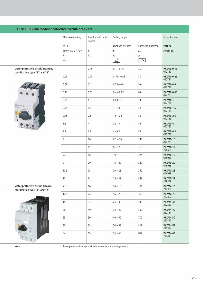
PKZM0, PKZM4 motor-protective circuit-breakers
Max. motor rating Rated uninterrupted Setting range Screw terminalscurrent
AC-3 Overload releases Short-circuit release Part no.
380 V 400 V 415 V Iu Ir Irm Article no.
P A A A
kW
– 0.16 0.1 – 0.16 2.2 PKZM0-0,16072730
0.06 0.25 0.16 – 0.25 3.5 PKZM0-0,25072731
0.09 0.4 0.25 – 0.4 5.6 PKZM0-0,4072732
0.12 0.63 0.4 – 0.63 8.8 PKZM0-0,63072733
0.25 1 0.63 – 1 14 PKZM0-1072734
0.55 1.6 1 – 1.6 22 PKZM0-1,6072735
0.75 2.5 1.6 – 2.5 35 PKZM0-2,5072736
1.5 4 2.5 – 4 56 PKZM0-4072737
2.2 6.3 4 – 6.3 88 PKZM0-6,3072738
4 10 6.3 – 10 140 PKZM0-10072739
5.5 12 8 – 12 168 PKZM0-12278486
7.5 16 10 – 16 224 PKZM0-16046938
9 20 16 – 20 280 PKZM0-20046988
12.5 25 20 – 25 350 PKZM0-25046989
15 32 25 – 32 448 PKZM0-32278489
7.5 16 10 – 16 224 PKZM4-16222350
12.5 25 16 – 25 350 PKZM4-25222352
15 32 25 – 32 448 PKZM4-32222353
20 40 32 – 40 560 PKZM4-40222354
25 50 40 – 50 700 PKZM4-50222355
30 58 50 – 58 812 PKZM4-58222394
34 65 55 – 65 882 PKZM4-63222413
Three-phase motors (approximate values for squirrel-cage rotors)
Motor-protective circuit-breakers,coordination type “1“ and “2“
Motor-protective circuit-breaker,coordination type “1“ and “2“
Note

26
Max. motor rating Rated uninterrupted Setting range Screw terminalscurrent
AC-3 Overload releases Short-circuit releases Part no.380 V 400 V 415 V Iu Ir Irm
Article no.
P A A AkW
– 0.16 0.1 – 0.16 2.2 PKZM01-0,16278475
0.06 0.25 0.16 – 0.25 3.5 PKZM01-0,25278476
0.09 0.4 0.25 – 0.4 5.6 PKZM01-0,4278477
0.12 0.63 0.4 – 0.63 8.8 PKZM01-0,63278478
0.25 1 0.63 – 1 14 PKZM01-1278479
0.55 1.6 1 – 1.6 22 PKZM01-1,6278480
0.75 2.5 1.6 – 2.5 35 PKZM01-2,5278481
1.5 4 2.5 – 4 56 PKZM01-4278482
2.2 6.3 4 – 6.3 88 PKZM01-6,3278483
4 10 6.3 – 10 140 PKZM01-10278484
5.5 12 8 – 12 168 PKZM01-12278485
7.5 16 10 – 16 224 PKZM01-16283390
9 20 16 – 20 280 PKZM01-20283383
12,5 25 20 – 25 350 PKZM01-25288893
Note Three-phase motors (approximate values for squirrel-cage rotors)
Insulated enclosures
Protection For use with Part no.type Article no.
– IP40 PKZM01+NHI-E or VHI-PKZ01+U CI-PKZ01NEMA Type 1 or A or NHI+L (2 off) 281403
With actuating diaphragm IP65 PKZM01+NHI-E or VHI-PKZ01+U CI-PKZ01-GNEMA 4X or A or NHI+L (2 off) 281404
Lockable in the Off position IP65 PKZM01+NHI-E+U or A (undervoltage CI-PKZ01-SVBNEMA 4X or shunt release)+L (2 off) 281405
Lockable in the Off position, IP65 PKZM01+NHI-E or VHI-PKZ01+U or A CI-PKZ01-SVB-Vin conjunction with VHI-PKZ01 NEMA 4X (undervoltage or shunt release)+L (2 off) 281944
With stay-put Emergency-Stop IP65 PKZM01+NHI-E or VHI-PKZ01+U or A CI-PKZ01-PVTmushroom button NEMA 4X (undervoltage or shunt release)+L (2 off) 281406
With key-release Emergency-Stop IP65 PKZM01+NHI-E or VHI-PKZ01+U or A CI-PKZ01-PVSmushroom button NEMA 4X (undervoltage or shunt release)+L (2 off) 281407
– Front IP40 PKZM01+NHI-E orVHI-PKZ01+U E-PKZ01NEMA Type 1 or A or NHI+L (2 off) 281633
With actuating diaphragm Front IP65 PKZM01+NHI-E or VHI-PKZ01+U E-PKZ01-GNEMA 4X or A or NHI+L (2 off) 281634
Lockable in the Off position Front IP65 PKZM01+NHI-E or VHI-PKZ01+U or A E-PKZ01-SVBNEMA 4X (undervoltage or shunt release)+L (2 off) 281635
Lockable in the Off position, Front IP65 PKZM01+NHI-E or VHI-PKZ01+U or A E-PKZ01-SVB-Vin conjunction with VHI-PKZ01 NEMA 4X (undervoltage or shunt release)+L (2 off) 281943
With stay-put Emergency-Stop Front IP65 PKZM01+NHI-E or VHI-PKZ01+U or A E-PKZ01-PVTmushroom button NEMA 4X (undervoltage or shunt release)+L (2 off) 281636
With key-release Emergency-Stop Front IP65 PKZM01+NHI-E or VHI-PKZ01+U or A E-PKZ01-PVSmushroom button NEMA 4X (undervoltage or shunt release)+L (2 off) 281637
Insulated enclosures for surfacemounting
Insulated enclosures for flush mounting
PKZM01 motor-protective circuit-breaker
Motor-protective circuit-breakers,coordination type “1“ and “2“
27
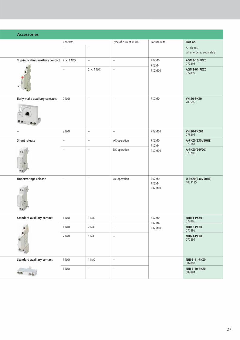
Accessories
Contacts Type of current AC/DC For use with Part no.
– – Article no.when ordered separately
Trip-indicating auxiliary contact 2 x 1 N/O – – PKZM0 AGM2-10-PKZ0
PKZM4 072898
– 2 x 1 N/C – AGM2-01-PKZ0PKZM01072899
Early-make auxiliary contacts 2 N/O – – PKZM0 VHI20-PKZ0203595
– 2 N/O – – PKZM01 VHI20-PKZ01278495
Shunt release – – AC operation PKZM0 A-PKZ0(230V50HZ)
PKZM4 073187
– – DC operation A-PKZ0(24VDC)PKZM01073200
Undervoltage release – – AC operation PKZM0 U-PKZ0(230V50HZ)PKZM4 4073135
PKZM01
Standard auxiliary contact 1 N/O 1 N/C – PKZM0 NHI11-PKZ0
PKZM4 072896
1 N/O 2 N/C – NHI12-PKZ0PKZM01072895
2 N/O 1 N/C – NHI21-PKZ0072894
Standard auxiliary contact 1 N/O 1 N/C – NHI-E-11-PKZ0082882
1 N/O – – NHI-E-10-PKZ0082884

28
Technical data basic units
PKZM01... PKZM0-... PKZM4
General
Ambient temperature
open °C –25/55 –25/55 –25/55
Terminal capacity
Solid mm2 1 x (1 – 6) 1 x (1 – 6) 1 x (1 – 50)2 x (1 – 6) 2 x (1 – 6) 2 x (1 – 35)
Flexible with ferrule mm2 1 x (1 – 6) 1 x (1 – 6) 1 x (1 – 35)2 x (1 – 6) 2 x (1 – 6) 2 x (1 – 35)
Solid or stranded AWG 18 – 10 18 – 10 14 – 2
Tightening torque, terminal screws
Main contacts Nm 1.7 1.7 3
Auxiliary contacts Nm 1 1 1
Main contacts
Rated operational voltage Ue V AC 690 690 690
Rated uninterrupted current = Iu = Ie A 16 or setting current of 32 or setting current of 65 openrated operational current overcurrent release overcurrent release 63 enclosed
or setting current of overcurrent release
Lifespan, mechanical Operations x 106 0.05 0.1 0.03
Lifespan, electric (AC-3 at 400 V) Operations x 106 0.05 0.1 0.03
Maximum operating frequency S/h 40 40 40
Releases
Temperature compensation
to IEC/EN 60947, VDE 0660 °C –5/40 –5/40 –5/40
Operating range °C –25/55 –25/55 –25/55
Setting range, overload release x Iu 0.6 – 1 0.6 – 1 0.6 – 1
Short-circuit release fixed x Iu 14 14 14
Phase-failure sensitivity IEC/EN 60947-4-1, IEC/EN 60947-4-1, IEC/EN 60947-4-1,VDE 0660 Part 102 VDE 0660 Part 102 VDE 0660 Part 102
Technical data auxiliary contacts
NHI...PKZ0 NHI-E-...PKZ0 VHI...PKZ0 AGM
Terminal capacity
Solid or flexible with ferrule mm2 0.75 – 2.5 0.75 – 1.5 0.75 – 1.5 0.75 – 2.5
Solid or stranded AWG 18 – 14 18 – 16 18 – 16 18 – 14

29
NHI-E-..-PKZ0 NHI-E-..-PKZ0
70
55
45
25
93
50
7668
45
4.5
9 26
68
45 9036
9 26
68
45 9036
18 49
68
36 45 90
5.545
45 93
4474
85
VHI...-PKZ0
80
55
45
93
50
86
68
45
VHI...-PKZ0
Rated uninterrupted current Iu
Rated conditional short-circuit current Iq IEC/EN 60947-4-1Rated ultimate short-circuit breaking capacity Icu
Rated breaking capacity Ics
IEC/EN 60947-2
1) Required back-up fuse, if the short-circuit currentexceeds the rated conditional short-circuit current of the devices (Icc � Iq).
2) Fuse (A gG/gL) to raise the switching capacity of the motor-protectivecircuit-breaker to 100 kA
N Not requiredNo upstream protective device necessary,since inherently protected range ( (100/150 kA)
PKZM, dimensions
Motor-protective circuit-breakers
PKZM0-…(+NHI-E-..-PKZ0)
Standard auxiliary contact
NHI…-PKZ0
Motor-protective circuit-breakers
PKZM01
Switching capacity with coordination type “1“ and “2“PKZM0 PKZM01
400 V 400 VIu Iq Icu Ics Iq Icu Ics
A kA kA kA A1) kA kA kA A2)
0.16 – 1 150 150 150 N 0 50 50 501.6 150 150 150 N 50 50 50 502.5 150 150 150 N 50 50 50 504 150 150 150 N 50 50 50 506.3 150 150 150 N 50 50 50 5010 150 150 150 N 50 50 50 5012 50 50 10 50 50 50 10 5016 50 50 10 50 50 50 10 5020 50 50 10 50 – – – –25 50 50 10 50 – – – –32 50 50 10 50 – – – –
Trip-indicating auxiliary contact
AGM2-…-PKZ0
Voltage release
U/A-PKZ0
Motor-protective circuit-breaker with early-make auxiliary contact
PKZM0-…+VHI-…-PKZ0
30
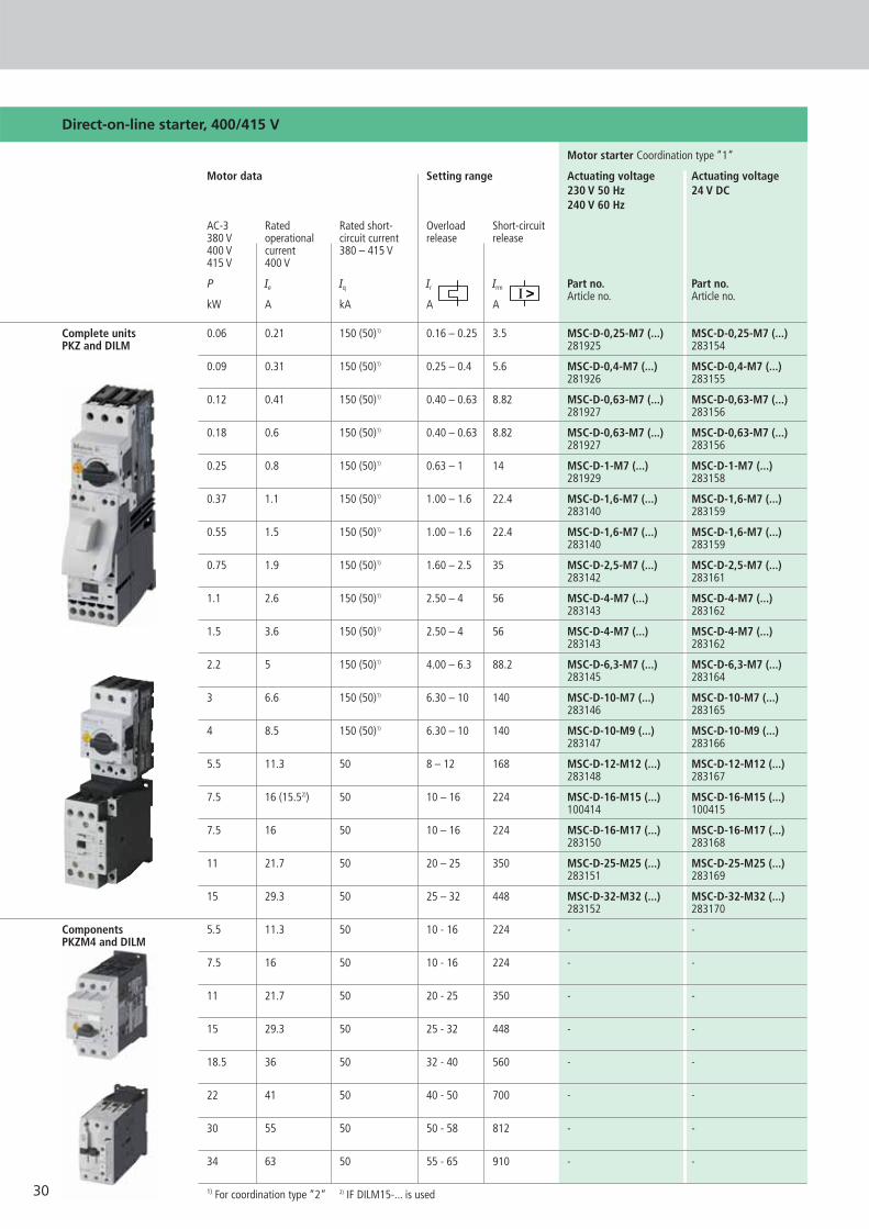
Direct-on-line starter, 400/415 V
Motor starter Coordination type “1“
Motor data Setting range Actuating voltage Actuating voltage230 V 50 Hz 24 V DC240 V 60 Hz
AC-3 Rated Rated short- Overload Short-circuit380 V operational circuit current release release400 V current 380 – 415 V415 V 400 V
P Ie Iq Ir Irm Part no. Part no.
kW A kA A AArticle no. Article no.
Complete units 0.06 0.21 150 (50)1) 0.16 – 0.25 3.5 MSC-D-0,25-M7 (...) MSC-D-0,25-M7 (...)PKZ and DILM 281925 283154
0.09 0.31 150 (50)1) 0.25 – 0.4 5.6 MSC-D-0,4-M7 (...) MSC-D-0,4-M7 (...)281926 283155
0.12 0.41 150 (50)1) 0.40 – 0.63 8.82 MSC-D-0,63-M7 (...) MSC-D-0,63-M7 (...)281927 283156
0.18 0.6 150 (50)1) 0.40 – 0.63 8.82 MSC-D-0,63-M7 (...) MSC-D-0,63-M7 (...)281927 283156
0.25 0.8 150 (50)1) 0.63 – 1 14 MSC-D-1-M7 (...) MSC-D-1-M7 (...)281929 283158
0.37 1.1 150 (50)1) 1.00 – 1.6 22.4 MSC-D-1,6-M7 (...) MSC-D-1,6-M7 (...)283140 283159
0.55 1.5 150 (50)1) 1.00 – 1.6 22.4 MSC-D-1,6-M7 (...) MSC-D-1,6-M7 (...)283140 283159
0.75 1.9 150 (50)1) 1.60 – 2.5 35 MSC-D-2,5-M7 (...) MSC-D-2,5-M7 (...)283142 283161
1.1 2.6 150 (50)1) 2.50 – 4 56 MSC-D-4-M7 (...) MSC-D-4-M7 (...)283143 283162
1.5 3.6 150 (50)1) 2.50 – 4 56 MSC-D-4-M7 (...) MSC-D-4-M7 (...)283143 283162
2.2 5 150 (50)1) 4.00 – 6.3 88.2 MSC-D-6,3-M7 (...) MSC-D-6,3-M7 (...)283145 283164
3 6.6 150 (50)1) 6.30 – 10 140 MSC-D-10-M7 (...) MSC-D-10-M7 (...)283146 283165
4 8.5 150 (50)1) 6.30 – 10 140 MSC-D-10-M9 (...) MSC-D-10-M9 (...)283147 283166
5.5 11.3 50 8 – 12 168 MSC-D-12-M12 (...) MSC-D-12-M12 (...)283148 283167
7.5 16 (15.52)) 50 10 – 16 224 MSC-D-16-M15 (...) MSC-D-16-M15 (...)100414 100415
7.5 16 50 10 – 16 224 MSC-D-16-M17 (...) MSC-D-16-M17 (...)283150 283168
11 21.7 50 20 – 25 350 MSC-D-25-M25 (...) MSC-D-25-M25 (...)283151 283169
15 29.3 50 25 – 32 448 MSC-D-32-M32 (...) MSC-D-32-M32 (...)283152 283170
Components 5.5 11.3 50 10 - 16 224 - -PKZM4 and DILM
7.5 16 50 10 - 16 224 - -
11 21.7 50 20 - 25 350 - -
15 29.3 50 25 - 32 448 - -
18.5 36 50 32 - 40 560 - -
22 41 50 40 - 50 700 - -
30 55 50 50 - 58 812 - -
34 63 50 55 - 65 910 - -
1) For coordination type “2“ 2) IF DILM15-... is used
31
Direct-on-line starter, 400/415 V
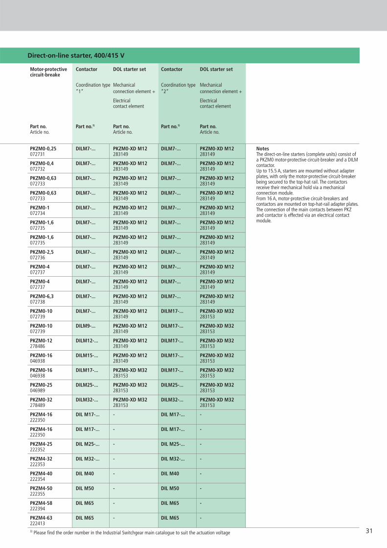
NotesThe direct-on-line starters (complete units) consist ofa PKZM0 motor-protective circuit-breaker and a DILMcontactor.Up to 15.5 A, starters are mounted without adapterplates, with only the motor-protective circuit-breakerbeing secured to the top-hat rail. The contactorsreceive their mechanical hold via a mechanical connection module.From 16 A, motor-protective circuit-breakers and contactors are mounted on top-hat-rail adapter plates.The connection of the main contacts between PKZand contactor is effected via an electrical contactmodule.
Contactor DOL starter set Contactor DOL starter set
Coordination type Mechanical Coordination type Mechanical“1“ connection element + “2“ connection element +
Electrical Electricalcontact element contact element
Part no. Part no.3) Part no. Part no.3) Part no.Article no. Article no. Article no.
PKZM0-0,25 DILM7-... PKZM0-XD M12 DILM7-... PKZM0-XD M12072731 283149 283149
PKZM0-0,4 DILM7-... PKZM0-XD M12 DILM7-... PKZM0-XD M12072732 283149 283149
PKZM0-0,63 DILM7-... PKZM0-XD M12 DILM7-... PKZM0-XD M12072733 283149 283149
PKZM0-0,63 DILM7-... PKZM0-XD M12 DILM7-... PKZM0-XD M12072733 283149 283149
PKZM0-1 DILM7-... PKZM0-XD M12 DILM7-... PKZM0-XD M12072734 283149 283149
PKZM0-1,6 DILM7-... PKZM0-XD M12 DILM7-... PKZM0-XD M12072735 283149 283149
PKZM0-1,6 DILM7-... PKZM0-XD M12 DILM7-... PKZM0-XD M12072735 283149 283149
PKZM0-2,5 DILM7-... PKZM0-XD M12 DILM7-... PKZM0-XD M12072736 283149 283149
PKZM0-4 DILM7-... PKZM0-XD M12 DILM7-... PKZM0-XD M12072737 283149 283149
PKZM0-4 DILM7-... PKZM0-XD M12 DILM7-... PKZM0-XD M12072737 283149 283149
PKZM0-6,3 DILM7-... PKZM0-XD M12 DILM7-... PKZM0-XD M12072738 283149 283149
PKZM0-10 DILM7-... PKZM0-XD M12 DILM17-... PKZM0-XD M32072739 283149 283153
PKZM0-10 DILM9-... PKZM0-XD M12 DILM17-... PKZM0-XD M32072739 283149 283153
PKZM0-12 DILM12-... PKZM0-XD M12 DILM17-... PKZM0-XD M32278486 283149 283153
PKZM0-16 DILM15-... PKZM0-XD M12 DILM17-... PKZM0-XD M32046938 283149 283153
PKZM0-16 DILM17-... PKZM0-XD M32 DILM17-... PKZM0-XD M32046938 283153 283153
PKZM0-25 DILM25-... PKZM0-XD M32 DILM25-... PKZM0-XD M32046989 283153 283153
PKZM0-32 DILM32-... PKZM0-XD M32 DILM32-... PKZM0-XD M32278489 283153 283153
PKZM4-16 DIL M17-... - DIL M17-... -222350
PKZM4-16 DIL M17-... - DIL M17-... -222350
PKZM4-25 DIL M25-... - DIL M25-... -222352
PKZM4-32 DIL M32-... - DIL M32-... -222353
PKZM4-40 DIL M40 - DIL M40 -222354
PKZM4-50 DIL M50 - DIL M50 -222355
PKZM4-58 DIL M65 - DIL M65 -222394
PKZM4-63 DIL M65 - DIL M65 -2224133) Please find the order number in the Industrial Switchgear main catalogue to suit the actuation voltage
Motor-protectivecircuit-breake

32
Reversing starter 400/415 V
Motor starter Coordination type “1“
Motor data Setting range Actuating voltage Actuating voltage230 V 50 Hz 24 V DC240 V 60 Hz
AC-3 Rated Rated short- Overload Short-circuit380 V operational circuit current release releases400 V current 380 – 415 V415 V 400 V
P Ie Iq Ir Irm Part no. Part no.
kW A kA A AArticle no. Article no.
Complete units 0.06 0.21 150 (50)1) 0.16 – 0.25 3.5 MSC-R-0,25-M7 (...) MSC-R-0,25-M7 (...)PKZ and DILM 283171 283190
0.09 0.31 150 (50)1) 0.25 – 0.4 5.6 MSC-R-0,4-M7 (...) MSC-R-0,4-M7 (...) 283172 283191
0.12 0.41 150 (50)1) 0.40 – 0.63 8.82 MSC-R-0,63-M7 (...) MSC-R-0,63-M7 (...) 283173 283192
0.18 0.6 150 (50)1) 0.40 – 0.63 8.82 MSC-R-0,63-M7 (...) MSC-R-0,63-M7 (...) 283173 283192
0.25 0.8 150 (50)1) 0.63 – 1 14 MSC-R-1-M7 (...) MSC-R-1-M7 (...) 283175 283194
0.37 1.1 150 (50)1) 1.00 – 1.6 22.4 MSC-R-1,6-M7 (...) MSC-R-1,6-M7 (...) 283176 283195
0.55 1.5 150 (50)1) 1.00 – 1.6 22.4 MSC-R-1,6-M7 (...) MSC-R-1,6-M7 (...) 283176 283195
0.75 1.9 150 (50)1) 1.60 – 2.5 35 MSC-R-2,5-M7 (...) MSC-R-2,5-M7 (...) 283178 283197
1.1 2.6 150 (50)1) 2.50 – 4 56 MSC-R-4-M7 (...) MSC-R-4-M7 (...) 283179 283198
1.5 3.6 150 (50)1) 2.50 – 4 56 MSC-R-4-M7 (...) MSC-R-4-M7 (...) 283179 283198
2.2 5 150 (50)1) 4.00 – 6.3 88.2 MSC-R-6,3-M7 (...) MSC-R-6,3-M7 (...) 283181 283200
3 6.6 150 (50)1) 6.30 – 10 140 MSC-R-10-M7 (...) MSC-R-10-M7 (...) 283182 283201
4 8.5 150 (50)1) 6.30 – 10 140 MSC-R-10-M9 (...) MSC-R-10-M9 (...) 283183 283202
5.5 11.3 50 8 – 12 168 MSC-R-12-M12 (...) MSC-R-12-M12 (...) 283184 283203
7.5 16 (15.52)) 50 10 - 16 224 - -
7.5 16 50 10 – 16 224 MSC-R-16-M17 (...) MSC-R-16-M17 (...) 283186 283204
11 21.7 50 20 – 25 350 MSC-R-25-M25 (...) MSC-R-25-M25 (...) 283187 283205
15 29.3 50 25 – 32 448 MSC-R-32-M32 (...) MSC-R-32-M32 (...) 283188 283206
Components 5.5 11.3 50 10 - 16 224 - -PKZM4 and DILM
7.5 16 50 10 - 16 224 - -
11 21.7 50 20 - 25 350 - -
15 29.3 50 25 - 32 448 - -
18.5 36 50 32 - 40 560 - -
22 41 50 40 - 50 700 - -
30 55 50 50 - 58 812 - -
34 63 50 55 - 65 910 - -
1) For coordination type “2“ 2) IF DILM15-... is used

33
Reversing starter 400/415 V
NotesThe reversing starters (complete units) consist of aPKZM0 motor-protective circuit-breaker and twoDILM contactors. Up to 12 A, starters are mountedwithout adapter plates, with only the motor-protec-tive circuit-breaker being secured to the top-hat rail.The contactors receive their mechanical hold via amechanical connection module.From 16 A, motor-protective circuit-breakers and con-tactors are mounted on top-hat-rail adapter plates.The connection of the main contacts between PKZand contactor is effected via an electrical contactmodule.Complete units with mechanical interlock, starters up to 12 A also with electrical interlock.
Contactor DOL starter set Contactor DOL starter set
Coordination type Mechanical Coordination type Mechanischer“1“ connection element + “2“ connection element +
Electrical Electricalcontact element contact element
Part no. Part no.3) Part no. Part no.3) Part no.Article no. Article no. Article no.
PKZM0-0,25 2 X DILM7-01 PKZM0-XR M12 2 x DILM7-01 PKZM0-XR M12072731 283185 283185
PKZM0-0,4 2 x DILM7-01 PKZM0-XR M12 2 x DILM7-01 PKZM0-XR M12072732 283185 283185
PKZM0-0,63 2 x DILM7-01 PKZM0-XR M12 2 x DILM7-01 PKZM0-XR M12072733 283185 283185
PKZM0-0,63 2 x DILM7-01 PKZM0-XR M12 2 x DILM7-01 PKZM0-XR M12072733 283185 283185
PKZM0-1 2 x DILM7-01 PKZM0-XR M12 2 x DILM7-01 PKZM0-XR M12072734 283185 283185
PKZM0-1,6 2 x DILM7-01 PKZM0-XR M12 2 x DILM7-01 PKZM0-XR M12072735 283185 283185
PKZM0-1,6 2 x DILM7-01 PKZM0-XR M12 2 x DILM7-01 PKZM0-XR M12072735 283185 283185
PKZM0-2,5 2 x DILM7-01 PKZM0-XR M12 2 x DILM7-01 PKZM0-XR M12072736 283185 283185
PKZM0-4 2 x DILM7-01 PKZM0-XR M12 2 x DILM7-01 PKZM0-XR M12072737 283185 283185
PKZM0-4 2 x DILM7-01 PKZM0-XR M12 2 x DILM7-01 PKZM0-XR M12072737 283185 283185
PKZM0-6,3 2 x DILM7-01 PKZM0-XR M12 2 x DILM7-01 PKZM0-XR M12072738 283185 283185
PKZM0-10 2 x DILM7-01 PKZM0-XR M12 2 x DILM17-01 PKZM0-XR M32072739 283185 283189
PKZM0-10 2 x DILM9-01 PKZM0-XR M12 2 x DILM17-01 PKZM0-XR M32072739 283185 283189
PKZM0-12 2 x DILM12-01 PKZM0-XR M12 2 x DILM17-01 PKZM0-XR M32278486 283185 283189
PKZM0-16 2 x DILM15-01 PKZM0-XR M12 2 x DILM17-01 PKZM0-XR M32046938 283185 283189
PKZM0-16 2 x DILM17-01 PKZM0-XR M32 2 x DILM17-01 PKZM0-XR M32046938 283189 283189
PKZM0-25 2 x DILM25-01 PKZM0-XR M32 2 x DILM25-01 PKZM0-XR M32046989 283189 283189
PKZM0-32 2 x DILM32-01 PKZM0-XR M32 2 x DILM32-01 PKZM0-XR M32278489 283189 283189
PKZM4-16 2 X DIL M17-.. - 2 X DIL M17-.. -222350
PKZM4-16 2 X DIL M17-.. - 2 X DIL M17-.. -222350
PKZM4-25 2 X DIL M25-.. - 2 X DIL M25-.. -222352
PKZM4-32 2 X DIL M32-.. - 2 X DIL M32-.. -222353
PKZM4-40 2 X DIL M40 - 2 X DIL M40 -222354
PKZM4-50 2 X DIL M50 - 2 X DIL M50 -222355
PKZM4-58 2 X DIL M65 - 2 X DIL M65 -222394
PKZM4-63 2 X DIL M65 - 2 X DIL M65 -2224133) Please find the order number in the Industrial Switchgear main catalogue to suit the actuation voltage
Motor-protectivecircuit-breakers
34
U V W
K1M
MM1
K2M
1 3 5
642
1 3 5
642
3
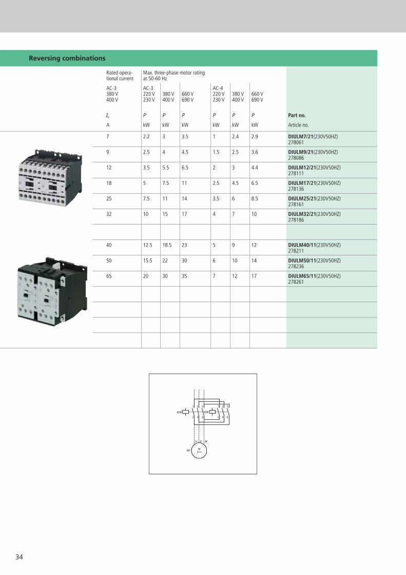
Reversing combinations
Rated opera- Max. three-phase motor ratingtional current at 50-60 Hz
AC-3 AC-3 AC-4380 V 220 V 380 V 660 V 220 V 380 V 660 V400 V 230 V 400 V 690 V 230 V 400 V 690 V
Ie P P P P P P Part no.
A kW kW kW kW kW kW Article no.
7 2.2 3 3.5 1 2.4 2.9 DIULM7/21(230V50HZ) 278061
9 2.5 4 4.5 1.5 2.5 3.6 DIULM9/21(230V50HZ)278086
12 3.5 5.5 6.5 2 3 4.4 DIULM12/21(230V50HZ) 278111
18 5 7.5 11 2.5 4.5 6.5 DIULM17/21(230V50HZ) 278136
25 7.5 11 14 3.5 6 8.5 DIULM25/21(230V50HZ) 278161
32 10 15 17 4 7 10 DIULM32/21(230V50HZ) 278186
40 12.5 18.5 23 5 9 12 DIULM40/11(230V50HZ) 278211
50 15.5 22 30 6 10 14 DIULM50/11(230V50HZ) 278236
65 20 30 35 7 12 17 DIULM65/11(230V50HZ) 278261
35
K2M
54K1M
54
53 53
K2M
22
21K1M
22
21
K1M
A1
A2K2M
A1
A2
I14
13
13
II21
22
22
21
21
220
14
K2M14
K1M14
13 13
K2M22
21K1M
22
21
K1MA1
A2K2M
A1
A2(-)N
I14
13
13
II
21
22
22
21
21
220
14
Reversing combinations
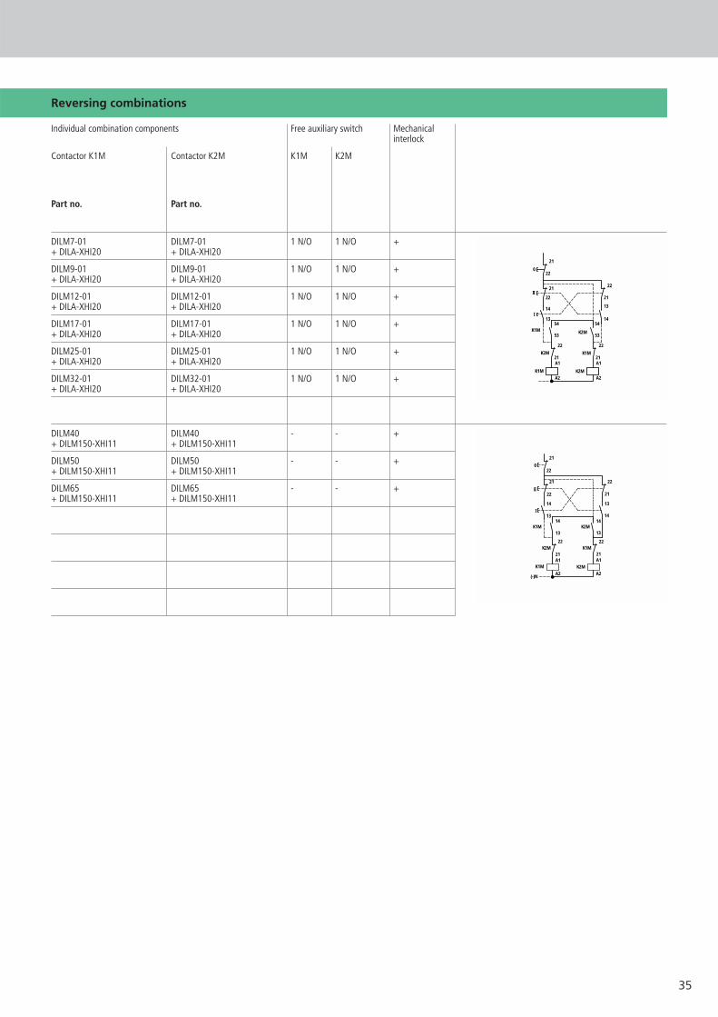
Individual combination components Free auxiliary switch Mechanicalinterlock
Contactor K1M Contactor K2M K1M K2M
Part no. Part no.
DILM7-01 DILM7-01 1 N/O 1 N/O ++ DILA-XHI20 + DILA-XHI20
DILM9-01 DILM9-01 1 N/O 1 N/O ++ DILA-XHI20 + DILA-XHI20
DILM12-01 DILM12-01 1 N/O 1 N/O ++ DILA-XHI20 + DILA-XHI20
DILM17-01 DILM17-01 1 N/O 1 N/O ++ DILA-XHI20 + DILA-XHI20
DILM25-01 DILM25-01 1 N/O 1 N/O ++ DILA-XHI20 + DILA-XHI20
DILM32-01 DILM32-01 1 N/O 1 N/O ++ DILA-XHI20 + DILA-XHI20
DILM40 DILM40 - - ++ DILM150-XHI11 + DILM150-XHI11
DILM50 DILM50 - - ++ DILM150-XHI11 + DILM150-XHI11
DILM65 DILM65 - - ++ DILM150-XHI11 + DILM150-XHI11
36
K1M1 3 5
642K5M
1 3 5
642K3M
1 3 5
642
U1V1W1
M1
3
M1
V2W2U2
A C
B
NN
21
220
K1M13
14I
14
13
K1M54
53
54K3M
53
54
53K5M
S11
K5M K3M
K1TA1
A2K1M
A1
A2
A1
A2K3M K5M
A1
A2
17
18K1T
22
21
17
28K1T
22
21
NN
21
220
K1M13
14I
14
13
K1M44
43
14K3M
13
14
13K5M
S11
K5M K3M
K1TA1
A2K1M
A1
A2
A1
A2K3M K5M
A1
A2
17
18K1T
22
21
17
28K1T
22
21
for SDAINL M12-M55
for SDAINL M70-M260
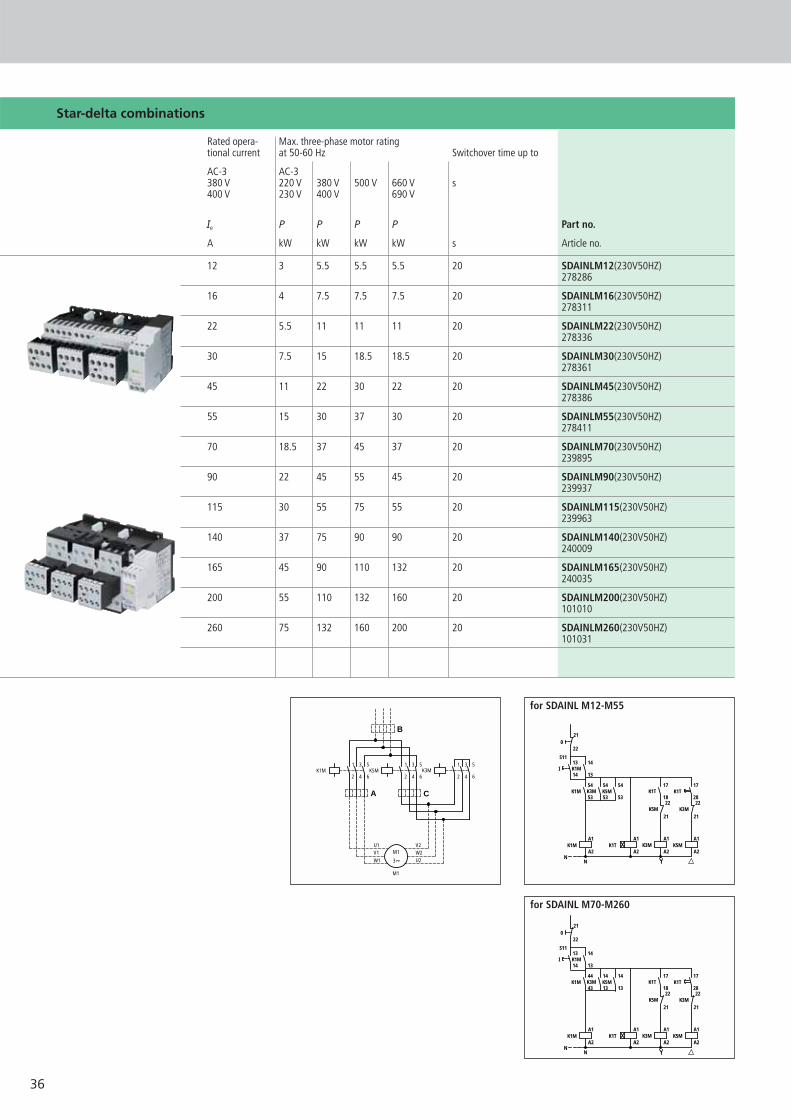
Star-delta combinations
Rated opera- Max. three-phase motor ratingtional current at 50-60 Hz Switchover time up to
AC-3 AC-3380 V 220 V 380 V 500 V 660 V s400 V 230 V 400 V 690 V
Ie P P P P Part no.
A kW kW kW kW s Article no.
12 3 5.5 5.5 5.5 20 SDAINLM12(230V50HZ) 278286
16 4 7.5 7.5 7.5 20 SDAINLM16(230V50HZ) 278311
22 5.5 11 11 11 20 SDAINLM22(230V50HZ) 278336
30 7.5 15 18.5 18.5 20 SDAINLM30(230V50HZ)278361
45 11 22 30 22 20 SDAINLM45(230V50HZ) 278386
55 15 30 37 30 20 SDAINLM55(230V50HZ) 278411
70 18.5 37 45 37 20 SDAINLM70(230V50HZ) 239895
90 22 45 55 45 20 SDAINLM90(230V50HZ)239937
115 30 55 75 55 20 SDAINLM115(230V50HZ)239963
140 37 75 90 90 20 SDAINLM140(230V50HZ)240009
165 45 90 110 132 20 SDAINLM165(230V50HZ)240035
200 55 110 132 160 20 SDAINLM200(230V50HZ)101010
260 75 132 160 200 20 SDAINLM260(230V50HZ)101031

37
Star-delta combinations
Individual combination components Free auxiliary switch
Mains contactor Delta contactor Star contactor Timing relay K1M K3M K5M
K1M K5M K3M
Part no. Part no. Part no. Part no.
DILM7-10 DILM7-01 DILM7-01 ETR4-51 1 N/O 1 N/O 1 N/O+ DILA-XHI20 + DILA-XHI20 + DILA-XHI20
DILM9-10 DILM9-01 DILM9-01 ETR4-51 1 N/O 1 N/O 1 N/O+ DILA-XHI20 + DILA-XHI20 + DILA-XHI20
DILM12-10 DILM12-01 DILM12-01 ETR4-51 1 N/O 1 N/O 1 N/O+ DILA-XHI20 + DILA-XHI20 + DILA-XHI20
DILM17-10 DILM17-01 DILM17-01 ETR4-51 1 N/O 1 N/O 1 N/O+ DILA-XHI20 + DILA-XHI20 + DILA-XHI20
DILM25-10 DILM25-01 DILM17-01 ETR4-51 1 N/O 1 N/O 1 N/O+ DILA-XHI20 + DILA-XHI20 + DILA-XHI20
DILM32-10 DILM32-01 DILM25-01 ETR4-51 1 N/O 1 N/O 1 N/O+ DILA-XHI20 + DILA-XHI20 + DILA-XHI20
DIL M40 DIL M40 DIL M40 ETR4-51 1 N/C 1 N/O - -+ DIL M150-XHI31 + DIL M150-XHI11 + DIL M150-XHI11
DIL M50 DIL M50 DIL M40 ETR4-51 1 N/C 1 N/O - -+ DIL M150-XHI31 + DIL M150-XHI11 + DIL M150-XHI11
DIL M65 DIL M65 DIL M40 ETR4-51 1 N/C 1 N/O - -+ DIL M150-XHI31 + DIL M150-XHI11 + DIL M150-XHI11
DIL M80 DIL M80 DIL M50 ETR4-51 1 N/C 1 N/O - -+ DIL M150-XHI31 + DIL M150-XHI11 + DIL M150-XHI11
DIL M95 DIL M95 DIL M65 ETR4-51 1 N/C 1 N/O - -+ DIL M150-XHI31 + DIL M150-XHI11 + DIL M150-XHI11
DIL M115 DIL M115 DIL M80 ETR4-51 1 N/C 1 N/O - -+ DIL M150-XHI31 + DIL M150-XHI11 + DIL M150-XHI11
DIL M150 DIL M150 DIL M80 ETR4-51 1 N/C 1 N/O - -+ DIL M150-XHI31 + DIL M150-XHI11 + DIL M150-XHI11
Overload relay settings Starting
A: IN x 0.58 ≤15 sProtection of the motor in Y and d configuration
B: IN x 1 15-40 sIn Y configuration only conditional motor protection
C: IN x 0.58 > 40 sNo motor protection in Y configuration
Timing relay setting to approx. 10 s
Main circuit:Depending on the aspired co-ordination type “1” or “2”, it is necessary to verify ifthe fusing and the incomer to the mains and delta contactor can be used together,or if they must be used separately.

38
Busbar adapter
39
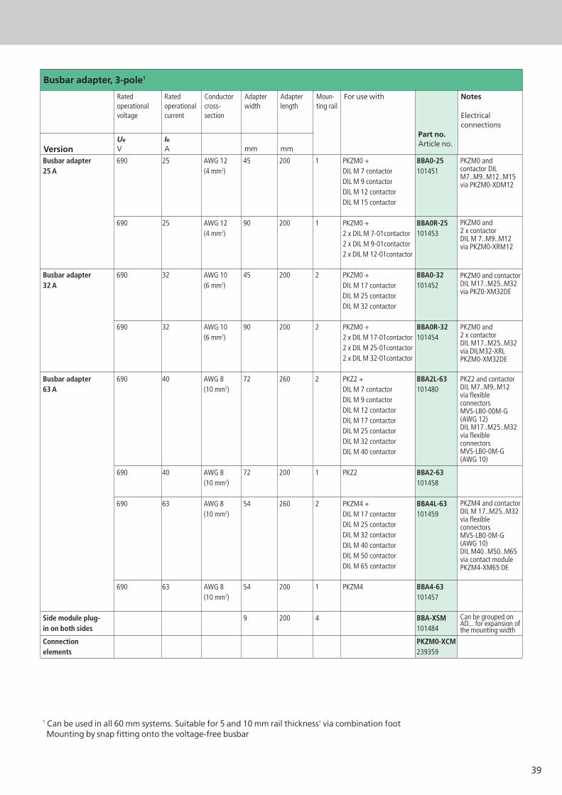
Busbar adapter, 3-pole1
Rated operationalvoltage
Rated operationalcurrent
Conductorcross-section
Adapterwidth
Adapterlength
Moun-ting rail
For use with
Part no.Article no.
Notes
Electrical connections
VersionUe
VIeA mm mm
1 Can be used in all 60 mm systems. Suitable for 5 and 10 mm rail thickness' via combination footMounting by snap fitting onto the voltage-free busbar
690 25 AWG 12 45 200 1 PKZM0 + BBA0-25(4 mm2) DIL M 7 contactor 101451
DIL M 9 contactorDIL M 12 contactorDIL M 15 contactor
690 25 AWG 12 90 200 1 PKZM0 + BBA0R-25(4 mm2) 2 x DIL M 7-01contactor 101453
2 x DIL M 9-01contactor2 x DIL M 12-01contactor
690 32 AWG 10 45 200 2 PKZM0 + BBA0-32(6 mm2) DIL M 17 contactor 101452
DIL M 25 contactorDIL M 32 contactor
690 32 AWG 10 90 200 2 PKZM0 + BBA0R-32(6 mm2) 2 x DIL M 17-01contactor 101454
2 x DIL M 25-01contactor2 x DIL M 32-01contactor
690 40 AWG 8 72 260 2 PKZ2 + BBA2L-63(10 mm2) DIL M 7 contactor 101480
DIL M 9 contactorDIL M 12 contactorDIL M 17 contactorDIL M 25 contactorDIL M 32 contactorDIL M 40 contactor
690 40 AWG 8 72 200 1 PKZ2 BBA2-63(10 mm2) 101458
690 63 AWG 8 54 260 2 PKZM4 + BBA4L-63(10 mm2) DIL M 17 contactor 101459
DIL M 25 contactor DIL M 32 contactorDIL M 40 contactorDIL M 50 contactor DIL M 65 contactor
690 63 AWG 8 54 200 1 PKZM4 BBA4-63(10 mm2) 101457
9 200 4 BBA-XSM101484
PKZM0-XCM239359
Busbar adapter 25 A
Busbar adapter32 A
Busbar adapter63 A
Side module plug-in on both sides
Connectionelements
PKZM0 and contactor DILM7..M9..M12..M15via PKZM0-XDM12
PKZM0 and 2 x contactorDIL M 7..M9..M12via PKZM0-XRM12
PKZM0 and contactorDIL M17..M25..M32via PKZ0-XM32DE
PKZM0 and 2 x contactorDIL M17..M25..M32via DILM32-XRLPKZM0-XM32DE
PKZ2 and contactorDIL M7..M9..M12via flexibleconnectorsMVS-LB0-00M-G(AWG 12)DIL M17..M25..M32via flexibleconnectorsMVS-LB0-0M-G(AWG 10)
PKZM4 and contactorDIL M 17..M25..M32via flexibleconnectorsMVS-LB0-0M-G(AWG 10)DIL M40..M50..M65via contact modulePKZM4-XM65 DE
Can be grouped onAD... for expansion ofthe mounting width

Moeller addresses worldwide:www.moeller.net/addressE-Mail: [email protected]
© 2005 by Moeller GmbHSubject to alterationsW1200+2100-7548GB MDS/DFS 02/07 Printed in the Federal Republic of Germany (03/07)Article No.: 284765
Xtra Combinations
Xtra Combinations from Moeller offers a range of productsand services, enabling the best possible combination optionsfor switching, protection and control in power distributionand automation.
Using Xtra Combinations enables you to find more efficientsolutions for your tasks while optimising the economic viability of your machines and systems.
It provides:■ flexibility and simplicity■ great system availability■ the highest level of safety
All the products can be easily combined with one another mechanically, electrically and digitally, enabling you to arriveat flexible and stylish solutions tailored to your application –quickly, efficiently and cost-effectively. The products are proven and of such excellent quality thatthey ensure a high level of operational continuity, allowingyou to achieve optimum safety for your personnel, machinery,installations and buildings.
Thanks to our state-of-the-art logistics operation, our com-prehensive dealer network and our highly motivated servicepersonnel in 80 countries around the world, you can count on Moeller and our products every time. Challenge us! We are looking forward to it!
Recommended


