Embed Size (px)
Citation preview

ZX Condensing UnitUser Manual

3
Table of Contents
Disclaimer 03
Features and Benefits 03
Nomenclature 04
Bill of Material 04
Physical Layout of the Unit 05
Product Specification
Qualified Refrigerants And Oils 06
CoreSense™ for ZX Platform Condensing Unit 06
Network Wiring 11
Installation
Condensing Unit Handling 13
Location and Fixing 14
Refrigeration Piping Installation 15
ZXL Liquid Line Insulation 15
Brazing Recommendations 15
Expansion Valve Selection 15
Electrical Connection 17
Start Up and Operation 18
Controller Initialization Message 20
Alarm Codes 22
Wiring Diagrams 25
System Start-Up and Operation Check Sheet 30
Contact Lists 32
3
ZX Platform CDUDisclaimerThank you for purchasing the ZX platform condensing unit from Emerson Climate Technologies. ZX platform CDUs are the best in class within the capacity and operating range available in the market. ZX CDU is designed to operate reliably and to deliver high operating efficiencies in medium and low temperature refrigeration applications. It also provides constant monitoring of the compressor operating conditions and displays the running or fault conditions of the CDU. ZX platform CDUs have to be installed by following the industry trade practices for its safe and reliable operation. It is assumed that the CDU is selected, installed and serviced only by professionals. The user manual does not cover good industry practices which are essential on a refrigeration equipment installation. No responsibility can be accepted for damage caused by inexperienced or inadequately trained site technicians or improper installation design.
If in doubt, please consult your local sales office, quoting unit model and serial number as shown on each unit nameplate. In case of any ambiguity, the wiring diagram supplied with each unit takes precedence over the diagram in this manual.
Introduction to ZX Platform CDUZX medium temperature, ZXD digital medium temperature and ZXL low temperature series have been highly successful and enjoys proven success with its energy savings and customer-friendly electronic features. ZX, ZXD and ZXL CDUs have been applied by several well-known end-users and chain retailers. The ZX platform is also gaining wider acceptance in the global market and specific variants have been developed and exported to the USA and to the European and Middle East markets.
Receiving your unitAll units are shipped with a holding charge of dry nitrogen inside at a low but positive pressure. Suitable labeling is prominentlydisplayed on both the unit and the packaging. Service connectors are provided on the CDU service valve for the convenient checking of the integrity of the holding charge.
It is very important to check that this holding pressure exists at the time you receive each unit from us or our authorized representatives. Please inform us or our authorized representative if the holding charge is non-existent. Failure to do so could void the claim for other related system faults at a later period.
Transit damage is essentially an insurance claim and is not covered under manufacturing defect. It is also advisable to inspect the rest of the unit for obvious physical damage and inform us or our authorized representative in case any is discovered.
ZX Platform Condensing Unit was designed based on three factors demanded by industry users:
Intelligent Store Solutions - A most innovative approach to enterprise facility management, Emerson’s Intelligent Store™ architecture integrates hardware and services, to provide retailers a single view into their entire network of facilities and understanding what facilities actually cost to operate and maintain.
The Intelligent Store architecture transforms data from store equipment and controls into actionable insights. Designed to deliver value in both new and existing stores, Emerson aims to help the retailers:
• Make better decisions on recourses investment for greatest impact • Gain accurate feedback and customized service to your specific needs • Reduce operational costs and boost the profitability at most convenience
Energy Efficiency - Utilizing Copeland Scroll™ compressor technology, variable speed fan motor, large capacity condenser coil and advanced control algorithms, energy consumption is significantly reduced. End-users can save more than 20% on annual energy costs rather than using hermetic reciprocating units.
Reliability - Combining the proven reliability of Copeland Scroll compressors with advanced electronics controller and diagnostics, equipment reliability is greatly enhanced. Fault code alerts and fault code retrieval capabilities provide information to help improve speed and accuracy of system diagnostics. Integrated electronics provide protection against over-current, over-heating, incorrect phase rotation, compressor cycling, high pressure resets, low pressure cut-outs. It can also send out a warning message to an operator when there is a liquid floodback, which can prevent critical damage on the unit.
Caution!
4 5
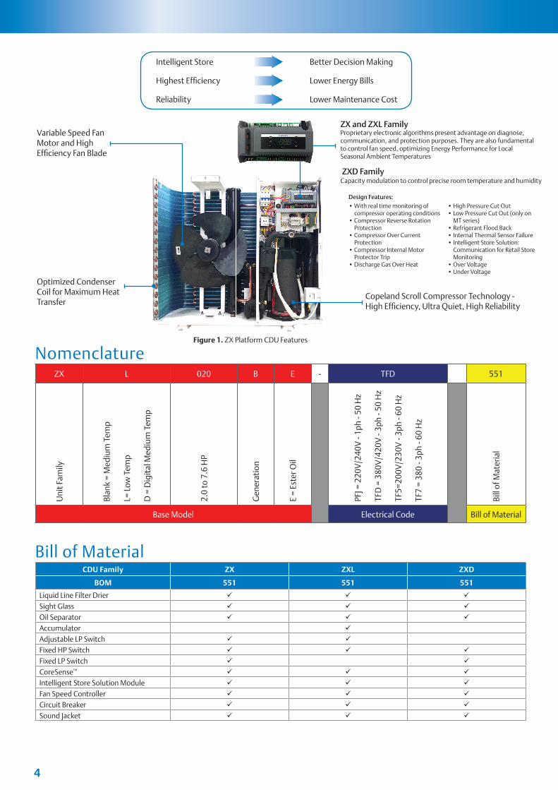
ZX and ZXL FamilyProprietary electronic algorithms present advantage on diagnose, communication, and protection purposes. They are also fundamental to control fan speed, optimizing Energy Performance for Local Seasonal Ambient Temperatures
ZXD FamilyCapacity modulation to control precise room temperature and humidity
Variable Speed FanMotor and HighEffi ciency Fan Blade
Optimized CondenserCoil for Maximum HeatTransfer
Figure 1. ZX Platform CDU Features
Design Features:• With real time monitoring of compressor operating conditions• Compressor Reverse Rotation Protection• Compressor Over Current Protection• Compressor Internal Motor Protector Trip• Discharge Gas Over Heat
• High Pressure Cut Out• Low Pressure Cut Out (only on MT series)• Refrigerant Flood Back• Internal Thermal Sensor Failure• Intelligent Store Solution: Communication for Retail Store Monitoring• Over Voltage• Under Voltage
Copeland Scroll Compressor Technology - High Effi ciency, Ultra Quiet, High Reliability
Intelligent Store
Highest Effi ciency
Reliability
Better Decision Making
Lower Energy Bills
Lower Maintenance Cost
Nomenclature
Bill of Material
ZX L 020 B E - TFD 551
Uni
t Fam
ily
Blan
k =
Med
ium
Tem
p
L= L
ow T
emp
D =
Dig
ital
Med
ium
Tem
p
2.0
to 7
.6 H
P
Gen
erat
ion
E =
Este
r Oil
PFJ =
220
V/2
40V
- 1p
h - 5
0 H
z
TFD
= 3
80V
/420
V -
3ph
- 50
Hz
TF5=
200V
/230
V -
3ph
- 60
Hz
TF7
= 38
0 - 3
ph -
60 H
z
Bill
of M
ater
ial
Base Model Electrical Code Bill of Material
CDU Family ZX ZXL ZXD
BOM 551 551 551
Liquid Line Filter Drier
Sight Glass
Oil Separator
Accumulator
Adjustable LP Switch
Fixed HP Switch
Fixed LP Switch
CoreSense™
Intelligent Store Solution Module
Fan Speed Controller
Circuit Breaker
Sound Jacket

4 5
Physical Layout of the UnitThe following figures give an introduction to the physical layout of the ZX Platform CDU
CoreSense™ ControllerModulePower Isolation Switch
Compressor Contactor
Cable Channel
Transformer
Customer Connection Terminal Block
Figure 2. CoreSense™ and other components in ZX Platform CDU
Figure 3. Major components of ZX Platform CDU
Figure 4. CoreSense™ and Intelligent Store Module Layout
CoreSense™
Scroll Compressor
Adjustable LP Controller
Accumulator
Oil Separator (Optional in MT CDU)
Liquid Receiver
Liquid Filter Drier
Suction and Liquid Service Valve
Receiver Out Service ValveCompressor Oil Sight Glass
Liquid Sight Glass/Moisture Indicator

6 7
Product SpecificationFor application envelope, envelope varies according to applications and refrigerants. Please refer to ZX platform product catalogue, product manual, or Copeland™ Brand Products Selection Software.
LED Descriptions
CoreSense™ for ZX Platform Condensing Unit
Qualified Refrigerants and Oils
Refrigerant Oil
R448 / R449 / R407F / R404A / R507 / R134a / R22
Emkarate RL 32 3MAFMobil EAL Artic 22 CC
ZX ZXD ZXL
ModelBOM
ModelBOM
ModelBOM
551 ALL ALL
ZX020BE 1.68 ZXL020BE 1.06
ZX025BE 1.83 ZXL025BE 1.06
ZX030BE 1.83 ZXL030BE 1.06
ZXL035BE 1.74
ZX040BE 2.33 ZXD040BE 1.74 ZXL040BE 1.74
ZX050BE 2.33 ZXD050BE 2.27 ZXL050BE 1.74
ZX060BE 2.16 ZXD060BE 2.27 ZXL060BE 2.27
ZX075BE 2.16 ZXD075BE 2.27 ZXL075BE 2.27
ZX076BE 2.16
Oils are pre-charged in both compressor and oil separator. Total oil volume (liter) for each unit is shown in the table below:
LED Status Description
1ON Compressor1 is running
Flashing Compressor1 is ready to start
2ON Compressor2 is running
Flashing Compressor2 is ready to start
ON Condensing fan is running
ON Digital compressor is unloading
ON Display with °C
Flashing Programmable mode
LED Status Description
ON Browsing the service menu
Flashing Browsing the fast access menu
!ON A new alarm happened
Flashing Browsing the alarm menu
! ON An alarm is occurring
ON Liquid line solenoid valve on
- Reserved

6 7
Keyboard Descriptions - Single Button
Keyboard Descriptions - Combined Buttons
Controller Display Upon Start-up
Set Display target set point; In programming mode, select a parameter or confirm an operation.
Start ResetHold for 5 seconds to reset any lockouts if the current state of the controller allows for it to be reset.
UpEnter the fast access menu; In programming mode, browse the parameter codes or increases the displayed value.
Down In programming mode it browses the parameter codes or decreases the displayed value.
Service Enter the service and alarm menu.
DefrostHold for 3 seconds to start a manual defrost or terminate an active defrost.(Not available at the moment).
Step Action Phenomenon and Description
1 Power on controller All LEDs will light up for 3 seconds.
2 Firmware version will be displayed for 3 seconds.
3 Parameter setting file (bin file) identifier will be displayed for 3 seconds.
4Normal display (actual suction temperature will be displayed on ZXD unit, condensing temperature will be displayed on ZX/ZXL unit)
+ Press and hold for about 3 seconds to lock (Pon) or unlock (PoF) the keyboard.
+ Pressed together to exit programming mode or menu; under rtC and Par, this combination allows the user to go back to previous level.
+ Pressed together for 3 seconds allows access to first level of programming mode.
+ Pressed together for 3 seconds allows access to EXV manual setting.

8 9
ZXD Unit Setting Point Modification
Pr1 parameter (1st level) Browse and Modification
Step Action Phenomenon and Description
1 Press“ ” > 3 seconds Press SET button for 3 seconds, the measurement units (°C ) will flash together.
2 Press “ ” or “ ” Modify the number
3 Press “ ”Press“SET” to confirm, the number will flash for 2 seconds (or wait for about 10 second to confirm)
Step Action Phenomenon and Description
1 Press “ ” + Enter menu to select “PAr” (parameter) or “rtC”
2 Press “ ” or “ ” Select “PAr (parameter)”
3 Press “ ” Confirm, select, and browse Pr1 parameters
4 Press “ ” or “ ” Browse Pr1 parameters
5 Press “ ” View the actual number of the Pr1 parameters
6 Press “ ” or “ ” Modify the actual number of the Pr1 parameters
7 Press “ ”Press“SET” : The number will flash for 3 seconds and confirm the modification; Will go to the next Pr1 parameter
8 Press “ ” + Exit (or exit automatically after waiting for 120 seconds)

8 9
Quick Access Menu Browse - Sensors Status and Actual Values
Access Alarm Code (Maximum of 50 record)
Step Action Phenomenon and Description
1 Press “ ” Enter quick access menu, will display“P1P”(Press “Up” or “Down” to view other sensors
2 Press “ ” View the actual value of “P1P”
3 Press “ ” Change to next Sensor code
4 Press “ ” + “ ” Exit (or exit automatically after waiting for 60 seconds)
Sensor Code and Values Descriptions(“nP”, “noP”, or“nA” mean that the sensor does not exist; “Err” means that the sensor
fails, out of range, disconnected, or does not configure correctly)
• P1P : suction pressure sensor (only for ZXD unit)• P2t : condensing temperature ((mid-coil) sensor • P2P : pressure sensor (not used)• P3 : discharge line temperature sensor • P4 : PHE vapor inlet temperature sensor • P5 : PHE vapor outlet temperature sensor• P6 : ambient temperature sensor • P7 : temperature sensor (not used)• SH : PHE superheat• oPP : EXV opening step• LLS : the status of liquid line solenoid valve• Std : Condensing temperature setting point• Aoo : The percentage of the analog output• dSo : percentage of the PWM output driving the valve of the Digital Scroll compressor• Lt : min cold room temperature (may not be available)• Ht : max cold room temperature (may not be available)• HM : Time menu
Step Action Phenomenon and Description
1 Press “ ” Display “SEC”
2 Press “ ” Display “A01”
3 Press “ ” Display alarm code in “A01”
4 Press “ ” Display “A02”
5 Press “ ” Display alarm code in “A02”
6 …
7 Press “ ” + “ ” Exit (or exit automatically after waiting for 15 seconds)

10 11
Exact Timing of the Alarm
Upload the Program from the Controller to Hot-Key
Step Action Phenomenon and Description
1 Press “ ” Display “SEC”
2 Press “ ” Display “A01”
3 Press “ ” Display alarm code in “A01”
4 Press “ ” Display “Hr”
5 Press “ ” Display the alarm exact timing: hour
6 Press “ ” Display “Min”
7 Press “ ” Display the alarm exact timing: minute
8 Press “ ” Display “dAy”
9 Press “ ” Display the alarm exact timing: day
10 Press “ ” Display “Mon”
11 Press “ ” Display the alarm exact timing: month
12 Press “ ” Display “yEA”
13 Press “ ” Display the alarm exact timing: year
14 Press “ ” + “ ” Exit (or exit automatically after waiting for 15 seconds)
Step Action Phenomenon and Description
1Insert Hot-Key when the
controller is ON
2 Press “ ”The “uPL” message appears followed a by a flashing “End” label(Note: if display “Err”, it means it fails to upload program to Hot-Key.Please restart the process.)
3 Press “ ” “End”will stop flashing
4Turn-off the controller and remove Hot-Key
5 Turn-on the controller

10 11
ZX CDU Connected to XWEB300DZX CDU connected to the Dixell XWEB300D with the Intelligent Store Solution Module using RS485 ModBUS.
Connect the ZX CDU to the ModBUS network as shown in Figure 5. Connect the network cable to the three-terminal connector on the XWEB300D port that has been configured as ModBUS port (COM 12, 13, 14).
Connect port “13” of XWEB300D to port “D0485 +” of CoreSense™ and port “12” of XWEB300D to port “D1485 -” of CoreSense for RS485 communication.
Network Wiring
Dixell XWEB300D Serial Address - Wiring • Connect to the ModBUS network using cable with 2 or 3 shielded wires, minimum section 0.5mm2
(e.g. BELDEN8772) • Do not connect shield to ground. • Do not connect the “Gnd” terminal. • Remember to draw a map of the line. This will help you to find an error if something is wrong. • RS485 devices are polarity sensitive.
Figure 6. Correct Network Wiring Figure 7 . Incorrect Network Wiring
Figure 5. XWEB300D Connected to the Intelligent Store Solution Module
Download the Program from Hot-Key to Controller
Step Action Phenomenon and Description
1 Turn-off the controller
2 Insert Hot-Key
3 Turn-on the controllerThe “doL” message will blink followed a by a flashing “End” label (Note: if display “Err”, it means it fails to download program to the controller. Please restart the process.)
4 Controller will restart working with the new parameters after 10 seconds
5 Remove Hot-Key
12 13
Termination Resistor for XWEB300DIf XWEB300D is placed at the beginning or at the end of the line, please install its termination resistor by adding a jumper in position 2 (JMP2 on the back side of the unit). Do not add the jumper if XWEB300D is placed in the middle of the RS485 line.
Dixell XWEB300D Configuration For CoreSenseXWEB300D is compatible with ZX CDU if XWEB has the library of ZX controller CoreSense (controller) model.
Login into XWEB• Go to Information → Information• If this is not present, follow the steps below.
Open Dixell website http://www.dixell.com/xweb300d-xweb500-xweb500d/eng/, then login (register required)• Go to Support → System sw update → XWEB300D XWEB500 XWEB500D• Download the upgrade package With your web-browser, login into XWEB• Go to Information → System Update menu
Provide the XW5 patch file
Once file has been selected wait until the upgrade procedure ends (XWEB reboots)Verify the installation ended successfully by checking into the menu• Go to Information → Information for string
Log in again and set up the ZX CDU
• Go to Configuration → Devices drop-down menu• Go to Actions → New• Enter device name in the Name field (e.g. ZX CDU)• Select “XCM25D” in the Model field• Enter the ModBUS address in the RS 485 address field ∙ Refer to setting of parameter “t01” in pr2 level in CoreSense™ (default setting is “1”)• Click New

12 13
InstallationCopeland ZX condensing units are delivered with a holding charge of neutral gas. The condensing unit should be located in such a place to prevent any dirt, plastic bag, leaves or papers from covering the condenser and its fins. The unit must be installed without restricting the airflow. A clogged condenser will increase the condensing temperature, thus reduce the cooling capacity, and lead to a high-pressure switch tripping. Clean the condenser fins on a regular basis.
ZX ZXD ZXL
Model Weight (kg) Model Weight (kg) Model Weight (kg)
ZX020BE 76 ZXD040BE2 104 ZXL020BE 79
ZX025BE 79 ZXD050BE3 112 ZXL025BE 81
ZX030BE 79 ZXD060BE4 114 ZXL030BE 81
ZX040BE1 91 ZXD075BE5 122 ZXL035BE 93
ZX050BE 108 ZXL040BE 93
ZX060BE 112 ZXL050BE 106
ZX075BE 118 ZXL060BE 116
ZX076BE 121 ZXL075BE 121
Net Weight
Notes:1 100 kg for models under 60 Hz TF5/7 and 50 Hz PFJ2 109 kg for models under 60 Hz TF73 117 kg for models under 60 Hz TF74 121 kg for models under 60 Hz TF75 127 kg for models under 60 Hz TF7
Transport and StorageMove ZX/ZXD/ZXL unit only with appropriate mechanical or handling equipment according to weight. Keep in the upright position. Do not stack single boxes on top of each other without pallet in any case. Keep the packaging dry at all times.
Condensing Unit Handling

14 15
840
500
500300
300500 352
7070
2390
172
424
Power Supply Hole
Suction Service Valve
Liquid Service Valve
388
110580
2 HOLESØ15MM DIA
2-R7.5MM GROOVE
1029
21
1242
17290
500 300
300
500352
70 70
1029
23
424
94Liquid Service Valve
Suction Service Valve
Power Supply Hole
388
110580
2 HOLESØ15MM DIA
2-R7.5MM GROOVE
500
21
Fixing dimensions and distances - Single fan unit
Fixing dimensions and distances - Dual fan unit
Location and FixingThe unit should always be installed in a location that ensures clean air flow. It is recommended that a clearance of 300 mm from the wall (or the next unit) be maintained from the unit’s left and rear panels whereas a clearance of 500 mm must be maintained from the unit’s right, top and front panels (seen facing the front of the unit). Both service access and airflow have been considered in making these recommendations. Where multiple units are to be installed in the same location, the contractor needs to consider each individual case carefully. There can be many variations of unit quantities and available space and it is not the intention of this manual to go over these. Ideally, the unit should be mounted on a solid concrete slab with anti-vibration pads between unit feet and concrete. However the ZX condensing unit has also been designed for wall mounting on suitable brackets. Wall mounting brackets are not included. Another factor to consider in finding a good installation site is the direction of the prevailing wind. For example if the air leaving the condenser faces the prevailing wind, the air flow through the condenser can be impeded, causing high condensing temperatures ultimately resulting in reducing unit life. A baffle is a remedy for this situation.

14 15
Refrigeration Piping InstallationAll interconnecting pipes should be of refrigeration grade, clean, dehydrated and must remain capped at both ends until installation. Even during installation, if the system is left for any reasonable period of time (say two hours), pipes should be re- capped to prevent moisture and contaminants from entering the system.
Do not assume that the service connection sizes on the unit (at the service valves) are the correct size to run your interconnecting refrigeration pipes. The service valve sizes have been selected for convenience of installation and in some cases (larger units) these may be considered too small. However for the very short pipe run within our units, these service connection sizes are adequate. All interconnecting pipes should be sized to satisfy the duty required.
Usually the suction line is insulated, but the liquid line is not. However the liquid line can pick up additional heat from the ambient and adversely affect the sub-cooling desirable for the liquid refrigerant before it enters the expansion valve.
The pipe should be sized to ensure optimum performance and good oil return. The sizing must also take into account the full capacity range through which this particular unit will need to operate.
Pipe runs should be kept as short as possible, using the minimum number of directional changes. Use large radius bends and avoid trapping of oil and refrigerant. This is particularly important for the suction line. The suction line should ideally slope gently towards the unit. Recommendation slope is 1/200~1/250. P traps, double risers and reduced pipe diameters may be required for suction lines where long vertical risers cannot be avoided. All pipes should be adequately supported to prevent sagging which can create oil traps.The recommended pipe clamp support distance is shown in the table.
ZXL Liquid Line InsulationZXL liquid line should be insulated with a 19 mm insulation thickness. Temperature could be as low as –15°C.
Brazing RecommendationsMaintain a flow of oxygen-free nitrogen through the system at a very low pressure during brazing. Nitrogen displaces the air and prevents the formation of copper oxides in the system. If copper oxidization is allowed to form, the copper oxide material can later be swept through the system and block screens such as those protecting capillary tubes, thermal expansion valves, and accumulator oil return holes. This minimizes any entry of contaminants and moisture.
• Remove the liquid line connection cap.
• Then remove the suction connection cap.
• Open both valves midway. Care should be taken to avoid the holding charge from releasing too quickly.
• Be sure tube fitting inner diameter and tube outer diameter are clean prior to assembly.
• Since both tubes are extended from the condensing unit housing, we recommend insulating the housing by using a wet cloth on the copper tubing.
• Recommended brazing materials: a copper / phosphorous or copper / phosphorous / silver alloy rod should be used for joining copper to copper whereas to join dissimilar or ferric metals, use a silver alloy rod, either flux coated or with a separate.
• Use a double tip torch.
Tube SizeMax distance between
2 clamp support
12.7mm (1/2 inch) 1.20 m
16.0mm (5/8 inch) 1.50 m
22.0mm (7/8 inch) 1.85 m
28.5mm (1 1/8 inch) 2.20 m
End of Tube
During brazing protect housing with damp cloth
During brazing pull back fire insulation
OUTSIDE INSIDE UNIT
Expansion Valve Selection for Low Ambient ApplicationFor systems expected to operate in varying ambient conditions – namely summer and winter temperatures – the expansion valve (TXV or EXV) sizing should take into consideration the maximum expected saturated condensing temperature at high ambient conditions (summer) and the minimum expected saturated condensing temperature, set at -25°C, during low ambient conditions (winter).
The chosen expansion valve’s operating capacities should be well within these limits to ensure satisfactory system performance.
In the event that different expansion valves come up for the two conditions, the valve for low ambient condition should beselected. This means that at higher ambient, the valve will be oversized. However, if the valve at the high ambient is selected, itmay be too small during low ambient condition.

16 17
Thermal Expansion Valve Selection Guide
Selection at 30K Subcooling
R22 R404A R407A/F
Tevap = -5°CTamb = 43°C
50Hz Body - TIE-HW (802421)
60Hz Body - TIE-HW (802421)
50Hz Body - TIE-SW (802460)
60Hz Body - TIE-SW (802460)
50Hz Body - TIE-NW (802436)
60Hz Body - TIE-NW (802436)
ZX Model Orifice Orifice Orifice Orifice Orifice Orifice
ZX020BE TIO-002 (800535) TIO-002 (800535) TIO-002 (800535) TIO-003 (800536) TIO-001 (800534) TIO-002 (800535)
ZX025BE TIO-002 (800535) TIO-002 (800535) TIO-003 (800536) TIO-002 (800535)
ZX030BE TIO-002 (800535) TIO-003 (800536) TIO-003 (800536) TIO-004 (800537) TIO-002 (800535) TIO-003 (800536)
ZX040BE TIO-003 (800536) TIO-003 (800536) TIO-004 (800537) TIO-004 (800537) TIO-003 (800536) TIO-003 (800536)
ZX050BE TIO-003 (800536) TIO-004 (800537) TIO-005 (800538) TIO-005 (800538) TIO-004 (800537) TIO-004 (800537)
ZX060BE TIO-004 (800537) TIO-004 (800537) TIO-005 (800538) TIO-006 (800539) TIO-004 (800537) TIO-004 (800537)
ZX075BE TIO-004 (800537) TIO-004 (800537) TIO-006 (800539) TIO-006 (800539) TIO-004 (800537) TIO-004 (800537)
ZX076BE TIO-004 (800537) TIO-006 (800539) TIO-004 (800537)
R22 R404A R407A/F
Tevap = -5°CTamb = 43°C
50Hz Body - TIE-HW (802421)
60Hz Body - TIE-HW (802421)
50Hz Body - TIE-SW (802460)
60Hz Body - TIE-SW (802460)
50Hz Body - TIE-NW (802436)
60Hz Body - TIE-NW (802436)
ZXL Model Orifice Orifice Orifice Orifice Orifice Orifice
ZXL020BE TIO-001 (800534) TIO-001 (800534) TIO-001 (800534) TIO-001 (800534) TIO-001 (800534) TIO-001 (800534)
ZXL025BE TIO-001 (800534) TIO-001 (800534) TIO-001 (800534) TIO-001 (800534) TIO-001 (800534) TIO-001 (800534)
ZXL030BE TIO-001 (800534) TIO-001 (800534) TIO-001 (800534) TIO-002 (800535) TIO-001 (800534) TIO-001 (800534)
ZXL035BE TIO-001 (800534) TIO-001 (800534) TIO-001 (800534) TIO-002 (800535) TIO-001 (800534) TIO-002 (800535)
ZXL040BE TIO-001 (800534) TIO-002 (800535) TIO-001 (800534) TIO-003 (800536) TIO-002 (800535) TIO-002 (800535)
ZXL050BE TIO-002 (800535) TIO-002 (800535) TIO-001 (800534) TIO-003 (800536) TIO-002 (800535) TIO-002 (800535)
ZXL060BE TIO-002 (800535) TIO-003 (800536) TIO-003 (800536) TIO-003 (800536) TIO-002 (800535) TIO-003 (800536)
ZXL075BE TIO-002 (800535) TIO-003 (800536) TIO-003 (800536) TIO-003 (800536) TIO-003 (800536) TIO-003 (800536)
R134a
Tevap = -5°CTamb = 43°C
50Hz Body - TIE-MW (802446)
60Hz Body - TIE-MW (802446)
ZX Model Orifice Orifice
ZX020BE TIO-002 (800535) TIO-002 (800535)
ZX030BE TIO-003 (800536) TIO-003 (800536)
ZX040BE TIO-003 (800536) TIO-004 (800537)
ZX050BE TIO-004 (800537) TIO-004 (800537)
ZX060BE TIO-004 (800537) TIO-005 (800538)
ZX075BE TIO-004 (800537) TIO-005 (800538)
Note: For the ZXD Units, we recommend using Alco Electronic Expansion Valves (EXV). The selection of the EXV will depend on the load profile on the ZXD Unit. Please contact your local Emerson Climate Technologies office for assistance on selection.

16 17
Electrical ConnectionPower SupplyThe ZX condensing unit electrical connection to the power supply must be made by qualified technicians, who should refer to the electrical diagrams located inside the electric connection panel. The units are designed for below power supply at ± 10% voltage tolerance. The circuit breaker must be switched off before opening the front panel.
Electrical WiringBefore commissioning, ensure that neutral “N” wire is connected to the terminal block (“N” furthest to the right). After proper connection of the ZX condensing unit, the control LED on the power board and control board will light up. For more details, see wiring diagrams. Customers’ wire size needs to be selected to allow for the maximum operation current of each unit.
BOM Codes HZ Phase Voltages
ALL PFJ 50 1 220/240
ALL TFD 50 3 380/420
ALL TF7 60 3 380
551 TF5 60 3 230
Caution! Unit should be powered on at all times except during service. Failure to do so can result in component failure.
Unit Unit MOC (A)
ZX020BE-TFD 5.7
ZX030BE-TFD 8.0
ZX040BE-TFD 11.1
ZX050BE-TFD 14.4
ZX060BE-TFD 14.7
ZX075BE-TFD 15.6
ZX076BE-TFD 15.6
ZX020BE-TF5 11.3
ZX030BE-TF5 15.4
ZX040BE-TF5 20.7
ZX050BE-TF5 24.6
ZX060BE-TF5 28.7
ZX075BE-TF5 27.4
ZX020BE-TF7 8.3
ZX030BE-TF7 8.3
ZX040BE-TF7 12.2
ZX050BE-TF7 15.2
ZX060BE-TF7 15.3
ZX075BE-TF7 17.2
ZX020BE-PFJ 13.6
ZX025BE-PFJ 13.2
ZX030BE-PFJ 17.2
ZX040BE-PFJ 24.3
Unit Unit MOC (A)
ZXL020BE-TFD 6.5
ZXL025BE-TFD 6.9
ZXL030BE-TFD 7.5
ZXL035BE-TFD 8.3
ZXL040BE-TFD 10.0
ZXL050BE-TFD 13.5
ZXL060BE-TFD 15.3
ZXL075BE-TFD 16.2
ZXL020BE-TF5 12.4
ZXL025BE-TF5 13.5
ZXL030BE-TF5 15.5
ZXL035BE-TF5 15.7
ZXL040BE-TF5 23.2
ZXL050BE-TF5 25.7
ZXL060BE-TF5 31.2
ZXL075BE-TF5 33.4
ZXL020BE-TF7 7.3
ZXL025BE-TF7 7.2
ZXL030BE-TF7 8.4
ZXL035BE-TF7 9.7
ZXL040BE-TF7 12.7
ZXL050BE-TF7 14.8
ZXL060BE-TF7 18.1
ZXL075BE-TF7 18.6
Unit Unit MOC (A)
ZXD040BE-TFD 9.5
ZXD050BE-TFD 12.9
ZXD060BE-TFD 13.0
ZXD075BE-TFD 15.6
ZXD076BE-TFD 15.6
ZXD040BE-TF7 11.5
ZXD050BE-TF7 14.2
ZXD060BE-TF7 16.2
ZXD075BE-TF7 17.6

18 19
Start Up and OperationNextGen ZX Start-Up GuideBefore commissioning, ensure that all valves on the condensing unit are fully opened.
For ZXL Condensing Units, Liquid Line MUST be insulated – atleast ½” minimum insulation .
Careful selection of Expansion Valves due to the increased sub cooling effect by the Vapor Injection plate heat exchanger.SEE page 16 of this manual
Leak CheckThe unit has been leak tested and QA approved from the factory. However, due to handling and shipping the entire refrigeration system must be tested for leaks. Failure to carry out leak test can result to undesirable system performance.
Step-by-step:1. Open both the liquid and suction service valves.2. Ensure the solenoid valve is energized and open.3. Pressurize the system to 300 psig/21 Bar maximum with dry nitrogen.4. Allow dry nitrogen to reach all parts of the system.5. Check all joints and components using soap/bubble test or with an electronic leak detector.6. Wait for atleast an hour to ensure the system is holding the pressure and is found to be leaked-proof, if the system loses any pressure over the course of 30 minutes to 1 hour, then it is a sure indication that the system is leaking
If leak has been detected somewhere on the system, relief the pressure and repair the leak. For an effective installation, the system must be leak tight.
System EvacuationEvacuating a refrigeration system serves two primary objectives: (1) remove noncondensables and (2) remove water vapor or dehydrate the system.
Air and moisture are detrimental to system operation. The successful long-term operation of the system depends on thoroughly conditioning them before charging with refrigerant and the losses associated with improper evacuation erodes system efficiency as well as costly for the installers.
A 2-stage vacuum pump along with a micron gauge is recommended in performing evacuation. The quality of vacuum is not determined by time – a micron gauge must be used since it is the only device that accurately reads the vacuum pressure during the evacuation process.
REMINDER: Do not use the system compressor as a vacuum pump and do not operate the compressor while the system is in vacuum.
Emerson Climate Technologies recommends Triple Evacuation Process (best practice) to be implemented on all our installations.
Step-by-step:1. Open both the liquid and suction service valves.2. Ensure the solenoid valve is energized and open.3. Connect vacuum pump to the liquid and suction service valves.4. Start the vacuum pump and then open the service valves.5. Perform triple evacuation process as follows: i. Vacuum until a pressure of 1,500 microns is reached — at which time the vacuum should be broken with the refrigerant to be used in the system through a drier until the system pressure rises to 2 psig ii. Repeat this process again iii. Evacuate the entire system to 500 microns
At this point, Valve Off the system, turn off vacuum pump then wait 30mins before checking the micron gauge readings: ∙ Between 500 and 1,000 microns – Evacuation is Complete! Proceed with refrigerant charging ∙ Above 1,000 but below 5,000 microns – Moisture was NOT Completely Removed. TO DO: RE-Evacuate the System until Vacuum will Hold ∙ Above 5,000 microns – Indicates System Leak or within the connections TO DO: Search for the leak & carry-out repair procedures then perform triple evacuation process again
6. The evacuation process is complete once vacuum quality is achieved. Then close the two manifold valves tightly. Close the pump main valve, and remove the vacuum pump.
KEEP IN MIND

19
Refrigerant Charging
Reminder∙ The scroll compressor design requires system charging with liquid refrigerant into the liquid line.∙ Do not vapor charge the ZX Scroll unit.
After ensuring all valves are opened and system is vacuumed properly, only then start the refrigerant charging process
Step-by-step:1. Ensure that there is no power supply to the ZX unit. The Liquid Line solenoid needs to be kept open for the charging process and this may require a temporary power feed to it.2. Connect the refrigerant cylinder to main service hose and purge line at the manifold end.3. Ensure correct orientation of the refrigerant cylinder. Follow cylinder labeling/instructions so that liquid refrigerant can be charged into the system. This will be charged through the high-pressure side of the manifold and ZX unit liquid service valve.4. The refrigerant cylinder should be weighed at this point to be able to record the final refrigerant charge. Note that the standard receiver capacity is 4.4 kg of refrigerant for single-fan units and 6.3 kg of refrigerant for dual-fan units at 80% capacity and 32°C ambient temperature (R404A).5. Now open the liquid service valve (off the back seat). With a good vacuum in the system, the refrigerant cylinder correct orientation and at ambient, you should not need to run the compressor at all.6. The compressor can then be started, and the unit continued to be charged (with liquid refrigerant through the liquid service valve). The quantity of charge should always be measured. See note.7. Turn off the unit and open the receiver outlet valve (which was almost fully closed earlier).8. The system needs to be operated down to its design evaporating temperature before you can be sure the charge is correct. It is at this point that the normal refrigeration operational checks can be carried out - such as checking the liquid line sight glass for violent bubbles and the operating pressures.
In the event that the system is still short of refrigerant, repeat from step #5 onwards.
Refrigerant charging is regarded full/complete when the operating temperature of the system has been stable for some time and the liquid line sight glass is clear.
Electrical (Power) Connections
ZX Condensing units’ uses 3-Phase Scroll compressors and can rotate in the wrong direction when starting. If this happens reverse any two phases (L1 & L3) and start again. Built-In Electrical Contactors – Requires 3-Phase Power Supply Line ONLY (as shown) NO ADDITIONAL CONNECTIONS at the ON-BOARD CONTACTORS
Maximum Compressor CycleMaximum permitted starts per hour is 10.
KEEP IN MIND
ZX CDU Field Wiring Connections: L1, L2, L3 and Neutral Line (N)

20 21
Bin Files Number Range
Step Action Phenomenon and Description
1 Press “ ” + “ ” Enter menu to select “PAr” (parameter) or “rtC”
2 Press “ ” or “ ” Select “rtC”
3 Press “ ”
“n01” , minute
“n02” , hour
“n03” , day
“n04” , month
“n05” , year (last two digits)
4 Press “ ” Display actual value
5 Press “ ” or “ ” Modify the value
6 Press “ ” Press“SET” : the value will flash for 3 second, then move to the next value
7 Press “ ” + “ ” Exit to “rtC”
8 Press “ ” + “ ” Exit to main menu (or wait for 120 seconds and exit atomically)
After installation and initial power on, it is critical to double check the parameters below.
RTC (Real Time Clock) Setting
Bin Number Range Family
1 to 200 ZX
301 to 500 ZXL
501 to 600 ZXD
800 to 806 Service Part
Step Action Phenomenon and Description
1 Power on controller All LEDs will light up for 3 seconds.
2 Firmware version will be displayed for 3 seconds.
3 Parameter setting file (bin file number) identifier will be displayed for 3 seconds.
4Normal display (actual suction temperature will be displayed on ZXD unit, condensing temperature will be displayed on ZX/ZXL unit)
Controller Initialization Message

21
Step Action Phenomenon and Description
1 Press “ ” + “ ” Enter menu to select “PAr” (parameter) or “rtC”
2 Press “ ” or “ ” Select“PAr (parameter)”
3 Press “ ” Confirm selection
4 Press “ ” or “ ” Browse to parameter C07
5 Press “ ” Confirm selection
6 Press “ ” or “ ” Select refrigerant to be used
7 Press “ ” The number will flash for 3 seconds and confirm the refrigerant selection
8 Press “ ” + “ ” Exit (or exit automatically after waiting for 120 seconds)
Refrigerants
Step Action Phenomenon and Description
1 Press “ ” > 3 secondsPress “ ” button for more than 3 seconds, the measurement units (°C ) will flash together.
2 Press “ ” or “ ” Modify the number for Target Evaporating Temperature
3 Press “ ”Press “ ” to confirm, the number will flash for 2 seconds (or wait for about 10 seconds to confirm)
Evaporating Temperature (ZXD Only)

22 23
Alarm CodesLevel Descriptions
WarningUnit (including compressor) is running but some data reachunsafe area; alarm dry-contact will not close; reset automatically
AlarmUnit (including compressor) may run not with full functions; alarm dry-contact will not close; resetautomatically
Lock Unit (including compressor) stops working; alarm dry-contact will close; manual reset is needed
Diagnostics
Alarm Code
Description Possible Reason Action Reset
Hardware error
E01Suction pressure probe
failure alarm Probe failure or out of range No (ZXD Unit Only)
Automatic Reset when the probe restarts working
E02Condensing temperature
probe failure alarmProbe failure or out of range
(-40 ~ 110°C) Function: fan speedcontrol is disabled
Automatic Reset when the probe restarts working
E03Discharge temperature
probe failure alarmProbe failure or out of range
(-40 ~ 180°C)Function: discharge temperature protection is disabled
Automatic Reset when the probe restarts working
E04PHE vapor inlet temperature
probe failure alarmProbe failure or out of range
(-40 ~ 110°C)Function: PHE Superheat Control is disabled(ZXL unit only)
Automatic Reset when the probe restarts working
E05PHE vapor outlet tempera-
ture probe failure alarmProbe failure or out of range
(-40 ~ 110°C)Function: PHE Superheat Control is disabled(ZXL unit only)
Automatic Reset when the probe restarts working
E06Ambient temperature probe
failure alarmProbe failure or out of range
(-40 ~ 110°C)Related functions are disabled
Automatic Reset when the probe restarts working
E09 Current sensor 1 error alarm Out of range Related functions are disabledAutomatic Reset when the probe restarts working
E10 Current sensor 2 error alarm Out of range Related functions are disabledAutomatic Reset when the probe restarts working
E11 Voltage sensor 1 error alarm Out of range Related functions are disabledAutomatic Reset when the probe restarts working
E12 Voltage sensor 2 error alarm Out of range Related functions are disabledAutomatic Reset when the probe restarts working
E13 Voltage sensor 3 error alarm Out of range Related functions are disabledAutomatic Reset when the probe restarts working

23
Alarm Code
Description Possible Reason Action Reset
Electrical Error
E20 Missing phase alarmOne or two phases of compressor power supply lost or Voltage sensors do not work (3-ph unit only)
The compressor will be tripped Automatically with time delay
L20 Missing phase lockMissing phase alarm happened frequently
The compressor will be tripped and the unit will be locked
Press “Start” >5 sec or manually power-off and power-on
L21 Wrong phase sequence lockCompressor power supply has wrong sequence (3-phase unit only)
The compressor will be tripped and the unit will be locked
Press “Start” >5 sec or manually power-off and power-on
E22Imbalanced 3-phase
warning 3-Ph currents are not balanced (3-Ph unit only)
No Automatically with time delay
E23 Over current alarmCompressor current is larger than settings
The compressor will be tripped Automatically with time delay
L23 Over current lockOver current alarm happens fre-quently
The compressor will be tripped and the unit will be locked
Press “Start” >5 sec or manually power-off and power-on
E24Compressor running circuit
open alarmCompressor running circuit open (1-ph unit only)
The compressor will be tripped Automatically with time delay
L24Compressor running circuit
open lockRunning circuit open alarm happens frequently
The compressor will be tripped and the unit will be locked
Press “Start” >5 sec or manually power-off and power-on
E25Compressor starting circuit
open alarmCompressor starting circuit open (1-ph unit only)
The compressor will be tripped Automatically with time delay
L25Compressor starting circuit
open lockCompressor starting circuit open alarm happens frequently
The compressor will be tripped and the unit will be locked
Press “Start” >5 sec or manually power-off and power-on
E26 Low voltage alarmVoltage is lower than settings; or voltage sensors do not work
The compressor will be tripped Automatically with time delay
L26 Low voltage lockLow voltage alarm happens fre-quently
The compressor will be tripped and the unit will be locked
Press “Start” >5 sec or manually power-off and power-on
E27 Over voltage alarm Voltage is higher than settings The compressor will be tripped Automatically with time delay
L27 Over voltage lockOver voltage alarm happensfrequently
The compressor will be tripped and the unit will be locked
Press “Start” >5 sec or manually power-off and power-on
E28Compressor internal protec-
tor open warningCompress internal protector is open; or current sensors do not work
No The compressor will be tripped
E30No controller power supply
alarmController lost power supply

24 2525
Alarm Code
Description Possible Reason Action Reset
Refrigeration system error
E40 High pressure switch alarm High pressure switch is open The compressor will be trippedAutomatically when HP switch closes
L40 High pressure switch lockHigh pressure switch alarm happens
frequentlyThe compressor will be tripped
and the unit will be lockedPress “Start” >5 sec or manually power-off and power-on
E41 Low pressure switch alarm Low pressure switch is open The compressor will be trippedAutomatically when LP switch closes and time delay
E44High discharge temperature
alarmDischarge temperature is higher
than settingsThe compressor will be tripped
Automatically when discharge temperature is lower than set-tings and time delay
L44Higher discharge tempera-
ture lockHigh discharge temperature alarm
happens frequentlyThe compressor will be tripped
and the unit will be lockedPress “Start” >5 sec or manually power-off and power-on
E46High condensing tempera-
ture alarmCondensing temperature is higher
than settingsNo
Automatically when condens-ing temperature is lower than settings
E47 EXV Full-open warning Less refrigerant charge or leakage NoAutomatically when EXV is not at full-open
E48 Less injection warning Less refrigerant charge or leakage NoAutomatically when PHE super heat is smaller than settings
E50High side liquid back
warningSuction liquid back or injection too
muchNo
Automatically when the differ-ence of discharge temperature and condensing temperature is higher than settings and time delay
Misc. Error
E80 RTC warningThe time is configured for the new
controllerNo
Automatically when finish time configuration
E81 RTF warningCommunication error between MCU
and unit clockNo
Automatically when the commu-nication recovers
E82Probe configuration error
alarmThe same probes are configured No
Automatically when the probes are configured correctly
E83Digital inputs configuration
error alarmThe same digital inputs are config-
uredThe related functions will be
disabledAutomatically when the digital inputs are configured correctly
E84Compressor configuration
error alarmDigital compressor and solenoid
valve configuration does not matchThe compressor will not work
Manually power off and power on after the compressor configura-tion is right
E85Injection probe configura-
tion error alarmEXV and injection configuration do
not matchEXV will not work
Automatically when injection probe is configured correctly
L86 EEPROM R/W error lock write/read error into EEPROMThe compressor will tripped and
the unit will be locked
Hold “start” button for 5s or manual power off and on, alarm will disappear when the com-munication between MCU and EEPROM is success.

2525
UV
WP
EA
L1A
L2
UV
W
24VA
C40V
A
CA
PAC
ITOR
1
BK
E
M1
WH
WH
CA
PAC
ITOR
2
BK
E
M2
WH
WH
CO
ND
. FAN
MO
TOR
S NO
TE:1 M
otor for single fan unit;2 M
otors for dual fan unit.
ZXD-TFD
/TF7 Condensing U
nit Wiring D
iagramTFD
- 380/420V, 50Hz, 3Ph
TF7 - 380V, 60Hz, 3Ph
ATTEN
TION
: Unit M
ust Be G
rounded!
SW
P
HP
12
052-2986-002014-12-12
34
5
12
Crankcase H
eater
Internal motor
protector
E
CO
MP
'R
T1(U)
T2(V)
T3(W)
5 5
ALA
RM
Circuit
Breaker
PE
BU
YE
RD
BU
YE
RD
To Fan
BU
YE
RD
YE
RD
BK
BK
BK
OG
BU
RDOG
BK
WHBU
OG
BU
YE
RD
BK
E
BU
YE
BU
YE
RD
WIR
E CO
LOR
NO
TE: B
U----B
lue BK
----Black O
G----O
range B
N----B
rown R
D----R
ed WH
----White
YE
----Yellow
GN
YE
----Yellow
/Green
NO
TES:1.D
ashed line " " is wired by installer.
2.Neutral "N
" and Earth "E
" wirings are
not shown in harnesses for clarity.
3.In "-461" units, all yellow w
ires are replaced by w
hite wires.
GNYE
Transformer
1/L1
3/L2
5/L3
A1
2/T1
4/T2
6/T3
A2
Contactor
BU
YE
RD
F3(4A/250V)
F2(4A/250V)
NN
BK
RTO
1TO
2D
I1D
O4
C2
DO
5D
O1
C1
DO
2D
O3
T1T2
ELECTRONIC EXPANSION VALVE
H-K
EV
+ -G
+ -C
OM
MU
NIC
ATE V
NR
+-
DI3
AI7
AI6 SENSOR AMBIENT
AI5
AI4
EXV
AI3
DISCHARGE SENSOR DLT
AI2
AI1
F1
SW
P
LP
MA
INC
ON
TRO
LLER
ST
RS
485
NE
UTR
AL
ZXD-TF7 R22 ONLY
COND. SENSOR MID COIL
PRESSURE TRANSDUCER
BU
PW
MV
alve
BU
250VA
C /5A
Wiring Diagrams

26 27
LL
NP
EA
L 1A
L 2
LN
24V
AC
40V
A
CA
PAC
ITO
R1
BK
E
M1
WH
WH
ZX/Z
XL C
onde
nsin
g U
nit W
iring
Dia
gram
PFJ
- 220
/240
V, 5
0Hz,
1Ph
ATT
ENTI
ON
: Uni
t Mus
t Be
Gro
unde
d!
SW
P
HP
CO
MN
OE
Low
Pre
ssur
eC
ontro
ller "
P"
12
052-
2985
-00
2014
-12-
12
34
5
12
Cra
nkca
se H
eate
rE
CO
MP
'R
5
ALA
RM
Circ
uit
Bre
aker
PE
BU
YE
RD
BU
YE
RD
To Fan
BU
YE
YE
RD
BK
BK
BK
OG
BK
BN
RD
OG
BK
WH BU
OG
RD
YE
BU
BK
E
BU
YE
BU
YE
RD
W
IRE
CO
LOR
NO
TE:
B
U--
--B
lue
BK
----
Bla
ck
OG
----
Ora
nge
B
N--
--B
row
n
RD
----
Red
W
H--
--W
hite
Y
E--
--Y
ello
w
G
NY
E--
--Y
ello
w/G
reen
NO
TES:
1.D
ashe
d lin
e "
" i
s w
ired
by in
stal
ler.
2.E
arth
"E" w
iring
s ar
e no
t sho
wn
in h
arne
sses
for c
larit
y.
GNYE
Tran
sfor
mer
1/L1
3/L2
5/L3
A1
2/T1
4/T2
6/T3
A2
Con
tact
or
BU
YE
RD
F3(4A/250V)
F2(4A/250V)
N
BK
RTO
1TO
2D
I1D
O4
C2
DO
5D
O1
C1
DO
2D
O3
T1 T2
ELECTRONIC EXPANSION VALVE
H-K
EV
+ -
G+
-C
OM
MU
NIC
ATEV
NR
+-
DI3
AI7
AI6SENSOR AMBIENT
AI5PHE SENSOR VAPOR-OUT
ZXL ONLY
AI4PHE SENSOR VAPOR-IN
ZXL ONLY
EXV
AI3DISCHARGE SENSOR DLT
AI2COND. SENSOR MID COIL
AI1
F1
ZX ONLYSW
P
LP
MA
INC
ON
TRO
LLE
R
ST
250V
AC
/5A
RS
485
NE
UTR
AL
BU
BN
CS
R
Run Capacitor

26 27
UV
WP
EA
L1A
L2
UV
W
24VA
C40V
A
CA
PAC
ITOR
1
BK
E
M1
WH
WH
CA
PAC
ITOR
2
BK
E
M2
WH
WH
CO
ND
. FAN
MO
TOR
S NO
TE:1 M
otor for single fan unit;2 M
otors for dual fan unit.
ZX/ZXL-TF5 Condensing U
nit Wiring D
iagramTF5 - 401/451/551: 230V, 60H
z, 3Ph TF5 - 471: 200V, 60H
z, 3Ph
ATTEN
TION
: Unit M
ust Be G
rounded!
SW
P
HP
CO
MN
OE
Low P
ressureC
ontroller "P"
12
052-2987-002014-12-12
34
5
12
Crankcase H
eater
Internal motor
protector
E
CO
MP
'R
T1(U)
T2(V)
T3(W)
5 5
ALA
RM
Circuit
Breaker
PE
BU
YE
RD
BU
YE
RD
To Fan
BU
YE
RD
YE
RD
BK
BK
BK
OG
BK
BN
RDOG
BK
WHBU
OG
BU
YE
RD
BK
E
BU
YE
BU
YE
RD
WIR
E CO
LOR
NO
TE: B
U----B
lue BK
----Black O
G----O
range B
N----B
rown R
D----R
ed WH
----White
YE
----Yellow
GN
YE
----Yellow
/Green
NO
TES:1.D
ashed line " " is wired by installer.
2.Earth "E
" wirings are not show
n in harnesses for clarity.
GNYE
Transformer
1/L1
3/L2
5/L3
A1
2/T1
4/T2
6/T3
A2
Contactor
BU
YE
RD
F3(4A/250V)
F2(4A/250V)
BK
RTO
1TO
2D
I1D
O4
C2
DO
5D
O1
C1
DO
2D
O3
T1T2
ELECTRONIC EXPANSION VALVE
H-K
EV
+ -G
+ -C
OM
MU
NIC
ATE V
NR
+-
DI3
AI7
AI6 SENSOR AMBIENT
AI5
PHE SENSOR VAPOR-OUT
ZXL ONLY
AI4 PHE SENSOR VAPOR-IN
ZXL ONLY
EXV
AI3
DISCHARGE SENSOR DLT
AI2
COND. SENSOR MID COIL
AI1
F1
ZX ONLY SW
P
LP
MA
INC
ON
TRO
LLER
ST
RS
485
NE
UTR
AL
BU
BN
250VA
C /5A

28 29
UV
WP
EA
L 1A
L 2
UV
W
24V
AC
40V
A
CA
PAC
ITO
R1
BK
E
M1
WH
WH
CA
PAC
ITO
R2
BK
E
M2
WH
WH
CO
ND
. FA
N M
OTO
RS
NO
TE:
1 M
otor
for s
ingl
e fa
n un
it;2
Mot
ors
for d
ual f
an u
nit.
ZX/Z
XL-T
FD/T
F7 C
onde
nsin
gU
nit W
iring
Dia
gram
TFD
- 38
0/42
0V, 5
0Hz,
3Ph
TF7
- 380
V, 6
0Hz,
3Ph
ATT
ENTI
ON
: Uni
t Mus
t Be
Gro
unde
d!
SW
P
HP
CO
MN
OE
Low
Pre
ssur
eC
ontro
ller "
P"
12
052-
2989
-00
2014
-12-
12
34
5
12
Cra
nkca
se H
eate
r
Inte
rnal
mot
orpr
otec
tor
E
CO
MP
'R
T1(U
)
T2(V
)
T3(W
)
55
ALA
RM
Circ
uit
Bre
aker
PE
BU
YE
RD
BU
YE
RD
To Fan
BU
YE
RD
YE
RD
BK
BK
BK
OG
BK
BN
RD
OG
BK
WH BU
OG
BU
YE
RD
BK
E
BU
YE
BU
YE
RD
W
IRE
CO
LOR
NO
TE:
B
U--
--B
lue
BK
----
Bla
ck
OG
----
Ora
nge
B
N--
--B
row
n
RD
----
Red
W
H--
--W
hite
Y
E--
--Y
ello
w
G
NY
E--
--Y
ello
w/G
reen
NO
TES:
1.D
ashe
d lin
e "
" i
s w
ired
by in
stal
ler.
2.N
eutra
l "N
" and
Ear
th "E
" wiri
ngs
are
no
t sho
wn
in h
arne
sses
for c
larit
y.3.
In "-
461"
uni
ts, a
ll ye
llow
wire
s ar
e
repl
aced
by
whi
te w
ires.
GNYE
Tran
sfor
mer
1/L1
3/L2
5/L3
A1
2/T1
4/T2
6/T3
A2
Con
tact
or
BU
YE
RD
F3(4A/250V)
F2(4A/250V)
N N
BK
RTO
1TO
2D
I1D
O4
C2
DO
5D
O1
C1
DO
2D
O3
T1 T2
ELECTRONIC EXPANSION VALVE
H-K
EV
+ -
G+
-C
OM
MU
NIC
ATEV
NR
+-
DI3
AI7
AI6SENSOR AMBIENT
AI5PHE SENSOR VAPOR-OUT
ZXL/ZXB ONLY
AI4PHE SENSOR VAPOR-IN
ZXL/ZXB ONLY
EXV
AI3DISCHARGE SENSOR DLT
AI2COND. SENSOR MID COIL
AI1
F1
ZX ONLYSW
P
LP
MA
INC
ON
TRO
LLE
R
ST
RS
485
NE
UTR
AL
BU
BN
250V
AC
/5A

28 29
UV
WP
EA
L1A
L2
UV
W
24VA
C40V
A
CA
PAC
ITOR
1
BK
E
M1
WH
WH
CA
PAC
ITOR
2
BK
E
M2
WH
WH
CO
ND
. FAN
MO
TOR
S NO
TE:1 M
otor for single fan unit;2 M
otors for dual fan unit.
ZX/ZXL-TFD/TF7 C
ondensing BO
M 481
Unit W
iring Diagram
TFD - 380/420V, 50H
z, 3PhTF7 - 380V, 60H
z, 3Ph
ATTEN
TION
: Unit M
ust Be G
rounded!
SW
P
CO
MN
OE
Low P
ressureC
ontroller "P"
12
052-3020-002015-04-22
34
5
12
Crankcase H
eater
Internal motor
protector
E
CO
MP
'R
T1(U)
T2(V)
T3(W)
5 5
ALA
RM
Circuit
Breaker
PE
BU
YE
RD
To Fan
BU
YE
RD
YE
RD
BK
BK
BK
OG
BK
BN
RDOG BK
WHBU
OG
BU
YE
RD
BK
E
BU
YE
BU
YE
RD
WIR
E CO
LOR
NO
TE: B
U----B
lue BK
----Black O
G----O
range B
N----B
rown R
D----R
ed WH
----White
YE
----Yellow
GY
----Gray G
NY
E----Y
ellow/G
reen
NO
TES:1.D
ashed line " " is wired by installer.
2.Earth "E
" wirings are not show
n in harnesses for clarity.
GNYE
Transformer
1/L1
3/L2
5/L3
A1
2/T1
4/T2
6/T3
A2
Contactor
BU
YE
RD
F3(4A/250V)
F2(4A/250V)
NN
BK
RTO
1TO
2D
I1D
O4
C2
DO
5D
O1
C1
DO
2D
O3
T1
T2
ELECTRONIC EXPANSION VALVE
H-K
EV
+ -G
+ -C
OM
MU
NIC
ATE V
NR
+-
DI3
AI7
AI6 SENSOR AMBIENT
AI5
PHE SENSOR VAPOR-OUT
ZXL/ZXB ONLY
AI4 PHE SENSOR VAPOR-IN
ZXL/ZXB ONLY
EXV
AI3
DISCHARGE SENSOR DLT
AI2
COND. SENSOR MID COIL
AI1
F1
MA
INC
ON
TRO
LLER
ST
RS
485
NE
UTR
AL
BU
BN
250VA
C /5A
RD
RD
Terminal
Block
Terminal
Block
Terminal
Block
Receiver H
eater
GY
YE
RD
BU
YE
RD
RDBK
12
YE
OG
GY
HP

30 31
System Start-Up and Operational Check SheetClient Details
Facility/Customer Name :
Address :
Contact Details :
Installer :
Installation Date :
ZX Condensing Unit Info
CDU Model :
Serial Number :
CDU Location :
Indoor Unit Make/Model :
System Details
Room/Case ID :
Pipe Length (approx.) :
OAT @ Start-Up/Check :
PSI Leak Test : PSIG
Duration : Hours
System is Leak Tight : Y / N
Triple Evacuation : Y / N
Micron Gauge Reading : microns
Total Evacuation : PSIG @ # of Hrs
Refrigerant :
Total Charge : Kg.
Sight Glass Clear : Y / N
Evap Fans Running : Y / N
Liquid Line Insulation : Y / N
Sound and Vibration
Comments
System Operation
COMP Voltage : V
COMP Current : A
Suction Pressure : PSIG/Bar
Liquid Line Pressure : PSIG/Bar
COMP Suction Temp : °C
COMP Disch Temp : °C
Liquid Line Temp : °C
Compressor SH : K
Subcooling : K
Adjustable LP Setpoint : PSIG
Design/Operating Temp: °C
Actual Room/Case Temp : °C
Condenser Fins :
To TXV
from Evap
COMPRESSOR
SUPERHEAT
(10-20K)
_________
SUCTION LINETEMP. T1
________ °c
Compressor Superheat = P1 - T1Subcooling = P2 - T2
LIQ. LINE PRESSUREP2 = _____________ PSI
P2 = °C from PT Chart
SUCTION PRESSUREP1 = _____________ PSI
P1 = °C from PT Chart
COMP DISCHARGE TEMP. T3
_________ °C
SUBCOOLING
___________
LIQUID LINETEMP. T2
_________ °C
Prepared by: _______________________________________ Date: _______________________________________

31
General InformationTechnical data are correct at the time of printing. Updates may occur, and should you need confirmation of a specific
value, please contact Emerson Climate Technologies™ stating clearly the information required.
Emerson Climate Technologies cannot be held responsible for errors in capacities, dimensions, etc., stated herein.
Products, specifications, and data in this literature are subject to change without notice.
The information given herein is based on data and tests which Emerson Climate Technologies believes to be reliable
and which are in accordance with today’s technical knowledge. It is intended for use by persons having the appropriate
technical knowledge and skill, at their own discretion and risk. Our products are designed and adapted for fixed
locations. For mobile applications, failures may occur.
The suitability for this has to be assured from the plant manufacturer, which may include making appropriate tests.
Note:The components listed in this catalogue are not released for use with caustic, poisonous or flammable substances. Emerson Climate Technologies cannot be held responsible for any damage caused by using these substances.

EmersonClimateMEA.com | EmersonClimateArabic.omEmerson and Copeland Scroll are trademarks of Emerson Electric Co. or one of its affiliated companies. ©2015 Emerson Climate Technologies, Inc. All rights reserved.
Contact ListsUnited Arab EmiratesEmerson Climate Technologies FZEJebel Ali Free ZonePO Box 26382Dubai UAEToll Free: 8004413428Tel: + 971 4 8118100Fax: + 971 4 8865465
Saudi ArabiaEmerson Arabia Inc.7th Floor, Mazen Al-Saeed BusinessTower, PO Box 3911, Al-khobar 31952Kingdom of Saudi ArabiaToll Free: 8008443426Tel: + 966 3 8147560Fax: + 966 3 8147570
South AfricaEmerson Climate Technologies11 Quark Crescent,Linbro Business Park, Sandton, 2065South AfricaToll Free: 800980371Tel : +27 11 284 9600Fax: +27 11 608 0177
EmersonClimateMEA.com
2015
/MEA
/24