Embed Size (px)
Citation preview
1106.8830.02 1 E-5
Test andMeasurement Division
Software Manual
Virtual Embedding Networks
ZVR-K91106.8830.02
Printed in the FederalRepublic of Germany


ZVR-K9 Contents
1106.8830.02 3 E-5
Contents
Basics ..................................................................................................................................................... 1
Measuring Tasks ........................................................................................................................ 1
Approach .................................................................................................................................... 2
System Requirements...................................................................................................................... 3
Installation ............................................................................................................................................ 4
Getting Started.................................................................................................................................... 5
Preparation ................................................................................................................................. 5
Importing a File Generated by a CAD Program.......................................................................... 5
Storing the Calibration ................................................................................................................ 5
Including a Network in a Calibration ........................................................................................... 6
Result.......................................................................................................................................... 6
Menu Overview ................................................................................................................................... 7
File ......................................................................................................................................... 7
Measure Network ..................................................................................................................... 14
Embedding................................................................................................................................ 19
De-Embedding.......................................................................................................................... 20
Cal Manager ............................................................................................................................. 20
Info ....................................................................................................................................... 21
Application Examples .................................................................................................................... 22
Embedding: Testing SMD Components with a Virtual Matching Network................................ 22
De-Embedding: Measurement of “Embedded“ Components ................................................... 23
Measuring a Microstrip Transition ............................................................................................ 24
Index ...................................................................................................................................................... I.1

Figures ZVR-K9
1106.8830.02 4 E-5
List of Figures
Fig. 1: Inner and outer ports of a transformation network ........................................................................ 1Fig. 2: Virtual impedance matching.......................................................................................................... 1Fig. 3: Reducing the de-embedding problem to the embedding problem ................................................ 2Fig. 4: Scattering parameters of virtual network getstart.......................................................................... 6Fig. 5: Numbering of the ports of the transformation network.................................................................. 8Fig. 6: Virtual transformation network seen as the “difference“ between a test fixture with and a test
fixture without matching network................................................................................................. 22Fig. 7: Calibration standards for measuring a transition
from printed circuit board to ceramic substrate........................................................................... 24Fig. 8: S-parameters of a transition from PCB to ceramic substrate ..................................................... 25

ZVR-K9 Basics
1106.8830.02 1 E-5
Basics
Measuring Tasks
A frequently occurring category of measuring tasks in network analysis comprises the so-calledembedding and de-embedding problems. A device under test (DUT) is embedded if its ports are allconnected to a transformation network (TN) so that only the ports of the transformation network areaccessible from outside. This transformation network may be e.g. a matching circuit, a test fixture or acase. In general, it features twice as many ports as the DUT. The ports of the transformation networkwhich are connected to the device under test are referred to as “inner“ ports, those accessible fromoutside as “outer“ ports. Fig. 1 shows an example of a two-port embedded in a transformation networkwith four ports.
DUT
TN
inner
outer
Ports of the TN
Fig. 1: Inner and outer ports of a transformation network
One possible measuring task consists of measuring the really existing DUT such as if it were embeddedin a transformation network, although the latter is physically not existing. In this case, virtual embeddingis involved. Fig. 2 shows the example of a measurement of a DUT with the input and output impedanceZ1, which is provided with virtual impedance transformers from Z1 to Z0 and is thus matched to thereference impedance Z0 for the measurement.
1
NWA(reference impedance Z0)
Z1
DUT
virtual impedance transformers Z0 : Z1
Z1Z0 Z0
Fig. 2: Virtual impedance matching

Basics ZVR-K9
1106.8830.02 2 E-5
In the opposite case, the device under test is inseparably connected with the transformation network, i.e.the ports of the DUT are not accessible. If, nevertheless, the S-parameters of the DUT alone are to bedetermined, a “de-embedding“ problem is involved. This measuring problem can be reduced to theembedding problem by embedding the real combination of DUT and transformation network into thevirtual inverse transformation network. The inverse and the real transformation network cancel eachother so that, viewed from outside, only the DUT is left (Fig. 3).
DUT
TN (real)
-1TN (virtual)
Fig. 3: Reducing the de-embedding problem to the embedding problem
A third type of measuring task consists of the determination of the S-parameters of an unknown, butphysically existing transformation network. In the case of the two-port measurement, the difficulty isbased on the fact that the network is a four-port and, therefore, cannot directly be measured. Also theinner and outer ports often differ in the type of transmission line (e.g. in the case of a test fixture forSMD components), which makes the calibration for a direct measurement more difficult. Measuringtasks like that are often referred to as Unterminating problems.
Approach
The solution to embedding and de-embedding problems known so far consists of importing the S-parameters of the really existing DUT measured with a network analyzer into a CAD program andembedding them there in a simulated circuit environment. In addition to the network analyzer, acontroller on which the CAD program runs is generally required. The data transmission is in most caseseffected via IEC bus. This procedure can hardly be performed in automatic mode, since each simulationrequires manual user operations. Due to the data transmission and computing times, a real-timeindication, e.g. for adjustment of the DUT, is not possible.
In this case, the Software Option ZVR-K9 of the Network Analyzer ZVR offers clear advantages. Theidea is to consider the virtual transformation network in the system error correction data of the networkanalyzer. Since a system error correction is performed anyway for almost all measuring tasks, noadditional stage of processing is required. Besides, there is no data transmission to an externalcontroller. Thus, the measurement with a virtual transformation network is as fast as the measurementwithout one, real-time adjustment of the DUT is possible.
The S-parameters of the transformation network originate either from a CAD program or from ameasurement. The transformation network is not directly measured, but by forming the differencebetween calibrations at the inner and outer ports. This avoids the through-connection between ports ofdifferent types of transmission lines which would be required in the calibration for a direct measurement.

ZVR-K9 System Requirements
1106.8830.02 3 E-5
System Requirements
In order to use all features of the software option ZVR-K9, Virtual Embedding Networks, a NetworkAnalyzer ZVR, ZVC ZVM or ZVK is required. This manual only refers to the model ZVR, however, allthat is said also applies to ZVC, ZVM and ZVK. ZVR-K9 version 2.1 runs under Microsoft Windows 3.1or NT 4.0, for version 3.1 Windows NT 4.0 is required. On older instruments ZVR with stock no.1043.0009.xx and ZVC with stock no. 1106.9020.xx, Windows 3.1 is part of the option ZVR-B15(Controller). Connection of an external keyboard to the ZVR is necessary, a mouse considerablyfacilitates operation as with all Windows applications. For Windows 3.1, the version number of the ZVRfirmware must be 1.70 or higher, for Windows NT it must be 3.04 or higher. The version number can bepolled via INFO: FIRMWARE VERSIONS.
If one ist only interested in the functions of the File menu, that is import, export and administration oftransformation networks, one may, as well, install ZVR-K9 version 3.1 on a PC under Windows95/98/NT4.0.
Important Note:
If ZVR-K9 runs under Windows 3.1, the files
D:\RUNTIME\RSIB\RSlB.DLL andD:\RUNTIME\RSIB\RSDDE.DLL
must be copied to the directory
C:\WINDOWS\SYSTEM
before starting the application for the first time!

Installation ZVR-K9
1106.8830.02 4 E-5
Installation
The software option ZVR-K9 is supplied on two installation disks. For an installation on a ZVR, the keycode number, which can be found on the sheet “software installation”, is additionally required. You mayalso obtain this number from your R&S representative.
1. (only for installation on a ZVR) Enter the key sequence SETUP: OPTIONS: ENABLE NEW OPTIONon the ZVR. The input field for optional key codes will then be opened. Enter the key code numberfor the option ZVR-K9. If the input is correct, the message “OPTION KEY OK“ will appear, otherwise"OPTION KEY INVALID“.
2. (only for installation on a ZVR) Switch the ZVR from measurement screen to PC screen bysimultaneously pressing the keys Alt and Sys Rq on the external keyboard.
3. Insert installation disk no. 1 into the disk drive.
Windows 3.1 (only in the case of installation on a ZVR):
4. Start Windows by entering WIN.
5. Select the command Run from the File menu in the Windows program manager.
6. Enter the following text in the command line: a:\setup
Windows NT:
4. Select the command Run from the Windows Start menu.
5. Enter the following text in the Open field: a:\setup
7. Select OK.
8. Follow the instructions on the screen.
The Setup program automatically creates all the necessary directories. You may determine the name ofthe program group for ZVR-K9 and the de-installation program. After the installation has beenterminated, this program group is in the foreground.

ZVR-K9 Getting Started
1106.8830.02 5 E-5
Getting Started
For installation of the Software ZVR-K9, a virtual transformation network generated with the aid of aCAD program is included. This network permits to illustrate some of the numerous possible applicationsof this software option.
Preparation
Reset the ZVR to a predefined default status using PRESET and perform a full two-port user calibrationaccording to the TOM method over the complete frequency range. After calibration, establish a through-connection (THROUGH) between the test ports PORT 1 and PORT 2. Use the key combination Alt +Sys Rq to switch over to PC operation and start Windows. Then start the application ZVR-K9 in theprogram group with the same name.
First, only the main menu and the status line are visible at the lower edge of the screen. The left-handfield of the status line displays the currently active input function or the current action of the program, theright-hand field indicates the user prompts.
Importing a File Generated by a CAD Program
The demo network is provided in the data base format of Ansoft (e.g. Serenade ) under the nameGETSTART in the directory c:\rsapplic\demo. To be able to use it, import and save it in the specific dataformat of the Software ZVR-K9. For this purpose, use the command Import Network in the File menu. Itopens a window having the same name. Within the frame Select File on the left-hand side, select the fileGETSTART.FLP. Then click on the box TN1 THROUGH in the graph. The box will turn red and theframe Select Action will appear below. In the frame, select Insert Selected File. Now the format of theimport file will be checked. The following question may be answered by YES or NO, since the rightsubnetwork TN2 of GETSTART.FLP is just an ideal through, too. Now the box TN1 displays the filename instead of THROUGH. Click on Import Network(s). Then follows the window Save TransformationNetwork for entering the name of the network and an optional comment with up to 256 characters. TheNetwork List indicates all networks stored so far for info. By clicking on OK, the new network file will bestored in the ZVR-K9 format, thus completing the file import.
Storing the Calibration
Next, the imported network is to be considered in the previously created user calibration, i.e. the latter ismodified. It is recommended to store the original calibration status if you intend to reuse it later. For themanagement of calibration data, the command Cal Manager is provided in the main menu, calling up aninteractive window. The keypad Append Active Cal to List permits to store the currently active usercalibration in the Cal List. You may define a name with a length of up to 8 characters for this calibration.Vice versa, a calibration can be reactivated from the Cal List via Set Cal Active. In addition, the CalManager permits you to determine in which calibration (Base Cal) a network is to be considered. Thecurrent setting is indicated on the left side in the frame Base Cal for (De-) Embedding. You may defineeither the current calibration or the one selected in the Cal List as Base Cal. Even if you havetransferred the previously created user calibration into the Cal List, it remains active and you maymaintain the default setting of the frame Base Cal for De-(Embedding). The key Close permits to leavethe Cal Manager.
Getting Started ZVR-K9
1106.8830.02 6 E-5
Including a Network in a CalibrationCall up the command Embedding in the main menu. The window displayed shows you the frame BaseCal with the base calibration set in the Cal Manager, into which the network is embedded. The NetworkList in the lower half of the screen lists all currently stored networks. Next to the name, you can see themost important data at a glance, such as date, comment, point grid and frequency range. If the listcontains many entries, you will be able find the desired network faster with these additional pieces ofinformation. If you have installed the Software ZVR-K9 and performed all steps described so far, thenetwork list only contains the previously imported getstart. Select this network by clicking on the relevantline. The name will then appear in the frame Embedding Network and the key Modify Base Cal can beoperated. Click on this key. After successful termination of embedding an appropriate message willappear. Confirm this message and return to the main menu.
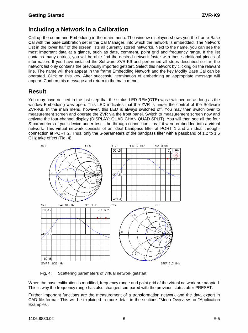
ResultYou may have noticed in the last step that the status LED REM(OTE) was switched on as long as thewindow Embedding was open. This LED indicates that the ZVR is under the control of the SoftwareZVR-K9. In the main menu, however, this LED is always switched off. You may then switch over tomeasurement screen and operate the ZVR via the front panel. Switch to measurement screen now andactivate the four-channel display (DISPLAY: QUAD CHAN QUAD SPLIT). You will then see all the fourS-parameters of your device under test - the through-connection - as if it were embedded into a virtualnetwork. This virtual network consists of an ideal bandpass filter at PORT 1 and an ideal through-connection at PORT 2. Thus, only the S-parameters of the bandpass filter with a passband of 1.2 to 1.5GHz take effect (Fig. 4).
Fig. 4: Scattering parameters of virtual network getstart
When the base calibration is modified, frequency range and point grid of the virtual network are adopted.This is why the frequency range has also changed compared with the previous status after PRESET.
Further important functions are the measurement of a transformation network and the data export inCAD file format. This will be explained in more detail in the sections "Menu Overview" or "ApplicationExamples".

ZVR-K9 Menu Overview
1106.8830.02 7 E-5
Menu Overview
In this section, all functions are listed according to their order in the main menu.
When a command is called up from the main menu, the network analyzer changes to the REMOTEstatus. Thus only in the main menu can the ZVR be operated via the front panel after switchover to themeasurement screen by means of the key combination Alt + Sys Rq.
Attention: This Windows application controls the ZVR via the DDE interface. This iswhy the network analyzer can not be controlled via IEC/IEEE-bus whileZVR-K9 is active.
File
This command opens a submenu containing the functions for the data transfer between ZVR-K9 andCAD programs as well as for the management of transformation networks. Furthermore, the systemconfiguration (hardware platform) may be defined here. The Software ZVR-K9 can also be left via File.This menu is available even when ZVR-K9 has been installed on a PC.
Import File
The function Import File permits to import files which contain the S-parameters of virtual networks in thedata format of CAD programs. This function can be used e.g. to design ideal transformation networks ina CAD program and import their S-parameters as a network. Likewise, it is possible to export ameasured network, process it in a CAD program and import the modified network back to the SoftwareZVR-K9.

Menu Overview ZVR-K9
1106.8830.02 8 E-5
Supported are the data base formats of Ansoft /Compact Software (e.g. Super Compact , Serenade )with the file name extension .flp and of Agilent EESof EDA (Touchstone , Series IV , ADS ) with theextension .s4p. An example of the flp.format is the file getstart.flp in the directory c:\rsapplic\demo.
When importing the S-parameters of a transformation network, the correct definition of the port numbersis crucial. For four-ports numbering is sequential from left to right (Fig. 5)
DUTTN1 TN21 2 3 4
PORT 1 PORT 2
Fig. 5: Numbering of the ports of the transformation network
Caution: It is very important to observe the assignment of the ports in order to avoidfaulty results.
A possible coupling of the sub-two-ports TN1 and TN2 is not taken into account, i.e. the upper right andthe lower left (2x2) sub-matrix of the four-port S-matrix is taken to be zero. To avoid singularities, thefour-port S-parameters S12 and S43 must be different from zero, i.e. the two-ports TN1 and TN2 transmitin at least one direction.
Alternatively, one may compose the transformation network of two different two-port files. In this case,port 1 of TN1 and TN2 is always oriented towards the device under test, which requires the parameterS21 to be different from zero. Furthermore, it is also possible to import a sub-two-port of a four-port.
In addition, one-port reflection factors may be imported as well. The reflection factor is interpreted as S11
and S22 of a symmetric two-port, which has an ideal transmission factor equal to 1.
Before completing the import of the transformation network one may modify its sub-two-ports. A two-portmay be turned to reverse orientation or replaced by an ideal through-connection.
The point grids of the files to be imported must be either linear or logarithmic and must coincide for thetwo sub-two-ports. The reference impedances of the sub-two-ports must be identical, too. Besides, forfiles in the Ansoft format, it is checked whether the point grid data in the file header is consistent with theactual data set in the file body.
All complex data formats supported by the aforementioned CAD programs are recognized. These aremagnitude and phase, magnitude in dB and phase as well as real and imaginary part. Permissible unitsfor frequency indications are Hz, kHz, MHz and GHz.

ZVR-K9 Menu Overview
1106.8830.02 9 E-5
Detailed procedure:
Window Import Network:
The frame Select File enables one to select path and name of the file to be imported. Only files with theextension .flp (Ansoft format) or .snp (Agilent-EESof format, n = 1, 2 or 4) are displayed. Atransformation network is always a four-port that consists of the two sub-two-ports TN1 and TN2. Thesetwo-ports can be configured independently. This is accomplished by clicking on either box TN1 or TN2,which makes the selected box turn red and opens the frame Select Action. TN1 and TN2 are pre-defined as through-connections, in this case only the keypad Insert Selected File is available. Clickingon it, the format of the file selected in the frame Select File is examined. After this check has beenpassed, the name of the selected file, instead of THROUGH, appears in the box. Otherwise, a messagebox indicates which error has been found in the format.
If a four-port is to be imported, one may click on either of TN1 or TN2. The user is prompted to decidewhether the complete four-port should be read or just the selected sub-two-port.
After having pre-selected a file, the other two keypads in the frame Select Action will become available,too. Replace by Ideal Through Connection restores the original state, i.e. an ideal through connection isassumed for the selected two-port. Interchange Ports interchanges port 1 and port 2 of the two-port,which means that S11 and S22, as well as S12 and S21, swap their places in the S-matrix. In the graph theport numbers are interchanged.
The sub-two-ports TN1 and TN2 may be modified as often as desired. When the final configuration hasbeen found, the actual file import is started via the keypad Import Network(s). The progress of the threecalculation steps that are performed is indicated by a bar in the status area.
Menu Overview ZVR-K9
1106.8830.02 10 E-5
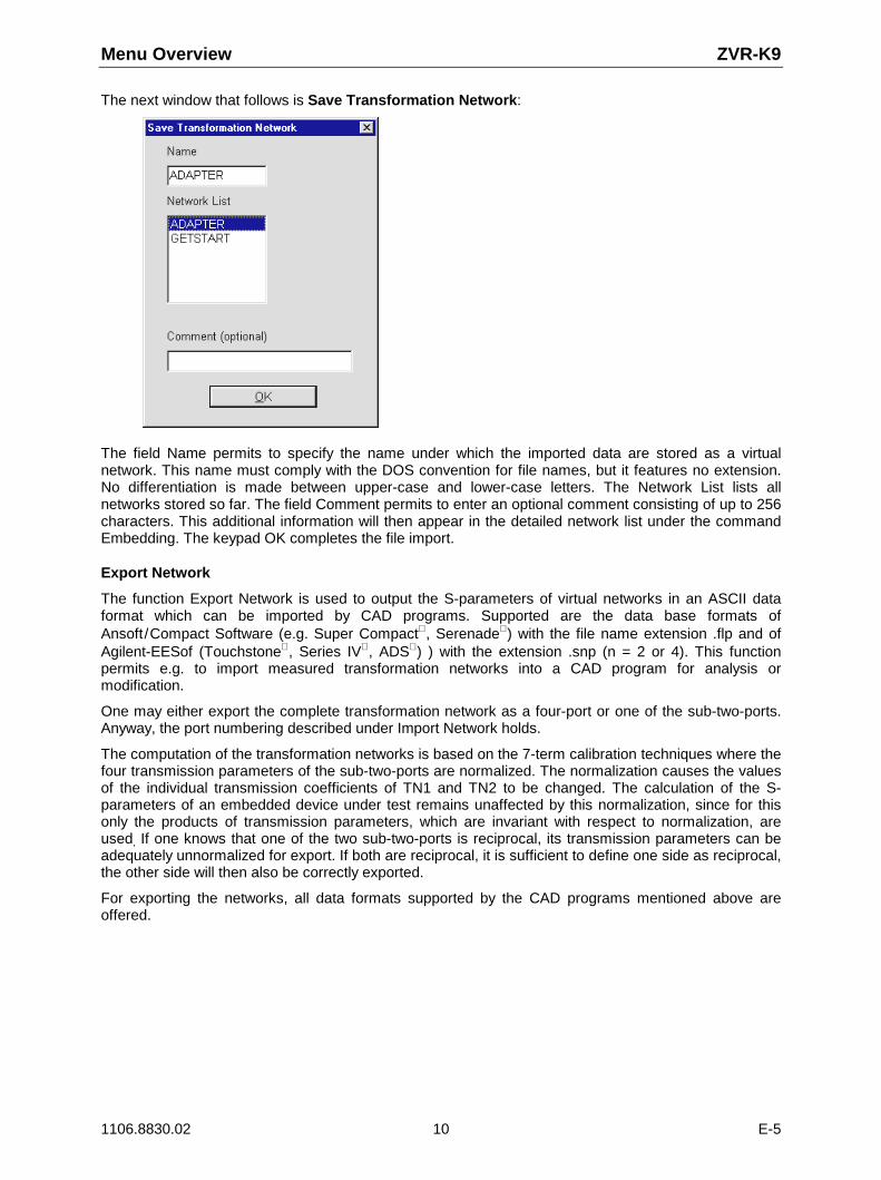
The next window that follows is Save Transformation Network:
The field Name permits to specify the name under which the imported data are stored as a virtualnetwork. This name must comply with the DOS convention for file names, but it features no extension.No differentiation is made between upper-case and lower-case letters. The Network List lists allnetworks stored so far. The field Comment permits to enter an optional comment consisting of up to 256characters. This additional information will then appear in the detailed network list under the commandEmbedding. The keypad OK completes the file import.
Export Network
The function Export Network is used to output the S-parameters of virtual networks in an ASCII dataformat which can be imported by CAD programs. Supported are the data base formats ofAnsoft /Compact Software (e.g. Super Compact , Serenade ) with the file name extension .flp and ofAgilent-EESof (Touchstone , Series IV , ADS ) ) with the extension .snp (n = 2 or 4). This functionpermits e.g. to import measured transformation networks into a CAD program for analysis ormodification.
One may either export the complete transformation network as a four-port or one of the sub-two-ports.Anyway, the port numbering described under Import Network holds.
The computation of the transformation networks is based on the 7-term calibration techniques where thefour transmission parameters of the sub-two-ports are normalized. The normalization causes the valuesof the individual transmission coefficients of TN1 and TN2 to be changed. The calculation of the S-parameters of an embedded device under test remains unaffected by this normalization, since for thisonly the products of transmission parameters, which are invariant with respect to normalization, areused, If one knows that one of the two sub-two-ports is reciprocal, its transmission parameters can beadequately unnormalized for export. If both are reciprocal, it is sufficient to define one side as reciprocal,the other side will then also be correctly exported.
For exporting the networks, all data formats supported by the CAD programs mentioned above areoffered.

ZVR-K9 Menu Overview
1106.8830.02 11 E-5
Detailed procedure:
Window Export Network:
The Network List lists all networks stored. Set the selection bar to the network to be exported and selectthe keypad Export Network.
Window Select Export File Options:
This window is used to determine the options for data export. Within the frame Export Subnetwork, onecan decide whether the complete transformation network is to be exported or just a sub-two-port. Theframe Reciprocal Subnetwork allows the user to determine whether and how the unnormalization of thetransmission parameters shall be performed. The frame File Format permits one to choose either theAnsoft (formerly: Compact Software) or the Agilent-EESof format. The output format for the complex S-parameters is selected in the frame Complex Data Format. It is possible to choose between magnitudeand phase, logarithmic magnitude (in units of dB) and phase as well as real and imaginary part. Finally,the frequency unit can be selected in the frame Frequency Unit. Here, the possible units are GHz, MHz,kHz and Hz. Having defined all options select the keypad Save Export File.
The frequency values and S-parameters are stored with an accuracy of 7 digits after the decimal point.

Menu Overview ZVR-K9
1106.8830.02 12 E-5
Window Save Export File:
This window is used to determine the path and the name of the file to be exported. According to the dataformat selected before, a file name extension is determined automatically. Save starts the storageprocedure. Its successful termination is indicated by a message that is to be confirmed by the user.
Network Manager
The window Network Manager is used for the management of transformation networks.
Transformation networks can be renamed, deleted or loaded from the ZVR into the controllingcomputer. The Network List on the left lists all stored networks. The desired network can be selectedusing the selection bar. To rename a network press the keypad Rename, which will open a field forentering the new name. Network names must comply with the DOS convention for file names, but donot contain any extension. The keypad Delete deletes the selected network. For the LAN Configuration(see Window Hardware Configuration), the keypad Load Networks from NWA is available, too. It opensa window having the same name.

ZVR-K9 Menu Overview
1106.8830.02 13 E-5
This window is useful for copying transformation networks from the ZVR to the controlling computer.The NWA Network List shows the networks that are stored in the ZVR, choose those which are to becopied by means of a selection bar. Select All selects the whole list. Load Selected Networks loads allselected networks into the controlling computer. The window is closed via Close.
Hardware Configuration:
The window Hardware Configuration allows the user to specify the hardware platform for the softwareZVR-K9:
If the software ZVR-K9 runs on a ZVR under Windows NT, choose Stand-alone Network Analyzer.
ZVR-K9 can also be run on a Windows PC, in this case the option Stand-alone MS Windows Computermust be selected. For this configuration, however, the main menu contains only the File and Infosubmenus, thus only transformation network management functions are available.If the ZVR is connected to a computer network via an Ethernet adapter (option FSE-B16), the ZVR-K9software may also be started from any Windows computer in the network. In this case, choose the LANConfiguration option, then all functions of ZVR stand-alone operation are available. Enter the IP addressof the ZVR into the IP Address field using the format 12.34.56.78. Note that calibration data (Cal List)are always related to the network analyzer and thus kept in it, whereas transformation networks(Network List) are stored in the controlling computer. If there are transformation networks on the ZVR,they may be copied to the controlling computer by means of the function Load Networks from NWA (seeNetwork Manager). A special case of the LAN Configuration should be mentioned, which is stand-alone

Menu Overview ZVR-K9
1106.8830.02 14 E-5
operation of a ZVR. In this case, ZVR-K9 running on the network analyzer controls the analyzer via istown IP address.
As long as the Hardware Configuration window is open, configuration changes do not yet becomeeffective. It is the Change Configuration keypad that accepts the selected configuration and quits thewindow. If no change is desired, one may return to the main menu via the keypad Exit without change.
Exit
The command Exit terminates the Software ZVR-K9.
Measure Network
This command can be used to measure transformation networks (Unterminating problem). This isparticularly useful if the network to be virtually considered later is physically present (e.g. test fixture,component case) but be designed via CAD with sufficient accuracy. The scattering parameters of thenetwork can be determined by carrying out a calibration at the outer and inner ports and by forming thedifference between the respective error four-ports. This procedure can be used if both the outer and theinner ports are directly accessible.
In some cases, however, the desired transformation network is inseparably connected with an auxiliarynetwork. If the auxiliary network alone (e.g. a test fixture without transformation elements) is alsophysically existing, a two-stage procedure permits to determine first the auxiliary network and theauxiliary network plus transformation network and finally the transformation network itself by means ofthree calibrations. This case is referred to as “indirect access“. As a prerequisite, the outer ports ofauxiliary network and auxiliary network plus transformation network must feature the same connectortype so that one common outer calibration is sufficient.
Inner and outer calibrations, on the other hand, do not necessarily refer to the same connector type. Forexample, test fixtures for non-coaxial components (SMD cases etc.) with coaxial outer connectors canalso be measured. For non-coaxial inner calibrations, 7-term self-calibration techniques arerecommended, such as e.g. TRL, TRM or TNA, which do not require all standards to be completelyknown.
The two partial two-ports TN1 and TN2 as well as, if applicable, the auxiliary networks AN1 (= AuxiliaryNetwork 1) and AN2 must be transmitting. To avoid numerical inaccuracies, the transmission lossshould not exceed 50 dB.
Detailed procedure:
Before calling up Measure Network, frequency range, point grid and other desired sweep settings for thecalibration measurements must be set via the front panel of the ZVR. The main menu permits to switchbetween measurement and PC screen using the key combination Alt + Sys Rq.

ZVR-K9 Menu Overview
1106.8830.02 15 E-5
Window Access to Transformation Network(called up by the command Measure Network in the main menu):
This window permits to determine whether the transformation network to be measured is directlyaccessible (keypad Direct) or connected to an auxiliary network (keypad Indirect). Both cases areillustrated by graphs showing the reference planes for inner and outer calibration.
In the case of indirect access, the assumption is made that the transformation network is connected tothe outer ports of the combination transformation/auxiliary network. Thus it can be taken into account inthe system correction data of the NWA later. As all this represents only a model, it is irrelevant whetherthe real transformation and auxiliary networks are actually connected in series as described above.
Window Direct Measurement(called up via keypad Direct in the window Access to Transformation Network):
This window permits to start inner (keypad Inner Cal) and outer calibration (keypad Outer Cal) as well asthe final computation of the transformation network. The order of inner and outer calibration is arbitrary.The keypad Calculate Transformation Network, however, can only be operated after both calibrationshave been performed. The BACK button leads back to the previous window. This button is alsoavailable in most of the windows described in the remainder of this section. Within the Measure Networkmenu, the order in which the windows are called up is stored, so it is possible to return to the previouswindows by pressing the BACK button repeatedly.

Menu Overview ZVR-K9
1106.8830.02 16 E-5
Window Direct Inner Calibration: Cal Source(called up via keypad Inner Cal in the window Direct Measurement):
This window permits the user to choose between using the currently active calibration of the ZVR asinner calibration (keypad Use Active Calibration) and performing a new calibration (keypad Start NewCalibration). If you select the currently active calibration, this is restored with the original sweep settingsvalid when this calibration was performed. The same is true if the calibration was switched off. Thus,point grid, generator level, internal/external operating mode, etc. may change. If an outer calibrationalready exists, it becomes invalid. These sometimes undesired results of the function Use ActiveCalibration are indicated in a message window which is to be confirmed by the user and from where thefunction can be aborted.
Window Inner Calibration: Define Connector and Cal Method(called up via keypad Start New Calibration in the window Inner Calibration):
This window permits to determine connector type and sex of the test ports as well as the calibrationmethod for the inner calibration. When the ZVR is operated via the front panel, these parameters arepolled in successive menus. One of the four 7-term techniques (Txx) implemented in the ZVR can beselected as a calibration method. The keypad Measure Calibration Standards can only be operatedwhen the necessary entries have been made.

ZVR-K9 Menu Overview
1106.8830.02 17 E-5
Window Direct Inner Calibration: Txx(called up via keypad Measure Calibration Standards in the window Inner Calibration: Define Connectorand Cal Method):
These windows correspond to the calibration measurement menus for 7-term techniques with ZVRoperation via the front panel. The softkeys for measuring the standards are simulated by keypads interms of labeling and functions. By actuating a keypad, the calibration sweep is triggered; when it isfinished, the key turns green. All standards can be measured in any order and as often as desired.While the individual standards are measured, a plausibility check is performed. A message window popsup if any of the measurement results appear implausible. The keypad Apply Calibration can only beoperated when the minimum number of standards have been measured. Apply Calibration permits toreturn to the window Direct Measurement after computation of the correction values. A message windowappears also if the implicit verification procedure during the calculation of the correction coefficientsyields and error or if any of the standards are not defined in the current sweep range. The keypad InnerCal turns green to indicate that the inner calibration has been performed. If required, it can be repeatedas often as desired like the measurement of a single standard.
Window Direct Outer Calibration: Cal Source(called up via keypad Outer Cal in the window Direct Measurement):
For the outer calibration the same is true as for the inner one. After the inner and outer calibration havebeen performed, the key Calculate Transformation Network in the window Direct Measurement can beoperated.
Window Save Transformation Network(called up via keypad Calculate Transformation Network in the window Direct Measurement):
This window is identical to the one described under File – Import. The field Name permits to determinethe name under which the imported data are stored as virtual network. This name must comply with theDOS convention for file names and has no extension. No differentiation is made between upper-caseand lower-case letters. The Network List lists all networks stored so far. The field Comment permits toenter an optional comment with a length of up to 256 characters. This additional information will thenappear in the detailed network list under the command Embedding.
After confirmation with OK, the difference between inner and outer calibration is formed and stored astransformation network. A bar in the status line shows the progress of the storage procedure. After thestorage, the window Measure Network appears which permits to return to the window DirectMeasurement (page 17) via the keypad Meas Window. This may be useful if, after storage, you noticethat an error has occurred in a calibration and you want to repeat this calibration. The other keypad MainMenu permits to return to the main menu, deleting the inner and outer calibration. In this case, thewindow Active Calibration enables you to adopt the outer calibration as the active one. Actually, theouter calibration is often identical with the one in which the network is to be considered in the followingstep.

Menu Overview ZVR-K9
1106.8830.02 18 E-5
Window Indirect Measurement(called up via keypad Indirect in the window Access to Transformation Network):
In the case of the indirect measurement of a transformation network, two physical networks are given,namely the auxiliary network combined with the transformation network as well as the auxiliary networkalone. For example, the combination of auxiliary network and transformation network may be a testfixture with integrated matching circuit, the auxiliary network alone a test fixture without matching circuit.Therefore, as opposed to the direct measurement, two inner calibrations are required. The keypad InnerCal AN+TN starts the calibration with auxiliary and transformation network, the keypad Inner Cal ANonly starts the calibration with the auxiliary network only. In terms of key functions and test procedure,the indirect measurement corresponds to the direct measurement.
Both for inner and outer calibrations, it is possible to select the currently active one. All other calibrationsare thus reset to the “not performed“ status, the corresponding keys turn gray.

ZVR-K9 Menu Overview
1106.8830.02 19 E-5
Embedding
The command Embedding opens the Embedding window which permits to consider a virtualtransformation network in the system error correction data:
A device under test, which is measured with correction data modified like this, behaves as if it wereembedded into the transformation network. The original calibration before the modification is referred toas base calibration. This may be either the currently active calibration or a calibration from the Cal List ofthe Cal Manager. Configuration of the base calibration is also performed in the Cal Manager. Thecurrent base calibration is indicated in the frame Base Cal.
The embedding virtual transformation network is selected from the Network List. In addition to the nameof the network, this list includes a number of other important data, such as date of storage, comment,point grid and frequency range. These data make it easier to find a desired network. If required, thecolumn lines of the Network List can be shifted using the cursor, e.g. in order to make a longer commentcompletely visible. If not all networks can be shown in the list, a scrollbar will appear at the right-handedge. A network can be selected by clicking on it with the mouse, the respective line being displayed oncolored background. The name of the currently selected virtual network is indicated in the frameEmbedding Network.
Modify Base Cal
The keypad Modify Base Cal starts the computation of the modified calibration. A bar in the status lineindicates the progress of the computation. After successful termination, a message is output, themodified calibration is activated and the program returns to the main menu level.
The base calibration must have been performed according to a Txx technique (7 error terms).Therefore, normalization, one-port calibration or 12-term calibration (TOSM) cannot be used.
The modified calibration features the same point grid as the virtual network. In the computation, aninterpolation is made between the sampling points of the base calibration. However, this assumes thatthe base calibration completely covers the frequency range of the virtual network, i.e. extrapolationbeyond the frequency range of the base calibration is not possible.
To ensure correct calculation of the modified correction data, the S-parameters of virtual network andbase calibration must be referred to the same impedance. Otherwise, a warning will appear.

Menu Overview ZVR-K9
1106.8830.02 20 E-5
The modified correction data are only used in the active display channel unless the channels arecoupled. It is of no importance whether the base calibration was recorded with coupled or decoupledchannels.
Close
The keypad Close closes the window Embedding and allows to return to the main menu.
De-Embedding
The result of the command De-Embedding is inverse to that of the command Embedding. WhereasEmbedding permits to embed a DUT into a virtual transformation network, De-Embedding can be usedto virtually remove a physically existing network. This is achieved by considering the inverse virtualnetwork in the system error correction data. Of course, the scattering parameters of the network mustbe known for this purpose.
For operation and procedure refer to the command Embedding.
Cal Manager
The window Cal Manager provides functions for the management of system error correction data:
System error correction data can be stored on the hard disk irrespective of the SAVE-RECALLmechanism of the ZVR. The active correction data can be stored under a freely selectable name,conversely, the stored data can be activated again. The files stored are displayed in the Cal List.Correction files can be renamed or deleted. The Cal Manager also permits to determine the basecalibration to be used for embedding or de-embedding. Possible base calibrations are the activecalibration or the one marked in the Cal List.

ZVR-K9 Menu Overview
1106.8830.02 21 E-5
Append Active Cal to List
The function Append Active Cal to List adds the active calibration to the Cal List. The correction data aretransferred, irrespective of whether they are permissible as base calibration for embedding or de-embedding. The name may comprise up to 8 characters. The keypad Append Active Cal to List can onlybe operated if an active calibration is available.
Set Cal Active
The function Set Cal Active permits to activate the calibration marked in the Cal List by means of theselection bar. This keypad can only be operated if there are entries in the Cal List.
Rename Cal
The function Rename Cal is used to rename the calibration marked in the Cal List by means of theselection bar. The name may comprise up to 8 characters. This keypad can only be operated if thereare entries in the Cal List.
Delete Cal
The function Delete Cal permits to delete the correction file marked in the Cal List by means of theselection bar. This keypad can only be operated if there are entries in the Cal List .
Close
The keypad Close closes the Cal Manager and returns to the main menu.
Set Base Cal
The function Set Base Cal is used to determine the base calibration, which is modified by thecommands Embedding and De-Embedding in the main menu. It is possible to choose between activecalibration (button Active Cal) and the calibration marked in the Cal List (button Selected Cal from List).This selection is to be made before actuating the keypad Set Base Cal.
The currently selected base calibration is indicated both at the top left in the frame Set Base Cal for(De-)Embedding and in the frame Base Cal at the top left in the window Embedding or De-Embedding.
Info
The command Info calls up the program information for Software Option ZVR-K9.
The OK button closes this window.
Application Examples ZVR-K9
1106.8830.02 22 E-5
Application Examples
Embedding: Testing SMD Components with a Virtual Matching Network
In the application circuit certain components are embedded into a matching network. For example, high-impedance SAW filters to be integrated into a 50-ohm system must be provided with a transformationcircuit. The behavior in the circuit is determined by the composite network consisting of component andtransformer only. Therefore, these components are often specified together with the matching networkand must therefore also be tested in the matching circuit.
The component test with matching network involves the problem that measurement results of varioustest fixtures of the same type are comparable only to a limited extent because of the unavoidabletolerances of the matching network. This implies that a relatively high measurement uncertainty has tobe assumed, which is to be subtracted from the specified values in the component test and thus resultsin a poorer yield. Therefore, it would be favorable to use a virtual, tolerance-free matching circuit in themeasurement instead of a real one.
This virtual matching circuit can either be calculated with the aid of a CAD program, or a physicallyexisting circuit is measured. The second procedure is to be recommended if there are parasitic effectswhich are difficult or impossible to account for in a model.
For testing SMD components, a test fixture is required. Necessary matching networks are oftenintegrated into this test fixture. If one wants to change over to virtual matching networks, a test fixture isstill to be used for electrical matching of the DUT, however, it is usually less complex and does notcontain a physical matching network. In most cases, the matching network itself cannot be measured onits own.
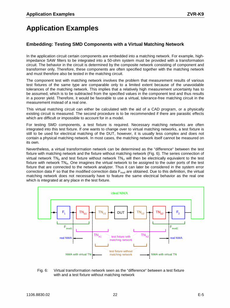
Nevertheless, a virtual transformation network can be determined as the “difference“ between the testfixture with matching network and the fixture without matching network (Fig. 6). The series connection ofvirtual network TN∆ and test fixture without network TNU will then be electrically equivalent to the testfixture with network TNA. One imagines the virtual network to be assigned to the outer ports of the testfixture that are connected to the network analyzer. Thus it can later be considered in the system errorcorrection data F so that the modified correction data Fmod are obtained. Due to this definition, the virtualmatching network does not necessarily have to feature the same electrical behavior as the real onewhich is integrated at any place in the test fixture.
F
3 1
real NWA
F ∆1TN DUT
ideal NWA
NWA with virtual TN
test fixture withmatching network
U1TN U2TN ∆2TN
real NWAA1TN A2TN
mod1
test fixture withoutmatching network
Fmod2
1 F2
NWA with virtual TN
Fig. 6: Virtual transformation network seen as the “difference“ between a test fixturewith and a test fixture without matching network

ZVR-K9 Application Examples
1106.8830.02 23 E-5
A typical test fixture has coaxial connectors where the test cables of the network analyzer areconnected, and contacts for the DUT which are matched to the shape of the case of the component tobe measured. For determination of the virtual network the assumption is made that the coaxialconnectors at the test fixtures with and without matching network are identical. The virtual network canthen be calculated by means of three calibrations.
The command Measure Network leads to the window Access to Transformation Network, which permitsto call up the window Indirect Measurement via the keypad Indirect. The reference plane of the outercalibration started with Outer Cal are the generally coaxial ports of the test fixture to which the networkanalyzer is connected.
For the two inner calibrations that are performed at the contacts to the DUT, special calibrationstandards are required. By installing these standards into a case corresponding to the DUT, you canmake sure that the field distribution at the test ports is the same for calibration and measurement. Ofcourse, this is only possible if the case can approximately be regarded as matched and loss-free. In thecase of non-coaxial test ports, the production of precise standards is particularly difficult. It is thereforerecommended to use a self-calibration method such as TRM, TRL or TNA for the inner calibrations,where not all standards have to be known exactly. For TRM, e.g., it is sufficient to use a piece of atransmission line with reference impedance Z0 and known length, besides two terminations with Z0. TheREFLECT standard can be implemented by leaving the contacts open in the case of symmetrical testfixture contacts.
After the calibrations have been performed, the virtual matching network is calculated and stored via thekeypad Calculate Transformation Network. It can then be embedded in the previously recordedcalibration or in a new outer coaxial calibration. If you measure a component in the test fixture withoutmatching network by means of this modified calibration, the same result will be obtained as if you hadused the original calibration and the test fixture with matching network.
De-Embedding: Measurement of “Embedded“ Components
A further case of application for the Software Option ZVR-K9 is the characterization of embeddedcomponents. These are not accessible for a direct measurement, because they are inseparablyconnected with a transformation network. For example, one might want to measure the scatteringparameters of an MMIC, which cannot be removed from its case. Another example is the investigationof the transmission, reflection and crosstalk of a connector for printed circuit boards. To be able toconnect this connector to a network analyzer, male and female connector are each soldered into anadapter board with coaxial connections. If the characteristics of the connector alone are to bedetermined, the adapter boards must be removed computationally.
If the scattering parameters of the transformation network are known, measurement problems like thiscan be solved with the aid of the de-embedding procedure. If it is not possible to simulate the networkwith sufficient accuracy using a CAD program, the scattering parameters must be measured. Unlike inthe above application example, the command Measure Network now permits to select direct access tothe network ports. In this case, one calibration must be performed at the inner ports and one at the outerports of the transformation network. For non-coaxial devices under test, the calibration procedures TRMor TNA are suitable. If the transformation network is an SMD case, special standards are required bothfor the inner and outer calibration. If reproducible case characteristics can be assumed, it is often usefulfor the inner calibration to install the standards permanently in the case.

Application Examples ZVR-K9
1106.8830.02 24 E-5
Measuring a Microstrip Transition
In the de-embedding example mentioned above, one part of the measuring task was to determine theembedding transformation network. However, it may even be the measuring task itself to determine anddisplay the S-parameters of a transformation network.
In state-of-the-art microwave circuits, there is a growing tendency towards the exclusive use of planartransmission line structures without coaxial interfaces. It is conceivable, e.g., that several microwavemodules on ceramic substrates are combined on a printed epoxy motherboard (PCB) which containsonly RF connections and AF circuits to form a single module. The transition from the printed circuitboard to the ceramic substrate must be as low-reflection and low-loss as possible.
If the transition is regarded as a transformation network, it can be determined by forming the differencebetween calibrations at the outer ports (on the PCB) and the inner ports (on the ceramic substrate). TheTRM or TNA method should be used for the calibrations. Fig. 7 shows the calibration standards used.
THROUGH
NETWORK
ATTENUATION
2x OPEN
printed circuit board(TRM-calibration)
calibration substrates(TNA-calibration)
2x SHORT
2x MATCH
contact surfaces
contact springs
Fig. 7: Calibration standards for measuring a transitionfrom printed circuit board to ceramic substrate
The command Measure Network permits to determine the S-parameters of the transition and store themas a transformation network. To make them visible, the network can be exported in a CAD file format(e.g. Serenade, Series IV, ADS) and imported by the respective program as a black-box element. Fig. 8shows the S-parameters of such a transition. Of course, the CAD program also permits to investigate itsbehavior in a simulated circuit environment or match a transition model to the measured data byoptimizing the parameters. If required, the modified model can then be imported again as a virtualnetwork into the Software ZVR-K9.

ZVR-K9 Application Examples
1106.8830.02 25 E-5
Fig. 8: S-parameters of a transition from PCB to ceramic substrate


ZVR-K9 Index
1106.8830.02 I.1 E-5
Index
AAccess
Direct.........................................................................15Indirect ......................................................................14
Access to Transformation Network (Window) ..................15Active calibration (window) ..............................................17ADS...................................................................................8Agilent EESof EDA (CAD programs) .................................8Ansoft /Compact Software (CAD programs).......................8Application examples
De-Embedding...........................................................23Embedding ................................................................22Measure microstrip transition.....................................24
Application Examples ......................................................22Auxiliary network .......................................................14, 18
BBase calibration ...............................................................19
Set.............................................................................21
CCAD file
Import ..........................................................................5CAD program.....................................................................2Cal List ............................................................................20Cal Manager
Command..................................................................20Window .....................................................................20
Calibration .........................................................................5Activate .....................................................................21Base..........................................................................19Close.........................................................................21Inner..........................................................................16Manage data .............................................................20Modified.....................................................................19Outer .........................................................................17Store ...........................................................................5TXX ...........................................................................17
Calibration measurement menu .......................................17Calibration method
Inner calibration.........................................................16Circuit environment
Simulated ....................................................................2Command menus ..............................................................7Connecor Type ................................................................16
DDatabase formats
Input ............................................................................8De-embedding ...................................................................2De-Embedding.................................................................20Device under test
Embed.......................................................................19Remove network .......................................................20
Direct Inner CalibrationCal Source (Window).................................................16TXX (Window) ...........................................................17
Direct measurement (Window).........................................15Direct Outer Calibration
Cal Source (Window).................................................17
EEmbedding
Network ...................................................................... 6Embedding (Command) .................................................. 19Embedding, Virtual ............................................................ 1Exit (Command) .............................................................. 14Export network
Command ................................................................. 10Window..................................................................... 11
FFile
Import ......................................................................... 9Output....................................................................... 12
File (Command menu)....................................................... 7Firmware version............................................................... 3Formats (files) ................................................................... 8Functions .......................................................................... 2
GGetting Started.................................................................. 5
HHardware Configuration (Window)................................... 13
IImport
CAD file ...................................................................... 5Import File
Command ................................................................... 7Import Network
Window....................................................................... 9Indirect measurement (window)....................................... 18Info (Command) .............................................................. 21Inner calibration (Window)
Define connector and cal method.............................. 16Installation......................................................................... 4Introduction ....................................................................... 1
Kkey code number............................................................... 4
LLED REM(OTE) ................................................................ 6
MMeasure Network ............................................................ 14Measure network (window) ............................................. 17Measuring task
De-embedding ............................................................ 2Embedding.................................................................. 1Unterminating.............................................................. 2
Measuring Tasks............................................................... 1
NNetwork

Index ZVR-K9
1106.8830.02 I.2 E-5
Embedding ..................................................................6Network export
options.......................................................................11Network Manager (Window) ............................................12
PPoint grid ...........................................................................8Port..................................................................................16Preparation........................................................................5Program Information ........................................................21
RReference Part ..................................................................7REMOTE status.................................................................7
SSave Export File (Window) ..............................................12Save transformation network
Window .....................................................................10Save transformation network (window) ............................17Select Export File Options
Window .....................................................................11Serenade...........................................................................8Series IV............................................................................8Setup program...................................................................4Simulated circuit environment ............................................2SMD Components ...........................................................22S-parameters
Import ..........................................................................7Output .......................................................................10
Start calibration................................................................15
Status display.................................................................... 6Super Compact ................................................................. 8System error correction data
Manage..................................................................... 20Modify ....................................................................... 20
System Requirements ....................................................... 3
TTest port.......................................................................... 16Touchstone ....................................................................... 8Transformation network
Access ...................................................................... 15Direct measurement.................................................. 15Embedding................................................................ 19Indirect measurement ............................................... 18Inverse........................................................................ 2Measure.................................................................... 14Store ......................................................................... 17Virtual ......................................................................... 1
Transformation network..................................................... 1Transformation Network
Management ............................................................. 12
VVersion number (Firmware)............................................... 3
ZZVR-K9
Functions .................................................................... 2LED display................................................................. 6