Embed Size (px)
Citation preview
ENERGO-PRO a.s.
Zoti Hydropower Project, Georgia
Basic design
Report No. 1646-03
FINAL VERSION
August 2009
AF-Colenco Ltd Hydropower Department

ENERGO-PRO, Zoti HPP Georgia Basic Design Report 2/65
Table of Contents
Page
1 Introduction .......................................................................................................................8
2 Location and General Layout of the Project .....................................................................8
3 Geology and Seismic Activity...........................................................................................9
4 Topography .....................................................................................................................11
5 Hydrology Data ...............................................................................................................11
5.1 Inflow ..............................................................................................................................14
5.2 Ecological water release..................................................................................................15
5.3 Design floods...................................................................................................................15
5.4 Sediment yield and sediment transport ...........................................................................16
6 Design Parameters...........................................................................................................16
6.1 General considerations ....................................................................................................16 6.1.1 Selling prices for energy in Georgia................................................................................16 6.1.2 Water Usage Permission .................................................................................................17 6.1.3 Land Acquisition .............................................................................................................17
6.2 Economical Parameters ...................................................................................................17 6.2.1 Unit Prices and Currency ................................................................................................17 6.2.2 Site Installation................................................................................................................17 6.2.3 Contingencies, Environmental & Social Costs ...............................................................18 6.2.4 Construction Period.........................................................................................................18 6.2.5 Maintenance & Operation Cost.......................................................................................18 6.2.6 Concession Duration and Discount Rates .......................................................................18
7 Power potential study ......................................................................................................18
8 Project Layout .................................................................................................................22
8.1 Salient Features ...............................................................................................................22 8.1.1 Schematic Longitudinal Profile.......................................................................................26 8.1.2 Reservoir Management....................................................................................................26 8.1.3 Installed Capacity and Energy Production ......................................................................28
8.2 Civil Engineering Structures ...........................................................................................28 8.2.1 Diversion Khinistskali .....................................................................................................28 8.2.1.1 Intake and Desilting Facilities.........................................................................................28 8.2.1.2 Diversion Tunnel Khinistskali.........................................................................................29 8.2.2 Gubazeuli Dam and Intake ..............................................................................................29 8.2.2.1 Dam Type ........................................................................................................................29
ENERGO-PRO, Zoti HPP Georgia Basic Design Report 3/65
8.2.2.2 Intake structure ................................................................................................................31 8.2.3 Diversion Gubazeuli Creek .............................................................................................32 8.2.3.1 Intake and Desilting Facilities.........................................................................................32 8.2.3.2 Diversion Tunnel GubazeuliCreek..................................................................................33 8.2.4 Diversion Kvirilas ...........................................................................................................33 8.2.4.1 Intake and Desilting Facilities.........................................................................................33 8.2.4.2 Diversion Tunnel Kvirilas ...............................................................................................34 8.2.5 Headrace tunnel ...............................................................................................................34 8.2.6 Upstream Surge Shaft......................................................................................................35 8.2.6.1 Transient Analysis...........................................................................................................35 8.2.7 Pressure Shaft and Valve Chamber .................................................................................38 8.2.8 Underground Powerhouse and Transformer cavern........................................................39 8.2.8.1 Multipurpose access tunnel .............................................................................................39 8.2.8.2 Tailrace tunnel .................................................................................................................40 8.2.9 Mechanical Equipment....................................................................................................40 8.2.9.1 Number of units and units arrangement ..........................................................................40 8.2.9.2 Rotating speed .................................................................................................................41 8.2.9.3 Modes of operation..........................................................................................................41 8.2.9.4 Turbine and governor ......................................................................................................41 8.2.9.5 Main Inlet Valve..............................................................................................................42 8.2.9.6 Cooling Water System.....................................................................................................42 8.2.9.7 Drainage and Dewatering System ...................................................................................43 8.2.9.8 Powerhouse crane............................................................................................................43 8.2.10 Electrical Equipment - Generators, Transformers, and Switchgear ................................44 8.2.10.1 Generators .......................................................................................................................44 8.2.10.2 Excitation System............................................................................................................44 8.2.10.3 Generator Step-Up Transformer......................................................................................45 8.2.10.4 Electrical Protections.......................................................................................................45 8.2.10.5 Medium Voltage Switchgear...........................................................................................46 8.2.10.6 High Voltage Switchyard (110kV)..................................................................................46 8.2.10.7 Low Voltage AC Supplier...............................................................................................47 8.2.10.8 Low Voltage DC Supplier System ..................................................................................47 8.2.10.9 Control System................................................................................................................47 8.2.10.10 Instrumentation and metering..........................................................................................48 8.2.10.11 Fire Fighting System .......................................................................................................48 8.2.10.12 Communication System ..................................................................................................48 8.2.11 Power Evacuation – Connection to Electrical Grid.........................................................48
9 Implementation Schedule ................................................................................................48
9.1 Working capacities ..........................................................................................................48
9.2 Construction Program......................................................................................................49
9.3 Construction Material Management ................................................................................52 9.3.1 Construction materials for concrete aggregates ..............................................................52 9.3.2 Cement and auxiliary materials.......................................................................................52
10 Cost Estimate...................................................................................................................53

ENERGO-PRO, Zoti HPP Georgia Basic Design Report 4/65
10.1 Unit Prices .......................................................................................................................53
10.2 Expected Investment Costs .............................................................................................54
10.3 Annual Costs and Prime Rate Cost of Energy ................................................................55
11 Environmental aspects.....................................................................................................56
12 Conclusions and recommendations .................................................................................56
13 Kvirila HPP – Quick assessment of economical feasibility ............................................57
13.1 General layout .................................................................................................................57
13.2 Salient features ................................................................................................................59
13.3 Expected Investment Costs .............................................................................................63
13.4 Annual Costs and Prime Rate Cost of Energy ................................................................64
13.5 Conclusions .....................................................................................................................65 Index of Figures
Page
Figure 1. Southeastern Georgia with the area of Zoti HPP highlighted...............................................9
Figure 2. Monthly average discharge for Khidistavi station..............................................................12
Figure 3. Flow duration curve for Khidistavi station .........................................................................12
Figure 4. Annual average rainfall in Georgia (source: http://geb.uni-
giessen.de/geb/volltexte/2005/2541/).................................................................................................13
Figure 5. Catchment areas for Zoti HPP ............................................................................................14
Figure 6. Average duration curves for all catchments .......................................................................15
Figure 7. Assumed peak values for Zoti HPP ....................................................................................16
Figure 8. Zoti HPP- Flow duration curve with the exceedance – discharge values for the power
potential study ....................................................................................................................................19
Figure 9. Optimum installed capacity based on a unique tariff .........................................................22
Figure 10. Zoti HPP- Schematic longitunal profile............................................................................26
Figure 11. Gubazeuli reservoir – volume curve.................................................................................27
Figure 12. Tyrolean intake .................................................................................................................28
Figure 13. Capacity curve of bottom outlet........................................................................................31

ENERGO-PRO, Zoti HPP Georgia Basic Design Report 5/65
Figure 14. Schema of the numerical model for transient analysis of Zoti HPP.................................36
Figure 15. Max upsurge (red line) for case-2 and max downsurge (blue line) for case-4 ................37
Figure 16. Max pressure in the steel lining (at bifurcation level) for case-2 .....................................38
Figure 17. Plan view of Kvirila HPP..................................................................................................58
Figure 18. Duration curve for Kvirila HPP........................................................................................59
Figure 19. Longitudinal profile Kvirila HPP .....................................................................................59
Index of Tables
Page Table 1: Summary of flow data recorded on the rivers Gubazeuli at Khidistavi station ...................12
Table 2: Precipitation data from Zoti meteorological station at Gubazeuli River .............................13
Table 3: Summary of the main parameters for all catchments...........................................................14
Table 4: Power potential study results ...............................................................................................21
Table 5: Main features of the reservoir Gubazeuli.............................................................................27
Table 6: Main features of the diversion Khinistskali .........................................................................29
Table 7: Main features of the Dam Zoti .............................................................................................30
Table 8: Estimated main volumes for Gubazeuli dam .......................................................................30
Table 9: Main features of the diversion Gubazeuli Creek .................................................................32
Table 10: Main features of the diversion Kvirila ...............................................................................33
Table 11: Headrace tunnel profile types ............................................................................................34
Table 12: Main features of the upstream surge shaft.........................................................................35
Table 13: Studied operating conditions..............................................................................................36
Table 14: Results of transient calculations for the studied cases .......................................................37
Table 15: Main features of the pressure shaft ....................................................................................38
Table 16: Main features of the Underground Powerhouse and transformer cavern ..........................39
Table 17: Work capacities for the main construction items...............................................................49
Table 18: Construction schedule ........................................................................................................50
Table 19. Assumed unitary rates ........................................................................................................53

ENERGO-PRO, Zoti HPP Georgia Basic Design Report 6/65
Table 20. Summary of the expected costs for Zoti HPP ....................................................................54
Table 21. Main hydrological information for Kvirilas River.............................................................58
Table 22. Salient features of Kvirila HPP..........................................................................................60
Table 23. Summary of the expected costs for Kvrila HPP.................................................................63
ANNEXES
Drawing List Basic Design
01 General Layout
Plan View
02 General Layout Schematic longitudinal Profile
03 Derivation “Khinistskali” Intake, Desander Facility and Transition Tunnel to the Gubazeuli Reservoir Plan View and Sections
04 “Gubazeuli” Reservoir Dam and Intake Structure Plan View and Sections
05 Derivation “Gubazeuli Creek” Intake, Desander Facility and Derivation Tunnel to the headrace tunnel Plan View and Sections
06 Derivation “Kvirila” – Sheet 1 Intake, desander facility and Derivation tunnel to the headrace tunnel Plan View and Sections
07 Derivation “Kvirila” – Sheet 2 Intake, desander facility and Derivation tunnel to the headrace tunnel Sections
08 Derivation and Access Tunnel Khinistskali Longitudinal sections and typical cross sections
09 Headrace Tunnel Longitudinal sections and typical cross sections
10 Upstream Surge Shaft and Pressure Shaft Plan View and Sections
11 Powerhouse and Transformer Cavern s Cross Section

ENERGO-PRO, Zoti HPP Georgia Basic Design Report 7/65
12 Powerhouse and Transformer Caverns
Longitudinal Section
13 Powerhouse and Transformer Caverns Horizontal Section at Machine Hall Floor
14 Tailrace Tunnel Longitudinal Sections and typical cross Sections
15 Single Line Diagram
© The Copyright remains with AF-Colenco Ltd

ENERGO-PRO, Zoti HPP Georgia Basic Design Report 8/65
1 Introduction
With the aim to secure energy and to diversify sources of power supply in the country, the Energy Ministry of Georgia announced privatization of a number of electricity distribution companies and hydropower plants in 2006. Following this step, several foreign companies, including the Czech energy-generation and -trading company Energo-Pro, became active in the Georgian energy market. Besides being involved in the power distribution market, Energo-Pro has been expanding its activities to the power generation sector and, in this context, has approached Colenco to assess the hydropower potential in the area near the locality of Zoti.
In December 2008, AF-Colenco has prepared a due diligence study for the said project, proposing an alternative project arrangement harnessing the hydro potential of several catchment areas: Khinistskali River, Gubazeuli River and Kvirila River. The actual Basic Design, presented herein, considers one additional smaller catchment area from the Gubazeuli Creek.
The present report summarizes the findings of the Basic Design Study. All pertinent elements and parameters that play an important role in the development of hydropower projects have been evaluated, leading to the formulation of the basic design of the project. Principal design drawings of the most significant structures have been also prepared.
2 Location and General Layout of the Project
The hydropower project is located on the Gubazeuli River and its tributary rivers near the locality of Zoti in the Western Caucasus Mountains (see Figure 1). The total project catchment area is 122.50 km2.
Zoti HPP has the following elements:
- a first tyrolean intake at the Khinistskali river, with a free flow diversion tunnel until de reservoir Zoti (direct catchment area: 39.5 km2)
- A 45 m high gravity dam (Zoti) in the upstream reach of the Gubazeuli river (direct catchment area: 30.3 km2)
- A 8,650 m length headrace tunnel
- A second tyrolean intake at the Gubazeuli Creek with a diversion tunnel connected to the headrace tunnel (direct catchment area: 6.7 km2)
- A third tyrolean intake at the Kvirilas river with a diversion tunnel connected to the headrace tunnel (direct area catchment: 46 km2)
- A surge shaft
- A pressure shaft

ENERGO-PRO, Zoti HPP Georgia Basic Design Report 9/65
- An underground powerhouse, a transformer and a high voltage switchgear (cavern)
- A tailrace channel that reaches Gubazeuli river downstream Kvabga town
Figure 1. Southeastern Georgia with the area of Zoti HPP highlighted
3 Geology and Seismic Activity
The geological and seismological settings of the project area have been described in Colenco’s earlier Feasibility Study Assessment Report (Colenco Dec. 2008). No additional geological data specific to the project area have been acquired since. Therefore, the previous assessment is still valid.
The only new source of information is a Sowjet Geological Map 1:200,000 of the region, dated from 1957 (sheet K-38-XIX). This map, however, is very general and does not provide any new information so far. According to this map, the entire area is uniformly covered by middle Eozene ( = tertiary, age approx 50 ma) volcano-sedimentary rocks, consisting of tuffaceous sandstones and breccias (hard rocks) as well as marls, shales, siltstones and some limestone. In the Gubazeuli River valley, andesitic lava flows were also observed during the site visit.

ENERGO-PRO, Zoti HPP Georgia Basic Design Report 10/65
Exodynamic geological processes (erosion and mass movements) were identified during the Feasibility Study as major geological risk for the project. To evade these risks, a large portion of the present project arrangement has been placed underground.
The characterization of rock conditions along the proposed project alignment can only be done after field studies and investigation works in the next project stage. Such investigations will allow for further optimization of the project locations, in particular of the surge and pressure shaft and of the powerhouse cavern location.
The weir foundations will be located in outcrops of competent bedrock, the only matter of concern being the permeability of tuffaceous rocks (to be checked by investigations). A prediction of the geotechnical tunneling conditions can be made after basic field and laboratory investigations (mapping along alignment, eventually core drillings in portal area when access available).
No particular problems are anticipated for tunneling at this stage. However, due to the stratigraphic heterogeneity to be expected (see above), the local tunneling conditions will strongly depend on the relative orientation of strata (bedding) and the lithostratigraphic unit encountered. Tuffaceous sandstones and breccias are considered as hard fractured rocks, marls and argillitic siltstone-sandstones as rather weak rocks.
Particular attention shall be given to selecting the exact powerhouse cavern location, this being the most sensitive structure to geological conditions. Core drillings reaching the PH level are indispensable. The required investment of funds in proper investigation must be seen in the perspective of reducing the geological risks to an acceptable minimum and avoiding later claims and delays during construction.
Seismicity
Georgia is characterized by an active seismo-tectonic regime, governed by the convergence of the Arabian and Eurasian plates. The earthquake epicenters are mainly connected with fault system of Greater Caucasus and Javakheti Plateau. Nevertheless, seismicity is not of concern for the project. The project area is located in a region of lowest seismicity in Georgia. The anticipated peak ground acceleration (PGA) is less than 0.1g (see Fig. 2)

ENERGO-PRO, Zoti HPP Georgia Basic Design Report 11/65
Figure 2: Map of Seismic Hazard of Georgia (Georgian Geophysical Society): peak ground acceleration PGA
4 Topography
Zoti HPP has been designed based on scanned topographical maps 1:25’000 and contour lines every 5 m. The scale of these maps allows carrying out a basic design without precise details, however in a next design phase, more detailed topographical maps will be mandatory, e.g. contour lines every 1 m, at least for all surface structures.
The maps are not referenced to any specific system (no coordinate grid indicated). Therefore, there are no coordinates assigned to any of the project elements.
5 Hydrology Data
For the hydrological study, information from two gauging stations has been obtained: Bakhmaro (1926 m.a.s.l.) and Khidistavi (150 m.a.s.l). Data seems to be reliable compared to the general precipitation information in the project area. In view that the elevation of the Bakhmaro station is 1926 m.a.s.l. and the project intakes are located at around 1140 m.a.s.l., the data provided at the station Khidistavi (in the same Gubazeuli river) has been used to determine the water availability for the basic design. Discharge data at the Khidistavi gauging station is available from 1929-1991.
A summary of the available observed flow data is given in Table 1
ENERGO-PRO, Zoti HPP Georgia Basic Design Report 12/65
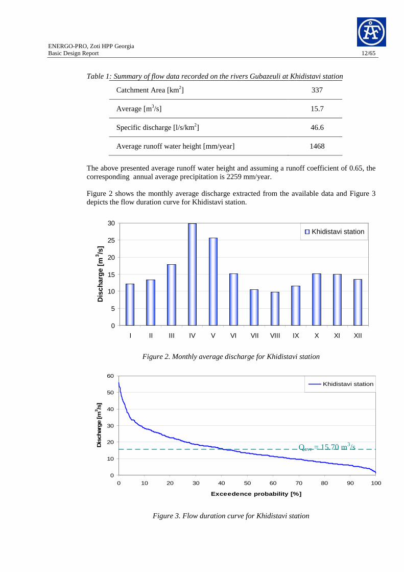
Table 1: Summary of flow data recorded on the rivers Gubazeuli at Khidistavi station
Catchment Area [km2] 337
Average [m3/s] 15.7
Specific discharge [l/s/km2] 46.6
Average runoff water height [mm/year] 1468
The above presented average runoff water height and assuming a runoff coefficient of 0.65, the corresponding annual average precipitation is 2259 mm/year.
Figure 2 shows the monthly average discharge extracted from the available data and Figure 3 depicts the flow duration curve for Khidistavi station.
0
5
10
15
20
25
30
I II III IV V VI VII VIII IX X XI XII
Dis
char
ge [m
3 /s]
Khidistavi station
Figure 2. Monthly average discharge for Khidistavi station
Figure 3. Flow duration curve for Khidistavi station
0
10
20
30
40
50
60
0 10 20 30 40 50 60 70 80 90 100
Exceedence probability [%]
Dis
char
ge [m
3/s
]
Khidistavi station
Qave = 15.70 m3/s
ENERGO-PRO, Zoti HPP Georgia Basic Design Report 13/65
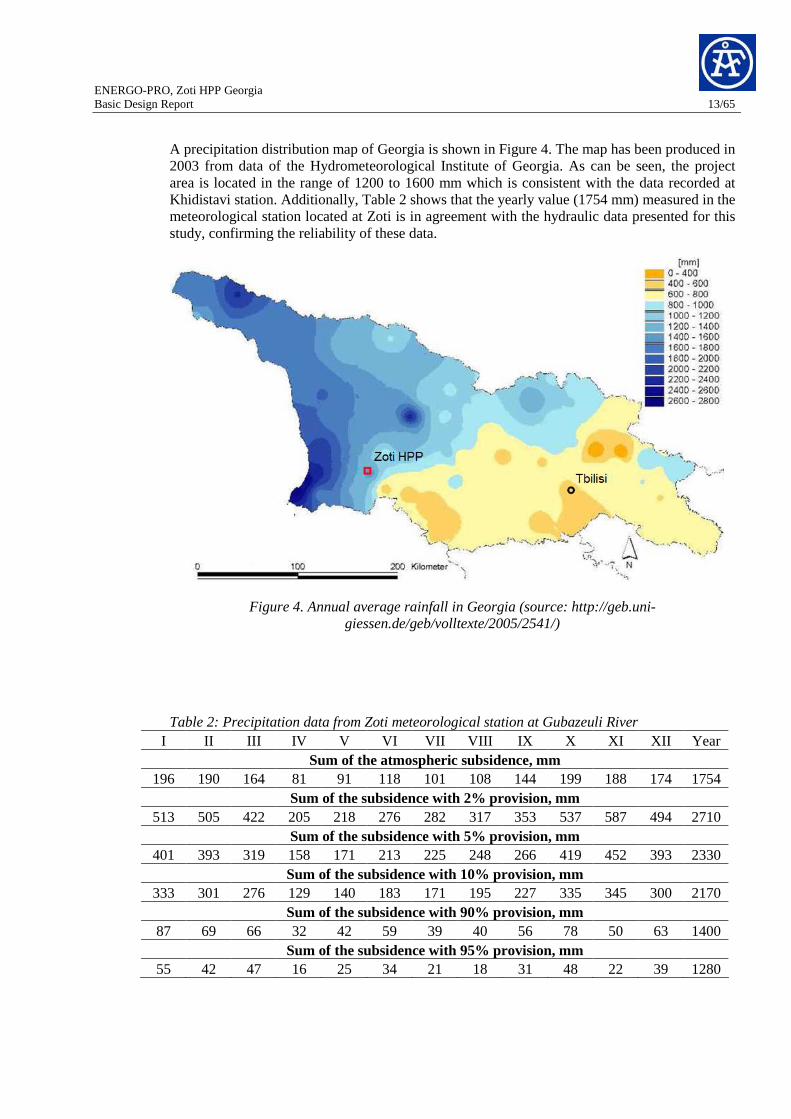
A precipitation distribution map of Georgia is shown in Figure 4. The map has been produced in 2003 from data of the Hydrometeorological Institute of Georgia. As can be seen, the project area is located in the range of 1200 to 1600 mm which is consistent with the data recorded at Khidistavi station. Additionally, Table 2 shows that the yearly value (1754 mm) measured in the meteorological station located at Zoti is in agreement with the hydraulic data presented for this study, confirming the reliability of these data.
Figure 4. Annual average rainfall in Georgia (source: http://geb.uni-giessen.de/geb/volltexte/2005/2541/)
Table 2: Precipitation data from Zoti meteorological station at Gubazeuli River I II III IV V VI VII VIII IX X XI XII Year
Sum of the atmospheric subsidence, mm 196 190 164 81 91 118 101 108 144 199 188 174 1754
Sum of the subsidence with 2% provision, mm 513 505 422 205 218 276 282 317 353 537 587 494 2710
Sum of the subsidence with 5% provision, mm 401 393 319 158 171 213 225 248 266 419 452 393 2330
Sum of the subsidence with 10% provision, mm 333 301 276 129 140 183 171 195 227 335 345 300 2170
Sum of the subsidence with 90% provision, mm 87 69 66 32 42 59 39 40 56 78 50 63 1400
Sum of the subsidence with 95% provision, mm 55 42 47 16 25 34 21 18 31 48 22 39 1280

ENERGO-PRO, Zoti HPP Georgia Basic Design Report 14/65
5.1 Inflow
As mentioned before, the station Khidistavi (150 m.a.s.l) on the Gubazeuli River has been used to estimate proportionally the water availability for the different catchments.
Zoti HPP takes the water from 4 different catchments as shown in Figure 5.
Figure 5. Catchment areas for Zoti HPP
A scale factor according to each catchment area was calculated in order to determine the different average duration curves. The main parameters of these catchments can be found in Table 3.
Table 3: Summary of the main parameters for all catchments
Catchment 1 Catchment 2 Catchment 3 Catchment 4
Tyrolean intake Khinistskali river
Gubazeuli dam Gubazeuli river
Tyrolean intake Gubazeuli Creek
Tyrolean intake Kvirilas river
Talweg level [m.a.s.l.]
1152.5 1100.0 1144.0 1144.0
Catchment Area [km2]
39.5 30.3 6.7 46
Catchment 4: Diversion Kvirilas
46.0 km2 Catchment 2:
Gubazeuli reservoir 30.3 km2
Catchment 1: Diversion Khinistskali
39.5 km2
Catchment 3: Diversion Gubazeuli Creek
6.7 km2

ENERGO-PRO, Zoti HPP Georgia Basic Design Report 15/65
Factor 0.12 0.09 0.02 0.14
Qaverage [m3/s]
1.84 1.41 0.31 2.14
The resulting duration curves for each catchment area and the Zoti HPP are showed in Figure 6.
0
1
2
3
4
5
6
7
8
9
10
11
12
13
14
15
16
17
18
19
20
21
0 10 20 30 40 50 60 70 80 90 100
Exceedence probability [%]
Dis
char
ge [m
3 /s]
Zoti HPP
Kvirilas River (third tyrolean intake)
Gubazeuli Creek (second tyrolean intake)
Gubazeuli River (Zoti Dam)
Khinistskali (first tyrolean intake)
Qaverage = 5.70 m3/s
Figure 6. Average duration curves for all catchments
5.2 Ecological water release
Ecological release has been taken into account for all diversions. The corresponding discharge is determined according to Swiss regulations, where the water inflow that reaches at least during 347 days a year (95% of dependability) is the input parameter. For Zoti HPP the total ecological release is for all catchment areas 0.64 m3/s.
5.3 Design floods
Design floods were estimated for floods up to the 1000-year event. In the project area there is no recorded data about flood events, therefore no peak values are available. Due to this lack of information, a standard determination of maximal flows is not possible. Considering that the project catchment areas are small, it has been decided to correlate values from Colenco data base from other projects in the region. The design peak values are given in Figure 7.

ENERGO-PRO, Zoti HPP Georgia Basic Design Report 16/65
SPECIFIC DESIGN FLOOD VS CATCHMENT AREA
0.00
2.00
4.00
6.00
8.00
10 100 1,000Catchment area in km 2
Spe
cific
Des
ign
flood
in m
3 /s/k
m2
Q10
Q100
Q1000
Figure 7. Assumed peak values for Zoti HPP
5.4 Sediment yield and sediment transport
Sediment yield refers to the amount of sediment exported by a basin over a period of time, which is also the amount which will enter a reservoir located at the downstream limit of the basin. Sediment estimations have been made at Khidistavi Village on Gubazeuli River where the suspended load is estimated to 138.5 t/year and the bed load to 20% of that amount. Consequently, the sediment yield at this station is 373 m3/km2/yr. It is possible to induce that sediments are not a big issue for the project. However, it is suggested to carry out watershed investigations and by mean of empirical methods the sediment yield can be calculated and compared and then should be used to plan flushing operations at the reservoir.
Sediment samples in the upstream part of the reservoir should be taken in order to elaborate a sediment transport capacity study and verify that there are not negative effects in the reservoir storage volume.
6 Design Parameters
6.1 General considerations
6.1.1 Selling prices for energy in Georgia
There are two options for selling the electricity in Georgia, through direct contracts with the qualified companies (distribution Licensees or large companies consuming more than 30 GWh per year) or sale of electricity to the Electricity System Commercial Operator (ESCO) through the balancing market. There is no difference between the peak and base energy prices.
ENERGO-PRO, Zoti HPP Georgia Basic Design Report 17/65
Normally, the selling price of electricity is established by the Georgian National Energy Regulatory Commission (GNERC) on the basis of the relevant tariff submission made by the company in accordance with the established tariff methodology. However, for new Hydro Power Plants the energy legislation envisages the possibility of concluding the long term PPA with ESCO on guaranteed purchase of the electricity. The terms of such PPA should be negotiated at the initial stage of the project approval in the relevant Memorandum of Understanding with the Government of Georgia. (Later GNERC shall approve such negotiated tariff). In case if the power plant will be constructed by JSC Energo-Pro Georgia, most likely we shall not require a compulsory purchase of electricity by ESCO but rather more sell electricity in accordance with the needs of our distribution business - use such electricity for distribution purposes, sell electricity to domestic large customers or export to the neighboring markets (pending the seasons of the year).
As the initial guidance for tariff, it might be useful to note that currently HPP Paravani, that is to be built in Georgia, has negotiated the selling price of electricity with the Government (through the Memorandum) at 4.7 US Cents per KWh of power.
The legislation does envisage selling of capacity (MW) by newly built power plants, however this part of regulations is constantly changing and therefore it is advisable that the calculations are made without envisaging the possibility of selling the capacity separately.
6.1.2 Water Usage Permission
According to information of the legal department of ENERGO-PRO, the current Law of Georgia on Licensing and Permissions does not require obtaining any license or permission for the water usage. In case the river or channel water is used for irrigation purposes, the fee for using such water is to be agreed with the owner of the channel or the water reservoir.
6.1.3 Land Acquisition
Local Municipalities are entitled to determine the normative selling price of the land and currently, according to the information from the legal department, such price for Chokhatauri Region, comprises 2.16 Gel per m2 (~0.98 Eur/m2)
6.2 Economical Parameters
6.2.1 Unit Prices and Currency
The adopted unit prices for the cost estimate for civil works and hydraulic steel structures are based on recent studies and projects situated in Albania and Georgia, with price basis 2008.
All unit prices, as well as all amounts of the cost estimate are given in Euro.
6.2.2 Site Installation
For site installation and camp construction, 15% of the civil costs are adopted.

ENERGO-PRO, Zoti HPP Georgia Basic Design Report 18/65
6.2.3 Contingencies, Environmental & Social Costs
Overall technical contingencies of 15% for civil and hydro mechanical parts and 10% for electromechanical parts are assumed.
6.2.4 Construction Period
The construction period, defined as the time span between the start of mobilization and the commissioning date of the plant, is estimated to last 3.5 years.
6.2.5 Maintenance & Operation Cost
- Maintenance costs are adopted as follows:
o Civil: 0.3%
o HSS: 0.8%
o Electrical: 0.5%
o Mechanical: 0.5%
- Operation costs are calculated assuming the following salaries:
o Management: 15’000 EUR/year
o Engineer: 12’000 EUR/year
o Technician: 700 EUR/year
o Manual: 500 EUR/year
- Insurance costs: 0.25%
- No concession fee, royalties or similar charges are assumed.
6.2.6 Concession Duration and Discount Rates
Concession duration of 50 years is adopted for the calculations of the prime costs of energy. The adopted interest rate (assumed to be the Weighted Average Cost of Capital) is 9.5% for both, construction phase and amortisation phase. The values are taken from a financial and economical study which Colenco has carried out for the Khudoni Hydropower Project on the Enguri River.
7 Power potential study
In order to evaluate the optimum installed capacity, e.g. the optimum nominal discharge, a power potential study has been carried out. The studied scenarios correspond to exceedance values of 9%, 13%, 17%, 25% and 33% from the average flow duration curve (See Figure 8).

ENERGO-PRO, Zoti HPP Georgia Basic Design Report 19/65
9, 10.7
13, 9.8
17, 8.9
25, 7.533, 6.5
0
2
4
6
8
10
12
14
16
18
20
0 10 20 30 40 50 60 70 80 90 100
Exceedence probability [%]
Dis
char
ge [m
3 /s]
Figure 8. Zoti HPP- Flow duration curve with the exceedance – discharge values for the power potential study
The elements and parameters that have been included in the power potential study are as follows:
Scheme elements:
• Catchment 1: Diversion Khinistskali + diversion tunnel + channel
• Catchment 2: Dam "Gubazeuli"
• Intake structure
• Catchment 3: Diversion Gubazeuli Greek + Diversion tunnel
• Catchment 4: Diversion Kvirila + Diversion tunnel
• Headrace tunnel
• Upstream surge shaft
• Pressure shaft
• Underground powerhouse, switch gear and transformer cavern
• Tailrace channel
Economical parameters:
a) Site Installation and Camp (only on civil costs) 15.0%
b) Contingencies for C&H parts 15.0%
c) Contingencies for E&M parts 10.0%

ENERGO-PRO, Zoti HPP Georgia Basic Design Report 20/65
Others:
• Accesses (roads, bridges, tunnels)
• Various Expenses (0.8% of the total construction and equipment costs)
• Investigations (1.0 % of the total construction and equipment costs)
• Feasibility Study, Final Design and Tendering (2.0 % of the total construction and equipment costs)
• Design, Supervision and Administration (7.0 % of the total construction and equipment costs)
• Connection to the Electrical National Grid (10 km)
All elements have been evaluated technical and economically with the same detail level. The results of the power potential study are showed in the Table 4.

ENERGO-PRO, Zoti HPP Georgia Basic Design Report 21/65
Table 4: Power potential study results
HPP "Zoti"
9% 13% 17% 25% 33%Installed capacity: 59.0 54.2 49.4 41.8 36.3
Total Construction and Equipment Cost 103 € 71,670.47 69,471.97 67,152.83 63,721.65 61,063.76 Civil 103 € 45,804.03 44,887.88 43,928.95 42,617.06 41,743.32
Hydraulic Steel Structures 103 € 3,786.07 3,633.65 3,403.35 3,026.02 2,607.26
Mechanical 103 € 8,294.11 7,837.39 7,380.67 6,676.56 6,125.13
Electrical 103 € 13,786.25 13,113.05 12,439.85 11,402.00 10,588.05
Total Cost various 103 € 20,640.41 20,402.97 20,152.51 19,781.94 19,494.89
Total Investment Cost 103 € 92,310.88 89,874.94 87,305.33 83,503.58 80,558.64
Construction Time years 3.0 3.0 3.0 3.0 3.0Interest rate during Construction (DSI) 9.5%Interest Cost 17,539.07 17,076.24 16,588.01 15,865.68 15,306.14
Total Investment 103 € 109,849.94 106,951.18 103,893.35 99,369.26 95,864.79
Interest rate (DSI) 9.5%q 1.095
Financial Evaluation Period [years]Civil 50 49.6% 49.9% 50.3% 51.0% 51.8%Hydraulic Steel Structures 50 4.1% 4.0% 3.9% 3.6% 3.2%Mechanical 50 9.0% 8.7% 8.5% 8.0% 7.6%Electrical 50 14.9% 14.6% 14.2% 13.7% 13.1%Various and Interest during Construction 50 22.4% 22.7% 23.1% 23.7% 24.2%Weighted Average 50.0 50.0 50.0 50.0 50.0Annual Depreciatoin and Interest Cost 10,548.57 10,270.21 9,976.58 9,542.14 9,205.62
Maintenance cost 278.10 268.49 258.12 242.45 229.65 Civil 103 € 0.3% 137.41 134.66 131.79 127.85 125.23
Hydraulic Steel Structures 103 € 0.8% 30.29 29.07 27.23 24.21 20.86
Mechanical 103 € 0.5% 41.47 39.19 36.90 33.38 30.63
Electrical 103 € 0.5% 68.93 65.57 62.20 57.01 52.94
Operation Cost 731.92 724.67 717.03 705.72 696.96 Personnel Cost 103 € 457.29 457.29 457.29 457.29 457.29
Management 1500 1 37.69 37.69 37.69 37.69 37.69 Engineers 1200 3 90.45 90.45 90.45 90.45 90.45
Professional 700 8 140.71 140.71 140.71 140.71 140.71 Manual 500 15 188.44 188.44 188.44 188.45 188.45
Charges 103 € 0.0%
Administration and Insurance 103 € 0.25% 274.62 267.38 259.73 248.42 239.66
TOTAL ANNUAL COST 103 € 11,558.59 11,263.37 10,951.72 10,490.31 10,132.23
Energy ProductionPeak Energy GWh 234.4 231.7 227.1 216.2 205.1Off-peak Energy GWhTotal Energy Production GWh 234.4 231.7 227.1 216.2 205.1Energy Price Peak Energy (DSI) €/MWh 34.0Energy Price Off-peak Energy (DSI) €/MWhTotal Equi. Peak Energy Production GWh 234.4 231.7 227.1 216.2 205.1
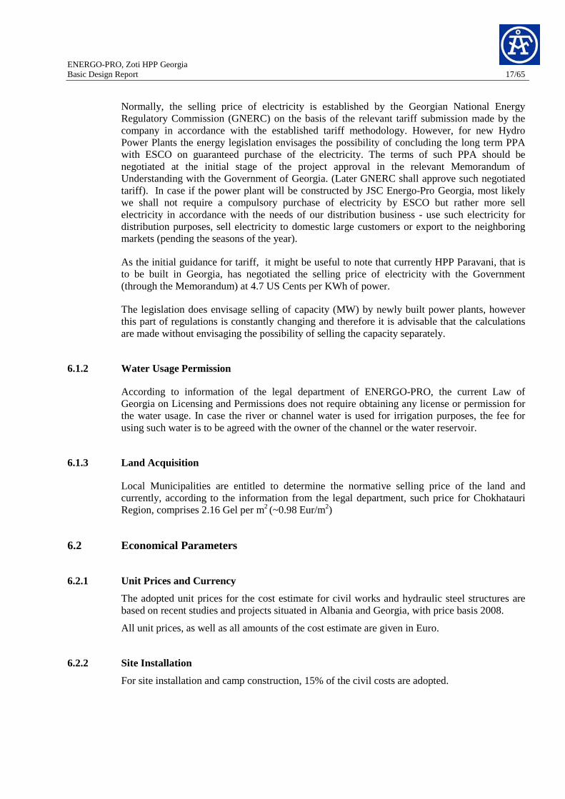
PRIME COST OF ENERGY €/MWh 49.3 48.6 48.2 48.5 49.4
A tendency curve has been derived from the prime cost of energy versus installed capacity for each scenario; consequently the calculated optimum installed capacity corresponds to a value of 48 MW. (See Figure 9)
ENERGO-PRO, Zoti HPP Georgia Basic Design Report 22/65
Figure 9. Optimum installed capacity based on a unique tariff
8 Project Layout
8.1 Salient Features
Catchment 1
Catchment area 39.5 km2
Talweg elevation 1152.5 m.a.s.l.
Intake type Tyrolean weir
Design discharge 2.80 m3/s
Outdoor desilting basin L= 60 m; Aefective= 10.15 m2; Dgrain= 0.25 mm
Qecological 0.21 m3/s
Diversion tunnel L= 2.7 km; free flow
Flood design 270 m3/s
Tunnel type Concrete lined; D-shape
Diversion Khinistskali
Tunnel section excavation 21.0 m2 (including access)
Catchment 2
Catchment area 30.3 km2
Talweg elevation 1100 m.a.s.l.
Dam type Concrete gravity
Crest elevation 1145 m.a.s.l.
Deepest foundation elevation 1103 m.a.s.l.
Dam Gubazeuli
Maximum height 42 m
49.3
48.6
48.2
48.5
49.4
48.0
48.5
49.0
49.5
34 35 36 37 38 39 40 41 42 43 44 45 46 47 48 49 50 51 52 53 54 55 56 57 58 59 60
Installed capacity [MW]
Prim
e R
ate
[EU
R /
MW
h]
Optimum installed capacity = 48 MW

ENERGO-PRO, Zoti HPP Georgia Basic Design Report 23/65
Talweg elevation 1100 m.a.s.l.
Crest elevation 1145 m.a.s.l.
Qecological 0.16 m3/s
Type Ungated-incorporated in dam
Elevation of ogee crest 1155.6 m.a.s.l.
Number of openings 2
Width of openings 14 m
Design discharge (Q1000) 250 m3/s
Max. reservoir level 1142.8 m.a.s.l.
Spillway
PMF (375 m3/s) level 1143.6 m.a.s.l.
Dimensions (w x h) 3.5 x 4.0 m
Number of openings 1 Bottom outlet
Max. capacity (full reservoir) 205 m3/s
Invert elevation 1128.8 m.a.s.l
Type Bell-mouth inlet
Design discharge 4.90 m3/s
Sliding gate (w x h) 2.3 x 1.8 m
Intake
Trash rack (w x h) 3.4 x 2.3 m
Max. reservoir level 1140 m.a.s.l.
Min. reservoir level 1131.8 m.a.s.l.
Average reservoir level 1136.5 m.a.s.l.
Total storage volume 3.415 x10⁵ m3
Live storage volume 1.858 x10⁵ m3
Reservoir Gubazeuli
Dead storage volume 1.557 x10⁵ m3
Catchment 3
Catchment area 6.7 km2
Talweg elevation 1144.0 m.a.s.l.
Intake type Tyrolean weir
Design discharge 0.50 m3/s
Flood design 75 m3/s
Outdoor desilting basin L= 25 m; Aefective= 2.1 m2; Dgrain= 0.25 mm
Qecological 0.04 m3/s
Diversion Gubazeuli Greek
Diversion tunnel L= 230 m; pressure flow
ENERGO-PRO, Zoti HPP Georgia Basic Design Report 24/65
Tunnel type Concrete lined; D-shape
Tunnel section excavation 6.8 m2
Catchment 4
Catchment area 46.0 km2
Talweg elevation 1144.0 m.a.s.l.
Intake type Tyrolean weir
Design discharge 3.2 m3/s
Flood design 275 m3/s
Underground desilting basin L= 60 m; Aefective= 12.24 m2; Dgrain= 0.25 mm
Qecological 0.24 m3/s
Diversion tunnel L= 420 m; pressure flow
Tunnel type Concrete lined; D-shape
Tunnel section excavation 6.8 m2
Diversion Kvirila
Type/section Concrete lined/D-shape
Length 8560 m
Design discharge 8.6 m3/s
Tunnel section excavation 9.23 m2
Internal tunnel section 6.10 m2
Concrete lining thickness 30 cm
Headrace tunnel
Flow velocity 1.40 m/s
Type Underground shaft
Height 45 m
Internal diameter 8.5 m
Concrete lining thickness 40 cm
Section excavation 67.90 m2
Max. surge level 1154.2 m.a.s.l.
Min. surge level 1116.7 m.a.s.l.
Top elevation 1159.2 m.a.s.l.
Upstream surge shaft
Bottom elevation 1111.2 m.a.s.l.

ENERGO-PRO, Zoti HPP Georgia Basic Design Report 25/65
Height vertical part 612 m
Length of lower horizontal part
100 m
Excavation diameter 2.8 m
Height vertical part 612 m
Internal Diameter concrete lined stretch/Length
2.2 m / 408 m
Internal Diameter steel lined stretch/Length
2.2 m / 304 m
Design discharge 8.6 m3/s
Pressure shaft
Housing Underground cavern
Turbines 2 x vertical Pelton
Turbine axes elevation 500 m.a.s.l
Nominal head 628.6 m
Average gross head 636.50
Total average head losses 7.90 m
Design discharge 8.6 m3/s
Installed capacity 2 x 24 MW
Machine efficiency 0.90
Powerhouse
Housing Underground cavern
Transformer type Three phases, Two Windings, oil filled
Capacity 30 MVA
Voltage ratio 110/10 kV
Total numbers provided 2
Transformer
Type Outdoor Open Air
Rated Voltage 110kV
Total bays provided 3 + 1 spare place Switchyard
Type/section Rectangular channel housed in a D-shape section
Length 2190 m
Design discharge 8.6 m3/s
Tailrace tunnel
Tunnel section excavation 7.30 m2

ENERGO-PRO, Zoti HPP Georgia Basic Design Report 26/65
Channel internal dimensions 2.20 x 1.80 m (w x h)
Concrete lining thickness 20 cm
Flow velocity 2.80 m/s
8.1.1 Schematic Longitudinal Profile
Figure 10. Zoti HPP- Schematic longitunal profile
8.1.2 Reservoir Management
The project has a reservoir named Gubazeuli, located on the river with the same name at an elevation of 1110.0 m.a.s.l. The water from the Khinistskali intake is diverted through the diversion tunnel and enters directly in the reservoir. Additionally, the water from the other two intakes enters directly in the headrace tunnel as long as the water reservoir is at level of 1140 m.a.s.l. (max. operation level). Otherwise, when the turbines are in off mode, and the water reservoir level is lower than the maximum operation level, the water from Gubazeuli Creek and Kvirilas intake will feed the reservoir, which maximum level is always controlled by means of the ungated spillways. The volume curve of the reservoir is depicted in Figure 10 below. The main features of the reservoir are given in Table 5.

ENERGO-PRO, Zoti HPP Georgia Basic Design Report 27/65
Zoti HPP - Reservoir Gubazeuli RESERVOIR VOLUME CURVE
1105
1110
1115
1120
1125
1130
1135
1140
1145
1150
-100,000 - 100,000 200,000 300,000 400,000 500,000 600,000
Volume [m 3]
Ele
vatio
n [m
a.s
.l.]
0
Max. operation level = 1140 m.a.s.l.
Min. operation level = 1131.8 m.a.s.l.
Figure 11. Gubazeuli reservoir – volume curve
The reservoir has a daily storage capacity and allows producing 5 hours of peak energy during 214 day in a hydrological average year with full capacity. Therefore, the annual energy production of 255 MW can be divided in 82.7 MW (peak energy) and 142.4 MW (base energy). At the moment there is no a tariff difference between peak and off peak energy, however having a reservoir in the scheme allows to generate peak energy which will be economically advantageous.
Table 5: Main features of the reservoir Gubazeuli
Maximum reservoir level 1140.0 m.a.s.l.
Average reservoir level 1136.5 m.a.s.l.
Minimum reservoir level 1131.8 m.a.s.l.
Maximum water level for the design flood 1143.6 m.a.s.l.
Total storage volume 3.415x10⁵ m3
Live storage volume 1.858x10⁵ m3
Dead storage volume 1.557x10⁵ m3
There is no information about sediment transport at the Gubazeuli River; therefore an estimate of sediments entering in the reservoir has not been possible. However, in order to keep the life initial life storage, we strongly recommend to envisage periodical flushing operations, e.g. once or twice a year after heavy rain storms.

ENERGO-PRO, Zoti HPP Georgia Basic Design Report 28/65
8.1.3 Installed Capacity and Energy Production
The design discharge of 8.60 m3/s of the Zoti HPP has been determined according to the power potential study. The total inflow volume (diverted from the four catchments) is 179.8 x10⁶ m3 and the harnessed volume is 146.0 x10⁶ m3.
With the chosen design discharge and the maximum net head of 640 m, an installed capacity of 48 MW results. The foreseen underground powerhouse will be equipped with two groups (Pelton turbines), 24 MW each.
In an average hydrological year, the average annual energy production would be 225.1 GWh.
8.2 Civil Engineering Structures
8.2.1 Diversion Khinistskali
8.2.1.1 Intake and Desilting Facilities
Khinistskali tyrolean intake is the most upstream intake structure of the project and it is designed to divert 2.8 m3/s of the Khinistskali River.
The Tyrolean or drop intakes are commonly used for small and steeply sloped mountain rivers with competent rock foundation. This type of intake, used in the absence of a reservoir, consists essentially of a channel built in the river bed, stretching across it and protected by a trashrack with a sloping face oriented in the direction of the river flow (Figure 12). Particles which are smaller than the inside width between the trashrack bars are introduced into the collection canal together with the water and these will be later on be separated from the water by a first sediment trap for coarse material and afterwards by a desilting basins for fine material.
Figure 12. Tyrolean intake
The structure is also composed of an ungated spillway next to the tyrolean intake to pass by the floods up to a return period of 1000 years.
The main features of this diversion are described in Table 6.

ENERGO-PRO, Zoti HPP Georgia Basic Design Report 29/65
Table 6: Main features of the diversion Khinistskali
Talweg elevation 1152.5 m.a.s.l.
Top elevation of trash rack 1153.9 m.a.s.l.
Intake width grid 2 m
Design discharge 2.8 m3/s
Flood Capacity 275 m3/s
Elevation of ogee crest (spillway) 1155.6 m.a.s.l.
Effective spillway length 4 x 9.00 m
Minimum diameter to be settled out in the desander facility
0.25 mm
Length of desander chamber (including transition zone and valve chamber)
60 m
Dimensions of effective desander space (width x height) 2.90 x 3.50
8.2.1.2 Diversion Tunnel Khinistskali
The diversion tunnel connects the Khinistskali intake structure to the reservoir Gubazeuli, located on the Gubazeuli River. The tunnel is located on the left side bank of the intake structure and has a length of 2700 m. This tunnel during construction serves as a main adit for the construction of the Khinistskali intake, later on it will become a water way and a permanent maintenance access. The section is a D-shape type. The excavated width at the invert is 3.4 m, the vertical banks are 1.85 m high and the top arch has a radius of 1.7 m. A concrete lined channel will be placed on the left side of the tunnel, leaving 2.3 m on the other side as permanent maintenance access way after construction. The invert will be lined with a 30 cm thick concrete, while the arch and one vertical sidewall will be protected with shotcrete and wire mesh where required by geological conditions. The tunnel invert is at an elevation of 1148.80 m a.s.l at the inlet and 1140 m a.s.l at the outlet, resulting in a constant slope of 0.3 % until reaching the reservoir. The construction method, whether conventional or with a tunnel boring machine (TBM) will be decided at a later design stage. Drawings annexed to this report shall be consulted for additional geometry details.
8.2.2 Gubazeuli Dam and Intake
8.2.2.1 Dam Type
The Gubazeuli Dam is a concrete gravity dam type of 42 m height. The main parameters are described in Table 6:

ENERGO-PRO, Zoti HPP Georgia Basic Design Report 30/65
Table 7: Main features of the Dam Zoti
Talweg elevation 1110 m.a.s.l.
Crest elevation 1145 m.a.s.l.
Deepest foundation elevation 1103 m.a.s.l.
Maximum height 42 m
The form of the valley at the dam axis is favourable for a simple gravity dam. Due to the factthat the flood design discharge is not very high (250 m3/s) and that the dam crest is long enough, two ungated spillway structures can be easily integrated within the dam body. In addition, the incorporation of the bottom outlet or sluice way (3.50 x 4.00 m) in the dam body represents no major challenge.
The estimated volumes for the gravity dam are:
Table 8: Estimated main volumes for Gubazeuli dam
Concrete volume 45'214 m3
Excavation volume 21'295 m3
Foundation surface 2'770 m3
Clearing surface 5'435 m3
The foundation treatment will consist of contact and consolidating grouting over the whole foundation surface (both abutments and the central part below the river) and of a grout curtain with a depth in the central part of ~25 m. Downstream of the grout curtain drainage holes will be provided.
Spillway
The spillway consists of an ungated overflow spillway with a total crest length of 28.0 m. A bridge over the spillway will be provided by dividing the overfall section into 2 openings of 14 m each, separated by a pier of 2.0 m. The pier also contributes to aeration of the flow. Sill elevation is 10 cm above the maximum operation level at 1140 m.a.s.l.
With the peak design discharge of 250 m3/s (Q1000) the maximum reservoir level will rise up to an elevation of 1142.8 m.a.s.l. and during probable maximum flood conditions (PMF = 375 m3/s) to 1143.6 m.a.s.l. with a free board of 1.4 m.
Bottom Outlet
One bottom outlet is integrated into the right part of the dam body. This bottom outlet has not flood purposes but rather sediment flushing operations. The frequency of the reservoir flushing should be determined during the operation according to the sediment inflows. At this stage we do not have any sediment information at the dam location. The invert elevation of the bottom outlets is at a level of 1118 m.a.s.l., i.e. ~1 m above the original ground level (talweg). It serves also to empty the reservoir in an emergency case.
ENERGO-PRO, Zoti HPP Georgia Basic Design Report 31/65
The bottom outlet consists of: a bell-mouth inlet, a pressured conduit, a sliding gate 3.5 x 4.0 m (w x h), a set of stoplogs and a flip bucket.
The bell-mouth inlet and pressurized conduit will be fully steel-lined. Downstream of the gates, the invert and side walls of the free flow channel up to 1 m from the invert, will be also steel-lined. This is to prevent damage to the concrete during emptying of the reservoir. The thickness of the steel lining should not be less than 20 mm.
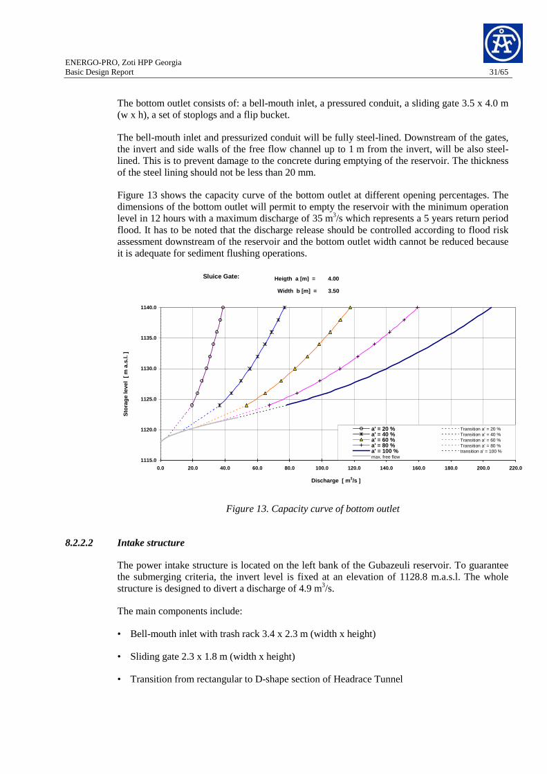
Figure 13 shows the capacity curve of the bottom outlet at different opening percentages. The dimensions of the bottom outlet will permit to empty the reservoir with the minimum operation level in 12 hours with a maximum discharge of 35 m3/s which represents a 5 years return period flood. It has to be noted that the discharge release should be controlled according to flood risk assessment downstream of the reservoir and the bottom outlet width cannot be reduced because it is adequate for sediment flushing operations.
1115.0
1120.0
1125.0
1130.0
1135.0
1140.0
0.0 20.0 40.0 60.0 80.0 100.0 120.0 140.0 160.0 180.0 200.0 220.0
Discharge [ m 3/s ]
Sto
rage
leve
l [ m
a.s
.l. ]
a' = 20 % Transition a' = 20 %a' = 40 % Transition a' = 40 %a' = 60 % Transition a' = 60 %a' = 80 % Transition a' = 80 %a' = 100 % transition a' = 100 %max. free flow
Sluice Gate: Heigth a [m] = 4.00
Width b [m] = 3.50
Figure 13. Capacity curve of bottom outlet
8.2.2.2 Intake structure
The power intake structure is located on the left bank of the Gubazeuli reservoir. To guarantee the submerging criteria, the invert level is fixed at an elevation of 1128.8 m.a.s.l. The whole structure is designed to divert a discharge of 4.9 m3/s.
The main components include:
• Bell-mouth inlet with trash rack 3.4 x 2.3 m (width x height)
• Sliding gate 2.3 x 1.8 m (width x height)
• Transition from rectangular to D-shape section of Headrace Tunnel

ENERGO-PRO, Zoti HPP Georgia Basic Design Report 32/65
The size of the trash rack opening results in an intake net velocity of about 1.0 m/s. The minimum operation water level at an elevation of 1131.8 m.a.s.l. ensures that the water inflow in the bell-mouth inlet is free from vortices and air entrainment.
The top level of the intake structure has an elevation of 1145 m.a.s.l., equivalent to that of the dam crest. This also allows access during floods. Access to the top platform of the structure is by a road coming from the dam crest.
At elevation 1143.2 m.a.s.l. the gate shaft is enlarged to a chamber for maintenance works of the sliding gate.
In the very low probability case that the Gubazeuli Creek and Kvirilas intakes are diverting only 16% of their corresponding design discharge into the system, the intake structure will experiment higher velocities compared to the design ones. For example, assuming than Gubazeuli Creek and Kvirilas intake divert together only 0.6 m3/s (instead of 3.70 m3/s) the velocity through the intake tunnel entrance will rise to ~4.6 m/s (~64 % more) and the gross velocity through the trash rack will increase to ~1.10 m/s (~70% more) for a discharge of 8.0 m3/s. Even these values are in the upper limit, they are still acceptable for non-frequent cases.
8.2.3 Diversion Gubazeuli Creek
8.2.3.1 Intake and Desilting Facilities
Gubazeuli Creek includes a tyrolean type intake and it is designed to divert 0.5 m3/s. The description of this intake structure and of the desilting facilities corresponds to that one given in chapter 8.2.1.1.
The structure is also composed of an ungated spillway next to the tyrolean intake to pass the floods up to a return period of 1000 years.
The main features of this diversion are described in Table 9.
Table 9: Main features of the diversion Gubazeuli Creek
Talweg elevation 1144.0 m.a.s.l.
Top elevation of trash rack 1144.5 m.a.s.l.
Design discharge 0.5 m3/s
Flood Capacity 75 m3/s
Elevation of ogee crest (spillway) 1146.25 m.a.s.l.
Effective spillway length 2 x 9.00 m
Minimum diameter to be settled out in the desander facility
0.25 mm
Length of desander chamber (including transition zone and 25 m
ENERGO-PRO, Zoti HPP Georgia Basic Design Report 33/65
valve chamber)
Dimensions of effective desander space (width x height) 1.40 x 1.50
8.2.3.2 Diversion Tunnel GubazeuliCreek
The diversion tunnel connects the Gubazeuli Creek intake structure to the main headrace tunnel at 7.65 km from the surge shaft. The tunnel is located on the right side bank of the intake structure and has a length of 230 m. The section is a D-shape type. The excavated width at the invert is 2.6 m, the vertical walls are 1.60 m high and the top arch has a radius of 1.3 m. A 30 cm thick concrete lining will be placed in the entire perimeter. The diversion tunnel invert has an elevation of 1140.6 m a.s.l at the inlet and 1127 m a.s.l at the downstream connection to the main tunnel, having a slope of 5 %. The construction method, whether conventional or with a raise drill machine will be decided in a later design stage. Drawings annexed to this report shall be consulted for additional geometry details.
8.2.4 Diversion Kvirilas
8.2.4.1 Intake and Desilting Facilities
Kvirilas tyrolean intake is the last water intake of the scheme. It is designed to divert 3.20 m3/s. The description of this intake structure corresponds to that one given in chapter 8.2.1.1. The desilting facility has the same concept as the previous intakes but because of the narrow river bed and steep banks, it will be built underground.
The desilting basin tunnel is 85 m long and the flushing tunnel is 30 m long. From the end of the flushing tunnel a concrete lined channel brings the mixture water-sediment back to the river. For more details please refer to the drawings annexed to this report.
The structure is also composed of an ungated spillway next to the tyrolean intake to pass by the floods up to a return period of 1000 years.
The main features of this diversion are described in Table 10.
Table 10: Main features of the diversion Kvirila
Talweg elevation 1144.0 m.a.s.l.
Top elevation of trash rack 1145.0 m.a.s.l.
Design discharge 3.2 m3/s
Flood Capacity 270 m3/s
Elevation of ogee crest (spillway) 1146.1 m.a.s.l.
Effective spillway length 3 x 7.00 m
Minimum diameter to be settled out in the desander 0.25 mm

ENERGO-PRO, Zoti HPP Georgia Basic Design Report 34/65
facility
Length of desander chamber (including transition zone and valve chamber)
60 m
Dimensions of effective desander space (width x height) 3.40 x 3.60
8.2.4.2 Diversion Tunnel Kvirilas
The diversion tunnel connects the Kvirila intake structure to the main headrace tunnel at 4 km from the surge shaft. The tunnel is located on the right side bank of the intake structure and has a length of 420 m. The section is a D-shape type. The excavated width at the invert is 2.6 m, the vertical walls are 1.60 m high and the top arch has a radius of 1.3 m. A 30 cm thick concrete lining will be provided at the entire perimeter. The diversion tunnel invert has an elevation of 1135.45 m a.s.l at the inlet and 1116.6 m a.s.l at the connection to the main tunnel, having a slope of 8 %. The construction method, whether conventional or with a raise drill machine will be decided in a later design stage. For more details please refer to the drawings annexed to this report.
8.2.5 Headrace tunnel
The headrace tunnel connects the intake structure, situated at Gubazeuli reservoir, to the pressure shaft at its lower end. It is designed to conduct a total discharge of 8.6 m3/s with a velocity of 1.6 m/s and the head loss due to friction is 6 m, adopting a roughness of 0.0035 m. It is located on the left side of the Gubazeuli River and has a length of 8,560 m.
The excavation is a D-shape type for all profile types (See Table 11). The excavated width at the invert is 3.0 m, the vertical walls are 1.90 m high and the top arch has a radius of 1.50 m. A 30 cm thick concrete lining will be provided at the entire perimeter. The internal area of the headrace tunnel has been defined according to construction criteria and not according to an optimization of its hydraulic parameters.
From the intake, the tunnel is aligned in northwest direction until the top of the pressure shaft. The invert is situated at an elevation of 1128.8 m.a.s.l. at the intake structure and continues with a slope of 0.18 % downwards to the top of pressure shaft which is situated at an elevation of 111.2 m.a.s.l.
Table 11: Headrace tunnel profile types
Profile Type Rock quality Distribution [%]
1 Very good / good rock 30
2 Fair rock 30
3 Poor rock 35
4 Very poor rock 5
ENERGO-PRO, Zoti HPP Georgia Basic Design Report 35/65
For constructive purposes, the construction of an intermediate 850 m long adit is foreseen. This adit entrance will be situated in the access road between Zoti and Kivirila intake at an elevation of 1150 m.a.s.l. The dimensions are the same as for the headrace tunnel and the support works should be decided based on geological conditions.
8.2.6 Upstream Surge Shaft
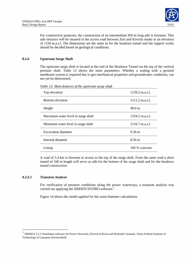
The upstream surge shaft is located at the end of the Headrace Tunnel on the top of the vertical pressure shaft. Table 12 shows the main parameters. Whether a sealing with a grouted membrane system is required due to geo-mechanical properties and groundwater conditions, can not yet be determined.
Table 12: Main features of the upstream surge shaft
Top elevation 1159.2 m.a.s.l.
Bottom elevation 1111.2 m.a.s.l.
Height 48.0 m
Maximum water level in surge shaft 1154.2 m.a.s.l.
Minimum water level in surge shaft 1116.7 m.a.s.l.
Excavation diameter 9.30 m
Internal diameter 8.50 m
Lining 100 % concrete
A road of 5.4 km is foreseen to access to the top of the surge shaft. From the same road a short tunnel of 160 m length will serve as adit for the bottom of the surge shaft and for the headrace tunnel construction.
8.2.6.1 Transient Analysis
For verification of pressure conditions along the power waterways, a transient analysis was carried out applying the SIMSEN HYDRO software.1
Figure 14 shows the model applied for the water-hammer calculations.
1 SIMSEN V2.3 Simulation software for Power Networks, Electrical drives and Hydraulic Systems. Swiss Federal Institute of Technology of Lausanne (Switzerland)

ENERGO-PRO, Zoti HPP Georgia Basic Design Report 36/65
Figure 14. Schema of the numerical model for transient analysis of Zoti HPP
The most hazardous cases of transient operations of the power-plant have been studied as follows:
For maximum upsurge level in the surge tank:
• Case-1: Emergency stop of both units simultaneously, at maximum reservoir level
• Case-2: Start up of both units followed by emergency stop of both units at the worst instant, maximum reservoir level
For maximum downsurge level in the surge tank:
• Case-3: Emergency stop of both units followed by start up of the units at the worst instant (one by one), minimum reservoir level
• Case-4: Start up of both turbines at minimum reservoir level
Table 13: Studied operating conditions
Operating Conditions U/s Reservoir Level (m.a.s.l.)
Case-1: Emergency stop (15 sec) 1140.0
Case-2: Start up followed by emergency stop 1140.0
Case-3: Emergency stop followed by start up 1131.8
Case-4: Start up (30 sec) 1131.8
Based on the results of transient analysis, maximum upsurge level in surge shaft is 1154.2 m.a.s.l. and max downsurge is 1116.7 m.a.s.l. Pressure in penstock at bifurcation level reaches 67 bar. Results of the analysis of all four cases are presented in Table 13.

ENERGO-PRO, Zoti HPP Georgia Basic Design Report 37/65
Table 14: Results of transient calculations for the studied cases
Upsurge Downsurge Pressure shaft
(min) Pressure in
penstock (max) Operating conditions
[m.a.s.l.] [m.a.s.l] [m] [m]
Case-1 1151.3 1131.8 20.76 661.84
Case-2 1154.2 1124.9 13.57 665
Case-3 1137.5 1117.8 6.5 644
Case-4 1131.8 1116.7 5.37 638.6
Figures 4 to 5 show the variation of water level in the surge shaft as well as the maximum pressure which can be reached in the penstock for the most hazardous cases.
Figure 15. Max upsurge (red line) for case-2 and max downsurge (blue line) for case-4

ENERGO-PRO, Zoti HPP Georgia Basic Design Report 38/65
Figure 16. Max pressure in the steel lining (at bifurcation level) for case-2
8.2.7 Pressure Shaft and Valve Chamber
A pressure shaft connects the downstream end of the headrace tunnel to the powerhouse. Its main features are presented in Table 15.
Table 15: Main features of the pressure shaft
Height vertical part 612 m
Length of lower horizontal part 100 m
Excavation diameter 2.8 m
Internal Diameter concrete lined stretch/Length 2.2 m / 408 m
Internal Diameter steel lined stretch/Length 2.2 m / 304 m
Nominal discharge 8.60 m3/s
Thickness concrete lining upper part 30 cm
Thickness concrete lining lower part 26 cm
Thickness steel lining lower part 40 mm
The vertical shaft with a total height of 612 m (408 m concrete lining and 204 m steel lining) will be followed by a 90° bend at the bottom of the shaft where a 100 m horizontal steel lining

ENERGO-PRO, Zoti HPP Georgia Basic Design Report 39/65
stretch (including the bifurcation) will feed the two turbines in the underground powerhouse. The resulting head losses in the pressure shaft are 1.20 m. The lengths for the different pressure shaft stretches have to be verified in a next phase when geological information is available, including ground water table conditions.
The present basic design does not foreseen a valve chamber before the pressure shaft, given that the following pressure structure is developed fully underground and therefore, the risk to human life and goods is negligible. Whether a valve chamber will be convenient for operational and maintenance purposes should be evaluated in the next design phase according to the power plant operator. In this case, it should be located before the pressure shaft starts and the foreseen adit for construction purposes, as nominated in chapter 8.2.6 becomes a permanent access for maintenance purposes.Power Plant Equipment
8.2.8 Underground Powerhouse and Transformer cavern
The powerhouse is located in an underground cavern on the left bank of the Gubazeuli River between the villages Kvabga and Zoti. It houses two vertical Pelton turbines of 24 MW each.
The transformer is located parallel to the powerhouse in a separate cavern for security reasons. The distance between the caverns is 50 m. The access tunnel arrives first to the transformer cavern and later on to the powerhouse cavern. Additionally, a second tunnel is foreseen to interconnect both caverns and it could also serve as an emergency exit.
Table 16: Main features of the Underground Powerhouse and transformer cavern
Dimensions of the main cavern (L x W x H) 44 x 20 x 24 m
Foundation elevation 490.30 m.a.s.l.
Machine hall floor elevation 506.00 m.a.s.l.
Turbine setting level 500.00 m.a.s.l.
Top elevation of the calotte 521.30 m.a.s.l.
Dimensions of the transformer cavern (L x W x H) 38 x 11 x 12 m
8.2.8.1 Multipurpose access tunnel
The access to the powerhouse complex is through a 1 km long multipurpose access tunnel. Its portal has an elevation of 540.0 m.a.s.l. after crossing the first bridge over the existing road between Kvabga and Zoti. This is an existing bridge with 55 m length but a refurbishing is foreseen in order to support the loads of the equipments and powerhouse elements. The length of this access tunnel is 1.3 km with a slope of 4.5 %. The section is a D-shape with an excavated width at the invert of 3.0 m, the vertical walls are 1.90 m high and the top arch has a radius of 1.50 m. A 10 cm shotcrete lining is foreseen for the vertical walls and the top arc, and a 15 cm asphaltic cement layer will be placed on the invert together with a drainage system to guarantee the traffic circulation.

ENERGO-PRO, Zoti HPP Georgia Basic Design Report 40/65
Additionally, this access tunnel will port the outgoing high voltage cables placed on cable-trays at one of the banks. Cable-trays need a sectional area of 1.2 m height x 0.4 m width inside the tunnel. Closed ducts for fresh and waste air from the ventilation system have to be considered.
8.2.8.2 Tailrace tunnel
The tailrace tunnel discharges the water from the Pelton turbines and brings them back to the Gubazeuli River. The outlet portal is located at 490 m.a.s.l., near the village of Kvabga. It has a D-shape profile with a length of 2.19 km and a slope of 0.25 %. The excavated width at the invert is 2.6 m, the vertical walls are 1.80 m high and the top arch has a radius of 1.3 m. The vertical walls and the invert will form a channel with a 20 cm thick concrete. The top arc will be supported according to the profile type. This channel is designed for a discharge of 8.6 m3/s with a velocity of 2.8 m/s and a water depth of 1.40 m.
If the tunnel driving will be conventional or with a tunnel boring machine will be fixed in a later design stage.
8.2.9 Mechanical Equipment
Zoti HPP is a high head scheme with storage capacity aimed to operate mainly for peak energy production. The plant discharge is 8.6 m3/s and the maximum net head 628.6 m. Pelton turbines have been considered for operation in this range of head. Head and discharge lead to a rated turbine power of 48 MW.
8.2.9.1 Number of units and units arrangement
The installation of two units is recommended for Zoti HPP in order to achieve good availability of turbines during maintenance/repair works and in case of one turbine is out of order. Therefore turbine rated power is proposed with 2 x 24 MW.
The arrangement of the turbines is mainly determined by the costs of the cavern works. Vertical Pelton units with several injectors (more than 2 injectors) allow a more compact design than horizontal units (maximum 2 injectors).
Other advantages of vertical units by regards of horizontal units are:
• Vertical units with higher number of jets can provide better efficiencies at minimum plant discharge.
• Periodic inspection of the runner, nozzles and deflectors can be achieved at a glance, as no elements hide another (visit from below).
• Stress on Pelton runners with en even number of nozzles is cancelled as nozzles are symmetrically distributed.
A disadvantage of the vertical arrangement will be the maintenance of generator as more work is needed than for a horizontal arrangement.
Based on the above explanations, vertical Pelton arrangement is recommended for Zoti HPP.

ENERGO-PRO, Zoti HPP Georgia Basic Design Report 41/65
In order to reach a compact vertical design of each generating unit, only two bearings for the complete shaft will be installed: one upper combined thrust/guide bearing on top of the generator and a lower guide bearing on top of turbine housing. The Pelton runner is bolted directly to the lower generator shaft.
The generator frame will support the upper combined bearing. Below the generator, a large bracket embedded in the concrete will bear the generator. Axial forces will be transmitted through stator frame, to the bracket then into the concrete.
8.2.9.2 Rotating speed
For the turbine vertical arrangement two alternatives are possible: units equipped with 4 injectors (n=750 rpm) and units equipped with 6 injectors (1000 rpm).
However, the alternative with a speed rotation of n=750 rpm is recommended to avoid high runaway speed then limiting the mechanical stresses in the rotating parts.
8.2.9.3 Modes of operation
• Normal operation of the plant for peak energy production.
• Synchronous condenser mode (if foreseen by the Client): This operation is aimed to regulate the voltage of the grid by producing / absorbing reactive power. This operation needs the permanent operation of the auxiliaries including cooling water system without water contribution from the waterway (injectors closed). The cooling water concept shall take this into account if this mode of operation is foreseen.
• Spinning reserve: Pelton units are favourable for this operation mode due to capability of fast power regulation according to the grid demand. This operation is normally foreseen for powerplants equipped with Pelton units.
8.2.9.4 Turbine and governor
The main data of the turbines are:
• Type: Vertical Pelton unit
• Number of turbines: 2
• Turbine plant discharge: 8.6 m3/s
• Rated net head: 628.6 m
• Max turbine output: 48 MW
The main scope of the supply for each unit includes:
• 1 Pelton runner
• 1 turbine housing

ENERGO-PRO, Zoti HPP Georgia Basic Design Report 42/65
• 4 jet Pelton distributor
• 4 nozzles with servomotors and deflectors
• 1 turbine governor system with oil pressure unit
• Instrumentation, vibration monitoring and piping
8.2.9.5 Main Inlet Valve
The Main Inlet Valve (MIV) will be installed between the steel lined feeder and the inlet pipe of the turbine distributor. Due to the high head, the MIV is of the spherical valve type, provided with a downstream service seal and an upstream maintenance seal. This double seal concept allows inspection and maintenance works on the turbine, as well as removal of the service seal of the MIV without emptying the upstream waterway.
On the upstream side, the MIV will be flanged and bolted to a conical connection pipe, which is welded to the steel lined feeder including a make-up piece.
The opening of the MIV will be operated by means of a servomotor whereas the closing will be performed by a counterweight. One hydraulic servomotor, supported on the concrete ground shall be installed for opening the valve rotor. The oil pressure for opening will be supplied by the oil pressure system of the MIV.
The MIV consists of the following components (for each unit):
• Spherical valve, diameter approx. 700 mm, complete with body, rotor, maintenance and service seal
• Maintenance free bearings
• Servomotor and oil pressure system
• By-pass system
• Dismantling pipe and upstream connection pipe
• Counterweight with lever
8.2.9.6 Cooling Water System
The cooling water system will provide cold water to the heat exchangers of generators and transformers as well as cooling water for generator combined thrust/guide bearings and for the lower guide bearings.
The system consists of:
• Three pumps (one for each unit and one as stand-by pump) pumping water from a common sump built at the discharge pit level.

ENERGO-PRO, Zoti HPP Georgia Basic Design Report 43/65
• Two automatic backwash strainers (one as stand-by), provide continuous cleaning of water prior to entering the heat exchangers.
• Header pipes.
• Check valves installed after pump exit prevent flow back to the pumps.
• Gate valves, ball valves.
• Set of controls and instruments.
Other alternatives for cooling water system can be studied in the next stage.
8.2.9.7 Drainage and Dewatering System
The system will allow the collecting of seepage, leakage, drainage and oil contaminated water from the powerhouse cavern. The system will also allow dewatering of the turbine distributor and waterways to perform repair works of water wet parts.
Leakage, seepage, drainage and oil contaminated water of powerhouse cavern will be collected into an oil/water separator tank before directing the water by gravity to the tailrace channel. The oil/water separator tank will be installed below the MIV floor level.
Dewatering of the upstream waterway and turbine distributor will be performed directly by gravity into the tailrace channel by means of isolating valves or through injectors-deflectors at small discharge.
The system will consist of:
• One oil / water separator tank
• Dewatering header pipes
• Isolating valves
8.2.9.8 Powerhouse Crane
The powerhouse crane will provide the facility of unloading, shifting and loading of equipments in powerhouse during erection period. It will also provide the same facility during operation and maintenance periods.
The heaviest component to be lifted is the generator rotor of approx. 60 tons. Therefore the capacity of the main hook will be 70 ton whereas the capacity of the auxiliary hook will be 10 ton.

ENERGO-PRO, Zoti HPP Georgia Basic Design Report 44/65
8.2.10 Electrical Equipment - Generators, Transformers, and Switchgear
8.2.10.1 Generators
Two vertically arranged generators directly coupled with turbines shall be provided with the main features as follows:
- Number of Phases 3 Phase
- Frequency 50 Hz ± 5%
- Rated voltage 10 kV ± 10%
- Power factor 0.8
- Rated continuous capacity 30 MVA
- Speed 750 rpm
- Inertia constant approx 22’000 kg m2
The generator will consist of the following main components
- Rotor consisting of 10 laminated poles fitted in rotor rim.
- Stator with a core made of high quality lamination and a class F insulated winding
- Brake ring fixed on the rotor rim.
- Upper combined thrust and guide bearing.
- Lower guide bearing.
- Brakes / jacks with oil hydraulic and air pressure equipment.
- Slip ring assembly.
- Water cooled heat exchangers.
- Piping and supports for inlet and outlet cooling water.
- RTD’s in winding, metal and oil bearing with cable terminated in junction boxes.
- Vibration monitoring.
8.2.10.2 Excitation System
The excitation system shall provide field current to the rotor poles for producing magnetic flux. Simultaneously, a built-in Automatic Voltage Regulator shall control the field current to induce voltage at the stator terminals in accordance with the reference voltage.
ENERGO-PRO, Zoti HPP Georgia Basic Design Report 45/65
A static excitation system with thyristor rectifier shall be used in order to achieve a system with a very high response to grid fluctuation and low maintenance. Each unit should have its own static excitation equipment.
Static excitation equipment for one unit shall consist of following components:
- Regulation Cubicle consisting of one microprocessor based hardware, interface power supply and associated software. Automatic voltage regulator equipped with reference value setting, V / F limiter and reactive current compensator. Rotor current limiter, under current excitation limiter and field breaker.
- Excitation Transformer
- Slip ring with carbon brushes with associated cable to interconnect the static exciter with rotor
8.2.10.3 Generator Step-Up Transformer
The generator transformer shall step up the generator voltage to the level of transmission line, 110kV depending on the load supply configuration. Each generator will have an independent three phase 2 windings transformer.
The step-up transformer equipment consists of the following supply components:
- Type Three phases, Three Windings, oil filled
- Capacity 30 MVA
- Voltage Ratio 110/10 kV
- Type of cooling Oil Forced Water Forced (OFWF)
- Total numbers provided 2
- Terminal 110kV Connected to the 110kV switchyard with XLPE Cables
- Terminal 10kV Connected to the generator with 10 kV XLPE Cables
In order to provide a high level of reliability, we recommend separating each generator and the network by means of the step-up transformer.
A direct connection as shown in the previous feasibility study shall be avoided as it could result in major damages on the stator winding in case of earth fault.
A step-up transformer spare part has not been included in the price estimation. This can be evaluated in the next stage.
8.2.10.4 Electrical Protections
The electrical protection will be assumed by redundant multifunction digital relays. The electrical protection will be separate in the following area:
ENERGO-PRO, Zoti HPP Georgia Basic Design Report 46/65
- Unit (Generator, and Main Transformer)
- 110kV Cables
- 110kV Switchyard
- Transmission Line
Definition of protective functions will be made at tender design phase according to the current practice and the recommendation of standardization institute.
8.2.10.5 Medium Voltage Switchgear
One metal-clad switchgear per unit shall be installed in the powerhouse cavern for interconnecting the generator, the excitation transformer, the auxiliary transformer and the main transformer. Off-load, de-energized type switch will be used for separate the generator in order to be able to supply the auxiliary transformer through the main transformer when the unit is not running. SF6 circuit breaker will provide fast isolating of the auxiliary transformer in case of electrical fault. Manually operated disconnecting and earthing switch shall be installed for commissioning and maintenance purpose. Each of them will be equipped with:
- 1 bay for connection to the step-up transformers
- 1 bay for connection to the auxiliary transformers (with circuit breaker)
- 1 busbar off-load switch
- 1 bay for connection to the generator
- 1 bay for connection to the excitation transformer
8.2.10.6 High Voltage Switchyard (110kV)
One outdoor switchyard shall be installed near the entrance of access gallery for interconnecting the main transformers with the transmission lines. SF6 circuit breaker will be used for synchronization process and protection of the units and transmission lines and also for switching operation.
The 110kV switchyard will be equipped with:
- 2 bays for connection to the step-up transformers
- 1 bay for connection to the transmission line
The switchyard will be designed to allow easy future extension of at least one bay for connection to the future Hydro Power Plant Kvirila
Connection between the main transformers and the switchyard will be provided by one kilometer length 110kV XLPE insulated cables and located in the access gallery.

ENERGO-PRO, Zoti HPP Georgia Basic Design Report 47/65
8.2.10.7 Low Voltage AC Supplier
One auxiliary transformer 10/0.4kV per unit shall be used to supply the plant auxiliary power. Each transformer shall be dimensioned to provide the complete auxiliary load of the plant.
The LV power distribution shall be constituted of one main distribution board and four sub distribution boards. The main distribution board shall collect the power from the auxiliary transformers or the diesel generator and shall supply the sub distribution boards. The feeders will be equipped with withdrawable circuit breaker with over current relay. The busbar shall be equipped with over/under frequency relays and over/under voltage relays as protection purpose.
One sub distribution board shall be installed for each unit, one for the general consumers in main cavern and one for the consumers in transformer cavern. The feeders shall be equipped with Circuit Breaker and over current relay, Moulded-Case Circuit Breaker (MCCB), or Miniature Circuit Breaker (MCB) depending of their nominal power. Some feeders will be equipped with additional relays for command.
Each of these five boards shall have two sections, one supplying the normal load which will be not supply by the EDG and the second the essential load which required supply by the EDG.
To supply power to the essential auxiliaries and to enable black start condition, a 200 KVA, 415V Emergency Diesel Generator (EDG) shall be provided. An Automatic Transfer Switch (ATS) shall also be provided to automatically start the EDG and switch over the source of supply to the essential loads.
Consumers located at the Zôti dam and the various tyrolean intakes will be supply by a cable located in the penstock pit and in the headrace tunnel or by local autonomous systems.
8.2.10.8 Low Voltage DC Supplier System
Two sets of battery 600Ah, 220 Volt DC along with respective battery chargers shall be provided in the power house to supply DC power to the control, instrumentation, communication, protection, static excitation and other essential equipment as required. The recommended batteries shall be of Nickel-Cadmium type. If equipment required a different voltage, DC/DC converter shall propose.
8.2.10.9 Control System
A Distributed Control System (DCS) shall be proposed for the complete control command and acquisition of the unit, switchyard and auxiliaries. The DCS system in cavern will include at least one operator station, the plant and backup stations, a double star or ring optical network, and four programmable logic controllers as local control unit. Additionally, two operator stations, the engineering station, and the communication equipment will be installed in the administrative building situated outside close to the entrance of the multipurpose tunnel access. Communication for DCS purpose between powerhouse cavern network, switchyard and administration building shall be made by two independent optical network cables.
ENERGO-PRO, Zoti HPP Georgia Basic Design Report 48/65
8.2.10.10 Instrumentation and metering
Complete electrical metering shall be provided on the MV and HV plant. Each generator, transformer, and line feeder shall be equipped with current, voltage and power measuring equipment. In addition each unit and line feeder shall be equipped with energy meter. Measuring will use separate current and voltage transformer.
8.2.10.11 Fire Fighting System
Fire protection of generator in underground power house will be provided by an inert gas mixture consisting on Argon and Nitrogen. Each oil transformer shall be equipped with it own deluge system. For other equipment and general fire hoses and hydrants will be provided at strategic points. A water storage tank shall provide fire fighting water through pipes and valve. It should be erected in high elevation in order to avoid any need of power during fire event. It will be filled by means of pumps during the normal operation of the plant.
8.2.10.12 Communication System
The project area shall be equipped with telecommunication system to allow internal communication within the vicinity as well as interface with the public exchange system. A VHF radio system can be proposed for voice communication between maintenance and operating teams as well as for telecommunication with the instrumentation located at Gubazeuli dam and the various tyrolean intakes.
8.2.11 Power Evacuation – Connection to Electrical Grid
According to the information received during the meeting stayed the 13 August 2009 in AF-Colenco office in Baden, the plant will be connected to the nearest 110kV Georgian Substation located at around 16km from the plant. Single circuit transmission line will be enough to provide complete power evacuation.
9 Implementation Schedule
9.1 Working capacities
The following values have been adopted in order to elaborate the construction schedule.

ENERGO-PRO, Zoti HPP Georgia Basic Design Report 49/65
Table 17: Work capacities for the main construction items
Item Unit Work capacity Remarks
Excavation m3/day 500 For structures
Concreting m3/day 450 Including formworks (50 m3/h x 9h)
Rockfill / earthfill volume
m3/day 1500
Tunnel excavation m/year 1350 Traditional excavation
Concrete lining for tunnels
m/year 2700 Average
Refurbishing of roads m/year 30000 Average
Construction of access roads
m/year 16000 Average
The costs for roads have been assumed with the condition that the contractor has experience on this field; otherwise the construction times might be very extensive.
9.2 Construction Program
The project area of Zoti HPP does not have many transport options. Therefore, 21 km of access roads are necessary to reach the different scheme elements. Accordingly, it is needed to start the construction of roads at least 6 months before the start of the Adit 1.
Table 18 shows the construction program where preparation works and Zoti HPP are the main divisions. The critical path is the construction of the headrace tunnel between Adit 1 and Gubazeuli Dam, due to the 6.1 km of road improvement and 15.2 km of new roads construction. It is suggested to carry out a roads optimization study, taking into account more detailed topographical and geological conditions.

ENERGO-PRO, Zoti HPP Georgia Basic Design Report 50/65
Table 18: Construction schedule

ENERGO-PRO, Zoti HPP Georgia Basic Design Report 51/65

ENERGO-PRO, Zoti HPP Georgia Basic Design Report 52/65
9.3 Construction Material Management
9.3.1 Construction materials for concrete aggregates
Most of the construction materials can be found close to the project area. The excavated material is approximately 170.000 m³, it has been estimated that only 97.000 m3 can be prepared in crushing plants for concrete. A greater portion of excavated material cannot be used for construction purposes. The rest has to be deposited in well defined areas, which are not affected by flood-waves so that no erosion of the material will occur.
9.3.2 Cement and auxiliary materials
In case of a concrete dam and tunnels, it will be economical to install a batching plant close to each site and adits. Whereas aggregates can be quarried close by the site, cement and all auxiliary materials for the construction of the dam, appurtenant structures, tunnels and intakes are bought from producers in Georgia, if prices according to local custom and usage can be negotiated. Otherwise, for best overall cost effectiveness, imports may be necessary.
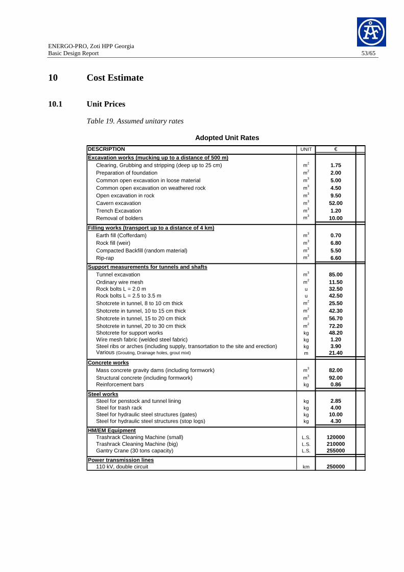
ENERGO-PRO, Zoti HPP Georgia Basic Design Report 53/65
10 Cost Estimate
10.1 Unit Prices
Table 19. Assumed unitary rates
UNIT €
Excavation works (mucking up to a distance of 500 m )Clearing, Grubbing and stripping (deep up to 25 cm) m2 1.75Preparation of foundation m2 2.00Common open excavation in loose material m3 5.00Common open excavation on weathered rock m3 4.50Open excavation in rock m3 9.50Cavern excavation m3 52.00Trench Excavation m3 1.20Removal of bolders m3 10.00
Filling works (transport up to a distance of 4 km)Earth fill (Cofferdam) m3 0.70Rock fill (weir) m3 6.80Compacted Backfill (random material) m3 5.50Rip-rap m3 6.60
Support measurements for tunnels and shaftsTunnel excavation m3 85.00Ordinary wire mesh m2 11.50Rock bolts L = 2.0 m u 32.50Rock bolts L = 2.5 to 3.5 m u 42.50Shotcrete in tunnel, 8 to 10 cm thick m2 25.50Shotcrete in tunnel, 10 to 15 cm thick m2 42.30Shotcrete in tunnel, 15 to 20 cm thick m2 56.70Shotcrete in tunnel, 20 to 30 cm thick m2 72.20Shotcrete for support works kg 48.20Wire mesh fabric (welded steel fabric) kg 1.20Steel ribs or arches (including supply, transortation to the site and erection) kg 3.90Various (Grouting, Drainage holes, grout mixt) m 21.40
Concrete worksMass concrete gravity dams (including formwork) m3 82.00Structural concrete (including formwork) m3 92.00Reinforcement bars kg 0.86
Steel worksSteel for penstock and tunnel lining kg 2.85Steel for trash rack kg 4.00Steel for hydraulic steel structures (gates) kg 10.00Steel for hydraulic steel structures (stop logs) kg 4.30
HM/EM EquipmentTrashrack Cleaning Machine (small) L.S. 120000Trashrack Cleaning Machine (big) L.S. 210000Gantry Crane (30 tons capacity) L.S. 255000
Power transmission lines110 kV, double circuit km 250000
Adopted Unit Rates
DESCRIPTION

EN
ER
GO
-PR
O, Z
oti H
PP
Geo
rgia B
asic Design
Rep
ort
54
/65
10.2 E
xpected Investment C
osts
Ta
ble
20. S
um
ma
ry of th
e exp
ecte
d co
sts for Z
oti HP
P
Civil Hydromechanical Mechanical Eletrical TotalWorks Works Equipment Equipment
Part C Part H Part M Part E
1 CATCH. 1: DIVERSION KHINISTSKALI + DIVERSION TUNNEL + CHANNEL 5,944.5 12.0 10.0 5,966.5 2 CATCH. 2: DAM "ZOTI" H= 45m 6,945.0 103.1 50.0 7,098.1 3 INTAKE STRUCTURE 64.4 37.4 50.0 151.8 4 CATCH. 3: DIVERSION GUBAZEULI CREEK + DIVERSION TUNNEL 368.1 19.9 10.0 398.0 5 CATCH. 4: DIVERSION KVIRILA 1,041.2 32.2 10.0 1,083.3 6 HEADRACE TUNNEL 11,141.1 11,141.1 7 UPSTREAM SURGE SHAFT 578.9 578.9 8 PRESSURE SHAFT 1,019.1 1,914.5 2,933.6 9 UNDERGROUND POWERHOUSE AND OUTDOOR SWITCHYARD 3,694.2 27.9 6,069.6 11,818.6 21,610.4
10 TAILRACE CHANNEL 939.1 939.1
Intermediate Total: 31,735.7 2,146.9 6,069.6 11,948.6 51,900.8
a Site Installation and Camp (only on civil costs) 15.0% 4,760.4 4,760.4 b Contingencies for C&H parts 15.0% 4,760.4 322.0 5,082.4 c Contingencies for E&M parts 10.0% 607.0 1,194.9 1,801.8
A Total Construction and Equipment Costs 41,256.4 2,469.0 6,676.6 13,143.5 63,545.4 Rate with respect to total cost A 64.9% 3.9% 10.5% 20.7% 100.0%
B Reimbursement for Land Acquisition --- 980.0 C Reimbursement for Resettlement --- - D Accesses (roads, bridges, tunnels) --- 10,400.0 E Various Expenses 0.8% 508.4 F Investigations 1.0% 635.5 G Feasibility Study, Final Design and Tendering 2.0% 1,270.9 H Design, Supervision and Administration 7.0% 4,448.2 I Connection to the Electrical National Grid (16 km) --- 4,000.0
TOTAL INVESTMENT COSTS: 85,788
103 €
Expected Project Costs

ENERGO-PRO, Zoti HPP Georgia Basic Design Report 55/65
10.3 Annual Costs and Prime Rate Cost of Energy
Prime cost of Energy
HPP "Zoti"
Total Construction and Equipment Cost 103 € 63,545.40 Civil 103 € 41,256.40
Hydraulic Steel Structures 103 € 2,468.98
Mechanical 103 € 6,676.56
Electrical 103 € 13,143.46
Total Cost various 103 € 22,242.90
Total Investment Cost 103 € 85,788.30
Construction Time years 3.5Interest rate during Construction (DSI) 9.5%Interest Cost 18,337.25
Total Investment 10 3 € 104,125.55
Interest rate (DSI) 9.5%q 1.095
Financial Evaluation Period [years]Civil 50 48.1%Hydraulic Steel Structures 50 2.9%Mechanical 50 7.8%Electrical 50 15.3%Various and Interest during Construction 50 25.9%Weighted Average 50.0
Annual Depreciatoin and Interest Cost 9,998.87
Maintenance cost 242.62 Civil 103 € 0.3% 123.77
Hydraulic Steel Structures 103 € 0.8% 19.75
Mechanical 103 € 0.5% 33.38
Electrical 103 € 0.5% 65.72
Operation Cost 717.61
Personnel Cost 103 € 457.29 Management 1500 1 37.69
Engineers 1200 3 90.45 Professional 700 8 140.71
Manual 500 15 188.45
Charges 103 € 0.0% -
Administration and Insurance 103 € 0.25% 260.31
TOTAL ANNUAL COST 103 € 10,959.10
Energy Production 225.1
PRIME COST OF ENERGY €/MWh 48.7
In the above table it is considered that there is no tariff difference between Peak and Base Load energy. However, with the proposed Gubazeuli reservoir it is possible to generate peak energy considering 5 hours per day. Therefore the total Energy Production can be divided in peak energy (82.7 GWh) and base energy (142.4 GWh).
ENERGO-PRO, Zoti HPP Georgia Basic Design Report 56/65
11 Environmental aspects
The basic design of Zoti HPP was developed in respect of the ecological situation. In the study it was very important to have as less influence on the environment as possible. Therefore it has been possible to use the river Gubazeuli and its effluents for renewable energy without a major negative effect on the ecological system of the river.
The long tunnels of the hydro power plants do not interfere to the normal development of the area or with the landscape; contrarily it brings new access roads and a new economical activity.
Due to the relatively sparse population characteristic at the project area, matters like land acquisition and resettlement that normally represent an important topic in hydroelectric projects, are not a main issue.
12 Conclusions and recommendations
The total investment cost, including interest costs during construction, amounts to 101.1 millions of Euros for the proposed scheme. The annual costs are calculated to reach 10.7 millions of Euros.
The two vertical Pelton turbines have an installed capacity of 24 MW each. The average annual energy production of Zoti HPP is estimated to be 225.1 GWh and the energy rate results 47.3 Euros/MWh (uniform selling rate)
With the foreseen daily storage capacity at Gubazeuli reservoir, it is possible to divide the total energy production into peak and base energy. For example, when assuming that 5 hours peak energy are generated, the peak energy will correspond to 40% of the total produced energy. Likewise if 8 peak hours are considered, the peak energy will correspond to 55% of the total produced energy. However, such benefit can be only evaluated when a peak and a base selling tariff have been established in the country and if it is so, the project becomes economically more attractive.
Environmental effects do not represent a critical issue for Zoti HPP. Nonetheless, a project of this dimension causes changes within the affected area. Therefore, of primary concern should be the minimization of the negative impacts of the project to the local population, or further, even to ameliorate the current living conditions. It is a fact that the project will cause indirect benefits to the region, i.e. social and economical development.
The scheme has only one operation organ (spherical valve) which allows a simple plant operation and consequently a friendly maintenance.
For the next design steps the following tasks are recommended to carry out in order to elaborate the Detail design (concession design):
• Electrical market study
• More information about legal aspects
• Comprehensive hydrological study
ENERGO-PRO, Zoti HPP Georgia Basic Design Report 57/65
• Geological Study
• Survey (Topography)
13 Kvirila HPP – Quick assessment of economical fea sibility
13.1 General layout
To evaluate the economical attractiveness of an additional hydro power plant, situated upstream of the derivation structure of the Kvirila catchment area at elevation 1144.0 m a.s.l. (element of the presented Zoti HPP scheme – Chapters 1 to 12 of the present report) a rough assessment of its economical feasibility has been carried out. The possible scheme of such a plant with daily storage capacity is illustrated in (Figure 17) and consists of a reservoir, a headrace channel combined with the access road to the dam, a head pond, a penstock, an outdoor powerhouse, a switchyard and a short tailrace duct. Also a new transmission line with a length of 6 km to connect the plant to the electrical national grid has been taken into account. For the installed capacity the same parameters, as adopted for the Zoti HPP have been considered, i.e. the design discharge is that one which corresponds to an exceedence value of 18.1% on the duration curve and the required storage capacity is determined to produce peak energy at least during 5 hours a day over the whole year. Considering a hydraulic head of around 280 m and a design discharge of 3.15 m3/s the resulting installed capacity is around 8 MW and the average annual energy production amounts to 34.7 GWh.
The Kvirila HPP, as presented in this chapter, is connected to the main access road system of the Zoti HPP. In the case this project would be realized as stand alone; i.e. independently of the Zoti HPP, additional cost for accesses and grid connection would arise. In the case the Zoti HPP would be realized, the final connection of the water conveyance system of the Kvirila HPP with the Zoti one should be studied more in detail. Maybe a solution can be found to connect the two plants without losing any head, because in the presented assessment some 20 m of head are not harnessed.
In this chapter the principal findings of the quick assessment of the Kvirila HPP are presented.
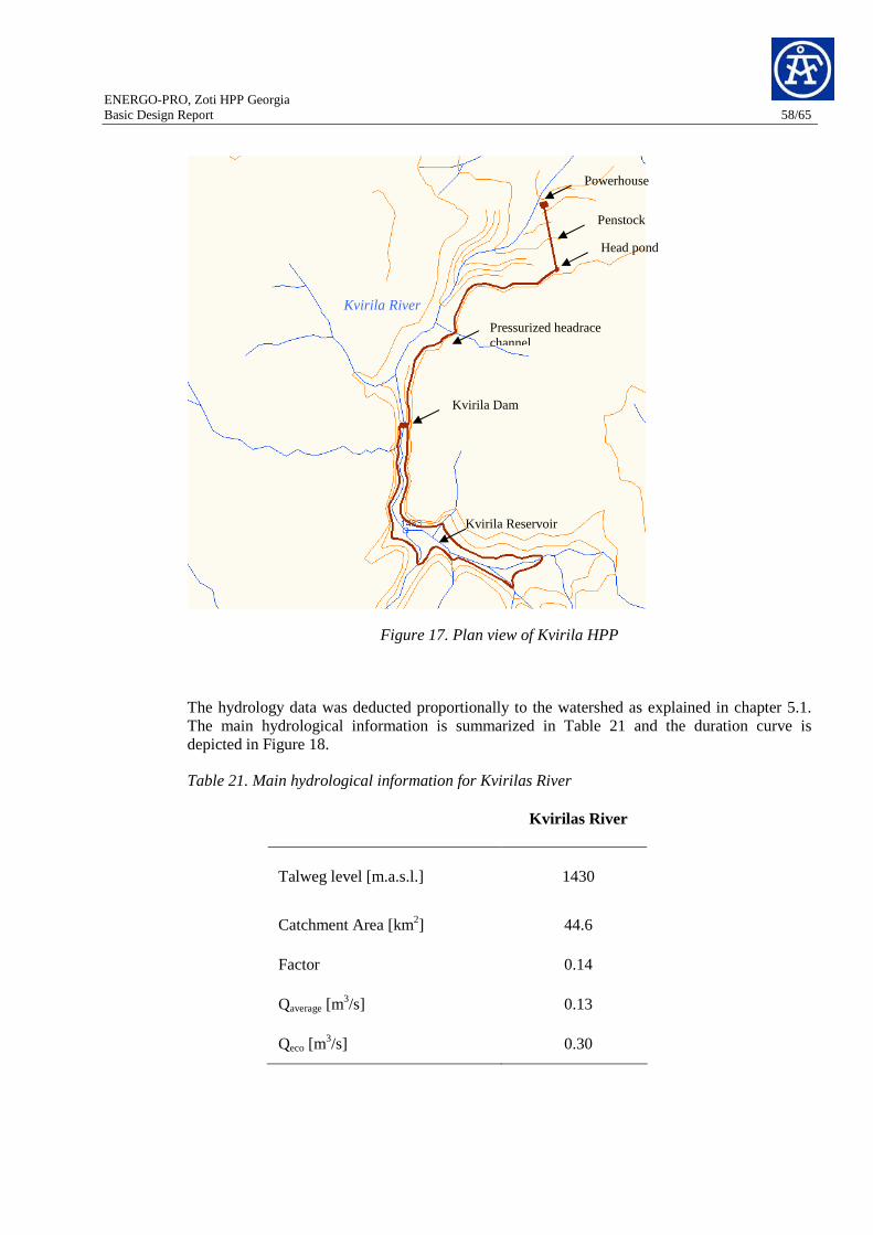
ENERGO-PRO, Zoti HPP Georgia Basic Design Report 58/65
Figure 17. Plan view of Kvirila HPP
The hydrology data was deducted proportionally to the watershed as explained in chapter 5.1. The main hydrological information is summarized in Table 21 and the duration curve is depicted in Figure 18.
Table 21. Main hydrological information for Kvirilas River
Kvirilas River
Talweg level [m.a.s.l.] 1430
Catchment Area [km2] 44.6
Factor 0.14
Qaverage [m3/s] 0.13
Qeco [m3/s] 0.30
Kvirila Dam
Kvirila River
Head pond
Pressurized headrace channel
Powerhouse
Kvirila Reservoir
Penstock

ENERGO-PRO, Zoti HPP Georgia Basic Design Report 59/65
0
1
2
3
4
5
6
7
8
0 5 10 15 20 25 30 35 40 45 50 55 60 65 70 75 80 85 90 95 100
Exceedence probability [%]
Dis
char
ge [m
3 /s]
Kvirila HPP
Design discharge = 3.15 m3/sExceedence probability = 18.1
Figure 18. Duration curve for Kvirila HPP
13.2 Salient features
A longitudinal profile indicationg the main elements of the scheme is shown in Figure 19 and Table 22 presents the main features for each of the Kvirila HPP’s components.
11501170119012101230125012701290131013301350137013901410143014501470
-100 0 100 200 300 400 500 600 700 800 900 1000 1100 1200 1300 1400 1500 1600
Distance to Kvirila Dam [m]
Ele
vatio
n [m
.a.s
.l.]
Head pond
Tailrace channel
PenstockL= 407 m
Outdoor Powerhouse
Max. op. Level = 1440 m.a.s.l.
Figure 19. Longitudinal profile Kvirila HPP
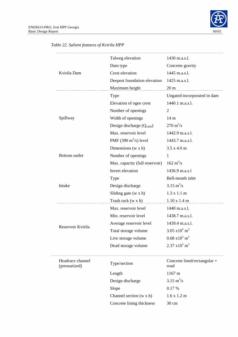
ENERGO-PRO, Zoti HPP Georgia Basic Design Report 60/65
Table 22. Salient features of Kvirila HPP
Talweg elevation 1430 m.a.s.l.
Dam type Concrete gravity
Crest elevation 1445 m.a.s.l.
Deepest foundation elevation 1425 m.a.s.l.
Kvirila Dam
Maximum height 20 m
Type Ungated-incorporated in dam
Elevation of ogee crest 1440.1 m.a.s.l.
Number of openings 2
Width of openings 14 m
Design discharge (Q1000) 270 m3/s
Max. reservoir level 1442.9 m.a.s.l.
Spillway
PMF (390 m3/s) level 1443.7 m.a.s.l.
Dimensions (w x h) 3.5 x 4.0 m
Number of openings 1 Bottom outlet
Max. capacity (full reservoir) 162 m3/s
Invert elevation 1436.9 m.a.s.l
Type Bell-mouth inlet
Design discharge 3.15 m3/s
Sliding gate (w x h) 1.3 x 1.1 m
Intake
Trash rack (w x h) 1.10 x 1.4 m
Max. reservoir level 1440 m.a.s.l.
Min. reservoir level 1438.7 m.a.s.l.
Average reservoir level 1439.4 m.a.s.l.
Total storage volume 3.05 x10⁵ m3
Live storage volume 0.68 x10⁵ m3
Reservoir Kvirila
Dead storage volume 2.37 x10⁵ m3
Type/section Concrete lined/rectangular + road
Length 1167 m
Design discharge 3.15 m3/s
Slope 0.17 %
Channel section (w x h) 1.6 x 1.2 m
Headrace channel (pressurized)
Concrete lining thickness 30 cm

ENERGO-PRO, Zoti HPP Georgia Basic Design Report 61/65
Flow velocity 1.64 m/s
Head losses 3.3 m
Road width 4.5
Start/end elevation 1436.9 m.a.s.l./1434.9 m.a.s.l.
Max. Operation level 1436.7 m.a.s.l.
Min. Operation level 1435.4 m.a.s.l.
Volume 2240 m3
Sliding gate 1.8 x 1.4 m3/s
Head Pond
Length 407 m
Internal diameter 1.60 m
Average thickness 0.80 cm
Flow velocity 1.60 m/s
Head losses 0.7
Penstock
Type Outdoor powerhouse
Turbines 1 x horizontal Francis
Turbine axes elevation 1162 m.a.s.l
Downstream water level 1160 m.a.s.l
Draft tube min. elevation 1158.4 m.a.s.l
Net head 1436 – 1160 = 276 m
Design discharge 3.15 m3/s
Installed capacity 8 MW
Machine efficiency 0.90
Powerhouse
Type Outdoor
Transformer type Three phases, Two Windings, oil filled
Capacity 9.5 MVA
Voltage ratio 110/8 kV
Total transformers provided 1
Transformer
Type Outdoor Open Air
Switchyard
Rated Voltage 110kV

ENERGO-PRO, Zoti HPP Georgia Basic Design Report 62/65
Total number of bays provided
1 + 1 in Zoti switchyard
Section Circular/ concrete lined
Length 30 m
Design discharge 3.15 m3/s
Internal diameter 1.60 m
Concrete lining thickness 25 cm
Flow velocity 1.60 m/s
Tailrace tunnel

EN
ER
GO
-PR
O, Z
oti H
PP
Geo
rgia B
asic Design
Rep
ort
63
/65
13.3 E
xpected Investment C
osts T
he expected investment costs presented in T
able 23 consider that Z
oti HP
P w
ill provide the access roads until K
virila intake. From
Kvrila inta
ke only 1.43 km of road are needed until
Kvrila D
am. C
ontrarily, assuming that any roads are
built in the area the amount of the item
D
will rise up to ~
3,4 millions of E
uros. Sim
ilarly, the connection of K
virila HP
P to the N
ational grid considers a 6 km
length 110kV
transmission line until Z
oti switchyard and a
fterwards it
will use the sam
e line as used per Zoti H
PP
for power evacuation.
Ta
ble
23. S
um
ma
ry of th
e exp
ecte
d co
sts for K
vrila
HP
P
HPP "Kvirila"
Civil Hydromechanical Mechanical Eletrical TotalWorks Works Equipment Equipment
Part C Part H Part M Part E
1 DAM "KVIRILA" H= 20 m 1,378.4 103.1 50.0 1,531.5 2 INTAKE STRUCTURE 21.0 19.5 50.0 90.5 3 HEADRACE CHANNEL + ACCESS ROAD 800.5 800.5 4 HEAD POND (vol= 2240 m3) 103.0 7.1 110.1 5 PENSTOCK 20.2 386.4 406.6 6 OUTDOOR POWERHOUSE 385.9 7.5 1,441.0 1,774.4 3,608.8 7 OUTDOOR SWITCHYARD 702.0 702.0 8 HEADRACE TUNNEL 25.6 25.6
Intermediate Total: 2,734.6 523.6 1,441.0 2,576.4 7,275.6
a Site Installation and Camp (only on civil costs) 15.0% 410.2 410.2 b Contingencies for C&H parts 15.0% 410.2 78.5 488.7 c Contingencies for E&M parts 10.0% 144.1 257.6 401.7
A Total Construction and Equipment Costs 3,555.0 602.1 1,585.1 2,834.0 8,576.3 Rate with respect to total cost A 41.5% 7.0% 18.5% 33.0% 100.0%
B Reimbursement for Land Acquisition --- 1.3 C Reimbursement for Resettlement --- - D Accesses (roads, bridges, tunnels) --- 400.0 E Various Expenses 0.8% 68.6 F Investigations 1.0% 85.8 G Feasibility Study, Final Design and Tendering 2.0% 171.5 H Design, Supervision and Administration 7.0% 600.3 I Connection to the Electrical National Grid (6 km) --- 1,500.0
TOTAL INVESTMENT COSTS: 11,404
103 €
Expected Project Costs

ENERGO-PRO, Zoti HPP Georgia Basic Design Report 64/65
13.4 Annual Costs and Prime Rate Cost of Energy
Prime cost of Energy
HPP "Kvirila"
Total Construction and Equipment Cost 103 € 8,576.30 Civil 103 € 3,555.03
Hydraulic Steel Structures 103 € 602.13
Mechanical 103 € 1,585.10
Electrical 103 € 2,834.04
Total Cost various 103 € 2,827.51
Total Investment Cost 103 € 11,403.81
Construction Time years 2.0Interest rate during Construction (DSI) 9.5%Interest Cost 1,625.04
Total Investment 103 € 13,028.85
Interest rate (DSI) 9.5%q 1.095
Financial Evaluation Period [years]Civil 50 31.2%Hydraulic Steel Structures 50 5.3%Mechanical 50 13.9%Electrical 50 24.9%Various and Interest during Construction 50 24.8%Weighted Average 50.0
Annual Depreciatoin and Interest Cost 1,251.11
Maintenance cost 37.58 Civil 103 € 0.3% 10.67
Hydraulic Steel Structures 103 € 0.8% 4.82
Mechanical 103 € 0.5% 7.93
Electrical 103 € 0.5% 14.17
Operation Cost 489.91 Personnel Cost 103 € 457.34
Management 1500 1 37.69 Engineers 1200 3 90.46
Professional 700 8 140.72 Manual 500 15 188.46
Charges 103 € 0.0% -
Administration and Insurance 103 € 0.25% 32.57
TOTAL ANNUAL COST 103 € 1,778.60
Energy Production 34.7
PRIME COST OF ENERGY €/MWh 51.3

ENERGO-PRO, Zoti HPP Georgia Basic Design Report 65/65
13.5 Conclusions
Kvirila HPP, combined with Zoti HPP presents a prime cost of energy of 51.3 Eur/MWh. Considering the whole cascade the weighted average results in 49.0 Eur/MWh, which means 0.62 % more of the Zoti HPP alone, but with an increased average annual energy production of 15% (225.1 + 34.7 = 259.8 GWh).
Baden, July 2009 – Anr, Arj, Drs, Smr, Vob AF-Colenco Ltd Hydropower Department
Markus Schmidmeister Technical responsible
Carina Andrade Project engineer
P:\1646_WK\Task2_Design\Reports\1646-03_Basic design report_Final_28.08.09.doc