Embed Size (px)
Citation preview

Pro
du
kte
D-H
G 4
00
Hochspannungs-Zündgerät
High Energy Spark IgnitorD-HG 400
� Ignition of liquid or gaseous fuelsin high-capacity industrial burners
� Compact design: control unit andignition lance as one modular unit
� Also available in explosion-proofversion with separate ignitionlance
� D-VE 500 Pneumatic RetractionUnit for automatic burner ignition
� no wear and tear because thyristorcontrolled
� Zünden von flüssigen odergasförmigen Brennstoffen fürIndustriebrenner großerLeistungen
� Kompaktbauform: Steuergerätund Zündlanze bilden eineBaueinheit
� In explosionsgeschützter Aus-führung mit getrennter Zünd-lanze lieferbar
� Vorschubeinrichtung D-VE 500 zur Automatisierungder Zündung
� kein Verschleiß da thyristor-gesteuert

Hochenergie-Zündgerät D-HG 400
� Anwendung
Das DURAG-Hochenergie-Zündgerät zündet Öl- und Gasbren-ner beliebiger Leistungen. In der Standardausführung sind dieZündlanze und das Steuergerät zu einer kompakten Einheit zusam-mengefasst.
Abhängig von der Ausführung des Zündgerätes lässt sich dieZündung über einen Drucktaster am Gerät oder automatisch durchAnlegen der Betriebsspannung auslösen.
Nach dem Zünden muss die Zündspitze zum Schutz vor thermi-scher Überlastung aus dem Flammenbereich gezogen werden. Dieskann im Handbetrieb oder im Automatikbetrieb durch eine DURAGVorschubeinrichtung D-VE 500 erfolgen. Bei speziellen Brennerkon-struktionen (z.B. Fackelanlagen) kann auf ein Zurückziehen verzich-tet werden, wenn die Flamme nach dem Zünden so weit abwandert,dass die thermische Belastung innerhalb der zulässigen Betriebs-temperatur bleibt.
Die Zündlanzenlänge wird nach den Erfordernissen der Anlagegefertigt.
� Funktion
Im Zündgerät wird in einem Hochspannungskondensator eineEnergie von 4,5 Ws eingespeichert. Mit einem verschleißfreienSchaltelement wird diese Energie über eine Bogenentladung (Fun-ke) an der Zündspitze freigesetzt. Diese Entladung zündet denBrennstoff.
Zur sicheren Zündung in der Startphase liefert das Gerät 60 slang 20 Zündfunken/s und schaltet dann auf 5 Zündfunken/szurück.
Es erfolgt eine Zündrückmeldung über die rote Leuchtdiodeoder den potentialfreien Kontaktausgang, wenn eine korrekte Entla-dung des Hochspannungskondensators festgestellt wurde.
� Anwendung D-VE 500
Das sichere Zünden eines Brenners mit dem D-HG 400 setzt einegenaue Positionierung der Zündspitze am Brennstoff-Luftgemisch,bzw. ins Brennstoff-Luftgemisch, voraus. Die Temperaturen im Be-
� Typen-Übersicht� D-HG 400-50: für Betrieb in automatischen Anlagen� D-HG 400-51: für Betrieb mit manueller Zündauslösung über
eingebaute Drucktaste� D-HG 400-53: Für den Betrieb in explosionsgefährdeten An-
lagen, gekapselt in einem Ex-Gehäuse nach Zündklasse EExde IIC T6, mit PTB-Zertifikat Nr. 94.C.1065
� D-HG 400-56: für Betrieb mit manueller Zündauslösung übereingebauten Rastenschalter
� D-HG 400-65: Anschluß der Zündlanze über Kabel� D-HG 400-72: Für den Betrieb in explosionsgefährdeten An-
lagen, gekapselt in einem Ex-Gehäuse nach Zündklasse EEx dIIC T6, mit INIEX Zertifikat Nr. 83.103.251.
� D-HG 400-73: Für den Betrieb in explosionsgefährdeten An-lagen, gekapselt in einem Ex-Gehäuse nach Zündklasse EEx dIIB T6, mit ISSeP-Zertifikat Nr. 95D.103.1222
� D-HG 400-80: Wie D-HG 400-51 als portables Zündgerät mitintegrierter Zündlanze, Handgriff und Start-Taster
� D-HG 400-81: Tragbares Batterie mit Schulterriemen und mitintegriertem Ladegerät, als Versorgung für das Zündgerät D-HG 400-80
� D-VE 500: Pneumatische Vorschubeinrichtung für Zündlanzen
reich der optimalen Zündzone sind jedoch in den meisten Fällenwährend der Betriebszeit des Brenners viel zu hoch, so daß es an derZündspitze zu Schäden führen würde.
Zur Automatisierung des Zündvorganges ist also eine Vorschu-beinrichtung einzusetzen. Sie übernimmt die Aufgabe, die Zünd-spitze genau in den Zündbereich des Brenners hineinzufahren undnach erfolgter Zündung wieder aus dem Flammenbereich heraus-zuziehen.
Die pneumatische Vorschubeinrichtung der Serie D-VE 500 istspeziell für diese Aufgabe entwickelt worden. Sie ist sehr robust auf-gebaut und läßt sich einfach und platzsparend an nahezu jedenBrenner montieren. Sie ist mit einem Hub von 300, 400, 500 und 600mm lieferbar (Standardtyp 300 mm Hub).
Die Vorschubeinrichtung ist mit einem Magnetventil ausgestat-tet, das durch Anlegen der Betriebsspannung die Umschaltung derVerfahrrichtung steuert. Der Kolben der Vorschubeinrichtung ist miteinem Permanentmagneten versehen, der mit den entsprechendenSchaltern eine oder beide Endlagen anzeigt.
Hochenergie-Zünd-gerät mit Zündlanze
High Energy SparkIgnitor with IgnitionLance

D-HG 400 High Energy Spark Ignitor
� Application
The DURAG High Energy Spark Ignitor ignites oil and gasburners of any capacity. In its standard version, the ignition lanceand the control unit form a compact module.
Depending on the ignition device model, ignition can betriggered either through a push button or automatically by feedingthe supply voltage.
After fuel ignition the igniter tip must be retracted from theflame area as a protection against heat overload. This can be donemanually or automatically, in the latter case by way of a DURAGD-VE 500 Pneumatic Retraction Unit. With special burner types (e.g.torch systems), no retraction is required if after ignition the flamewanders so far off that the thermal load stays within the permissibleworking temperature.
The length of the ignition lance is manufactured to suit thefurnace plant's requirements.
� Functional Description
Inside the ignition unit, the energy equivalent of 4.5 Ws is loadedinto a high-voltage capacitor. With the help of a wear proofswitching element, this energy is released to the ignition tip, wherethrough an arc discharge it is converted to heat. It is this arcdischarge that ignites the fuel.
For ensured ignition in the start-up phase the unit generates 20ignition sparks/s during 60 s and ensuingly reduces it to 5 ignitionsparks/s.
When the ignition device is switched to the supply voltage, theignition function message will be issued by way of the built-in LEDand through the ignition signal relay’s output contact.
� Application D-VE 500
The exact positioning of the ignition tip at the fuel-air mix iscrucial for the safe ignition of a burner with the D-HG 400. However,in most cases the temperature in the region of the optimal ignitionzone is much too high, so that damage would occur to the ignitiontip.
�� Unit Type Survey� D-HG 400-50: For use in automatic plants� D-HG 400-51: For use with manual ignition triggering
through an integrated push button� D-HG 400-53: For use in hazardous areas, with flameproof
enclosure executed as EEx de IIC T6, with PTB-Certificate No.94.C.1065
� D-HG 400-56: For use with manual ignition triggeringthrough built-in switch
� D-HG 400-65: Ignition lance connected by cable� D-HG 400-72: For use in hazardous areas, with flameproof
enclosure executed as EEx d IIC T6, with INIEX-Certificate No.83.103.251.
� D-HG 400-73: For use in hazardous areas, with flameproofenclosure executed as EEx d IIB T6, with ISSeP- Certificate No.95D.103.1222
� D-HG 400-80: Same as D-HG 400-51, but executed as porta-ble ignitor with integrated ignition lance and push button for"START".
� D-HG 400-81: Portable battery pack with shoulder strap andintegrated battery charger, to supply the D-HG 400-80 ignitor
� D-VE 500: Pneumatic retraction unit for ignition lances
A pneumatic retraction unit is employed which automates theignition process. This unit ensures that the ignition tip is insertedexactly into the ignition zone of the burner and after successfulignition, retracted from the flame area.
The pneumatic retraction unit D-VE 500 has been speciallydeveloped for this purpose. It has a robust construction and is easilymounted onto almost any burner. Delivery is available with a strokelength of 300, 400, 500 and 600 mm (The standard version is 300 mmstroke length).
The retraction unit is fitted with a solenoid valve which controlsthe switching of the direction of movement. The valve is activated bythe operating current. The piston of the retraction unit is fitted witha permanent magnet which shows one or both end limits withrespective switching.
Anwendungsbeispiel:Claus-Anlage
Claus Plant ApplicationExample
D-H
G 4
00
www.durag.de 10/00 - All specifications subject to change without notice
DURAG Industrie Elektronik GmbH & Co KG
Kollaustr. 105D-22453 Hamburg, Germany
Tel. +49 40 55 42 18-0Fax +49 40 58 41 54
Georg Hegwein GmbH & Co. KGAm Boschwerk 7
D-70469 Stuttgart, GermanyTel. +49 711 13 57 88-0Fax+49 711 13 57 88-5
VEREWA Umwelt- und Prozeßmeßtechnik GmbH
Kollaustr. 105D-22453 Hamburg, Germany
Tel. +49 40 55 42 18-0Fax +49 40 58 41 54
ORFEUS Combustion Engineering GmbH
An der Pönt 53aD-40885 Ratingen, Germany
Tel. +49 2102 9974-0Fax +49 2102 9974-41
DURAG, Inc.1970 Christensen Ave.West St. Paul, MN 55118
USATel. +1 651 451-1710Fax +1 651 457-7684
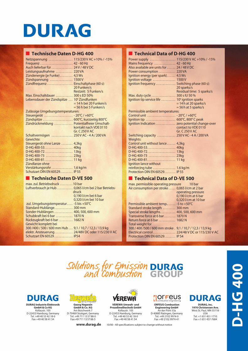
�� Technische Daten D-HG 400Netzspannung . . . . . . . . . . . . . . . . . 115/230 V AC +10% / -15%Frequenz . . . . . . . . . . . . . . . . . . . . . . . 42 - 60 HzAuch lieferbar für . . . . . . . . . . . . . . . 24 V / 48 V DCLeistungsaufnahme . . . . . . . . . . . . 220 VAZündenergie (je Funke) . . . . . . . . . 4,5 WsZündspannung . . . . . . . . . . . . . . . . 1500 VZündfrequenz . . . . . . . . . . . . . . . . . . Einschaltphase (60 s):
20 Funken/sRestzeit: 5 Funken/s
Max. Einschaltdauer . . . . . . . . . . . . 300 s ED 50%Lebensdauer der Zündspitze . . . 106 Zündfunken
= 14 h bei 20 Funken/s= 56 h bei 5 Funken/s
Zulässige Umgebungstemperaturen:Steuergerät . . . . . . . . . . . . . . . . . . . . - 20°C / +60°CZündspitze . . . . . . . . . . . . . . . . . . . . . 600°C, kurzzeitig 800°CZündrückmeldung . . . . . . . . . . . . . Potentialfreier Umschalt-
kontakt nach VDE 0110Gr. C 250 V AC
Schaltvermögen . . . . . . . . . . . . . . . 250 V AC - 4 A / 200 VAGewichte:Steuergerät ohne Lanze . . . . . . . . 4,3kgD-HG 400-53. . . . . . . . . . . . . . . . . . . . 40kgD-HG 400-72. . . . . . . . . . . . . . . . . . . . 13kgD-HG 400-73 . . . . . . . . . . . . . . . . . . . 23kgD-HG 400-81. . . . . . . . . . . . . . . . . . . . 11 kgZündlanze ohneVerstärkungsrohr . . . . . . . . . . . . . . . 1,6 kg/mSchutzart DIN EN 60529. . . . . . . . . IP 55
�� Technische Daten D-VE 500max. zul. Betriebsdruck . . . . . . . . . 10 barLuftverbrauch je Hub . . . . . . . . . . . 0,065 I/cm bei 2 bar Betriebs-
druck0,190 l/cm bei 6 bar0,320 I/cm bei 10 bar
zul. Umgebungstemperatur . . . . -5 bis +50°CStandard-Hublänge. . . . . . . . . . . . . 300 mmSonder-Hublängen . . . . . . . . . . . . . 400, 500, 600 mmSchubkraft bei 6 bar . . . . . . . . . . . . 1870 NRückzugkraft bei 6 bar . . . . . . . . . . 1682 NGewicht komplett bei 300 /400 / 500 / 600 mm Hub . . . 9,1 / 10,7 / 12,3 / 13,9 kgelektr. Ansteuerung. . . . . . . . . . . . . 24/48V DC oder 115/230 V ACSchutzart EN 60529 . . . . . . . . . . . . . IP54
�� Technical Data of D-HG 400Power supply . . . . . . . . . . . . . . . . . . 115/230 V AC +10% / -15%Mains frequency . . . . . . . . . . . . . . . 42 - 60 HzAlso available are units for . . . . . . 24 / 48 V DCPower consumption . . . . . . . . . . . . 220 VAIgnition energy (per spark) . . . . . . 4.5 WsIgnition voltage . . . . . . . . . . . . . . . . 1500 VIgnition frequency . . . . . . . . . . . . . . Switching phase (60 s):
20 sparks/sResidual time: 5 sparks/s
Max. duty cycle . . . . . . . . . . . . . . . . . 300 s IU 50 %Ignition tip service life . . . . . . . . . . 106 ignition sparks
= 14 h at 20 sparks/s= 56 h at 5 sparks/s
Permissible ambient temperatures:Control unit . . . . . . . . . . . . . . . . . . . . - 20°C / +60°CIgnition tip . . . . . . . . . . . . . . . . . . . . . 600°C, 800° C peakIgnition Indication . . . . . . . . . . . . . . zero potential change-over
contact to VDE 0110Gr. C 250 V AC
Switching capacity . . . . . . . . . . . . . 250 V AC - 4 A / 200 VAWeights:Control unit without lance . . . . . . 4,3kgD-HG 400-53. . . . . . . . . . . . . . . . . . . . 40kgD-HG 400-72. . . . . . . . . . . . . . . . . . . . 13kgD-HG 400-73 . . . . . . . . . . . . . . . . . . . 23kgD-HG 400-81. . . . . . . . . . . . . . . . . . . . 11 kgIgnition lance without reinforcing tube . . . . . . . . . . . . . . . . 1.6 kg/mProtection DIN EN 60529. . . . . . . . IP 55
�� Technical Data of D-VE 500max. permissible operating pressure 10 barAir consumption per stroke . . . . . 0,065 l/cm at 2 bar
operating pressure0,190 l/cm at 6 bar0,320 l/cm at 10 bar
Permissible ambient temp.. . . . . . -5 to +50°CStandard stroke length . . . . . . . . . 300 mmSpecial stroke lengths. . . . . . . . . . . 400, 500, 600 mmTransverse force at 6 bar . . . . . . . . 1870 NReturn force at 6 bar . . . . . . . . . . . . 1682 NTotal weight for 300 / 400 /500 / 600 mm stroke . 9,1 / 10,7 / 12,3 / 13,9 kgElectrical control . . . . . . . . . . . . . . . . 224/48 V DC or 115/230 V ACProtection DIN EN 60529. . . . . . . . IP 54