Embed Size (px)
Citation preview

ZION STATION RESTORATION PROJECT FINAL STATUS SURVEY RELEASE RECORD
UNIT 1 STEAM TUNNEL
EMBEDDED FLOOR DRAIN PIPE SURVEY UNIT 06209

FSS RELEASE RECORD UNIT 1 STEAM TUNNEL FLOOR DRAIN PIPE SURVEY UNIT 06209
[2]
PREPARED BY / DATE: J. Graham Radiological Engineer REVIEWED BY / DATE:
P. Giza
Radiological Engineer APPROVED BY / DATE:
D. Wojtkowiak
C/LT Manager
1/9/2019
1/9/2019
1/9/2019

FSS RELEASE RECORD UNIT 1 STEAM TUNNEL FLOOR DRAIN PIPE SURVEY UNIT 06209
[3]
TABLE OF CONTENTS
1. EXECUTIVE SUMMARY ................................................................................................... 5
2. SURVEY UNIT DESCRIPTION ......................................................................................... 5
3. CLASSIFICATION BASIS .................................................................................................. 5
4. DATA QUALITY OBJECTIVES (DQO) ........................................................................... 6
5. SURVEY DESIGN ................................................................................................................ 8
6. SURVEY IMPLEMENTATION........................................................................................ 14
7. SURVEY RESULTS............................................................................................................ 15
8. QUALITY CONTROL ....................................................................................................... 16
9. INVESTIGATIONS AND RESULTS ............................................................................... 16
10. REMEDIATION AND RESULTS ..................................................................................... 16
11. CHANGES FROM THE SURVEY PLAN ....................................................................... 17
12. DATA QUALITY ASSESSMENT (DQA) ........................................................................ 17
13. ANOMALIES....................................................................................................................... 17
14. CONCLUSION .................................................................................................................... 17
15. REFERENCES .................................................................................................................... 18
16. ATTACHMENTS ................................................................................................................ 18
ATTACHMENT 1 - FIGURES .......................................................................................... 19 ATTACHMENT 2 - SAMPLE DATA ............................................................................... 21 ATTACHMENT 3 - SIGN TEST ....................................................................................... 25 ATTACHMENT 4 - QC SAMPLE ASSESSMENT ......................................................... 28 ATTACHMENT 5 – GRAPHICAL PRESENTATIONS ................................................ 30

FSS RELEASE RECORD UNIT 1 STEAM TUNNEL FLOOR DRAIN PIPE SURVEY UNIT 06209
[4]
LIST OF TABLES
Table 1 - Dose Significant Radionuclides and Mixture ............................................................................ 7 Table 2 - Modified Base Case and Operational DCGLs .......................................................................... 8 Table 3 - Surrogate Ratios ........................................................................................................................ 9 Table 4 - Surrogate Base Case and Operational DCGLs ........................................................................ 10 Table 5 - Typical FSS Instrument Detection Sensitivities ...................................................................... 12 Table 6 - Synopsis of Survey Design ..................................................................................................... 13 Table 7 - Survey Data Collected ............................................................................................................. 14 Table 8 - Instrument and detector ........................................................................................................... 15 Table 9 - Unit 1 Steam Tunnel Floor Drains – Statistical Summary ...................................................... 16

FSS RELEASE RECORD UNIT 1 STEAM TUNNEL FLOOR DRAIN PIPE SURVEY UNIT 06209
[5]
1. EXECUTIVE SUMMARY
This Final Status Survey (FSS) Release Record for Survey Unit #S3-06209AF, the Unit 1 Steam Tunnel Embedded Floor Drain Pipe, has been generated for the Zion Station Restoration Project (ZSRP). The release record was developed in accordance with ZionSolutions procedure ZS-LT-300-001-005, “Final Status Survey Data Reporting” (Reference 1) and satisfies the requirements of Section 5.11 of the “Zion Station Restoration Project License Termination Plan” (LTP) (Reference 2).
FSS Sample Plan S3-06209AF was developed in accordance with ZionSolutions procedure ZS-LT-300-001-001, “Final Status Survey Package Development” (Reference 3) the ZSRP LTP, and guidance from NUREG-1575, Revision 1, “Multi-Agency Radiation Survey and Site Investigation Manual” (MARSSIM) (Reference 4).
FSS was conducted to demonstrate that the concentrations of residual radioactivity are equal to or below site-specific Derived Concentration Guideline Levels (DCGL) corresponding to the dose criterion in 10 CFR 20.1402. The Unit 1 Steam Tunnel Floor Drain piping was classified as MARSSIM Class 3.
The Steam Tunnel drain pipe was surveyed with a Ludlum 2350-1 Data Logger paired with a 44-159 gamma detector. Following excavation of the southeast corner of the Steam Tunnel, the drain piping was accessed through cleanout M5. The detector was able to access 132 feet of the pipe from this access point. Readings were taken at 2-foot intervals to allow enough readings to provide for the 10% coverage requirement for a Class 3 survey unit. The total length of this piping system was 479 linear feet.
For the FSS of the Unit 1 Steam Tunnel floor drain pipe, 68 readings were obtained. All of the readings were below a Sum-of-Fraction (SOF) of 0.5 when compared against the Operational DCGL for embedded pipe (OpDCGLEP) with the mean OpSOF reading of 0.00689. The mean SOF, when compared to the Base Case DCGL for embedded pipe (BcDCGLEP) was 0.0021, which results in the dose calculated for this survey unit of 0.0199 mrem/yr.
2. SURVEY UNIT DESCRIPTION
The Unit 1 Steam Tunnel drain piping consists of a 4-inch diameter pipe that is 479 linear feet in length. The floor of the tunnel is at 568 ft. elevation, with the drain piping embedded in the concrete approximately 2 feet deep.
3. CLASSIFICATION BASIS
Survey Unit #S3-06209AF was classified in accordance with ZionSolutions procedure ZS-LT-300-001-002, “Survey Unit Classification” (Reference 5).
The Turbine Building was initially classified as a Class 2 structure by the “Zion Station Historical Site Assessment” (Reference 6). LTP Section 5.5.2.1.2 changed the classification of

FSS RELEASE RECORD UNIT 1 STEAM TUNNEL FLOOR DRAIN PIPE SURVEY UNIT 06209
[6]
the Turbine Building basement from Class 2 to Class 3. The LTP states “The FSS units for the basements of the Turbine Building, the Crib House/Forebay, WWTF and the Circulating Water Discharge Tunnels are designated as Class 3 as defined in MARSSIM, section 2.2 in that the FSS units are expected to contain levels of residual activity at a small fraction of the DCGLs, based on site operating history and previous radiation surveys.”
4. DATA QUALITY OBJECTIVES (DQO)
Final Status Survey planning and design hinges on coherence with the Data Quality Objective (DQO) process to ensure, through compliance with explicitly defined inputs and boundaries, that the primary objective of the survey is satisfied. The DQO process is described in the ZSRP LTP in accordance with MARSSIM. The appropriate design for a given survey will be developed using the DQO process as outlined in Appendix D of MARSSIM.
The DQO process incorporated hypothesis testing and probabilistic sampling distributions to control decision errors during data analysis. Hypothesis testing is a process based on the scientific method that compares a baseline condition to an alternate condition. The baseline condition is technically known as the null hypothesis. Hypothesis testing rests on the premise that the null hypothesis is true and that sufficient evidence must be provided for rejection. In designing the survey plan, the underlying assumption, or null hypothesis was that residual activity in the survey unit exceeded the release criteria. Rejection of the null hypothesis would indicate that residual activity within the survey unit does not exceed the release criteria. Therefore, the survey unit would satisfy the primary objective of the FSS sample plan.
The primary objective of the FSS sample plan is to demonstrate that the level of residual radioactivity in Survey Unit #S3-06209AF did not exceed the release criteria specified in the LTP and that the potential dose from residual radioactivity is As Low As Reasonably Achievable (ALARA).
LTP Chapter 6, section 6.5.2 discusses the process used to derive the Radionuclides-of-Concern (ROC) for the decommissioning of ZNPS, including the elimination of insignificant dose contributors (IC) from the initial suite. Based upon the analysis of the mixture, it was determined that Co-60, Ni-63, Sr-90, Cs-134 and Cs-137 accounted for 99.5% of all dose in the non-activated contaminated concrete mixes.
The residual radioactivity in embedded piping located below the 588 foot grade that will remain and be subjected to FSS is discussed in LTP Chapter 2, section 2.3.3.7 and TSD 14-016, “Description of Embedded Piping, Penetrations, and Buried Pipe to Remain in Zion End State” (Reference 7). The DCGLs for embedded piping are listed in LTP Chapter 5, sections 5.2.7 and 5.2.8.
Due to absence of significant source term in the Turbine Building, the suite of ROC and radionuclide mixture derived for the Auxiliary Building concrete was considered as a

FSS RELEASE RECORD UNIT 1 STEAM TUNNEL FLOOR DRAIN PIPE SURVEY UNIT 06209
[7]
reasonable conservative mixture to apply to the Unit 1 Steam Tunnel embedded pipe for FSS planning and implementation. Table 1 reproduces the ROC from LTP Chapter 5, Table 5-2.
Table 1 - Dose Significant Radionuclides and Mixture
Radionuclide Auxiliary Building
% of Total Activity (normalized)(1)
Co-60 0.92%
Ni-63 23.71%
Sr-90 0.05%
Cs-134 0.01%
Cs-137 75.32% (1) Based on maximum percent of total activity from Table 20 of TSD 14-
019, normalized to one for the dose significant radionuclides.
A FSS is conducted on the interior surfaces of embedded piping to demonstrate that the concentrations of residual activity are equal to or below DCGLs corresponding to the dose criterion in 10CFR20.1402 (DCGLEP). DCGLEP were calculated for each of the remaining embedded pipe systems. The DCGLEP values for the Steam Tunnel Drain embedded pipe system from LTP Chapter 6, section 6.13 are referred to as Base Case DCGLs.
At ZNPS, compliance is demonstrated through the summation of dose from four distinct source terms for the end-state (basements, soils, buried pipe and groundwater). Each radionuclide-specific Base Case DCGL is equivalent to the level of residual radioactivity (above background levels) that could, when considered independently, result in a Total Effective Dose Equivalent (TEDE) of 25 mrem per year to an Average Member of the Critical Group (AMCG). To ensure that the summation of dose from each source term is 25 mrem/year or less after all FSS is completed, the Base Case DCGLs are reduced based on an expected, or a priori, fraction of the 25 mrem/year dose limit from each source term. The reduced DCGLs, or “Operational” DCGLs can be related to the Base Case DCGLs as an expected fraction of dose based on an a priori assessment of what the expected dose should be based on the results of site characterization, process knowledge and the extent of planned remediation. The Operational DCGL is then used as the DCGL for the FSS design of the survey unit (calculation of surrogate DCGLs, investigations levels, etc.). Details of the Operational DCGLs derived for each dose component and the basis for the applied a priori dose fractions are provided in ZionSolutions TSD 17-004, “Operational Derived Concentration Guideline Levels for Final Status Survey” (Reference 8).

FSS RELEASE RECORD UNIT 1 STEAM TUNNEL FLOOR DRAIN PIPE SURVEY UNIT 06209
[8]
The Base Case and Operational DCGLs for the Steam Tunnel Drain embedded pipe are listed in Tables 5-11 and 5-12 of the LTP.
LTP Chapter 5, section 5.5.5 discusses the alternate drilling spoils resident farmer scenario. The dose for the Steam Tunnel Drains in this scenario is calculated to be 71.16 mrem/year using the maximum hypothetical activity that could be allowed to remain. As a conservative measure, the Base Case DCGLs were adjusted by a factor of 2.89 (71.16/25), which will reduce the hypothetical maximum dose to 25 mrem/year.
The Modified Base Case DCGLs and the Operational DCGLs are reproduced in the Table 2.
Table 2 - Modified Base Case and Operational DCGLs
Radionuclide Modified Base Case
Embedded Pipe DCGL pCi/m2 (1)
Operational Embedded Pipe DCGL
pCi/m2
Co-60 1.41E+10 1.63E+09
Cs-134 3.19E+09 3.69E+08
Cs-137 4.22E+09 4.88E+08
Ni-63 4.36E+11 5.04E+10
Sr-90 1.55E+08 1.79E+07 (1) Values represent Base Case DCGLs from Table 5-11 for the Steam Tunnel
reduced by a factor of 2.89.
5. SURVEY DESIGN
The level of effort associated with planning a survey is based on the complexity of the survey and nature of the hazards. Guidance for preparing FSS plans is provided in procedure ZS-LT-300-001-001 “Final Status Survey Package Development.”
During FSS, concentrations for Hard-to-Detect (HTD) ROC Ni-63 and Sr-90 are inferred using a surrogate approach. Cs-137 is the principle surrogate radionuclide for Sr-90 and Co-60 is the principle surrogate radionuclide for Ni-63. The mean, maximum and 95% Upper Confidence Level (UCL) of the surrogate ratios for concrete core samples taken in the Auxiliary Building basement were calculated in ZionSolutions TSD 14-019, “Radionuclides of Concern for Soil and Basement Fill Model Source Terms” (Reference 9) and are presented in Table 3. The maximum ratios will be used in the surrogate calculations during this FSS. Equations 2 through 5 show the results of the calculations. The results of the surrogate calculations are listed in Table 4.

FSS RELEASE RECORD UNIT 1 STEAM TUNNEL FLOOR DRAIN PIPE SURVEY UNIT 06209
[9]
Table 3 - Surrogate Ratios
Ratios Auxiliary Building Mean Max 95%UCL
Ni-63/Co-60 44.143 180.450 154.632
Sr-90/Cs-137 0.001 0.002 0.002
The equation for calculating a surrogate DCGL is as follows:
Equation 1 𝑆𝑆𝑆𝑆𝑆𝑆𝑆𝑆𝑆𝑆𝑆𝑆𝑆𝑆𝑆𝑆𝑆𝑆𝐷𝐷𝐷𝐷𝐷𝐷𝐷𝐷 =
1
�� 1𝐷𝐷𝐷𝐷𝐷𝐷𝐷𝐷𝑆𝑆𝑆𝑆𝑆𝑆
� + � 𝑅𝑅2𝐷𝐷𝐷𝐷𝐷𝐷𝐷𝐷2
� + � 𝑅𝑅3𝐷𝐷𝐷𝐷𝐷𝐷𝐷𝐷3
� + ⋯� 𝑅𝑅𝑛𝑛𝐷𝐷𝐷𝐷𝐷𝐷𝐷𝐷𝑛𝑛
��
Using the Base Case and Operational DCGLs presented in Table 2 and the maximum ratios from Table 3, the following surrogate calculations were performed:
Equation 2
(Cs-137 Surrogate Base Case DCGL) 𝑆𝑆𝑆𝑆𝑆𝑆𝑆𝑆𝑆𝑆𝑆𝑆𝑆𝑆𝑆𝑆𝑆𝑆𝐷𝐷𝐷𝐷𝐷𝐷𝐷𝐷 (𝐷𝐷𝐶𝐶−137) =
1
�� 14.22𝐸𝐸09(𝐷𝐷𝐶𝐶−137)
� + � 0.0021.55𝐸𝐸08(𝑆𝑆𝑆𝑆−90)
��= 4.00𝐸𝐸09 𝑝𝑝𝐷𝐷𝑝𝑝/𝑚𝑚2
Equation 3
(Cs-137 Surrogate Operational DCGL) 𝑆𝑆𝑆𝑆𝑆𝑆𝑆𝑆𝑆𝑆𝑆𝑆𝑆𝑆𝑆𝑆𝑆𝑆𝐷𝐷𝐷𝐷𝐷𝐷𝐷𝐷 (𝐷𝐷𝐶𝐶−137) =
1
�� 14.88𝐸𝐸08(𝐷𝐷𝐶𝐶−137)
� + � 0.0021.79𝐸𝐸07(𝑆𝑆𝑆𝑆−90)
��= 4.63𝐸𝐸08 𝑝𝑝𝐷𝐷𝑝𝑝/𝑚𝑚2
Equation 4
(Co-60 Surrogate Base Case DCGL) 𝑆𝑆𝑆𝑆𝑆𝑆𝑆𝑆𝑆𝑆𝑆𝑆𝑆𝑆𝑆𝑆𝑆𝑆𝐷𝐷𝐷𝐷𝐷𝐷𝐷𝐷 (𝐷𝐷𝐶𝐶−60) =
1
�� 11.41𝐸𝐸10(𝐷𝐷0−60)
� + � 180.454.36𝐸𝐸11(𝑁𝑁𝑁𝑁−63)
��= 2.06𝐸𝐸09 𝑝𝑝𝐷𝐷𝑝𝑝/𝑚𝑚2
Equation 5
(Co-60 Surrogate Operational DCGL) 𝑆𝑆𝑆𝑆𝑆𝑆𝑆𝑆𝑆𝑆𝑆𝑆𝑆𝑆𝑆𝑆𝑆𝑆𝐷𝐷𝐷𝐷𝐷𝐷𝐷𝐷 (𝐷𝐷𝐶𝐶−60) =
1
�� 11.63𝐸𝐸9(𝐷𝐷0−60)
� + � 180.455.04𝐸𝐸10(𝑁𝑁𝑁𝑁−63)
��= 2.38𝐸𝐸08 𝑝𝑝𝐷𝐷𝑝𝑝/𝑚𝑚2

FSS RELEASE RECORD UNIT 1 STEAM TUNNEL FLOOR DRAIN PIPE SURVEY UNIT 06209
[10]
Table 4 - Surrogate Base Case and Operational DCGLs
Radionuclide Base Case
Embedded Pipe DCGL pCi/m2
Operational Embedded Pipe DCGL
pCi/m2
Co-60 2.06E+09 2.38E+08
Cs-134 3.19E+09 3.69E+08
Cs-137 4.00E+09 4.63E+08
The survey design calculated a gross gamma Operational DCGL of 1.75E+08 pCi/m2. The Action Level used for the surveys for this survey unit was 50% of this value: 8.74E+07 pCi/m2. The equation for calculating Gross Activity is as follows:
Equation 6 𝐷𝐷𝑆𝑆𝑆𝑆𝐺𝐺𝐺𝐺 𝐴𝐴𝐴𝐴𝑆𝑆𝑝𝑝𝐴𝐴𝑝𝑝𝑆𝑆𝐴𝐴 𝐷𝐷𝐷𝐷𝐷𝐷𝐷𝐷 = 1
� f1DCGL1 + f2
DCGL2 + fNDCGLN�
The normalized gamma mixture was applied to the Operational DCGLs for the gamma emitting nuclides in Table 2 in the following equation:
Equation 7
(Gross Gamma Activity DCGL) 𝐷𝐷𝑆𝑆𝑆𝑆𝐺𝐺𝐺𝐺 𝐴𝐴𝐴𝐴𝑆𝑆𝑝𝑝𝐴𝐴𝑝𝑝𝑆𝑆𝐴𝐴 𝐷𝐷𝐷𝐷𝐷𝐷𝐷𝐷 = 1
�0.987804.88𝐸𝐸08 + 0.01207
1.63𝐸𝐸09 + 0.000133.69𝐸𝐸08�
= 4.92𝐸𝐸08 𝑝𝑝𝐷𝐷𝑝𝑝/𝑚𝑚2
The Gross Activity DCGL was then used in the surrogate equation using the surrogate ratios from Table 3:
Equation 8
(Surrogate Gross Gamma Activity DCGL) 𝑆𝑆𝑆𝑆𝑆𝑆𝑆𝑆𝑆𝑆𝑆𝑆𝑆𝑆𝑆𝑆𝑆𝑆𝐷𝐷𝐷𝐷𝐷𝐷𝐷𝐷 (𝑔𝑔𝑔𝑔𝑔𝑔𝑔𝑔𝑔𝑔) =
1
�� 14.92𝐸𝐸08� + � 180.45
5.04𝐸𝐸10(𝑁𝑁𝑁𝑁−63)� + � 0.002
1.79𝐸𝐸07(𝑆𝑆𝑆𝑆−90)��
= 1.75𝐸𝐸08 𝑝𝑝𝐷𝐷𝑝𝑝/𝑚𝑚2
The Unit 1 Steam Tunnel Floor drain system piping is Class 3 embedded pipe. For the survey of pipe internal surfaces, areal coverage is achieved by the “area of detection” for each static measurement taken. Scanning, in the traditional context, is not applicable to the survey of pipe internal surfaces. For the survey of these pipes, the pipe detector was calibrated for the specific geometry of the 4-inch pipes. For a 4-inch Internal Diameter (ID) pipe, each measurement has a calculated Field-of-View (FOV) of 1.05 ft2 (0.097 m2).
FSS RELEASE RECORD UNIT 1 STEAM TUNNEL FLOOR DRAIN PIPE SURVEY UNIT 06209
[11]
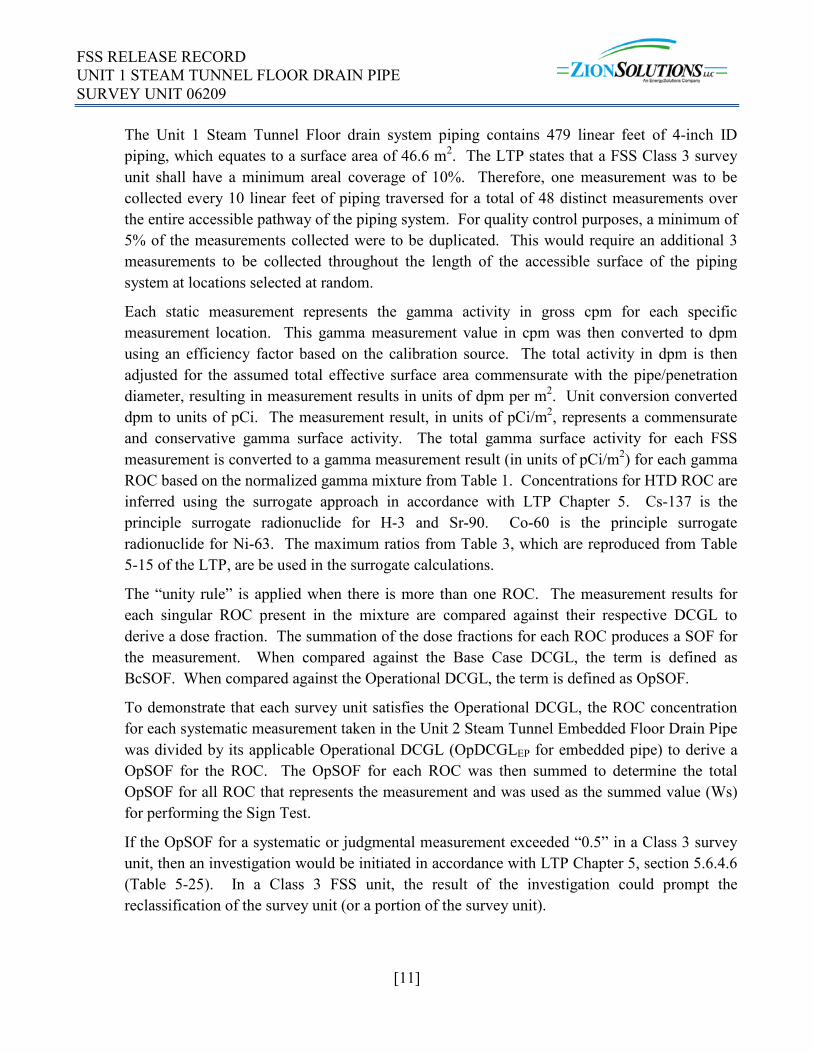
The Unit 1 Steam Tunnel Floor drain system piping contains 479 linear feet of 4-inch ID piping, which equates to a surface area of 46.6 m2. The LTP states that a FSS Class 3 survey unit shall have a minimum areal coverage of 10%. Therefore, one measurement was to be collected every 10 linear feet of piping traversed for a total of 48 distinct measurements over the entire accessible pathway of the piping system. For quality control purposes, a minimum of 5% of the measurements collected were to be duplicated. This would require an additional 3 measurements to be collected throughout the length of the accessible surface of the piping system at locations selected at random.
Each static measurement represents the gamma activity in gross cpm for each specific measurement location. This gamma measurement value in cpm was then converted to dpm using an efficiency factor based on the calibration source. The total activity in dpm is then adjusted for the assumed total effective surface area commensurate with the pipe/penetration diameter, resulting in measurement results in units of dpm per m2. Unit conversion converted dpm to units of pCi. The measurement result, in units of pCi/m2, represents a commensurate and conservative gamma surface activity. The total gamma surface activity for each FSS measurement is converted to a gamma measurement result (in units of pCi/m2) for each gamma ROC based on the normalized gamma mixture from Table 1. Concentrations for HTD ROC are inferred using the surrogate approach in accordance with LTP Chapter 5. Cs-137 is the principle surrogate radionuclide for H-3 and Sr-90. Co-60 is the principle surrogate radionuclide for Ni-63. The maximum ratios from Table 3, which are reproduced from Table 5-15 of the LTP, are be used in the surrogate calculations.
The “unity rule” is applied when there is more than one ROC. The measurement results for each singular ROC present in the mixture are compared against their respective DCGL to derive a dose fraction. The summation of the dose fractions for each ROC produces a SOF for the measurement. When compared against the Base Case DCGL, the term is defined as BcSOF. When compared against the Operational DCGL, the term is defined as OpSOF.
To demonstrate that each survey unit satisfies the Operational DCGL, the ROC concentration for each systematic measurement taken in the Unit 2 Steam Tunnel Embedded Floor Drain Pipe was divided by its applicable Operational DCGL (OpDCGLEP for embedded pipe) to derive a OpSOF for the ROC. The OpSOF for each ROC was then summed to determine the total OpSOF for all ROC that represents the measurement and was used as the summed value (Ws) for performing the Sign Test.
If the OpSOF for a systematic or judgmental measurement exceeded “0.5” in a Class 3 survey unit, then an investigation would be initiated in accordance with LTP Chapter 5, section 5.6.4.6 (Table 5-25). In a Class 3 FSS unit, the result of the investigation could prompt the reclassification of the survey unit (or a portion of the survey unit).

FSS RELEASE RECORD UNIT 1 STEAM TUNNEL FLOOR DRAIN PIPE SURVEY UNIT 06209
[12]
Embedded pipe survey units have a relatively small surface area leading to Operational DCGLs that are higher than the wall/floor Operational DCGLs. The reason for this fact is that the total internal surface area of the embedded pipe survey unit in a given basement is much less than the total wall/floor surface area of the basement containing them. To eliminate the potential for activity levels in embedded pipe that could lead to releases greater than surrounding walls and floors, the following remediation and grouting action levels were applied to measurements of surface activity in embedded pipe.
• If maximum activity exceeds the Base Case DCGLEP from Table 2 (SOF >1), then remediation was performed.
• If the maximum activity in an embedded pipe exceeded the surface Operational DCGLB from LTP Chapter 5, Table 5-4 (SOF>1) in the building that contains it, but was below the Base Case DCGLEP from Table 2, then the embedded pipe was remediated or grouted.
• If an embedded pipe was remediated and the maximum activity continues to exceed the surface Operational DCGLB from LTP Chapter 5, Table 5-4 (SOF>1), but is less than the Operational DCGLEP from Table 3, then the embedded pipe was grouted.
• If the maximum activity was below the surface Operational DCGLB from LTP Chapter 5, Table 5-4 (SOF>1), then grouting of the pipe was not required.
The instrumentation used for the FSS of the Unit 1 Steam Tunnel Drain embedded pipe was the Ludlum Model 2350-1 and the Model 44-159 detector. The instrumentation sensitivities are provided in Chapter 5 of the LTP and are reproduced in Table 5.
Table 5 - Typical FSS Instrument Detection Sensitivities
Instrument /Detector Radiation
BKGD count time
(min.)
Typical BKGD (cpm)
Typical Instrument Efficiencyab
Count Time (min.)
Static MDC
(dpm/100 cm2)
Scan MDC
(dpm/100 cm2)
Ludlum 2350-1/ 44-159 Gamma 1 700 0.024 1 5,250 N/A
a) Typical calibration source used is Cs-137. The efficiency is determined by counting the source with the detector in a fixed position from the source (reproducible geometry). The εt value is based on ISO-7503-1 and conditions noted for each detector.
b) The efficiency varies for the pipe detectors depending on the pipe diameter used. The efficiency used for the table is the average efficiency value for the pipe diameters. The detectors and diameters are: Model 44-159: 2-4 in. dia., Model 44-157: 4-8 in. dia., Model 44-162: 8-12 in. diameter.
In compliance with ZS-LT-01, “Quality Assurance Project Plan (QAPP) for Characterization and Final Status Survey” (Reference 10), replicate measurements were to be performed on 5% of the static measurement locations.
FSS RELEASE RECORD UNIT 1 STEAM TUNNEL FLOOR DRAIN PIPE SURVEY UNIT 06209
[13]
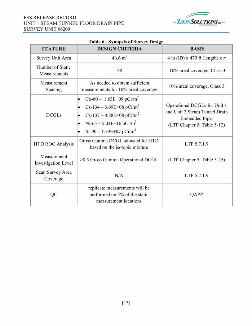
Table 6 - Synopsis of Survey Design FEATURE DESIGN CRITERIA BASIS
Survey Unit Area 46.6 m2 4 in (ID) x 479 ft (length) x π
Number of Static Measurements 48 10% areal coverage, Class 3
Measurement Spacing
As needed to obtain sufficient measurements for 10% areal coverage 10% areal coverage, Class 3
DCGLs
• Co-60 – 1.63E+09 pCi/m2 • Cs-134 – 3.69E+08 pCi/m2 • Cs-137 – 4.88E+08 pCi/m2 • Ni-63 – 5.04E+10 pCi/m2 • Sr-90 – 1.79E+07 pCi/m2
Operational DCGLs for Unit 1 and Unit 2 Steam Tunnel Drain
Embedded Pipe, (LTP Chapter 5, Table 5-12)
HTD ROC Analysis Gross Gamma DCGL adjusted for HTD based on the isotopic mixture LTP 5.7.1.9
Measurement Investigation Level >0.5 Gross Gamma Operational DCGL (LTP Chapter 5, Table 5-25)
Scan Survey Area Coverage
N/A LTP 5.7.1.9
QC replicate measurements will be performed on 5% of the static
measurement locations QAPP

FSS RELEASE RECORD UNIT 1 STEAM TUNNEL FLOOR DRAIN PIPE SURVEY UNIT 06209
[14]
6. SURVEY IMPLEMENTATION
Survey instructions for this FSS were incorporated into and performed in accordance with FSS Sample Plan #S3-06209AF, which was developed in accordance with ZionSolutions procedure ZS-LT-300-001-001, “Final Status Survey Package Development”. The FSS unit was inspected and controlled in accordance with ZionSolutions procedure ZS-LT-300-001-003, “Isolation and Control for Final Status Survey” (Reference 11).
The approach used for the radiological survey of the interior surfaces of the Steam Tunnel floor drain piping involved the insertion of a 1” x 1” CsI detector that was attached to the See Snake camera system and transported through the pipe to the maximum deployment length, or to a location of drain drop. A simple “push-pull” methodology was used, whereby the position of the detector in the piping system could be easily determined in a reproducible manner. Footage was tabulated on the See Snake, then measurements were obtained at 2 foot intervals while backing out of the pipe section.
A background value was also determined for the detector/instrument combination to be used prior to deployment. The background value was obtained at the location where the pre-use response check of the instrument was performed. The background value was primarily used to ensure that the detector had not become cross-contaminated by any previous use. Background was not subtracted from any measurement.
Daily prior to use and daily following use, each detector was subjected to an Operational Response Check in accordance with procedure ZS-LT-300-001-006, “Radiation Surveys of Pipe Interiors Using Sodium/Cesium Iodide Detectors” (Reference 12). The Daily Operational Response Check compared the background response and the response to check sources ranges established for normal background and detector source response to ensure that the detector was working properly.
Surveys of the Unit 1 Steam Tunnel floor drain piping were performed on May 1, 2018. The survey was completed in 1 day. The piping was accessed through the “Y” cleanout position (M5) located in the southeast corner of the Unit 1 Steam Tunnel. The See Snake and detector were inserted 132 feet into the pipe. Because the entire length of the pipe was not available for survey, it was decided to take measurements at 2 foot intervals to obtain sufficient readings to meet the 10% coverage required for the Class 3 survey unit. The Survey Design called for 48 readings to be taken at 10 foot intervals. Table 7 summarizes the data collected:
Table 7 - Survey Data Collected
Pipe run Length surveyed
# of measurements taken Comment
M5 132 68 4 QC readings taken

FSS RELEASE RECORD UNIT 1 STEAM TUNNEL FLOOR DRAIN PIPE SURVEY UNIT 06209
[15]
The instrument and detector used for this survey are presented in Table 8. The instrument and detector were verified to be properly calibrated prior to use.
Table 8 - Instrument and detector Instrument/Detector
Type Serial # Calibration Due Date
Ludlum 2350-1 304718 3/5/19
Ludlum 44-159 PR327895 3/14/19
Daily prior to use (Pre-Test) and daily upon completion of surveys (Post-Test), response checks were performed in accordance with procedure ZS-LT-300-001-006 for each detector and data logger pairing. In addition, all instruments and detectors were physically inspected for mechanical damage as part of the response check process. During the FSS, no instances were encountered where an instrument and/or detector failed a Pre or Post response check or were found to be physically damaged during the inspection.
7. SURVEY RESULTS
After completion of the FSS measurements in the pipe, the sample plan was reviewed to confirm the completeness of the survey and the survey data was validated in accordance with procedure ZS-LT-300-001-004, “Final Status Survey Data Assessment” (Reference 13). Data processing includes converting measurement data into reporting units, validating instrument applicability and sensitivity, calculating relevant statistical quantities, and verification that all DQO have been met. In accordance with the procedure, a preliminary Data Assessment was prepared.
The primary gamma emitting ROC for the FSS of the Unit 1 Steam Tunnel Floor Drains FSS unit are Co-60, Cs-134 and Cs-137. Ni-63 and Sr-90 are also ROC for the Unit 1 Steam Tunnel Floor Drains. Ni-63 is inferred from the measured concentration of Co-60, while Sr-90 is inferred from the measured concentration of Cs-137.
All measurements were less than 50% of the OpDCGL, meeting the requirement for a Class 3 area.
The mean of the OpSOF for all 68 samples was 0.0069.
The activity in this pipe must also be compared to the OpDCGLB for the building that contains it. According to Table 5-20 of the LTP, the Steam Tunnel drains are included with the Turbine Building. The results of this comparison show that 62 of the sample SOFs were greater than 1 when compared to the OpDCGLB for the Turbine Building, with a maximum SOF of 4.86, therefore grouting of this piping system is required.

FSS RELEASE RECORD UNIT 1 STEAM TUNNEL FLOOR DRAIN PIPE SURVEY UNIT 06209
[16]
The results of the data assessment for the embedded floor drain pipe are provided in Attachment 2. A statistical summary of the data is presented in Table 9.
The data collected passed the Sign Test. The result of the Sign Test is provided in Attachment 3.
Table 9 - Unit 1 Steam Tunnel Floor Drains – Statistical Summary
Radionuclide Mean Max Min Standard
Deviation Base Case DCGLEP Nuclide
Mean SOF (BcDCGLEP) (pCi/m2) (pCi/m2) (pCi/m2) (pCi/m2) (pCi/m2)
Co-60 3.80E+04 9.83E+04 8.36E+03 1.95E+04 1.41E+10 0.0000 Cs-134 4.13E+02 1.07E+03 9.09E+01 2.12E+02 3.19E+09 0.0000 Cs-137 3.11E+06 8.05E+06 6.85E+05 1.60E+06 4.22E+09 0.0007 Ni-63(1) 6.86E+06 1.77E+07 1.51E+06 3.52E+06 4.36E+11 0.0001 Sr-90(1) 6.23E+03 1.61E+04 1.37E+03 3.19E+03 1.55E+08 0.0001
(1) Concentrations for Ni-63 and Sr-90 are inferred Mean BcSOF 0.0008
Assigned Dose 0.0199
8. QUALITY CONTROL
In compliance with ZS-LT-01, replicate measurements were performed on 5% of the survey locations chosen at random. Four (4) replicate measurements were taken. Using the acceptance criteria specified ZS-LT-01, “Quality Assurance Project Plan (QAPP) for Characterization and Final Status Survey”, there was acceptable agreement between the replicate readings and the original readings. Refer to Attachment 4 for quality control analysis results.
9. INVESTIGATIONS AND RESULTS
As all measurements in the accessible pipe interior surface area was below a SOF of 0.5, no investigations were required or performed.
10. REMEDIATION AND RESULTS
No remediation was performed in this piping Survey Unit.

FSS RELEASE RECORD UNIT 1 STEAM TUNNEL FLOOR DRAIN PIPE SURVEY UNIT 06209
[17]
11. CHANGES FROM THE SURVEY PLAN
Only 132 feet of the piping was accessible for survey, therefore readings were taken at 2-foot intervals in the pipe run to obtain enough measurements to meet the 10% coverage requirement for Class 3 survey units.
The survey instructions called for a 44-157 detector to be used for the survey. Due to the size limitation for a 4-inch pipe, the smaller 44-159 detector was used instead.
12. DATA QUALITY ASSESSMENT (DQA)
In accordance with procedure ZS-LT-300-001-004, the DQOs, sample design, and data were reviewed for completeness, accuracy, and consistency. Documentation was complete and legible. The FSS unit was properly classified as Class 3. All measurement results were individually reviewed and validated. The number of measurements was sufficient to meet the requirement of 10% areal coverage of accessible surfaces. The instrumentation used to perform the FSS were in calibration, capable of detecting the activity with an adequate MDC and successfully response checked prior to and following use. An adequate number of replicate measurements were taken and the results meet the acceptance criteria as specified in the QAPP.
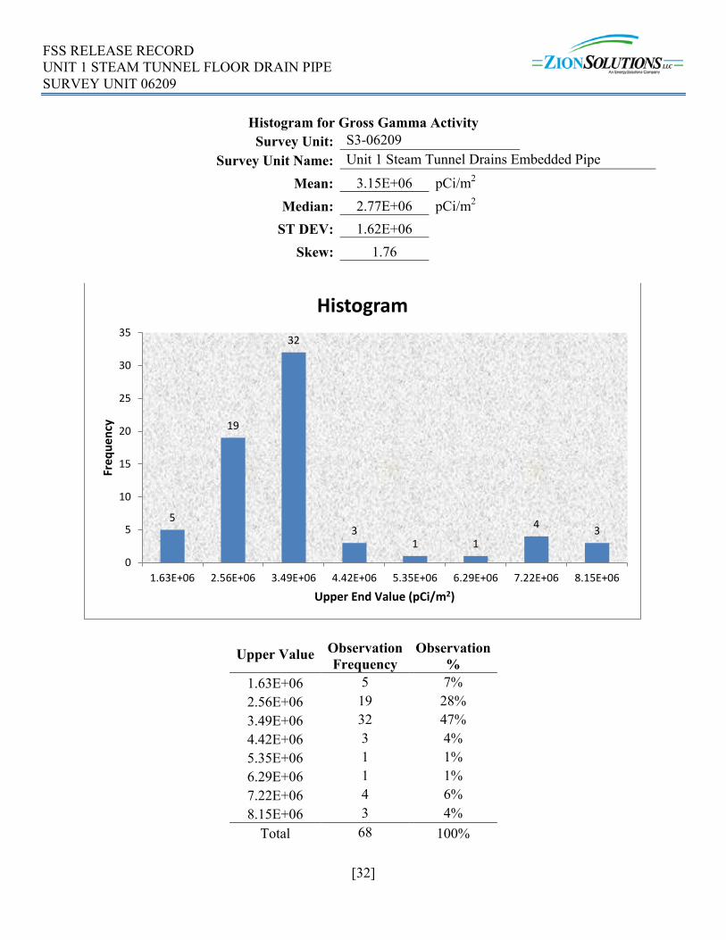
The data for Gross Gamma Activity is represented graphically through a frequency plot and a quantile plot. All graphical representations are provided in Attachment 5.
13. ANOMALIES
No anomalies were observed during the performance or analyses of the survey.
14. CONCLUSION
Sixty-eight (68) static measurements were taken in the Unit 1 Steam Tunnel Floor Drain piping, taken at 2-foot intervals. The accessible length of pipe was 132 feet, therefore the 10% areal survey coverage required for Class 3 survey units was met.
All of the measurements were below a SOF of 0.5, when compared to the OpDCGLEP. The average OpSOF for the survey unit is 0.0069. The requirements for a Class 3 survey unit have been met.
The Sign Test was passed, and the Null Hypothesis was rejected. A Retrospective Power Curve showed that adequate power was achieved.
The dose contribution from embedded pipe in Survey Unit #S3-06209AF, “Unit 1 Steam Tunnel Embedded Floor Drain Pipe”, is 0.0199 mrem/yr TEDE, based on the average concentration of the ROC in samples used for non-parametric statistical sampling.
Survey Unit #S3-06209AF, “Unit 1 Steam Tunnel Embedded Floor Drain Pipe” is acceptable for unrestricted release.

FSS RELEASE RECORD UNIT 1 STEAM TUNNEL FLOOR DRAIN PIPE SURVEY UNIT 06209
[18]
15. REFERENCES
1. ZionSolutions procedure ZS-LT-300-001-005, “Final Status Survey Data Reporting”
2. “Zion Station Restoration Project License Termination Plan” (LTP)
3. ZionSolutions procedure ZS-LT-300-001-001, “Final Status Survey Package Development”
4. NUREG-1575, Revision 1, “Multi-Agency Radiation Survey and Site Investigation Manual” (MARSSIM)
5. ZionSolutions procedure ZS-LT-300-001-002, “Survey Unit Classification”
6. “Zion Station Historical Site Assessment” (HSA)
7. ZionSolutions TSD 14-016, “Description of Embedded Piping, Penetrations, and Buried Pipe to Remain in Zion End State”
8. ZionSolutions TSD 17-004, “Operational Derived Concentration Guideline Levels for Final Status Survey”
9. ZionSolutions TSD 14-019, “Radionuclides of Concern for Soil and Basement Fill Model Source Terms”
10. ZionSolutions procedure ZS-LT-01, “Quality Assurance Project Plan (QAPP) for Characterization and Final Status Survey”
11. ZionSolutions procedure ZS-LT-300-001-003, “Isolation and Control for Final Status Survey”
12. ZionSolutions procedure ZS-LT-300-001-006, “Radiation Surveys of Pipe Interiors Using Sodium/Cesium Iodide Detectors”
13. ZionSolutions procedure ZS-LT-300-001-004, “Final Status Survey Data Assessment”
16. ATTACHMENTS
1. Attachment 1 – Figures
2. Attachment 2 – Sample Data
3. Attachment 3 – Sign Test
4. Attachment 4 – QC Sample Assessment
5. Attachment 5 – Graphical Presentations

ATTACHMENT 1 - FIGURES

FSS RELEASE RECORD UNIT 1 STEAM TUNNEL FLOOR DRAIN PIPE SURVEY UNIT 06209
[20]
FIGURE 1

FSS RELEASE RECORD UNIT 1 STEAM TUNNEL FLOOR DRAIN PIPE SURVEY UNIT 06209
[21]
ATTACHMENT 2 - SAMPLE DATA

FSS RELEASE RECORD UNIT 1 STEAM TUNNEL FLOOR DRAIN PIPE SURVEY UNIT 06209
[22]
Pipe Section Position
Gross Gamma Activity
Co-60 Conc.
Cs-134 Conc.
Cs-137 Conc.
Ni-63 Conc.
Sr-90 Conc. Co-60
SOF Cs-134
SOF Cs-137
SOF Ni-63 SOF
Sr-90 SOF SOF
(pCi/m2) (pCi/m2) (pCi/m2) (pCi/m2) (pCi/m2) (pCi/m2) N/A 136 3.42E+06 4.13E+04 4.49E+02 3.38E+06 7.45E+06 6.76E+03 2.53E-05 1.22E-06 6.93E-03 1.48E-04 3.78E-04 0.00748
134 2.41E+06 2.90E+04 3.16E+02 2.38E+06 5.24E+06 4.75E+03 1.78E-05 8.55E-07 4.87E-03 1.04E-04 2.66E-04 0.00526 132 1.83E+06 2.21E+04 2.40E+02 1.81E+06 3.98E+06 3.61E+03 1.35E-05 6.50E-07 3.70E-03 7.90E-05 2.02E-04 0.00400 130 2.52E+06 3.04E+04 3.30E+02 2.49E+06 5.49E+06 4.98E+03 1.87E-05 8.96E-07 5.10E-03 1.09E-04 2.78E-04 0.00551 128 2.97E+06 3.58E+04 3.89E+02 2.93E+06 6.46E+06 5.86E+03 2.20E-05 1.05E-06 6.01E-03 1.28E-04 3.28E-04 0.00649 126 2.28E+06 2.75E+04 2.99E+02 2.25E+06 4.96E+06 4.50E+03 1.69E-05 8.10E-07 4.61E-03 9.84E-05 2.51E-04 0.00498 124 3.72E+06 4.49E+04 4.88E+02 3.68E+06 8.11E+06 7.36E+03 2.76E-05 1.32E-06 7.54E-03 1.61E-04 4.11E-04 0.00814
122 1.47E+06 1.77E+04 1.93E+02 1.45E+06 3.20E+06 2.90E+03 1.09E-05 5.22E-07 2.97E-03 6.35E-05 1.62E-04 0.00321 120 1.37E+06 1.65E+04 1.79E+02 1.35E+06 2.98E+06 2.70E+03 1.01E-05 4.86E-07 2.77E-03 5.91E-05 1.51E-04 0.00299
118 1.70E+06 2.05E+04 2.23E+02 1.68E+06 3.70E+06 3.35E+03 1.26E-05 6.03E-07 3.44E-03 7.33E-05 1.87E-04 0.00371 116 2.05E+06 2.47E+04 2.68E+02 2.02E+06 4.45E+06 4.04E+03 1.51E-05 7.27E-07 4.14E-03 8.84E-05 2.26E-04 0.00447 114 1.64E+06 1.97E+04 2.15E+02 1.62E+06 3.56E+06 3.23E+03 1.21E-05 5.81E-07 3.31E-03 7.07E-05 1.81E-04 0.00357 112 1.32E+06 1.59E+04 1.73E+02 1.30E+06 2.87E+06 2.60E+03 9.75E-06 4.68E-07 2.67E-03 5.69E-05 1.45E-04 0.00288 110 1.28E+06 1.55E+04 1.68E+02 1.27E+06 2.79E+06 2.54E+03 9.50E-06 4.56E-07 2.60E-03 5.54E-05 1.42E-04 0.00280 108 2.00E+06 2.41E+04 2.62E+02 1.97E+06 4.35E+06 3.95E+03 1.48E-05 7.10E-07 4.04E-03 8.63E-05 2.20E-04 0.00437 106 2.01E+06 2.42E+04 2.63E+02 1.98E+06 4.37E+06 3.97E+03 1.49E-05 7.14E-07 4.07E-03 8.68E-05 2.22E-04 0.00439 104 2.27E+06 2.74E+04 2.98E+02 2.24E+06 4.94E+06 4.49E+03 1.68E-05 8.07E-07 4.60E-03 9.81E-05 2.51E-04 0.00496 102 3.37E+06 4.06E+04 4.41E+02 3.32E+06 7.33E+06 6.65E+03 2.49E-05 1.20E-06 6.81E-03 1.45E-04 3.71E-04 0.00735
100 2.76E+06 3.33E+04 3.62E+02 2.73E+06 6.01E+06 5.46E+03 2.04E-05 9.82E-07 5.59E-03 1.19E-04 3.05E-04 0.00604 98 2.77E+06 3.34E+04 3.63E+02 2.73E+06 6.02E+06 5.46E+03 2.05E-05 9.83E-07 5.60E-03 1.19E-04 3.05E-04 0.00604 96 2.73E+06 3.29E+04 3.58E+02 2.69E+06 5.94E+06 5.39E+03 2.02E-05 9.69E-07 5.52E-03 1.18E-04 3.01E-04 0.00596 94 2.79E+06 3.37E+04 3.66E+02 2.76E+06 6.08E+06 5.52E+03 2.07E-05 9.92E-07 5.65E-03 1.21E-04 3.08E-04 0.00610
92 3.37E+06 4.06E+04 4.42E+02 3.33E+06 7.33E+06 6.65E+03 2.49E-05 1.20E-06 6.82E-03 1.45E-04 3.72E-04 0.00736 90 2.77E+06 3.34E+04 3.63E+02 2.73E+06 6.03E+06 5.47E+03 2.05E-05 9.84E-07 5.60E-03 1.20E-04 3.05E-04 0.00605 88 2.50E+06 3.01E+04 3.27E+02 2.47E+06 5.43E+06 4.93E+03 1.85E-05 8.87E-07 5.05E-03 1.08E-04 2.75E-04 0.00545 86 2.19E+06 2.64E+04 2.87E+02 2.16E+06 4.77E+06 4.33E+03 1.62E-05 7.78E-07 4.43E-03 9.46E-05 2.42E-04 0.00479 84 3.04E+06 3.66E+04 3.98E+02 3.00E+06 6.61E+06 6.00E+03 2.25E-05 1.08E-06 6.14E-03 1.31E-04 3.35E-04 0.00663 82 2.55E+06 3.08E+04 3.35E+02 2.52E+06 5.56E+06 5.04E+03 1.89E-05 9.07E-07 5.17E-03 1.10E-04 2.82E-04 0.00558

FSS RELEASE RECORD UNIT 1 STEAM TUNNEL FLOOR DRAIN PIPE SURVEY UNIT 06209
[23]
Pipe Section Position
Gross Gamma Activity
Co-60 Conc.
Cs-134 Conc.
Cs-137 Conc.
Ni-63 Conc.
Sr-90 Conc.
Co-60 SOF
Cs-134 SOF
Cs-137 SOF
Ni-63 SOF
Sr-90 SOF SOF
80 3.20E+06 3.86E+04 4.19E+02 3.16E+06 6.96E+06 6.32E+03 2.37E-05 1.14E-06 6.47E-03 1.38E-04 3.53E-04 0.00699 78 2.58E+06 3.11E+04 3.38E+02 2.55E+06 5.62E+06 5.10E+03 1.91E-05 9.17E-07 5.22E-03 1.11E-04 2.85E-04 0.00564 76 4.67E+06 5.64E+04 6.13E+02 4.62E+06 1.02E+07 9.23E+03 3.46E-05 1.66E-06 9.46E-03 2.02E-04 5.16E-04 0.01021
74 2.73E+06 3.29E+04 3.58E+02 2.69E+06 5.94E+06 5.39E+03 2.02E-05 9.69E-07 5.52E-03 1.18E-04 3.01E-04 0.00596 72 3.26E+06 3.93E+04 4.27E+02 3.22E+06 7.09E+06 6.43E+03 2.41E-05 1.16E-06 6.59E-03 1.41E-04 3.59E-04 0.00712 70 3.02E+06 3.65E+04 3.97E+02 2.99E+06 6.58E+06 5.97E+03 2.24E-05 1.07E-06 6.12E-03 1.31E-04 3.34E-04 0.00661 68 4.27E+06 5.15E+04 5.60E+02 4.22E+06 9.30E+06 8.44E+03 3.16E-05 1.52E-06 8.64E-03 1.84E-04 4.71E-04 0.00933 66 3.12E+06 3.76E+04 4.09E+02 3.08E+06 6.79E+06 6.16E+03 2.31E-05 1.11E-06 6.31E-03 1.35E-04 3.44E-04 0.00681 64 2.71E+06 3.27E+04 3.56E+02 2.68E+06 5.91E+06 5.36E+03 2.01E-05 9.64E-07 5.49E-03 1.17E-04 2.99E-04 0.00593 62 1.89E+06 2.29E+04 2.48E+02 1.87E+06 4.12E+06 3.74E+03 1.40E-05 6.73E-07 3.83E-03 8.18E-05 2.09E-04 0.00414 60 2.33E+06 2.82E+04 3.06E+02 2.31E+06 5.08E+06 4.61E+03 1.73E-05 8.30E-07 4.73E-03 1.01E-04 2.58E-04 0.00510 58 1.92E+06 2.31E+04 2.51E+02 1.89E+06 4.17E+06 3.79E+03 1.42E-05 6.81E-07 3.88E-03 8.28E-05 2.12E-04 0.00419 56 2.84E+06 3.42E+04 3.72E+02 2.80E+06 6.18E+06 5.60E+03 2.10E-05 1.01E-06 5.74E-03 1.23E-04 3.13E-04 0.00620 54 2.30E+06 2.77E+04 3.01E+02 2.27E+06 5.00E+06 4.53E+03 1.70E-05 8.16E-07 4.65E-03 9.92E-05 2.53E-04 0.00502 52 2.52E+06 3.04E+04 3.30E+02 2.49E+06 5.48E+06 4.97E+03 1.86E-05 8.95E-07 5.10E-03 1.09E-04 2.78E-04 0.00550 50 2.33E+06 2.81E+04 3.05E+02 2.30E+06 5.07E+06 4.60E+03 1.72E-05 8.27E-07 4.71E-03 1.01E-04 2.57E-04 0.00509 48 2.63E+06 3.17E+04 3.45E+02 2.60E+06 5.72E+06 5.19E+03 1.95E-05 9.34E-07 5.32E-03 1.14E-04 2.90E-04 0.00575 46 3.16E+06 3.81E+04 4.14E+02 3.12E+06 6.88E+06 6.24E+03 2.34E-05 1.12E-06 6.39E-03 1.36E-04 3.49E-04 0.00690 44 3.08E+06 3.72E+04 4.04E+02 3.04E+06 6.71E+06 6.09E+03 2.28E-05 1.09E-06 6.24E-03 1.33E-04 3.40E-04 0.00673 42 3.01E+06 3.64E+04 3.95E+02 2.98E+06 6.56E+06 5.96E+03 2.23E-05 1.07E-06 6.10E-03 1.30E-04 3.33E-04 0.00659 40 2.65E+06 3.20E+04 3.47E+02 2.62E+06 5.77E+06 5.23E+03 1.96E-05 9.42E-07 5.36E-03 1.14E-04 2.92E-04 0.00579 38 3.80E+06 4.59E+04 4.99E+02 3.76E+06 8.28E+06 7.51E+03 2.82E-05 1.35E-06 7.70E-03 1.64E-04 4.20E-04 0.00831 36 2.79E+06 3.37E+04 3.66E+02 2.76E+06 6.07E+06 5.51E+03 2.07E-05 9.92E-07 5.65E-03 1.21E-04 3.08E-04 0.00610
34 3.02E+06 3.64E+04 3.96E+02 2.98E+06 6.57E+06 5.96E+03 2.23E-05 1.07E-06 6.11E-03 1.30E-04 3.33E-04 0.00659 32 3.11E+06 3.75E+04 4.08E+02 3.07E+06 6.77E+06 6.14E+03 2.30E-05 1.10E-06 6.29E-03 1.34E-04 3.43E-04 0.00679 30 2.64E+06 3.18E+04 3.46E+02 2.60E+06 5.74E+06 5.21E+03 1.95E-05 9.37E-07 5.34E-03 1.14E-04 2.91E-04 0.00576 28 2.84E+06 3.43E+04 3.73E+02 2.81E+06 6.19E+06 5.62E+03 2.11E-05 1.01E-06 5.76E-03 1.23E-04 3.14E-04 0.00622 26 2.89E+06 3.49E+04 3.79E+02 2.86E+06 6.29E+06 5.71E+03 2.14E-05 1.03E-06 5.85E-03 1.25E-04 3.19E-04 0.00632 24 3.00E+06 3.62E+04 3.94E+02 2.97E+06 6.54E+06 5.93E+03 2.22E-05 1.07E-06 6.08E-03 1.30E-04 3.31E-04 0.00656

FSS RELEASE RECORD UNIT 1 STEAM TUNNEL FLOOR DRAIN PIPE SURVEY UNIT 06209
[24]
Pipe Section Position
Gross Gamma Activity
Co-60 Conc.
Cs-134 Conc.
Cs-137 Conc.
Ni-63 Conc.
Sr-90 Conc.
Co-60 SOF
Cs-134 SOF
Cs-137 SOF
Ni-63 SOF
Sr-90 SOF SOF
22 2.70E+06 3.26E+04 3.54E+02 2.67E+06 5.88E+06 5.34E+03 2.00E-05 9.60E-07 5.47E-03 1.17E-04 2.98E-04 0.00590 20 6.71E+06 8.09E+04 8.80E+02 6.63E+06 1.46E+07 1.33E+04 4.97E-05 2.38E-06 1.36E-02 2.90E-04 7.40E-04 0.01466 18 7.79E+06 9.40E+04 1.02E+03 7.70E+06 1.70E+07 1.54E+04 5.77E-05 2.77E-06 1.58E-02 3.37E-04 8.60E-04 0.01703 16 7.76E+06 9.36E+04 1.02E+03 7.67E+06 1.69E+07 1.53E+04 5.74E-05 2.76E-06 1.57E-02 3.35E-04 8.57E-04 0.01696 14 8.15E+06 9.83E+04 1.07E+03 8.05E+06 1.77E+07 1.61E+04 6.03E-05 2.90E-06 1.65E-02 3.52E-04 9.00E-04 0.01781 12 7.14E+06 8.62E+04 9.36E+02 7.05E+06 1.55E+07 1.41E+04 5.29E-05 2.54E-06 1.45E-02 3.08E-04 7.88E-04 0.01561 10 6.41E+06 7.73E+04 8.40E+02 6.33E+06 1.39E+07 1.27E+04 4.74E-05 2.28E-06 1.30E-02 2.77E-04 7.07E-04 0.01400 8 5.76E+06 6.95E+04 7.56E+02 5.69E+06 1.25E+07 1.14E+04 4.27E-05 2.05E-06 1.17E-02 2.49E-04 6.36E-04 0.01260 6 7.00E+06 8.44E+04 9.18E+02 6.91E+06 1.52E+07 1.38E+04 5.18E-05 2.49E-06 1.42E-02 3.02E-04 7.72E-04 0.01529 4 2.92E+06 3.52E+04 3.83E+02 2.88E+06 6.36E+06 5.77E+03 2.16E-05 1.04E-06 5.91E-03 1.26E-04 3.22E-04 0.00638 2 6.93E+05 8.36E+03 9.09E+01 6.85E+05 1.51E+06 1.37E+03 5.13E-06 2.46E-07 1.40E-03 2.99E-05 7.65E-05 0.00152

FSS RELEASE RECORD UNIT 1 STEAM TUNNEL FLOOR DRAIN PIPE SURVEY UNIT 06209
[25]
ATTACHMENT 3 - SIGN TEST

FSS RELEASE RECORD UNIT 1 STEAM TUNNEL FLOOR DRAIN PIPE SURVEY UNIT 06209
[26]
Position (feet)
Co-60 SOF
Cs-134 SOF
Cs-137 SOF
Ni-63 SOF
Sr-90 SOF
SOF (Ws) 1-Ws Sign
136 2.53E-05 1.22E-06 6.93E-03 1.48E-04 3.78E-04 0.007 0.993 + 134 1.78E-05 8.55E-07 4.87E-03 1.04E-04 2.66E-04 0.005 0.995 + 132 1.35E-05 6.50E-07 3.70E-03 7.90E-05 2.02E-04 0.004 0.996 + 130 1.87E-05 8.96E-07 5.10E-03 1.09E-04 2.78E-04 0.006 0.994 + 128 2.20E-05 1.05E-06 6.01E-03 1.28E-04 3.28E-04 0.006 0.994 + 126 1.69E-05 8.10E-07 4.61E-03 9.84E-05 2.51E-04 0.005 0.995 + 124 2.76E-05 1.32E-06 7.54E-03 1.61E-04 4.11E-04 0.008 0.992 + 122 1.09E-05 5.22E-07 2.97E-03 6.35E-05 1.62E-04 0.003 0.997 + 120 1.01E-05 4.86E-07 2.77E-03 5.91E-05 1.51E-04 0.003 0.997 + 118 1.26E-05 6.03E-07 3.44E-03 7.33E-05 1.87E-04 0.004 0.996 + 116 1.51E-05 7.27E-07 4.14E-03 8.84E-05 2.26E-04 0.004 0.996 + 114 1.21E-05 5.81E-07 3.31E-03 7.07E-05 1.81E-04 0.004 0.996 + 112 9.75E-06 4.68E-07 2.67E-03 5.69E-05 1.45E-04 0.003 0.997 + 110 9.50E-06 4.56E-07 2.60E-03 5.54E-05 1.42E-04 0.003 0.997 + 108 1.48E-05 7.10E-07 4.04E-03 8.63E-05 2.20E-04 0.004 0.996 + 106 1.49E-05 7.14E-07 4.07E-03 8.68E-05 2.22E-04 0.004 0.996 + 104 1.68E-05 8.07E-07 4.60E-03 9.81E-05 2.51E-04 0.005 0.995 + 102 2.49E-05 1.20E-06 6.81E-03 1.45E-04 3.71E-04 0.007 0.993 + 100 2.04E-05 9.82E-07 5.59E-03 1.19E-04 3.05E-04 0.006 0.994 + 98 2.05E-05 9.83E-07 5.60E-03 1.19E-04 3.05E-04 0.006 0.994 + 96 2.02E-05 9.69E-07 5.52E-03 1.18E-04 3.01E-04 0.006 0.994 + 94 2.07E-05 9.92E-07 5.65E-03 1.21E-04 3.08E-04 0.006 0.994 + 92 2.49E-05 1.20E-06 6.82E-03 1.45E-04 3.72E-04 0.007 0.993 + 90 2.05E-05 9.84E-07 5.60E-03 1.20E-04 3.05E-04 0.006 0.994 + 88 1.85E-05 8.87E-07 5.05E-03 1.08E-04 2.75E-04 0.005 0.995 + 86 1.62E-05 7.78E-07 4.43E-03 9.46E-05 2.42E-04 0.005 0.995 + 84 2.25E-05 1.08E-06 6.14E-03 1.31E-04 3.35E-04 0.007 0.993 + 82 1.89E-05 9.07E-07 5.17E-03 1.10E-04 2.82E-04 0.006 0.994 + 80 2.37E-05 1.14E-06 6.47E-03 1.38E-04 3.53E-04 0.007 0.993 + 78 1.91E-05 9.17E-07 5.22E-03 1.11E-04 2.85E-04 0.006 0.994 + 76 3.46E-05 1.66E-06 9.46E-03 2.02E-04 5.16E-04 0.010 0.990 + 74 2.02E-05 9.69E-07 5.52E-03 1.18E-04 3.01E-04 0.006 0.994 + 72 2.41E-05 1.16E-06 6.59E-03 1.41E-04 3.59E-04 0.007 0.993 + 70 2.24E-05 1.07E-06 6.12E-03 1.31E-04 3.34E-04 0.007 0.993 + 68 3.16E-05 1.52E-06 8.64E-03 1.84E-04 4.71E-04 0.009 0.991 + 66 2.31E-05 1.11E-06 6.31E-03 1.35E-04 3.44E-04 0.007 0.993 + 64 2.01E-05 9.64E-07 5.49E-03 1.17E-04 2.99E-04 0.006 0.994 + 62 1.40E-05 6.73E-07 3.83E-03 8.18E-05 2.09E-04 0.004 0.996 + 60 1.73E-05 8.30E-07 4.73E-03 1.01E-04 2.58E-04 0.005 0.995 + 58 1.42E-05 6.81E-07 3.88E-03 8.28E-05 2.12E-04 0.004 0.996 +

FSS RELEASE RECORD UNIT 1 STEAM TUNNEL FLOOR DRAIN PIPE SURVEY UNIT 06209
[27]
Position (feet)
Co-60 SOF
Cs-134 SOF
Cs-137 SOF
Ni-63 SOF
Sr-90 SOF
SOF (Ws) 1-Ws Sign
56 2.10E-05 1.01E-06 5.74E-03 1.23E-04 3.13E-04 0.006 0.994 + 54 1.70E-05 8.16E-07 4.65E-03 9.92E-05 2.53E-04 0.005 0.995 + 52 1.86E-05 8.95E-07 5.10E-03 1.09E-04 2.78E-04 0.006 0.994 + 50 1.72E-05 8.27E-07 4.71E-03 1.01E-04 2.57E-04 0.005 0.995 + 48 1.95E-05 9.34E-07 5.32E-03 1.14E-04 2.90E-04 0.006 0.994 + 46 2.34E-05 1.12E-06 6.39E-03 1.36E-04 3.49E-04 0.007 0.993 + 44 2.28E-05 1.09E-06 6.24E-03 1.33E-04 3.40E-04 0.007 0.993 + 42 2.23E-05 1.07E-06 6.10E-03 1.30E-04 3.33E-04 0.007 0.993 + 40 1.96E-05 9.42E-07 5.36E-03 1.14E-04 2.92E-04 0.006 0.994 + 38 2.82E-05 1.35E-06 7.70E-03 1.64E-04 4.20E-04 0.008 0.992 + 36 2.07E-05 9.92E-07 5.65E-03 1.21E-04 3.08E-04 0.006 0.994 + 34 2.23E-05 1.07E-06 6.11E-03 1.30E-04 3.33E-04 0.007 0.993 + 32 2.30E-05 1.10E-06 6.29E-03 1.34E-04 3.43E-04 0.007 0.993 + 30 1.95E-05 9.37E-07 5.34E-03 1.14E-04 2.91E-04 0.006 0.994 + 28 2.11E-05 1.01E-06 5.76E-03 1.23E-04 3.14E-04 0.006 0.994 + 26 2.14E-05 1.03E-06 5.85E-03 1.25E-04 3.19E-04 0.006 0.994 + 24 2.22E-05 1.07E-06 6.08E-03 1.30E-04 3.31E-04 0.007 0.993 + 22 2.00E-05 9.60E-07 5.47E-03 1.17E-04 2.98E-04 0.006 0.994 + 20 4.97E-05 2.38E-06 1.36E-02 2.90E-04 7.40E-04 0.015 0.985 + 18 5.77E-05 2.77E-06 1.58E-02 3.37E-04 8.60E-04 0.017 0.983 + 16 5.74E-05 2.76E-06 1.57E-02 3.35E-04 8.57E-04 0.017 0.983 + 14 6.03E-05 2.90E-06 1.65E-02 3.52E-04 9.00E-04 0.018 0.982 + 12 5.29E-05 2.54E-06 1.45E-02 3.08E-04 7.88E-04 0.016 0.984 + 10 4.74E-05 2.28E-06 1.30E-02 2.77E-04 7.07E-04 0.014 0.986 + 8 4.27E-05 2.05E-06 1.17E-02 2.49E-04 6.36E-04 0.013 0.987 + 6 5.18E-05 2.49E-06 1.42E-02 3.02E-04 7.72E-04 0.015 0.985 + 4 2.16E-05 1.04E-06 5.91E-03 1.26E-04 3.22E-04 0.006 0.994 + 2 5.13E-06 2.46E-07 1.40E-03 2.99E-05 7.65E-05 0.002 0.998 +
Number of Measurements = 68 Type I Error = .05
Number of Positive Differences (S+) = 68 Critical Value = 41
Survey unit MEETS the Acceptance Criteria Yes

FSS RELEASE RECORD UNIT 1 STEAM TUNNEL FLOOR DRAIN PIPE SURVEY UNIT 06209
[28]
ATTACHMENT 4 - QC SAMPLE ASSESSMENT

FSS RELEASE RECORD UNIT 1 STEAM TUNNEL FLOOR DRAIN PIPE SURVEY UNIT 06209
[29]
U1 Steam Tunnel Embedded Drain Pipe – QC Agreement
Location Reading pCi/m2)
QC Reading (pCi/m2) Ratio QC Pass?
116' into pipe 2.05E+06 2.12E+06 1.04 Yes
72' into pipe 3.26E+06 3.43E+06 1.05 Yes
46' into pipe 3.16E+06 3.07E+06 0.97 Yes

FSS RELEASE RECORD UNIT 1 STEAM TUNNEL FLOOR DRAIN PIPE SURVEY UNIT 06209
[30]
ATTACHMENT 5 – GRAPHICAL PRESENTATIONS

FSS RELEASE RECORD UNIT 1 STEAM TUNNEL FLOOR DRAIN PIPE SURVEY UNIT 06209
[31]
QUANTILE PLOT for Gross Gamma Activity Survey Unit: S3-06209
Description: Unit 1 Steam Tunnel Drains Embedded Pipe Mean: 3.15E+06 pCi/m2
7.00E+05
1.70E+06
2.70E+06
3.70E+06
4.70E+06
5.70E+06
6.70E+06
7.70E+06
8.70E+06
0% 10% 20% 30% 40% 50% 60% 70% 80% 90% 100%
Gro
ss A
ctiv
ity (p
Ci/m
2 )
Percentage
Quantile Plot For Gross Gamma Activity
FSS RELEASE RECORD UNIT 1 STEAM TUNNEL FLOOR DRAIN PIPE SURVEY UNIT 06209
[32]
Histogram for Gross Gamma Activity
Survey Unit: S3-06209
Survey Unit Name: Unit 1 Steam Tunnel Drains Embedded Pipe
Mean: 3.15E+06 pCi/m2
Median: 2.77E+06 pCi/m2
ST DEV: 1.62E+06
Skew: 1.76
Upper Value Observation Frequency
Observation %
1.63E+06 5 7% 2.56E+06 19 28% 3.49E+06 32 47% 4.42E+06 3 4% 5.35E+06 1 1% 6.29E+06 1 1% 7.22E+06 4 6% 8.15E+06 3 4%
Total 68 100%
5
19
32
3 1 1
4 3
0
5
10
15
20
25
30
35
1.63E+06 2.56E+06 3.49E+06 4.42E+06 5.35E+06 6.29E+06 7.22E+06 8.15E+06
Freq
uenc
y
Upper End Value (pCi/m2)
Histogram

FSS RELEASE RECORD UNIT 1 STEAM TUNNEL FLOOR DRAIN PIPE SURVEY UNIT 06209
[33]
Retrospective Power Curve