Embed Size (px)
Citation preview
ZAM-WSUD Zero Additional
Maintenance Water Sensitive Urban Design
Handbook
Water Sensitive Urban Design without ongoing maintenance
requirements for asset owners.

ZAM‐WSUD Handbook
2
The ZAM‐WSUD project is a collaboration between Manningham City Council, Melbourne Water, the
Co‐operative Research Centre for Water Sensitive Cities and Monash Water for Liveability Centre.
The project is supported by the City of Glen Eira.
The project was initiated by Manningham City Council and received funding support through the
Melbourne Water Living Rivers Program. The project also received a financial contribution from the
Co‐operative Research Centre for Water Sensitive Cities.
Laboratory testing conducted at the Monash Water for Liveability Centre.
Stage 1 construction works were completed by Roadside Services & Solutions and prototypes were
constructed by Versini.
Originally published in 2015 by Manningham City Council. Version date: 20 January 2017
For the most up to date version, visit: www.clearwater.asn.au/resource‐library/publications‐and‐
reports/zero‐additional‐maintenance‐water‐sensitive‐urban‐design‐zam‐wsud‐handbook.php
Contact: Simon Brink [email protected]
ZAM‐WSUD Handbook
3
ZAM‐WSUD Handbook
4
Contents
What is ZAM‐WSUD ? ............................................................................................................................. 5
Why ZAM‐WSUD is Important ? ............................................................................................................. 5
ZAM WSUD Initiatives ............................................................................................................................. 6
Sediment grooves ............................................................................................................................... 7
Grassed WSUD Systems ...................................................................................................................... 8
‘Clog resistant’ filter media profile ..................................................................................................... 9
Litter guard inlets .............................................................................................................................. 10
Practical ZAM‐WSUD Examples ............................................................................................................ 11
Grassed ............................................................................................................................................. 11
Vegetated .......................................................................................................................................... 14
Site Selection ......................................................................................................................................... 16
Strategic planning ............................................................................................................................. 16
Catchment area and size ................................................................................................................... 16
Suitable road gradients ..................................................................................................................... 16
Underground services ....................................................................................................................... 16
Street Trees ....................................................................................................................................... 17
Vehicle compaction ........................................................................................................................... 17
Nature strip width and gradient ....................................................................................................... 17
Resident and community acceptance of ZAM‐WSUD assets ............................................................ 17
Detailed Design ..................................................................................................................................... 18
Saturated zone .................................................................................................................................. 18
Minimising trip hazards..................................................................................................................... 18
Number of sediment grooves ........................................................................................................... 19
Vandalism protection and structural integrity.................................................................................. 19
Concrete Apron ................................................................................................................................. 19
Construction .......................................................................................................................................... 20
Validation of Materials ...................................................................................................................... 20
Preventing filter media contamination ............................................................................................. 20
Sediment groove construction .......................................................................................................... 21
Establishment .................................................................................................................................... 21
References ............................................................................................................................................ 22
ZAM‐WSUD Trial Sites and Construction Toolkit .................................................................................. 22
ZAM‐WSUD Handbook
5
WhatisZAM‐WSUD?
Zero Additional Maintenance Water Sensitive Urban Design (ZAM‐WSUD) is a water sensitive urban
design system that has been designed so that the ongoing maintenance implications for the asset
owner are negligible. The design objective is that a ZAM‐WSUD system should not have increased
overall maintenance requirements at the installation location compared to the maintenance
requirements for the site prior to the construction of a ZAM‐WSUD asset.
WhyZAM‐WSUDisImportant?
Becoming a water sensitive city involves physical changes to stormwater infrastructure systems such
that stormwater is treated prior to discharge into waterways. Water Sensitive Urban Design is one
approach to stormwater treatment that typically utilises biofiltration to treat stormwater at the local
scale. Biofiltration systems allow stormwater to pass through vegetated sand filter media which
removes nutrients and other pollutants prior to discharge to waterways via the drainage network.
If stormwater is to be treated by biofiltration at a local scale prior to discharge to waterways by local
biofiltration, a very large number of the local biofiltration systems will be required. Each of these
assets has typically required ongoing maintenance to continue to function effectively.
Asset owners are now identifying that the long term ongoing maintenance requirements of many
types of biofiltration systems can be significant. Consequently there is significant long term value for
asset owners (and communities) in developing and implementing Water Sensitive Urban Design
systems with zero or very low maintenance implications for asset owners.
This handbook provides examples of practical design and construction details for urban street scale
water sensitive urban design systems with zero or very low maintenance implications based on ZAM‐
WSUD installations that have been constructed by Manningham City Council as part of the ZAM‐
WSUD trial project.
The ZAM‐WSUD design philosophy can also be extended more broadly to other WSUD installations.
As a design objective ‘ZAM‐WSUD’ sets maintainability objectives of ‘best ensuring that new WSUD
assets have minimal ongoing maintenance requirements for asset owners’. ZAM‐WSUD systems
have been demonstrated to be feasible for street scale installations and may also be practical for
medium and larger scale biofiltration systems. Setting ‘ZAM‐WSUD’ as an objective for designers
encourages innovation and improved maintainability for new stormwater biotreatment systems.
ZAM‐WSUD Handbook
6
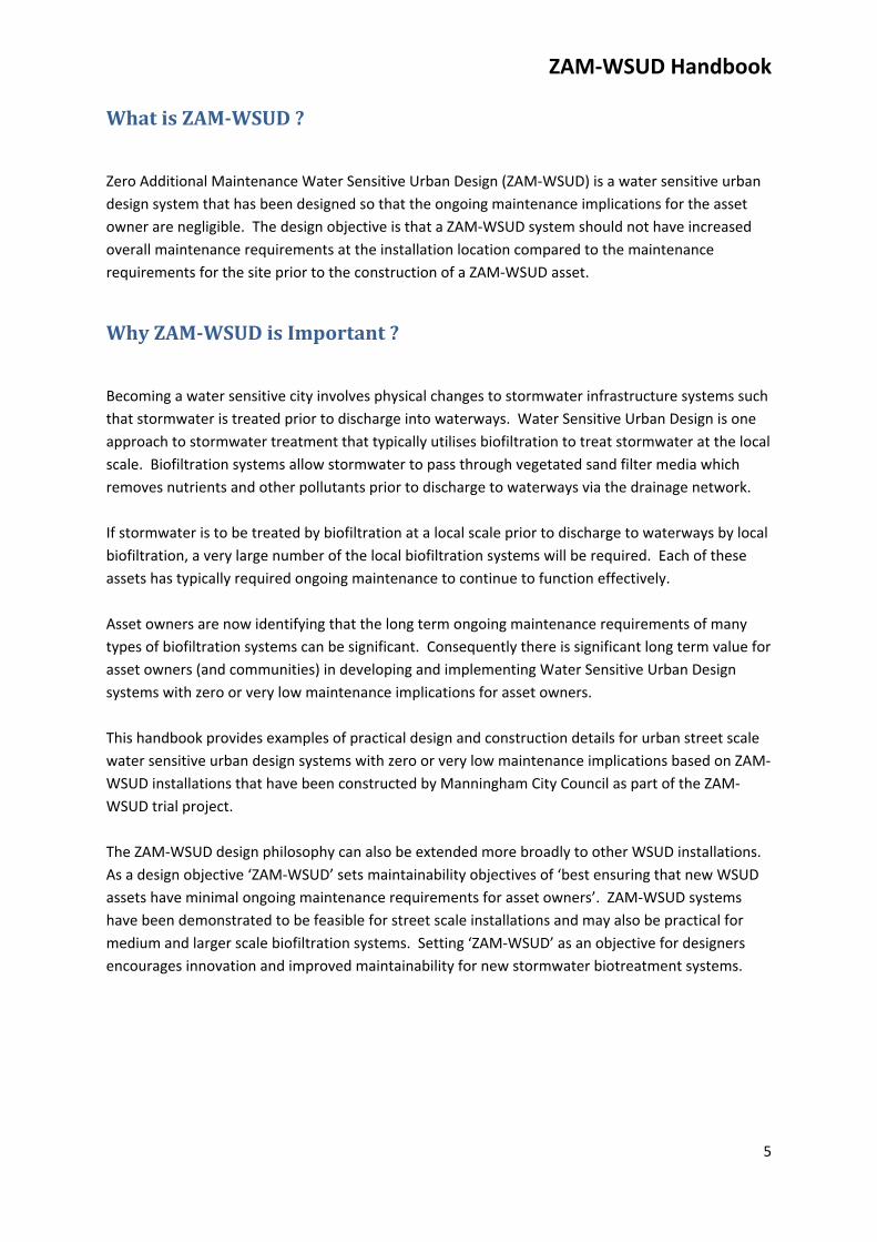
ZAMWSUDInitiatives
The ZAM‐WSUD research project investigated typical maintenance requirements for street scale
water sensitive urban design systems, and adopted various alternative design solutions that
removed ongoing maintenance requirements for asset owners.
Design solutions implemented in the ZAM‐WSUD trials were:
Sediment grooves
Grass turf for biofiltration
‘Clog resistant’ filter media profile
Litter guard inlets
ZAM‐WSUD designs were developed primarily for the retrofit of typical suburban residential
streetscapes with grassed nature strips, but are also suitable for new urban developments, car
parking areas and industrial sites.
Schematic of a grassed ZAM‐WSUD installation
ZAM‐WSUD Handbook
7
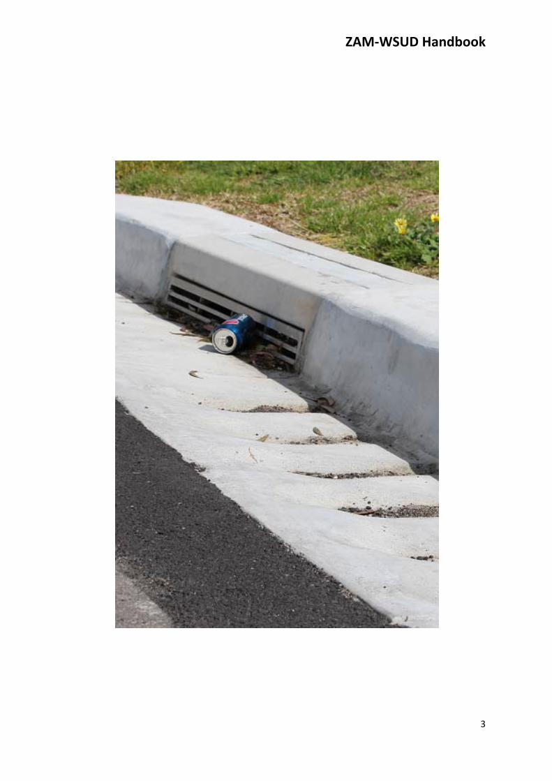
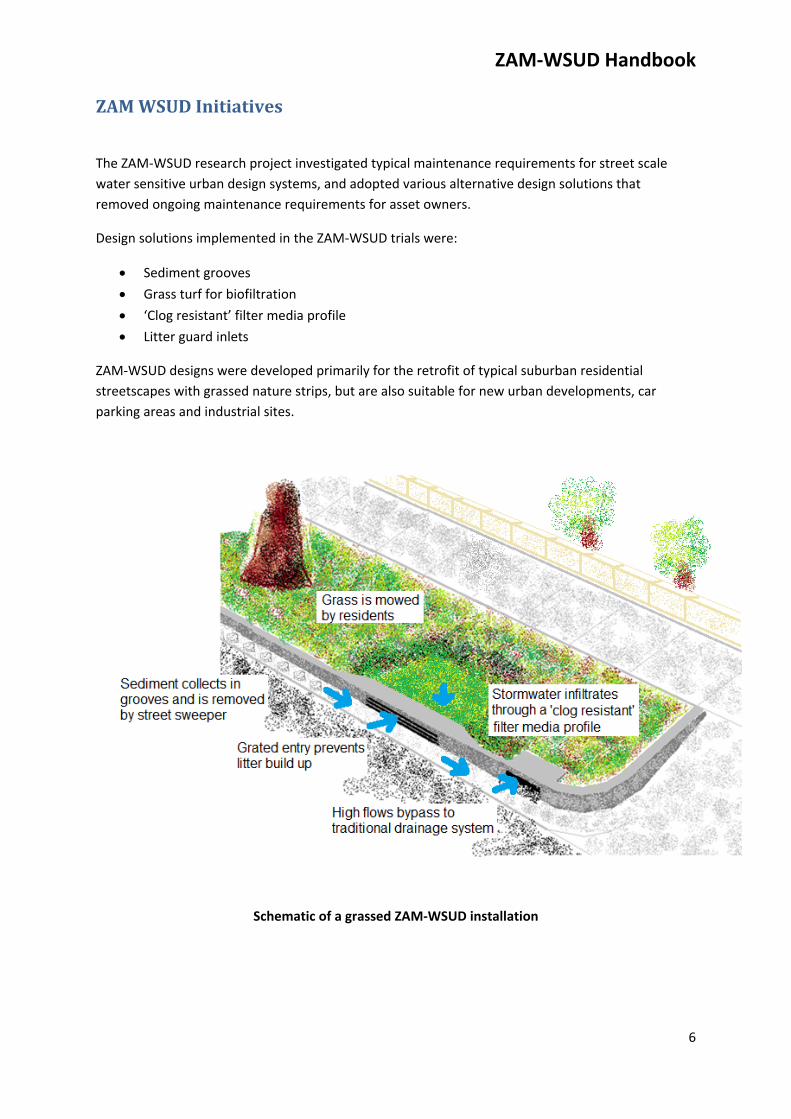
SedimentgroovesBiofiltration systems can be susceptible to filter media clogging if large amounts of fine sediment
(typically silts) enter the biofiltration system and form a thin impervious surface layer, preventing
water entry to subsurface layers.
Sediment collection prior to a biofiltration system reduces sediment quantities entering the biofilter,
reducing the risk of clogging and helping to ensure that systems can function effectively in the long
term without requiring sediment removal and/or filter media replacement.
Appropriately dimensioned sediment grooves constructed in the concrete channel prior to a biofilter
inlet have been shown to be effective at trapping sediment.
Deposition in a sediment grove prototype Constructed sediment grooves
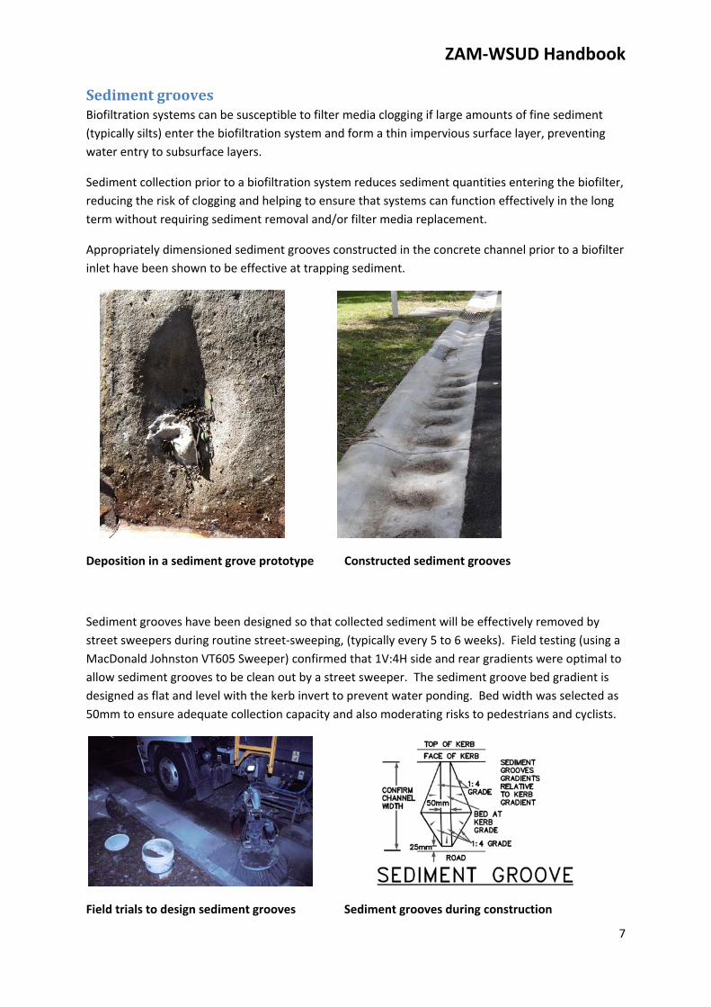
Sediment grooves have been designed so that collected sediment will be effectively removed by
street sweepers during routine street‐sweeping, (typically every 5 to 6 weeks). Field testing (using a
MacDonald Johnston VT605 Sweeper) confirmed that 1V:4H side and rear gradients were optimal to
allow sediment grooves to be clean out by a street sweeper. The sediment groove bed gradient is
designed as flat and level with the kerb invert to prevent water ponding. Bed width was selected as
50mm to ensure adequate collection capacity and also moderating risks to pedestrians and cyclists.
Field trials to design sediment grooves Sediment grooves during construction
ZAM‐WSUD Handbook
8
GrassedWSUDSystemsWSUD systems have typically utilised low level riparian vegetation to remove nutrient and other
pollutants during infiltration. Research trials previously undertaken at Monash University (Payne et
Alia, 2014) identified that soft leaf buffalo grass also effectively removes nitrogen and phosphorous
from stormwater passing through a sand filtration system. As such grasses were confirmed as
potentially suitable for WSUD applications.
The ZAM‐WSUD research project identified that grassed biofilter systems could meet the ‘zero
additional maintenance’ objective when installed in a typical suburban nature strip. Normal grass
mowing arrangements (by residents, Council or others) will provide regular removal of vegetation
growth, effectively removing nutrients from the biofiltration system and ensuring that the system
continues to effectively treat stormwater system in the long term.
The Palmetto SS100 soft leafed buffalo cultivar was initially identified as potentially suitable due to
characteristics such as: drought tolerance, shade tolerance, frost tolerance, slow growth rate, wear
tolerance and low growth height. Preliminary field trials undertaken in Manningham in 2014‐16
confirmed that the Palmetto SS100 cultivar could be suitable for in‐field grassed ZAM‐WSUD
installations, but that there could be some establishment difficulties for “full sun” sites with dry soils.
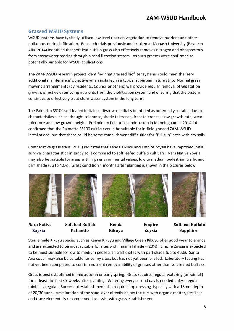
Comparative grass trails (2016) indicated that Kenda Kikuyu and Empire Zoysia have improved initial
survival characteristics in sandy soils compared to soft leafed buffalo cultivars. Nara Native Zoysia
may also be suitable for areas with high environmental values, low to medium pedestrian traffic and
part shade (up to 40%). Grass condition 4 months after planting is shown in the pictures below.
NaraNative SoftleafBuffaloKenda Empire SoftleafBuffalo.Zoysia Palmetto Kikuyu Zoysia Sapphire
Sterile male Kikuyu species such as Kenya Kikuyu and Village Green Kikuyu offer good wear tolerance
and are expected to be most suitable for sites with minimal shade (<20%). Empire Zoysia is expected
to be most suitable for low to medium pedestrian traffic sites with part shade (up to 40%). Santa
Ana couch may also be suitable for sunny sites, but has not yet been trialled. Laboratory testing has
not yet been completed to confirm nutrient removal ability of grasses other than soft leafed buffalo.
Grass is best established in mid autumn or early spring. Grass requires regular watering (or rainfall)
for at least the first six weeks after planting. Watering every second day is needed unless regular
rainfall is regular. Successful establishment also requires top dressing, typically with a 15mm depth
of 20/30 sand. Amelioration of the sand layer directly below the turf with organic matter, fertiliser
and trace elements is recommended to assist with grass establishment.
ZAM‐WSUD Handbook
9
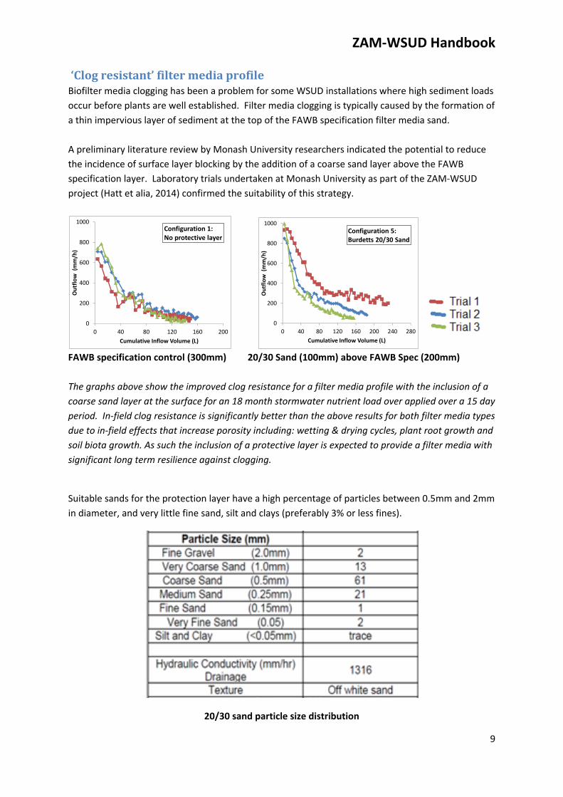
‘Clogresistant’filtermediaprofileBiofilter media clogging has been a problem for some WSUD installations where high sediment loads
occur before plants are well established. Filter media clogging is typically caused by the formation of
a thin impervious layer of sediment at the top of the FAWB specification filter media sand.
A preliminary literature review by Monash University researchers indicated the potential to reduce
the incidence of surface layer blocking by the addition of a coarse sand layer above the FAWB
specification layer. Laboratory trials undertaken at Monash University as part of the ZAM‐WSUD
project (Hatt et alia, 2014) confirmed the suitability of this strategy.
FAWB specification control (300mm) 20/30 Sand (100mm) above FAWB Spec (200mm)
The graphs above show the improved clog resistance for a filter media profile with the inclusion of a
coarse sand layer at the surface for an 18 month stormwater nutrient load over applied over a 15 day
period. In‐field clog resistance is significantly better than the above results for both filter media types
due to in‐field effects that increase porosity including: wetting & drying cycles, plant root growth and
soil biota growth. As such the inclusion of a protective layer is expected to provide a filter media with
significant long term resilience against clogging.
Suitable sands for the protection layer have a high percentage of particles between 0.5mm and 2mm
in diameter, and very little fine sand, silt and clays (preferably 3% or less fines).
20/30 sand particle size distribution
0
200
400
600
800
1000
0 40 80 120 160 200
Outflow (mm/h)
Cumulative Inflow Volume (L)
Configuration 1:No protective layer
0
200
400
600
800
1000
0 40 80 120 160 200 240 280
Outflow (mm/h)
Cumulative Inflow Volume (L)
Configuration 5:Burdetts 20/30 Sand
ZAM‐WSUD Handbook
10
LitterguardinletsTypical biofilter systems are designed to allow litter to enter the filtration area where it will be
retained on the surface. This has benefits in terms preventing litter entry to waterways, but also has
maintenance implications as community expectations are that litter is regularly removed from
WSUD assets. Community expectations for litter removal can create significant ongoing
maintenance requirements for asset owners.
ZAM‐WSUD systems installed in trials included inlet grates with 18mm to 20mm gaps between bars
such that larger litter will continue along the kerb and bypass the biofiltration system. Square bars
were used to reduce the potential for litter to jam between bars. Litter smaller than 20mm in size is
able pass through the inlet grates. This sized litter would generally be expected to be collected
during grass mowing. Inlet grates have also been designed so that the inlet grill is flush with the
existing kerb so that the face can be effectively cleaned by street sweepers as part of normal street
sweeping. Bypass flow will also assist in removing leaf matter and other debris from the face of the
inlet grate. In‐field observations confirm that the design is effective at ensuring that there is no long
term collection of debris on the inlet grate.
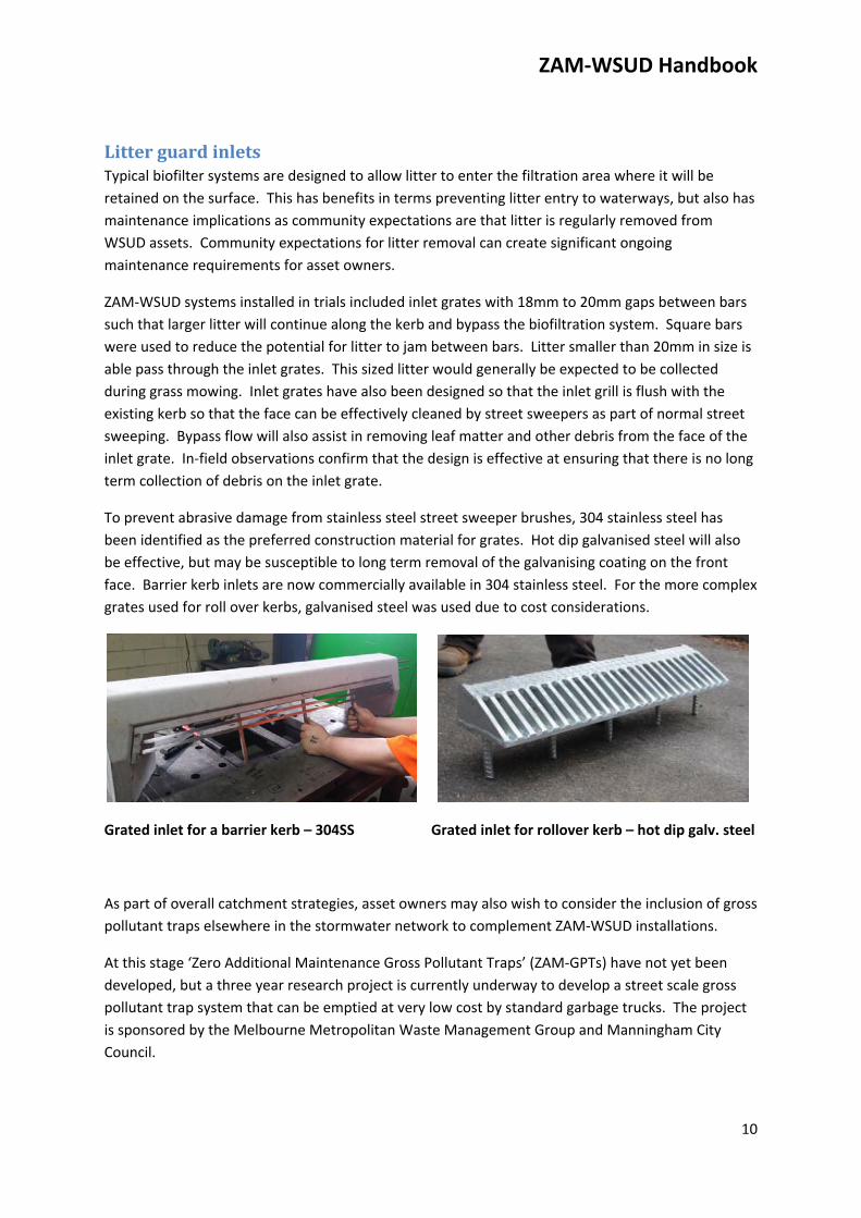
To prevent abrasive damage from stainless steel street sweeper brushes, 304 stainless steel has
been identified as the preferred construction material for grates. Hot dip galvanised steel will also
be effective, but may be susceptible to long term removal of the galvanising coating on the front
face. Barrier kerb inlets are now commercially available in 304 stainless steel. For the more complex
grates used for roll over kerbs, galvanised steel was used due to cost considerations.
Grated inlet for a barrier kerb – 304SS Grated inlet for rollover kerb – hot dip galv. steel
As part of overall catchment strategies, asset owners may also wish to consider the inclusion of gross
pollutant traps elsewhere in the stormwater network to complement ZAM‐WSUD installations.
At this stage ‘Zero Additional Maintenance Gross Pollutant Traps’ (ZAM‐GPTs) have not yet been
developed, but a three year research project is currently underway to develop a street scale gross
pollutant trap system that can be emptied at very low cost by standard garbage trucks. The project
is sponsored by the Melbourne Metropolitan Waste Management Group and Manningham City
Council.
ZAM‐WSUD Handbook
11
PracticalZAM‐WSUDExamples
Grassed
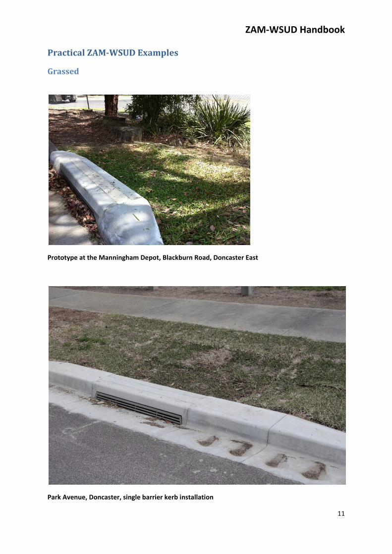
Prototype at the Manningham Depot, Blackburn Road, Doncaster East
Park Avenue, Doncaster, single barrier kerb installation
ZAM‐WSUD Handbook
12
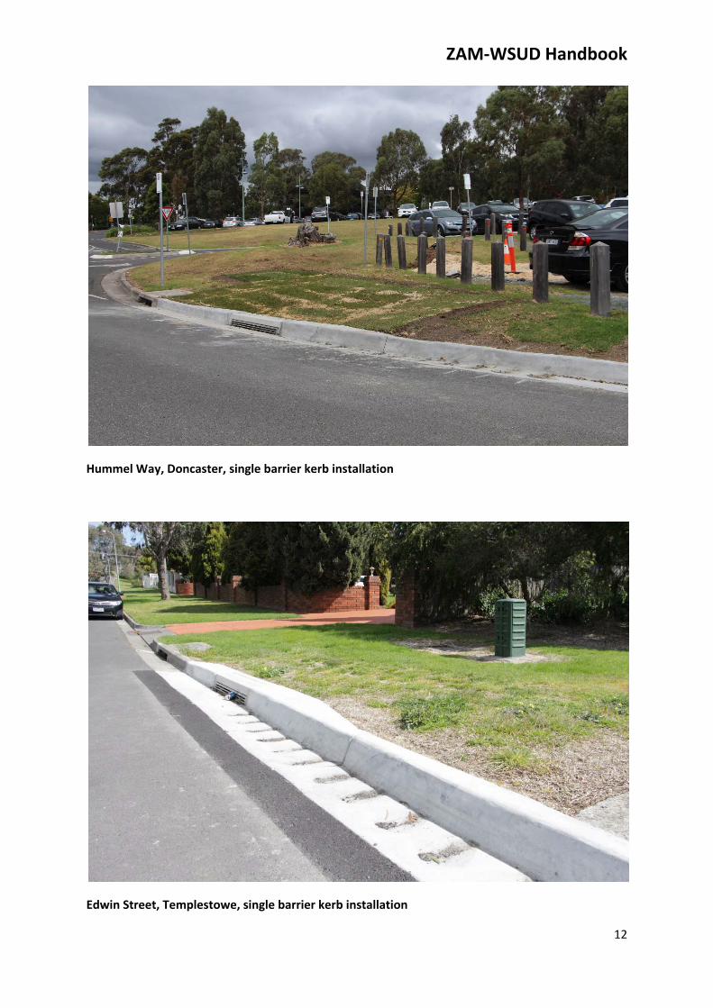
Hummel Way, Doncaster, single barrier kerb installation
Edwin Street, Templestowe, single barrier kerb installation
ZAM‐WSUD Handbook
13
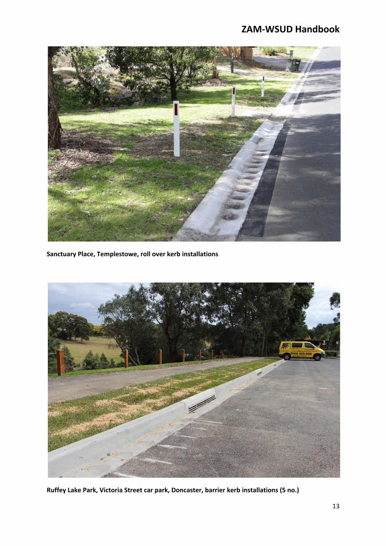
Sanctuary Place, Templestowe, roll over kerb installations
Ruffey Lake Park, Victoria Street car park, Doncaster, barrier kerb installations (5 no.)

ZAM‐WSUD Handbook
14
VegetatedVegetated WSUD systems can also be designed to require no or minimal additional maintenance.
For areas where feature landscaping is existing or proposed for aesthetic reasons, a vegetated ZAM‐
WSUD system can be installed with similar maintenance requirements to a typical landscaped area
such that the design criteria of ‘zero additional maintenance’ is achieved.
For new urban street scale installations, some occasional weed removal and vegetation trimming
may still be required. Inclusion of a surface layer of 20/30 course sand has been shown to
significantly reduce weed growth in ZAM‐WSUD systems installed to date. The selection of plant
species with low to moderate foliage growth rates will minimise trimming requirements.
Sketch of a typical vegetated ZAM‐WSUD installation
In order to ensure that vegetated ZAM‐WSUD systems are effective at removing nitrogen, systems
should be planted with at least 50% of plants from the list of species recommended in Adoption
Guidelines for Stormwater Biofiltration Systems – Summary Report (Payne et alia, 2015). Suggested
species from this list that are suitable for general installations are: Goodenia ovata, Juncus flavidus,
Baumea rubiginosa and Ficinia nodosa. The remainder of plants can be selected from a broad range
of species, but species that fix nitrogen should be avoided.
ZAM‐WSUD Handbook
15
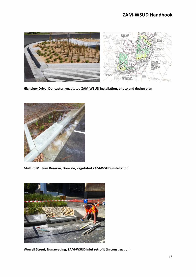
Highview Drive, Doncaster, vegetated ZAM‐WSUD installation, photo and design plan
Mullum Mullum Reserve, Donvale, vegetated ZAM‐WSUD installation
Worrell Street, Nunawading, ZAM‐WSUD inlet retrofit (in construction)
ZAM‐WSUD Handbook
16
SiteSelection
A wide range of factors need to be considered when assessing the suitability of a proposed site for a
ZAM‐WSUD system.
StrategicplanningWSUD systems offer greatest benefits to waterways in catchments where there is no other
previously constructed stormwater treatment infrastructure, (such as a treatment wetland). As such
installations are most beneficial when strategically coordinated in accordance with an overall
stormwater management plan for the catchment.
CatchmentareaandsizeWSUD systems aim to break the direct link between impervious areas and the stormwater network.
To be most effective systems should generally be located just upstream of a side entry or grated
stormwater pit to allow stormwater from the largest catchment to be collected and treated.
The ZAM‐WSUD system size needs to be proportional to the impervious catchment area size that
drains into the biofilter to ensure that systems provide effective stormwater treatment and are
resistant to clogging.
A treatment area of 1‐2% of the impervious catchment area is considered ideal for biofiltration
systems. ZAM‐WSUD systems are expected to be able function effectively with larger catchment
areas compared to traditional WSUD systems as ZAM‐WSUD systems include additional measures to
provide resilience to clogging, i.e. sediment grooves and the modified filter media profile.
Small sized, single inlet ZAM‐WSUD systems with a 2m2 treatment area are expected to be effective
for impervious catchment areas between approximately 100m2 and 400m2.
SuitableroadgradientsGrassed ZAM‐WSUD systems have been constructed and are operating successfully on roads with
gradients up to 1V:10H. There may be some soil movement during the grass establishment phase
for ZAM‐WSUD systems on roads with gradients close to 1V:10H.
For roads with steeper gradients than 1V:10H, it may be difficult to design mowable ZAM‐WSUD
systems with batters that do not exceed 1V:5H that can adequately contain water. Additional
velocity control measures may also be required at the inlet to reduce velocities to prevent scouring.
UndergroundservicesConflicts with existing underground services can make ZAM‐WSUD retrofit installations impractical
and/or very costly in many instances. As road reserves typically contain many underground services,

ZAM‐WSUD Handbook
17
it essential to obtain underground services information when assessing the suitability of a potential
ZAM‐WSUD site.
Excavation clearance distances to power poles in accordance with authority requirements also need
to be considered.
ZAM‐WSUD systems require a connection to the piped drainage network, preferably to an existing
stormwater pit. Consequently ZAM‐WSUD systems are most cost effective when constructed in
close proximity to existing drainage assets, preferably an existing drainage pit.
StreetTreesZAM‐WSUD systems should be constructed away from trees and large shrubs to minimise the
potential for tree root entry into ag drains.
VehiclecompactionVehicles parking on, or driving over, biofilter systems will compact the filter media reducing
hydraulic conductivity. This can increase susceptibility to clogging. Consequently systems should be
located where the incidence of vehicles parking on the nature strip is expected to be low, or can be
controlled by physical barriers.
NaturestripwidthandgradientGrassed ZAM‐WSUD systems are generally practical where the nature strip width is at least 2m wide
and the footpath level is not significantly elevated (more than 10cm) above the level of the top of
kerb. This ensures pedestrian safety and mowability by ensuring that batter slopes generally do not
exceed 1V:5H.
Generally vegetated ZAM‐WSUD systems can be constructed where the nature strip width is at least
1.5m wide.
ResidentandcommunityacceptanceofZAM‐WSUDassetsGaining local community acceptance of ZAM‐WSUD assets is essential to any successful installation.
This is particularly important for installations outside residential properties where residents will be
responsible for mowing of the grass. For these installations it is appropriate to engage residents as
part of the site selection process. If residents are unsupportive, it may be appropriate to seek an
alternative location for the ZAM‐WSUD asset. An asset which has received acceptance from
adjacent residents prior to construction will have a far better long term prospects than an asset that
has been installed without appropriate consultation and/or acceptance.
One strategy that may be appropriate for obtaining resident acceptance is to offer a choice between
a grassed and a vegetated ZAM‐WSUD asset.
ZAM‐WSUD Handbook
18
DetailedDesign
Key factors to consider when designing a ZAM‐WSUD system include:
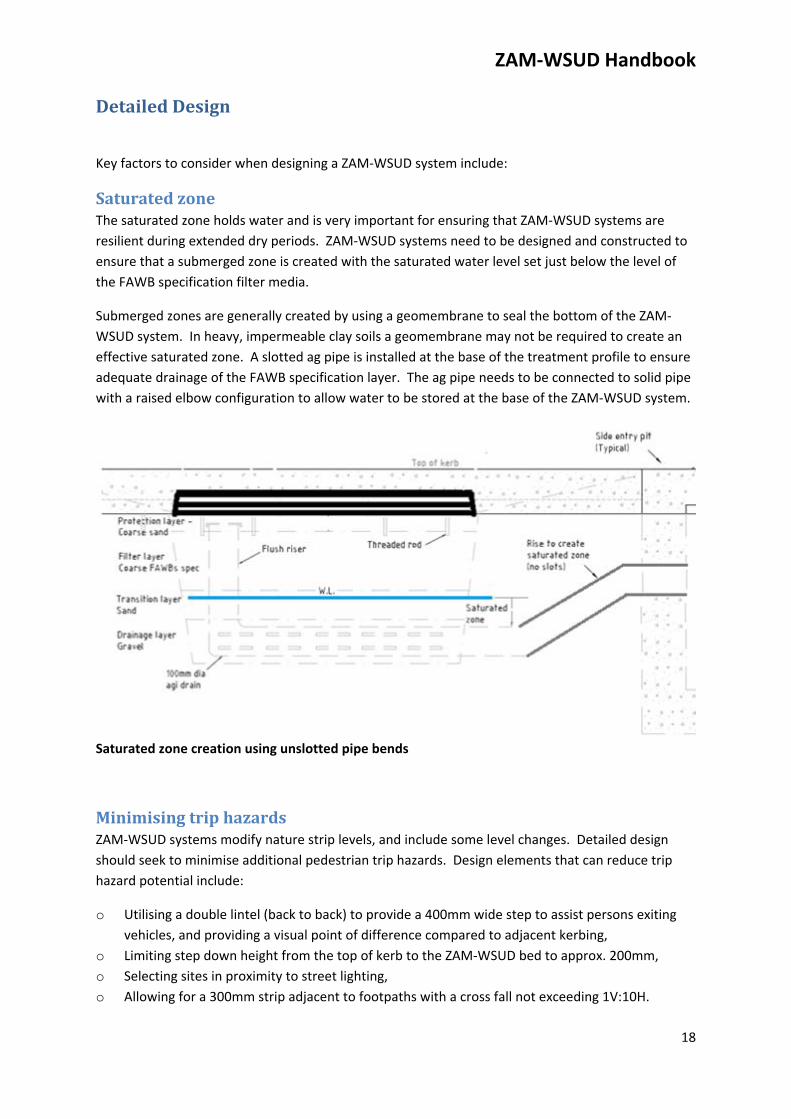
SaturatedzoneThe saturated zone holds water and is very important for ensuring that ZAM‐WSUD systems are
resilient during extended dry periods. ZAM‐WSUD systems need to be designed and constructed to
ensure that a submerged zone is created with the saturated water level set just below the level of
the FAWB specification filter media.
Submerged zones are generally created by using a geomembrane to seal the bottom of the ZAM‐
WSUD system. In heavy, impermeable clay soils a geomembrane may not be required to create an
effective saturated zone. A slotted ag pipe is installed at the base of the treatment profile to ensure
adequate drainage of the FAWB specification layer. The ag pipe needs to be connected to solid pipe
with a raised elbow configuration to allow water to be stored at the base of the ZAM‐WSUD system.
Saturated zone creation using unslotted pipe bends
MinimisingtriphazardsZAM‐WSUD systems modify nature strip levels, and include some level changes. Detailed design
should seek to minimise additional pedestrian trip hazards. Design elements that can reduce trip
hazard potential include:
o Utilising a double lintel (back to back) to provide a 400mm wide step to assist persons exiting
vehicles, and providing a visual point of difference compared to adjacent kerbing,
o Limiting step down height from the top of kerb to the ZAM‐WSUD bed to approx. 200mm,
o Selecting sites in proximity to street lighting,
o Allowing for a 300mm strip adjacent to footpaths with a cross fall not exceeding 1V:10H.
ZAM‐WSUD Handbook
19
NumberofsedimentgroovesFor a typical urban catchment with 150m2 of impervious surface area, 12 no. sediment grooves (as
recommended on the standard drawings) are estimated to have adequate capacity to capture up to
50% of the total suspended solids for the catchment based on street sweeping at 6 week intervals.
For larger catchments sizes it is appropriate to include additional sediment grooves, refer to the
technical specifications.
VandalismprotectionandstructuralintegrityInstallations need to be robust such that they are not susceptible to physical damage or vandalism.
Inlet grates should include legs cast into concrete so that they cannot be removed. Concrete
thickening (to 150mm min) and steel bar reinforcement is appropriate at inlet locations to prevent
cracking.
Excessive cyclic localised saturation and drying of road subgrade and subbase materials can
accelerate structural deterioration and/or subsidence of this material. Including an impermeable
geomembrane layer between the filter media and the road subgrade and subbase materials will limit
localised water inflow to subgrade materials and limit any associated accelerated road pavement
degradation.
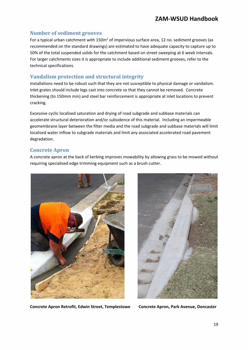
ConcreteApronA concrete apron at the back of kerbing improves mowability by allowing grass to be mowed without
requiring specialised edge trimming equipment such as a brush cutter.
Concrete Apron Retrofit, Edwin Street, Templestowe Concrete Apron, Park Avenue, Doncaster
ZAM‐WSUD Handbook
20
Construction
Many construction requirements will be similar for other road construction works such as concrete
quality control, underground services checks, traffic and pedestrian management plans and in some
cases road opening permits.
Some requirements are specifically relevant to ZAM‐WSUD installations. As many elements of the
ZAM‐WSUD system are relatively new, effective communication and supervision of contractors is
essential to ensure that constructed assets are fit for purpose and achieve the Zero Additional
Maintenance objective.
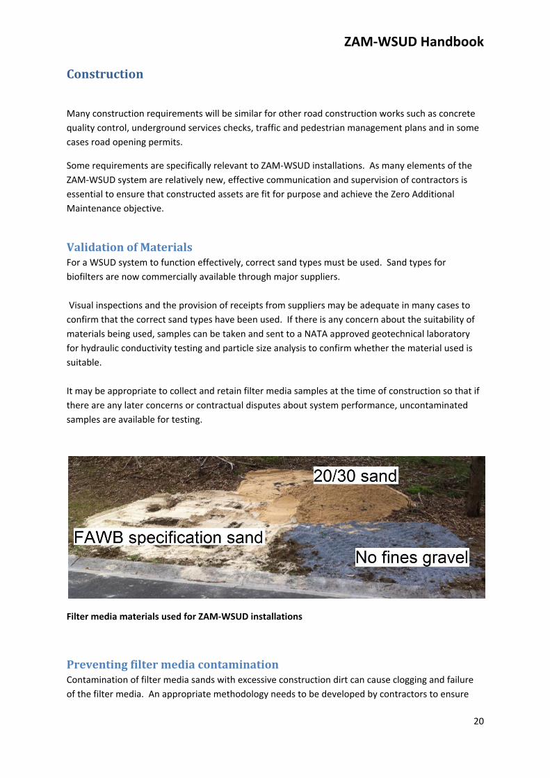
ValidationofMaterialsFor a WSUD system to function effectively, correct sand types must be used. Sand types for
biofilters are now commercially available through major suppliers.
Visual inspections and the provision of receipts from suppliers may be adequate in many cases to
confirm that the correct sand types have been used. If there is any concern about the suitability of
materials being used, samples can be taken and sent to a NATA approved geotechnical laboratory
for hydraulic conductivity testing and particle size analysis to confirm whether the material used is
suitable.
It may be appropriate to collect and retain filter media samples at the time of construction so that if
there are any later concerns or contractual disputes about system performance, uncontaminated
samples are available for testing.
Filter media materials used for ZAM‐WSUD installations
PreventingfiltermediacontaminationContamination of filter media sands with excessive construction dirt can cause clogging and failure
of the filter media. An appropriate methodology needs to be developed by contractors to ensure
ZAM‐WSUD Handbook
21
that this does not occur. Suitable protection measures during construction include placing and
removing a sacrificial sand layer, placing a cover over the filter media and/or blocking the inlet until
the construction site has been fully cleaned.
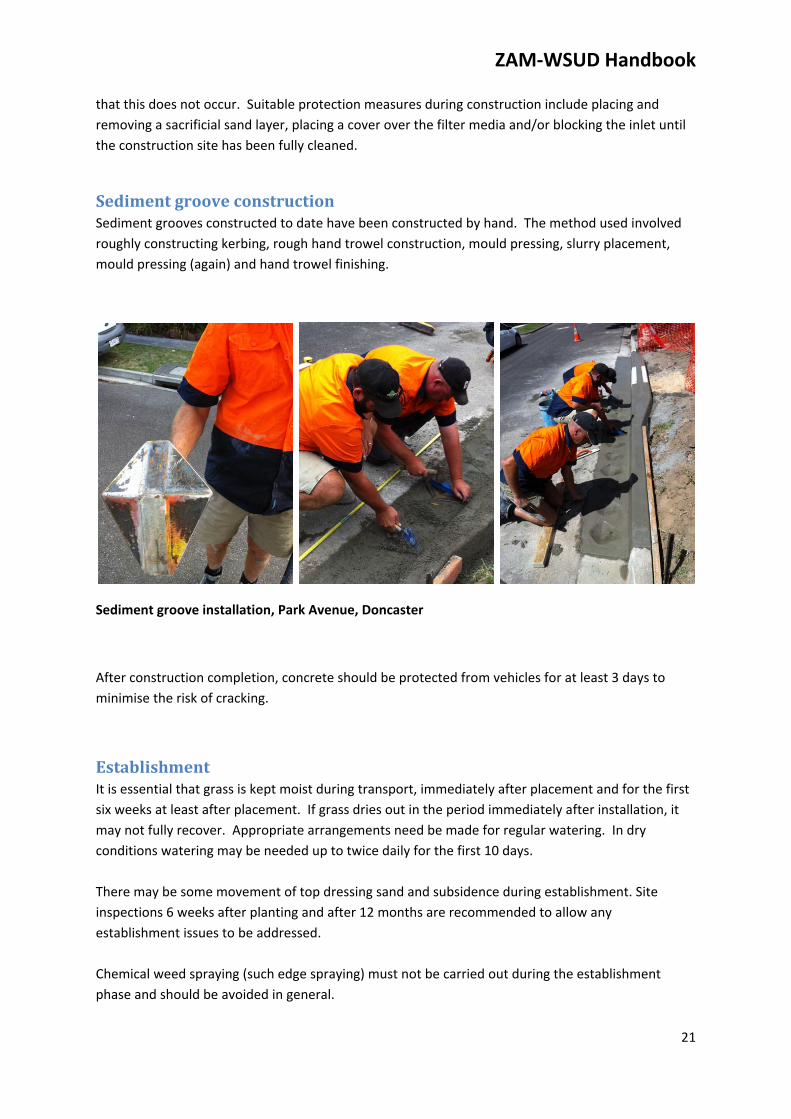
SedimentgrooveconstructionSediment grooves constructed to date have been constructed by hand. The method used involved
roughly constructing kerbing, rough hand trowel construction, mould pressing, slurry placement,
mould pressing (again) and hand trowel finishing.
Sediment groove installation, Park Avenue, Doncaster
After construction completion, concrete should be protected from vehicles for at least 3 days to
minimise the risk of cracking.
EstablishmentIt is essential that grass is kept moist during transport, immediately after placement and for the first
six weeks at least after placement. If grass dries out in the period immediately after installation, it
may not fully recover. Appropriate arrangements need be made for regular watering. In dry
conditions watering may be needed up to twice daily for the first 10 days.
There may be some movement of top dressing sand and subsidence during establishment. Site
inspections 6 weeks after planting and after 12 months are recommended to allow any
establishment issues to be addressed.
Chemical weed spraying (such edge spraying) must not be carried out during the establishment
phase and should be avoided in general.
ZAM‐WSUD Handbook
22
References Belinda Hatt, Veljko Prodanovic & Ana Deletic (2014) Zero Additional Maintenance WSUD Systems: Clogging Potential of Alternative Filter Media Arrangements. Monash University Water for Liveability Centre Emily G. I. Payne, Tracey Pham, Perran L. M. Cook, Tim D. Fletcher, Belinda E. Hatt & Ana Deletic (2014) Biofilter design for effective nitrogen removal from stormwater – influence of plant species, inflow hydrology and use of a saturated zone. Water Science and Technology 69.6. FAWB (2009) Adoption Guidelines for Stormwater Biofiltration Systems, Facility for Advancing Water Biofiltration, Monash University Payne et alia (2015) Adoption Guidelines for Stormwater Biofiltration Systems – Summary Report, Cooperative Research Centre for Water Sensitive Cities
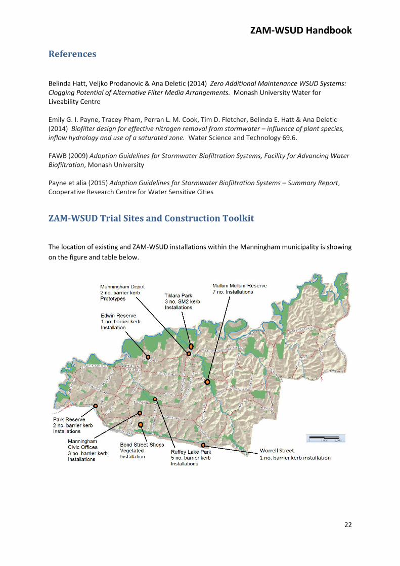
ZAM‐WSUDTrialSitesandConstructionToolkit
The location of existing and ZAM‐WSUD installations within the Manningham municipality is showing
on the figure and table below.
ZAM‐WSUD Handbook
23
Site
Address Suburb
Melways
Reference
Manningham Depot 620‐628 Blackburn Road
(staff car park) Doncaster East 34 D3
Tikilara Park Sanctuary Place Templestowe 34E1
Manningham Civic
Offices Hummel Way Doncaster 33F12
Ruffey Lake Park
Victoria Street Car Park Doncaster 33J10
Park Reserve
Park Avenue Doncaster 32J12
Edwin Reserve
Edwin Road Templestowe 33G3
Bond Street Shops
Corner Bond Street and
Highview Drive Doncaster 47F2
Mullum Mullum
Reserve
Corner Reynolds and
Springvale Roads Donvale 34H7
Worrell Street Shops Worrell Street Nunawading 48G6
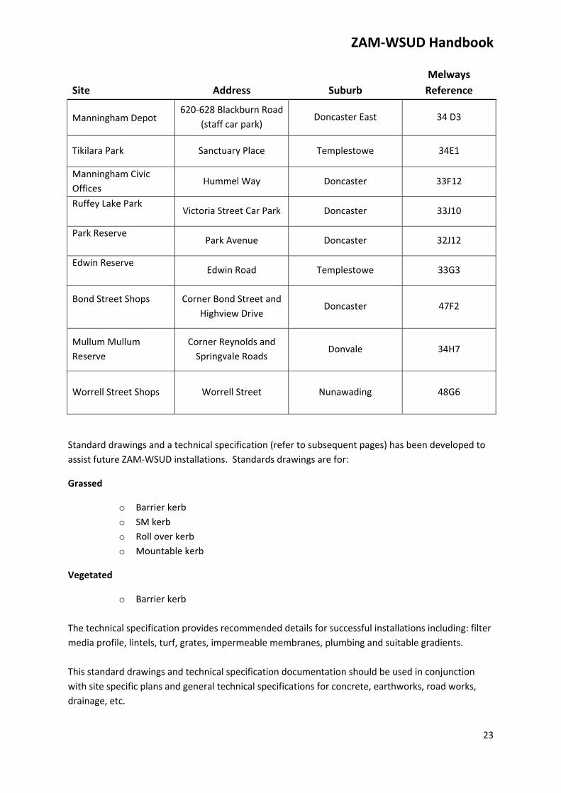
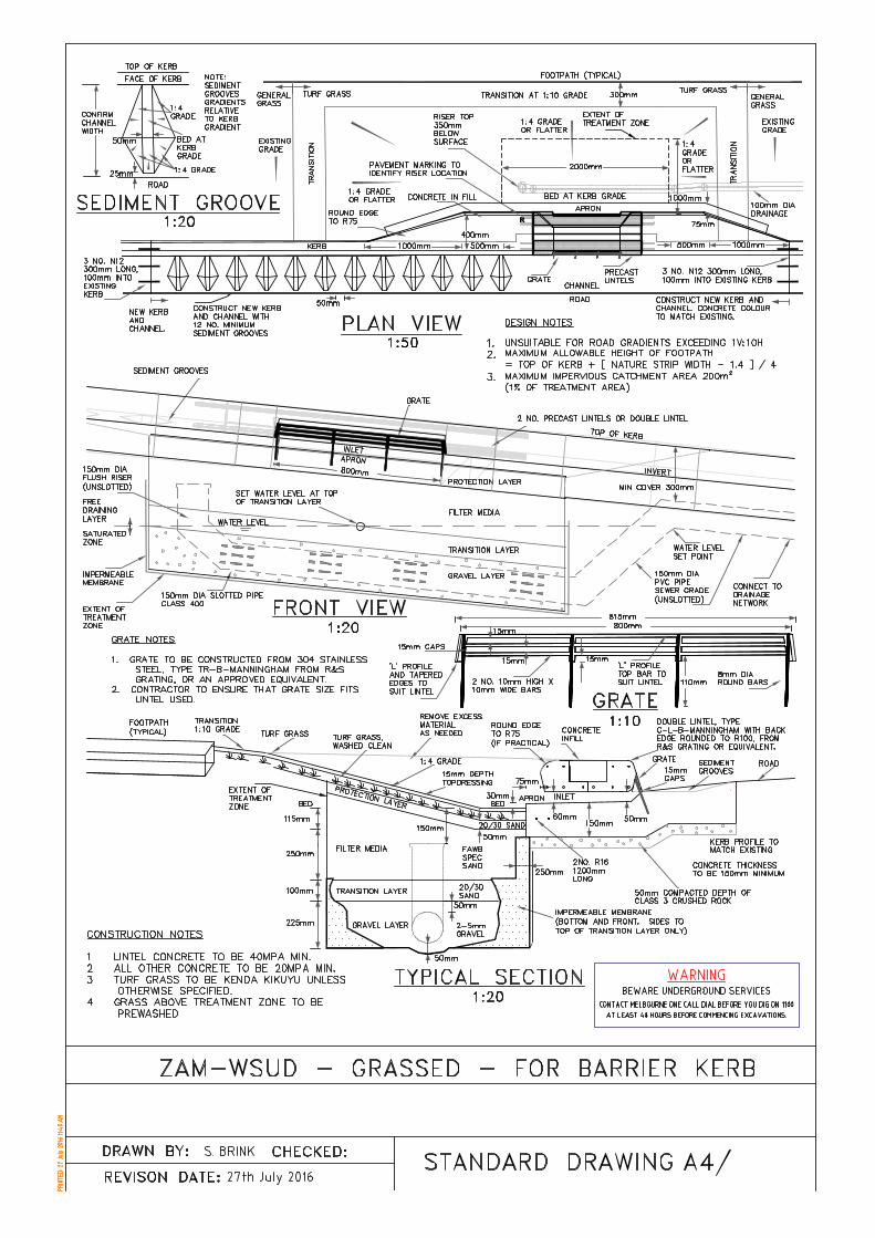
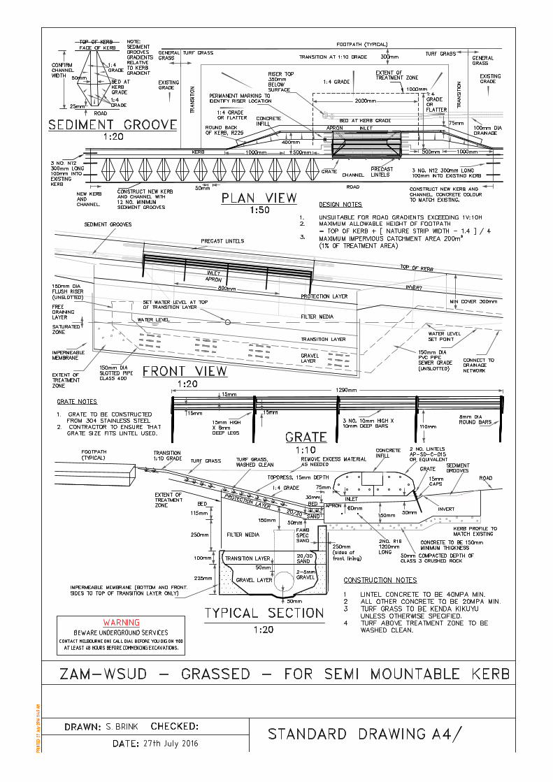
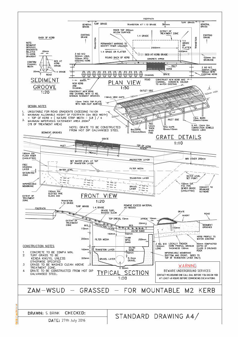
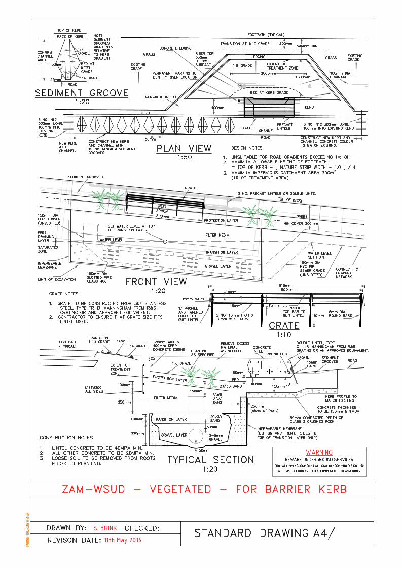
Standard drawings and a technical specification (refer to subsequent pages) has been developed to
assist future ZAM‐WSUD installations. Standards drawings are for:
Grassed
o Barrier kerb
o SM kerb
o Roll over kerb
o Mountable kerb
Vegetated
o Barrier kerb
The technical specification provides recommended details for successful installations including: filter
media profile, lintels, turf, grates, impermeable membranes, plumbing and suitable gradients.
This standard drawings and technical specification documentation should be used in conjunction
with site specific plans and general technical specifications for concrete, earthworks, road works,
drainage, etc.
R
R
R
R
ZAM-WSUD Zero Additional
Maintenance Water Sensitive Urban Design
Technical Specification
ZAM-WSUD Technical Specification
2
1. General
Zero Additional Maintenance Water Sensitive Urban Design (ZAM-WSUD) installations shall be constructed in accordance with these technical specifications, except where otherwise noted on the design plans.
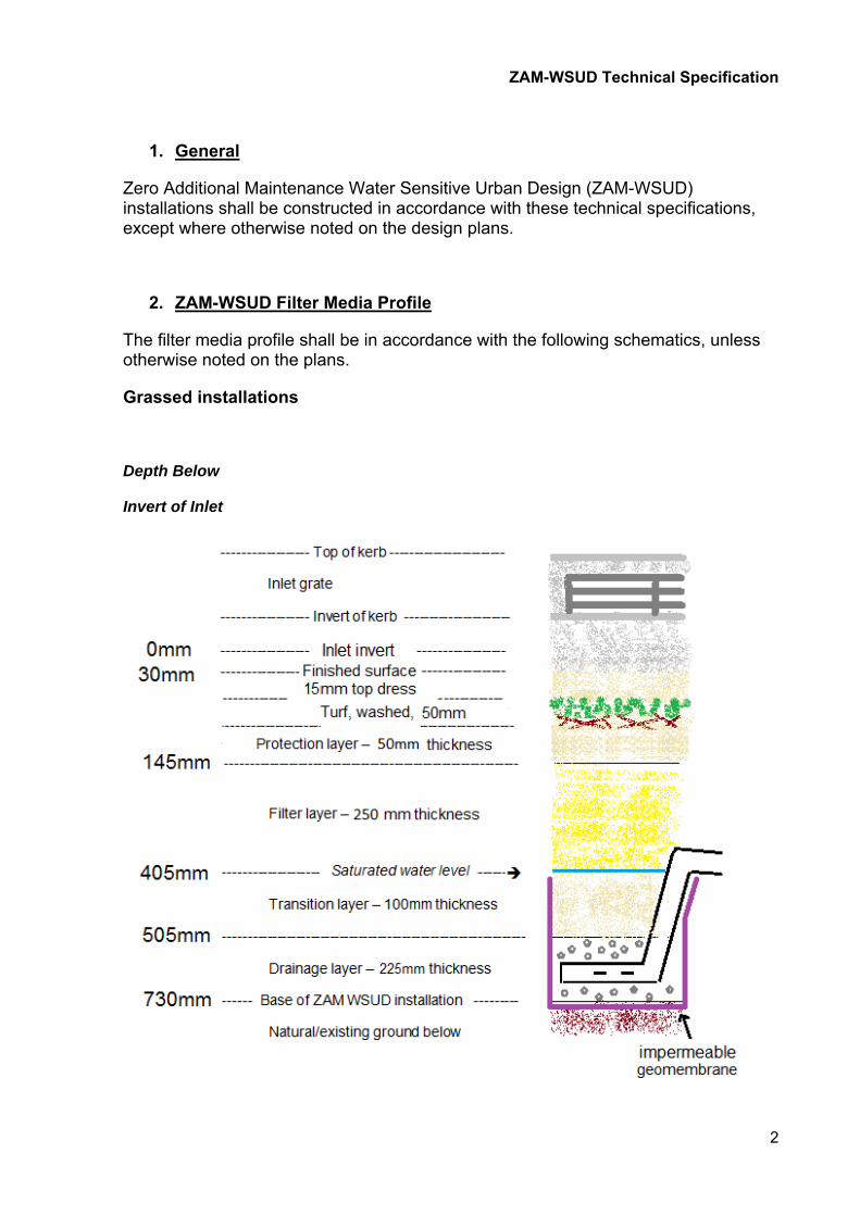
2. ZAM-WSUD Filter Media Profile
The filter media profile shall be in accordance with the following schematics, unless otherwise noted on the plans.
Grassed installations
Depth Below
Invert of Inlet
ZAM-WSUD Technical Specification
3
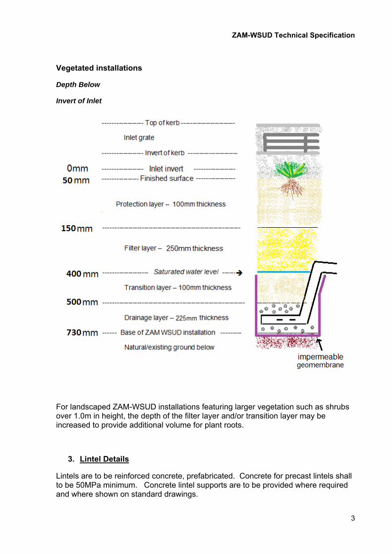
Vegetated installations
Depth Below
Invert of Inlet
For landscaped ZAM-WSUD installations featuring larger vegetation such as shrubs over 1.0m in height, the depth of the filter layer and/or transition layer may be increased to provide additional volume for plant roots.
3. Lintel Details
Lintels are to be reinforced concrete, prefabricated. Concrete for precast lintels shall to be 50MPa minimum. Concrete lintel supports are to be provided where required and where shown on standard drawings.
ZAM-WSUD Technical Specification
4
4. Inlet grates
Inlet grates for barrier and SM2 kerb shall be constructed from 304 stainless steel and shall be in accordance with the standard drawings. Any bolts or fixings in contact with the grate must also be 304 stainless steel (or a similar compatible stainless steel).
Suitable product: R&S Grating – Trash Rack - TR-B-MANNINGHAM
Inlet grates for rollover and mountable kerb shall be hot dip galvanized steel and shall be in accordance with the standard drawings. Any bolts or fixings in contact with the grate must also be hot dip galvanized.
Suitable product: R&S Grating - Trash Rack - TR-SM-MANNINGHAM
Note: SM2 kerb requires a TR-B grate not a TR-SM grate.
Samples of all fabricated steel grates shall be approved by the superintendent/ superintendent’s representative prior to installation.
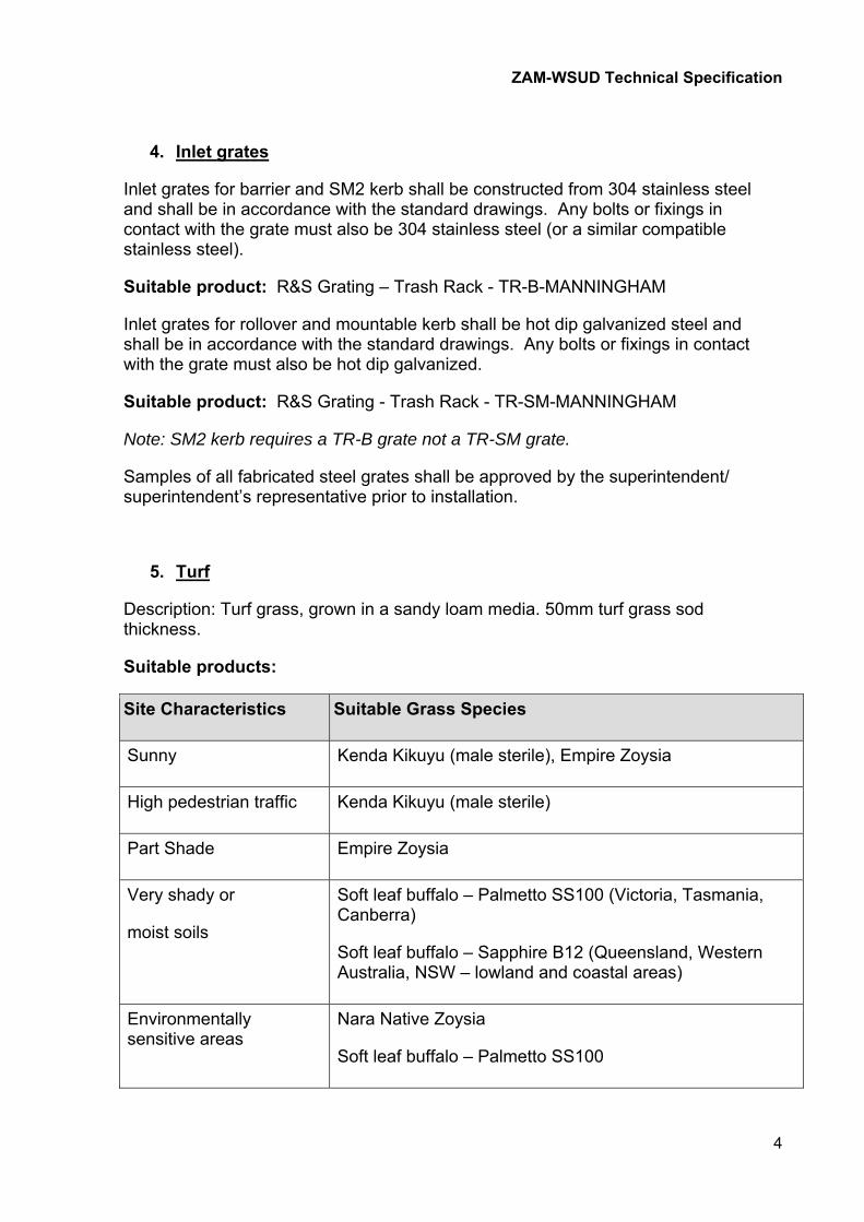
5. Turf
Description: Turf grass, grown in a sandy loam media. 50mm turf grass sod thickness.
Suitable products:
Site Characteristics Suitable Grass Species
Sunny Kenda Kikuyu (male sterile), Empire Zoysia
High pedestrian traffic Kenda Kikuyu (male sterile)
Part Shade Empire Zoysia
Very shady or
moist soils
Soft leaf buffalo – Palmetto SS100 (Victoria, Tasmania, Canberra)
Soft leaf buffalo – Sapphire B12 (Queensland, Western Australia, NSW – lowland and coastal areas)
Environmentally sensitive areas
Nara Native Zoysia
Soft leaf buffalo – Palmetto SS100
ZAM-WSUD Technical Specification
5
Turf placed directly above filter media profile must be made free of significant amounts of loose clay soil material by pressure washing to the satisfaction of the superintendent/ superintendent’s representative prior to placement. Turf placed elsewhere does not need to be washed.
Turf should be grown in a sand or sandy loam media to allow ease of cleaning prior to placement. Note that turf survival time is relatively short, so contractors need to ensure that all turf is planted within 24 hours of delivery to best ensure turf survival. It is recommended that the contractor contract turf suppliers as early as possible to ensure supply at the required time.
Turf must be well watered immediately after planting, every day for the first ten days (twice per day if conditions are dry and warm), and every two to three days subsequently (unless significant rain has fallen) for the first month after planting. Grass needs to be thoroughly watered. Minimum watering volumes can be determined by Bureau of Meteorology evapotranspiration (ETo) data from the closest weather station available at www.bom.gov.au/watl/eto/ Watering volumes must exceed net rainfall deficit (Net = Rainfall – ETo). If planting is done in late spring or summer, turf must be watered regularly for the first three months. Watering is the contractor’s responsibility, unless otherwise specified.
6. Planting
The Adoption Guidelines for Stormwater Biofiltration Systems – Summary Report, CRC for Water Sensitive Cities, 2016, recommends that at least 50% of the vegetation cover in WSUD systems should be plants that have been confirmed as high nutrient uptake plants. The remaining plants can be selected for other attributes such as aesthetics, local biodiversity, etc.
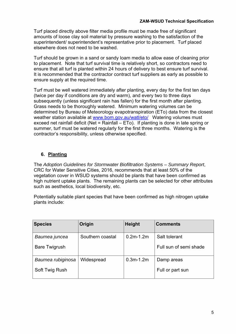
Potentially suitable plant species that have been confirmed as high nitrogen uptake plants include:
Species Origin Height Comments
Baumea juncea
Bare Twigrush
Southern coastal 0.2m-1.2m Salt tolerant
Full sun of semi shade
Baumea rubiginosa
Soft Twig Rush
Widespread 0.3m-1.2m Damp areas
Full or part sun
ZAM-WSUD Technical Specification
6
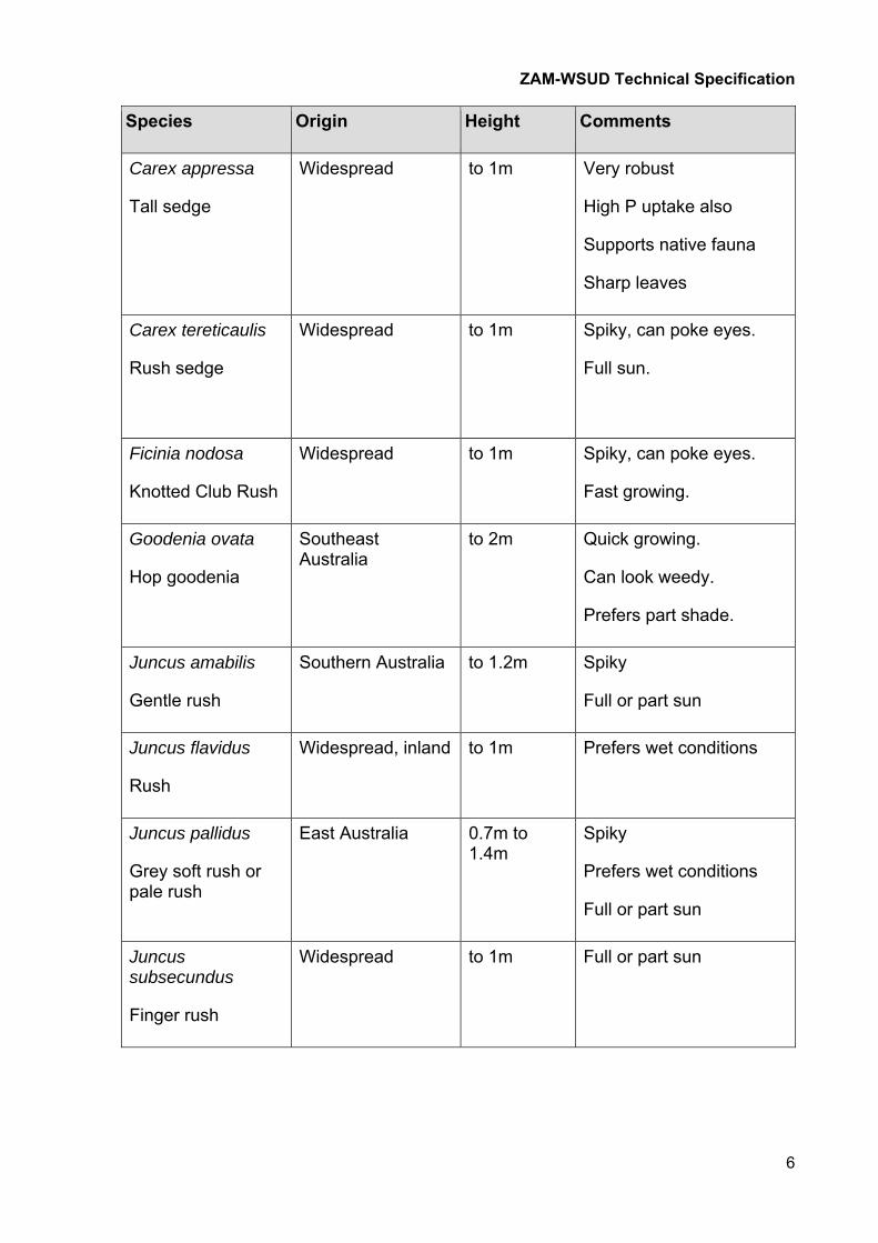
Species Origin Height Comments
Carex appressa
Tall sedge
Widespread to 1m Very robust
High P uptake also
Supports native fauna
Sharp leaves
Carex tereticaulis
Rush sedge
Widespread to 1m Spiky, can poke eyes.
Full sun.
Ficinia nodosa
Knotted Club Rush
Widespread to 1m Spiky, can poke eyes.
Fast growing.
Goodenia ovata
Hop goodenia
Southeast Australia
to 2m Quick growing.
Can look weedy.
Prefers part shade.
Juncus amabilis
Gentle rush
Southern Australia to 1.2m Spiky
Full or part sun
Juncus flavidus
Rush
Widespread, inland to 1m Prefers wet conditions
Juncus pallidus
Grey soft rush or pale rush
East Australia 0.7m to 1.4m
Spiky
Prefers wet conditions
Full or part sun
Juncus subsecundus
Finger rush
Widespread to 1m Full or part sun
ZAM-WSUD Technical Specification
7
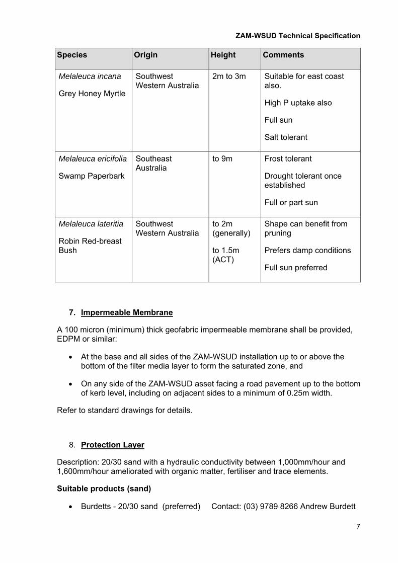
Species Origin Height Comments
Melaleuca incana
Grey Honey Myrtle
Southwest Western Australia
2m to 3m Suitable for east coast also.
High P uptake also
Full sun
Salt tolerant
Melaleuca ericifolia
Swamp Paperbark
Southeast Australia
to 9m Frost tolerant
Drought tolerant once established
Full or part sun
Melaleuca lateritia
Robin Red-breast Bush
Southwest Western Australia
to 2m (generally)
to 1.5m (ACT)
Shape can benefit from pruning
Prefers damp conditions
Full sun preferred
7. Impermeable Membrane
A 100 micron (minimum) thick geofabric impermeable membrane shall be provided, EDPM or similar:
At the base and all sides of the ZAM-WSUD installation up to or above the bottom of the filter media layer to form the saturated zone, and
On any side of the ZAM-WSUD asset facing a road pavement up to the bottom of kerb level, including on adjacent sides to a minimum of 0.25m width.
Refer to standard drawings for details.
8. Protection Layer
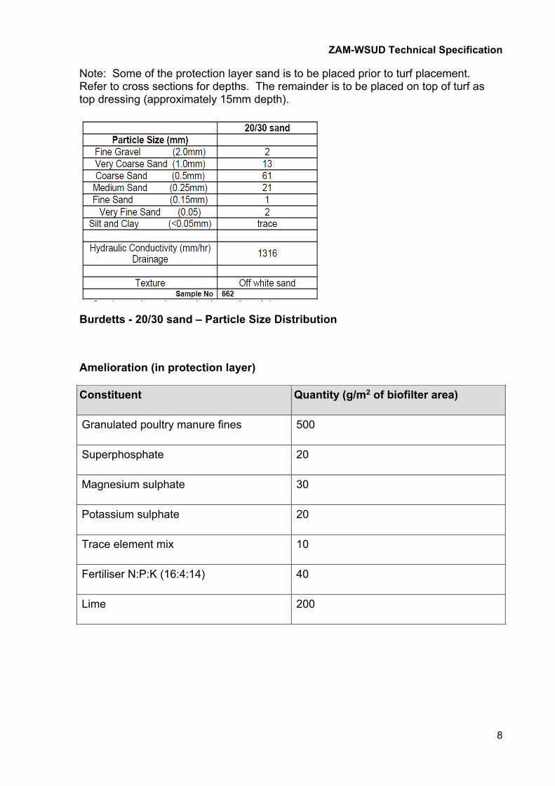
Description: 20/30 sand with a hydraulic conductivity between 1,000mm/hour and 1,600mm/hour ameliorated with organic matter, fertiliser and trace elements.
Suitable products (sand)
Burdetts - 20/30 sand (preferred) Contact: (03) 9789 8266 Andrew Burdett
ZAM-WSUD Technical Specification
8
Note: Some of the protection layer sand is to be placed prior to turf placement. Refer to cross sections for depths. The remainder is to be placed on top of turf as top dressing (approximately 15mm depth).
Burdetts - 20/30 sand – Particle Size Distribution
Amelioration (in protection layer)
Constituent Quantity (g/m2 of biofilter area)
Granulated poultry manure fines 500
Superphosphate 20
Magnesium sulphate 30
Potassium sulphate 20
Trace element mix 10
Fertiliser N:P:K (16:4:14) 40
Lime 200

ZAM-WSUD Technical Specification
9
9. Filter Layer
Description: FAWB specification sand
FAWB Specification – Particle Size Distribution
Suitable products
Daisys - Bio Drain Filter Sand
Daisys - Bio Drain Filter Sand – Particle Size Distribution
ZAM-WSUD Technical Specification
10
10. Transition Layer
Description: 20/30 sand with a hydraulic conductivity of at least 1,000 mm/hour.
Suitable products
Burdetts - 20/30 sand Contact: (03) 9789 8266 Andrew Burdett
Refer to particle size distribution information above.
11. Drainage Layer
Description: No fines gravel, 2.5mm nominal diameter screenings. Screenings generally range in size between approx. 1.5mm and 4mm diameter.
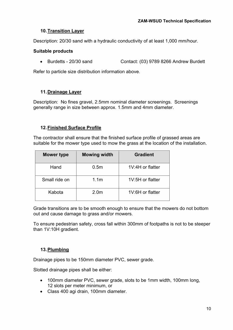
12. Finished Surface Profile
The contractor shall ensure that the finished surface profile of grassed areas are suitable for the mower type used to mow the grass at the location of the installation.
Mower type Mowing width Gradient
Hand 0.5m 1V:4H or flatter
Small ride on 1.1m 1V:5H or flatter
Kabota 2.0m 1V:6H or flatter
Grade transitions are to be smooth enough to ensure that the mowers do not bottom out and cause damage to grass and/or mowers.
To ensure pedestrian safety, cross fall within 300mm of footpaths is not to be steeper than 1V:10H gradient.
13. Plumbing
Drainage pipes to be 150mm diameter PVC, sewer grade.
Slotted drainage pipes shall be either:
100mm diameter PVC, sewer grade, slots to be 1mm width, 100mm long, 12 slots per meter minimum, or
Class 400 agi drain, 100mm diameter.
ZAM-WSUD Technical Specification
11
14. Concrete Apron
For grassed installations, to allow maintenance of grass directly behind the back of kerb without requiring the use of an edge trimmer, a concrete apron shall be provided at the back of the kerb. The concrete apron shall be 75mm wide minimum, 150mm thickness. Top of the concrete shall match the finished surface level of the 20/30 protection layer prior to the placement of turf.
A concrete apron is not required for vegetated installations.
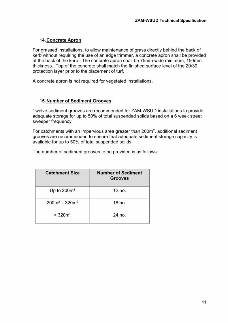
15. Number of Sediment Grooves
Twelve sediment grooves are recommended for ZAM-WSUD installations to provide adequate storage for up to 50% of total suspended solids based on a 6 week street sweeper frequency.
For catchments with an impervious area greater than 200m2, additional sediment grooves are recommended to ensure that adequate sediment storage capacity is available for up to 50% of total suspended solids.
The number of sediment grooves to be provided is as follows:
Catchment Size Number of Sediment Grooves
Up to 200m2 12 no.
200m2 – 320m2 18 no.
> 320m2 24 no.

ZAM-WSUD Technical Specification
12
16. Construction Inspections
The superintendent/superintendent’s representative shall be provided with the opportunity to inspect works at each site at the following stages:
At set out.
Completion of impermeable membrane placement and plumbing works, prior to placement of gravel drainage material.
Completion of placement of any subsequent layers at the request of the superintendent/superintendent’s representative.
A minimum of 24 hours notice is to be given by the contractor prior to any inspections.
Photos shall be taken at the completion of each layer, including showing evidence of the finished level of the top of each layer using a tape measure of similar.
17. Site Clean Up and Maintenance
Contractors are responsible for restoration, clean up and maintenance of all sites at the completion of construction and throughout the defects liability period to the satisfaction of the superintendent/superintendent’s representative.
This includes:
watering of planted turf and grass for 6 weeks after planting (unless otherwise specified).
the replacement of grass in any areas where establishment has been unsuccessful.
Providing additional 20/30 sand fill material to any areas where subsidence has occurred.
18. ZAM-WSUD Trial Site Inspection
Contractors and construction workers shall, where practical, inspect at least one previously completed ZAM-WSUD site prior to commencing construction.
Refer to the ZAM-WSUD handbook for ZAM-WSUD installation locations.