Embed Size (px)
Citation preview

/ B5210
ZAVIO Network Video Recorder
User Manual (Local)
8HDD Series

Table of Contents
1 Introduction ................................................................................... 2
2 Tour the Unit .................................................................................. 3
3 Set up the Unit ............................................................................... 4
3.1 Unpack the Unit................................................................................... 4
3.2 Install 3.5” HDD .................................................................................. 4
3.3 Connect the Unit and Devices ................................................................ 6
3.4 Connect the Monitor ............................................................................. 6
3.5 Power on ............................................................................................ 6
4 First Power-on ................................................................................ 7
4.1 Install Wizard ...................................................................................... 7
5 User Interface .............................................................................. 13
5.1 Live View .......................................................................................... 13
5.1.1 Video Area ...................................................................................... 14
5.1.2 Status Bar ....................................................................................... 16
5.2 Playback ........................................................................................... 18
5.2.1 Video Area ...................................................................................... 18
5.2.2 Status Bar ....................................................................................... 20
6 Settings ........................................................................................ 22
6.1 Camera ............................................................................................ 23
6.1.1 Camera Settings .............................................................................. 23
6.1.2 Batch Maintenance ........................................................................... 30
6.1.3 Camera Status................................................................................. 32
6.2 Recording & Event ............................................................................. 34
6.2.1 Recording Settings ........................................................................... 35
6.2.2 Event & Action ................................................................................. 39
6.2.3 Email .............................................................................................. 46
6.2.4 FTP Settings .................................................................................... 48
6.3 Device .............................................................................................. 49
6.3.1 I/O Box Settings .............................................................................. 49
6.3.2 I/O Pin Settings ............................................................................... 49
6.4 Storage ............................................................................................ 52
6.4.1 RAID Management ........................................................................... 52
6.4.2 Auto Backup .................................................................................... 58
6.5 Network ........................................................................................... 59
6.5.1 Network Settings ............................................................................. 60
6.5.2 Network Service .............................................................................. 64

1
6.5.3 P2P Setting ..................................................................................... 66
6.6 Management ..................................................................................... 66
6.6.1 User Management ............................................................................ 67
6.6.2 License Management ........................................................................ 71
6.6.3 Log System ..................................................................................... 75
6.6.4 Save/Load Configuration ................................................................... 78
6.7 System ............................................................................................ 82
6.7.1 Information ..................................................................................... 83
6.7.2 System Settings .............................................................................. 83
6.7.3 System Upgrade .............................................................................. 89
6.7.4 Install Wizard .................................................................................. 90
6.8 Display ............................................................................................. 91
6.8.1 Monitor Settings .............................................................................. 92
6.8.2 Display Settings ............................................................................... 92

2
1 Introduction
ZAVIO Standalone is a Linux-embedded open platform network video recording
system, providing a stable and good quality local display through HDMI or VGA
interface. As a network-based surveillance system, ZAVIO Standalone possesses
remote access ability to strengthen its usability.
It features two useful functions, one-click setup and mobile APP. One-click setup
reduces the time of camera configuration by searching and automatically adding
cameras in the local network. Mobile app facilitates the process of establishing
access to the NVR system without the complicated procedures of router settings
for remote and mobile viewing (iOs and Android).
This user’s manual encompasses the information users need to set up and
configure the system. It is recommended that you keep one copy of this manual
for any necessary reference in the future.
3
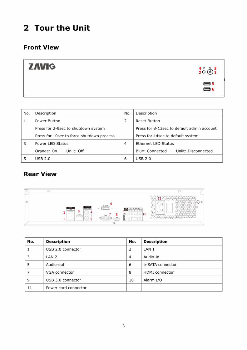
2 Tour the Unit
Front View
No. Description No. Description
1 Power Button
Press for 2-9sec to shutdown system
Press for 10sec to force shutdown process
2 Reset Button
Press for 8-13sec to default admin account
Press for 14sec to default system
3 Power LED Status
Orange: On Unlit: Off
4 Ethernet LED Status
Blue: Connected Unlit: Disconnected
5 USB 2.0 6 USB 2.0
Rear View
No. Description No. Description
1 USB 2.0 connector 2 LAN 1
3 LAN 2 4 Audio-in
5 Audio-out 6 e-SATA connector
7 VGA connector 8 HDMI connector
9 USB 3.0 connector 10 Alarm I/O
11 Power cord connector

4
3 Set up the Unit
3.1 Unpack the Unit and confirm it’s package contents
Item Qty Item Qty
9P-Terminal Block 3.81mm 2 Mouse 1
Red SATA cable 8 Rack-mount kit 2
Disk screws 32 Rack-mount screws 6
Power cord 1 Quick start guide 1
3.2 Install 3.5” HDD
Unscrew the housing on the back side.
Pull the cover.
Take out the HDD bracket from the
cabinet.
Loosen the screw on both sides of the
HDD bracket.

5
Screw the HDD onto the bracket. Reinsert the HDD bracket to the cabinet
Note: The connectors should face the
main board.
Screw the HDD bracket to the cabinet.
Connect the other red SATA cable
terminal and the power cable to each
connector.
Plug Red SATA cable the main board.
Screw the cover to the housing.

6
3.3 Connect the Unit and Devices within the Network
Connect the unit, cameras, and router/switch. If you need to make the video
visible over the Internet, please connect the router/switch to the Internet and the
unit will retrieve an IP address through DHCP by default.
The unit has built-in DHCP service, which can assign IP addresses; suitable for the
pure LAN environment.
3.4 Connect the Monitor
The unit has two display interfaces; connect the monitor via VGA or HDMI.
The supporting display resolutions are 1920x1080, 1280x1024, 1280x720, and
1024x768. Please confirm that one of the resolutions is supported by your monitor.
3.5 Power on
Connect the power cord directly to the back of the unit. See rear view figure.
Press the power button once the power cord is connected. See front view figure.
It takes about a minute for the unit to fully power up. Once it is powered up:
The System Status LED turns orange The buzzer beeps one time
If the system crashes or stops responding, press and hold the power button for 8
seconds to enforce hardware power-off, which turns off the computer by cutting off
the power directly. Such power-off isn’t recommended for a system that is working
properly.

7
4 First Power-on
To power on the unit, press the power button on the front panel. When the
system starts up for the first time, the user must select a language. The system
will restart again to apply the selected language.
Language can be changed later in Main Menu > System > System Settings > General
After restarting, the system will execute the Install Wizard, which will lead
users through the system’s basic settings configuration.
4.1 Install Wizard

8
Mode Description
Express Mode
Quick setup of the unit. Includes administrator password setup, online license activation, camera setup, and system date/time setting. Select this mode if you are not familiar with the network settings. Before proceeding with this mode, connect all the cables and cameras.
Advanced Mode
Complete set up of the unit. Includes all settings featured by Express mode with additional DHCP server settings, network settings, and RAID level settings.
All settings featured by Install Wizard are accessible on system’s Main Menu
1. Setup administrator password. To keep default password click Next.
2. The unit has built-in DHCP service, which enables the system to dynamically
assign IP addresses to the cameras within the same subnet.
If you have router in your
network, we recommend
choosing Always disable
to avoid any IP conflicts.
If you are not sure, please choose
Smart enable. The system will
automatically decide to enable or
disable the service depending on
your network environment.

9
3. If you select Smart enable, please set at least one LAN as a static IP.
4. Define the IP range for built-in DHCP server. The system will assign IP
addresses to the devices based on the range defined.

10
5. If you have POS license you may activate them now or click Next to proceed.
You may activate license later on the License Management menu.
6. Click Setup to search and automatically add the cameras within the same
subnet. Click Next to proceed.

11
7. Set up the time zone, date, and time, and adjust daylight saving changes if
needed. Once daylight saving function is enabled, the time change will
activate automatically every year based on the recurrence set.
8. Select the RAID type. If a volume has been created, the information will be
shown on the table as the picture below. Click Next to proceed.
The available RAID level depends on the amount of disks installed.

12
9. Review your settings. If the settings are correct, click the Finish button to exit
the settings procedure and activate the system.
Once the preliminary setup is through, the system automatically restart requiring
user to log in again. The default username and password are both “admin.”

13
5 User Interface
The operating system has two main screens, Live View and Playback screen.
The Live View screen shows the instant video(s) while the Playback screen
plays the recorded videos.
5.1 Live View
After users log in, the Live View window will show on screen. Live View is the
screen where live videos are displayed. Most of the Live View screen is occupied
by a video area, with a Status Bar spreading along the bottom of the screen.
Time Bar Toolbar
Video Area
Mode Icon
Status Bar
Playback
Video Area
Toolbar
Status Bar
Live View
Mode Icon Status Area
Stream Override

14
5.1.1 Video Area
If a camera is configured correctly, the Live View’s Video Area will show the
corresponding camera’s video feed.
Configure camera multi-stream icons on the Live View screen to override current
decoding streaming.
Two-way audio can be enabled on the Live View screen.
If a camera is not configured correctly, the Video Area of the Live View will
show a black screen having a “disconnection” icon in the center.
Video Area
Toolbar
Status Bar
Live View
Mode Icon Status Area
Stream Override
Stream Override
and Talk icon
Video Area
15
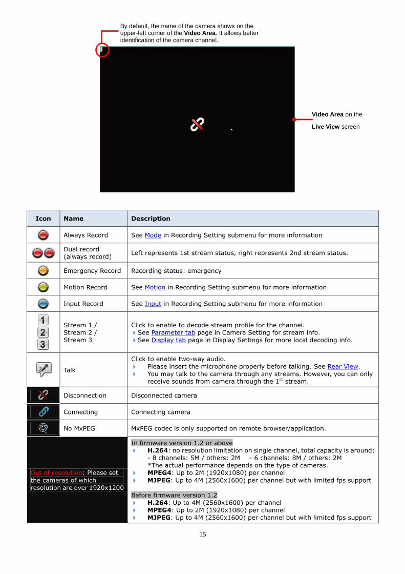
Icon Name Description
Always Record See Mode in Recording Setting submenu for more information
Dual record (always record)
Left represents 1st stream status, right represents 2nd stream status.
Emergency Record Recording status: emergency
Motion Record See Motion in Recording Setting submenu for more information
Input Record See Input in Recording Setting submenu for more information
Stream 1 / Stream 2 / Stream 3
Click to enable to decode stream profile for the channel. See Parameter tab page in Camera Setting for stream info. See Display tab page in Display Settings for more local decoding info.
Talk
Click to enable two-way audio.
Please insert the microphone properly before talking. See Rear View.
You may talk to the camera through any streams. However, you can only receive sounds from camera through the 1st stream.
Disconnection Disconnected camera
Connecting Connecting camera
No MxPEG MxPEG codec is only supported on remote browser/application.
Out of resolution: Please set
the cameras of which resolution are over 1920x1200
In firmware version 1.2 or above H.264: no resolution limitation on single channel, total capacity is around:
- 8 channels: 5M / others: 2M - 6 channels: 8M / others: 2M *The actual performance depends on the type of cameras.
MPEG4: Up to 2M (1920x1080) per channel
MJPEG: Up to 4M (2560x1600) per channel but with limited fps support Before firmware version 1.2 H.264: Up to 4M (2560x1600) per channel MPEG4: Up to 2M (1920x1080) per channel MJPEG: Up to 4M (2560x1600) per channel but with limited fps support
By default, the name of the camera shows on the upper-left corner of the Video Area. It allows better identification of the camera channel.
Video Area on the
Live View screen

16
To configure how to present the Video Area, see OSD.
To configure the Multi-stream parameter, see Parameter tab.
Double-click on a channel for full screen view. Double-click again to minimize.
5.1.2 Status Bar
The Live View’s Status Bar is divided into three sections:
5.1.2.1 Toolbar
The Toolbar on Live View screen has buttons for enabling system configuration.
Button Name Description
Playback Switches to Playback screen and opens the Search page to search for recorded videos by date & time.
Menu List
Opens a mini toolbar that covers the following buttons:
Button Description
Opens the Main Menu of the operating system.
Opens the I/O Panel, which lists the available I/O pins of I/O devices.
Triggers Auto Camera Setup, which searches and adds cameras to the system.
Logs out of the system.
Instant Playback Switches to Playback screen and replays an instant video. See
Playback to configure where to start replaying an instant video.
Layout Switches the screen layouts.
Auto Scan Triggers Auto Scan See Display for more details about Auto Scan.
Status Area Mode Icon
Status Bar
Toolbar

17
Group Manually switches the channels on the display screen.
Snapshot Opens a dialog to capture the screen of the selected channel or all channels on the screen. Click OK to save snapshot to a USB flash drive.
Digital PTZ Opens the digital pan/tilt/zoom panel to adjust camera view.
Physical PTZ Opens the physical PTZ control panel to adjust camera view. Available only when the camera supports PTZ.
Set Preset Point Set a point of view for the camera.
Go to Preset Point Jumps to a preset point or starts/stops patrol.
Emergency Record
Enables Always record. “Always record” means continuous recording.
See also Mode tab for details about the recording modes. See also Camera Status for details about the recording status.
Audio Opens a dialog to adjust audio volume or mute.
5.1.2.2 Status Area
The Status Bar shows the system date, time, IP address and so on.
To configure the information delivered by the Status Area, see Status Bar.
5.1.2.3 Mode Icon
In the left end of the Status Bar is a Mode Icon. It delivers the mode in which
the operating system is currently being used.
for Live View mode
for Playback mode
for Live View mode with new event(s) notification. Click on the icon to view
details of the event(s).
Server IP address System date & time

18
5.2 Playback
The Playback screen plays the recorded videos. The screen is occupied by a
video area, with a Status Bar spreading along the bottom of the screen.
5.2.1 Video Area
The screenshot below shows the Playback’s Video Area when recorded videos
are being played.
Video Area on the
Playback screen
Time Bar Toolbar
Video Area
Mode Icon
Status Bar
Playback

19
When selecting a period of time without any video recorded on the Playback’s
Video Area, a black screen is showed with nothing but a “no video” icon in
the center.
Icon Name Description
No video No video is being recorded at the moment.
No MxPEG MxPEG codec is only supported on remote browser/application.
Out of resolution:
Please set the cameras of which resolution are over 1920x1200
In firmware version 1.2 or above
H.264: no resolution limitation on single channel, the total capacity is around: - 8 channels: 5M / others: 2M - 6 channels: 8M / others: 2M *The actual performance depends on the type of cameras.
MPEG4: Up to 2M (1920x1080) per channel MJPEG: Up to 4M (2560x1600) per channel but with limited fps support Before firmware version 1.2
H.264: Up to 4M (2560x1600) per channel MPEG4: Up to 2M (1920x1080) per channel MJPEG: Up to 4M (2560x1600) per channel but with limited fps support
To configure how to present the Video Area, see OSD.
Double-click on a channel for full screen view. Double-click again to minimize.
2nd stream playback is not supported on local client.
H.265 Live view/ Playback is not supported local client.
Video Area
on Playback
screen
By default, the name of the camera shows in the
upper-left corner of the Video Area. It allows better
identification of the camera channel.

20
5.2.2 Status Bar
The Playback’s Status Bar is divided into three sections:
5.2.2.1 Toolbar
The buttons on Playback’s Toolbar controls the playback of a recorded video.
Button Name Description
Live View Switches to Live View screen.
Search Opens the Search page to search for recorded video by date or time.
Layout Switches the screen layouts.
Snapshot Captures the screen of the selected channel or all channels on the screen. Click OK to save the snapshot to the USB flash drive.
Play / Pause Starts or pauses the playing.
Stop
Stops playing. Playback stops by showing the frame where the video starts.
When video is fast-forwarded or reverse-played, Stop will restore the speed to x1.
Step Backward Hit this key once to bring the playback to the previous frame.
Step Forward Hit this key once to jump the playback to the next frame.
Previous Interval Hit this key once to bring the playback to the previous interval. See Playback to know how to set Playback Interval.
Next Interval Hit this key once to jump the playback to the next interval. See Playback to know how to set Playback Interval.
Rewind Hit once to rewind the videos with x-1 speed. Hit twice to rewind with x-2 speed. When rewind speed reaches x-16, it auto-restores to x-1 speed.
Fast Forward Hit once to fast-forward the playback with x2 speed. Hit twice to fast-forward the playback to x4 speed. When fast-forwarding speed is
incremented to x16, it auto-restores to x1 speed.
Digital PTZ Opens the digital pan/tilt/zoom panel to adjust camera view.
Audio Opens a dialog to adjust audio volume or mute.
Toolbar Time Bar Mode Icon
Status Bar

21
5.2.2.2 Time Bar
The Status Bar on the Playback screen shows the date and time of the video.
To configure the Status Area, see Status Bar.
5.2.2.3 Mode Icon
The Mode Icon on the Status Bar shows whether the operating system is
currently being used on Playback mode or Live View mode.
5.2.2.4 Search videos for Playback/Backup
To retrieve videos for playback or backup, click on the icon to open a time
table. Select the start time and click on the icon to show videos available in
the following 48 hours from the start time (shown as blue bar).
USB flash drive and portable hard disk device are both supported for video backup.
If you encounter problems when trying to backup on portable hard disk device,
please format the device with FAT32, NTFS is not supported currently.
The assigned date & time of videos

22
6 Settings
The operating system Main Menu features camera set up, recording and event
management, network configuration and other system settings.
To access the settings:
Open Live View screen. (See Live View)
Click the menu list button from the Status Bar.
Click Main Menu button .
Menu Button Summary
Camera
Search and add cameras within the same subnet. See Camera for the settings.
Recording & Event
Configures video recording schedule and sets the events. See Recording & Event for the settings.
Device
Manages camera input/output. See Device for the settings.
Storage
Manages the system’s storage and data backup. See Storage for the settings.
Network
Configures the systems’ networking. See Network for the settings.
Management
Manages users privilege, license activation, save/load configuration and check logs See Management for the settings.
System
Views system information, configures system settings, manages system upgrade, and run Install Wizard See System for the settings.
Display
Configures the system’s display. See Display for the settings.
Main Menu
Menu
submenus
23
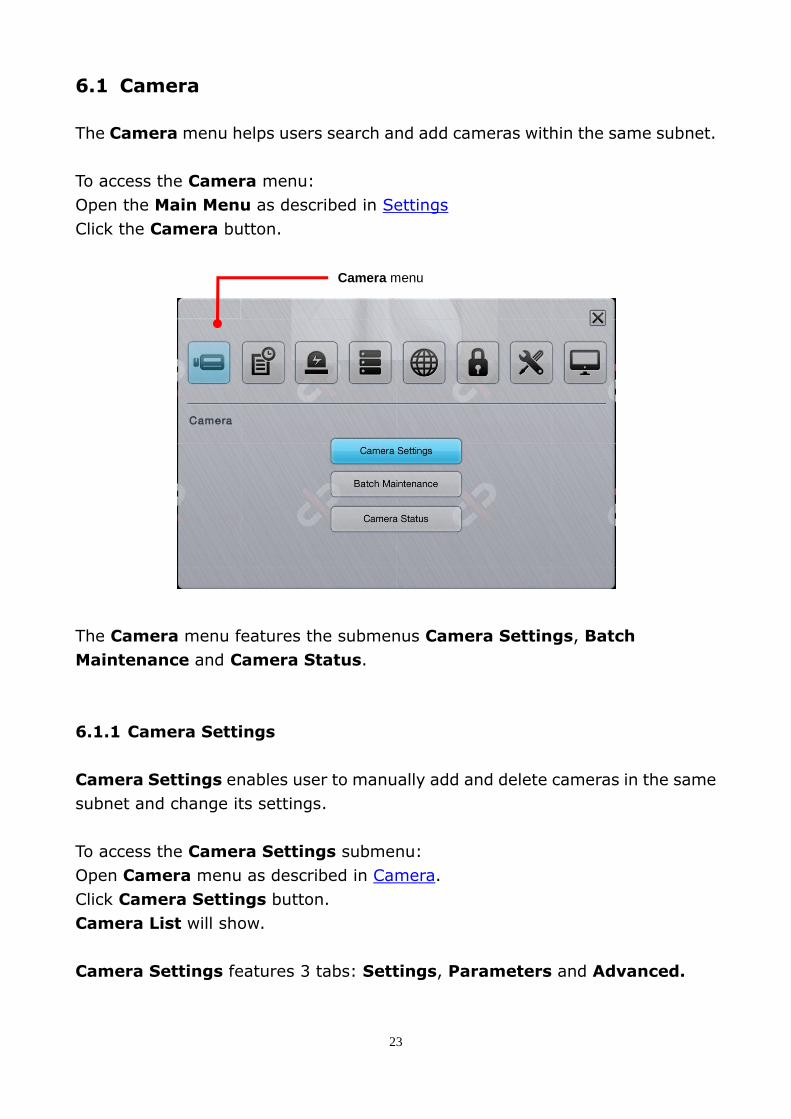
6.1 Camera
The Camera menu helps users search and add cameras within the same subnet.
To access the Camera menu:
Open the Main Menu as described in Settings
Click the Camera button.
The Camera menu features the submenus Camera Settings, Batch
Maintenance and Camera Status.
6.1.1 Camera Settings
Camera Settings enables user to manually add and delete cameras in the same
subnet and change its settings.
To access the Camera Settings submenu:
Open Camera menu as described in Camera.
Click Camera Settings button.
Camera List will show.
Camera Settings features 3 tabs: Settings, Parameters and Advanced.
Camera menu

24
6.1.1.1 Add Camera
To manually add cameras, follow the below steps:
Access Camera menu as described in Camera.
Click Camera Settings button.
Select Search icon on the upper left corner of the Camera list.
Choose the cameras you wish to add and click Add.

25
A window will pop up to fill in the camera’s information.
6.1.1.2 Delete Camera
To delete an existing camera, follow the below steps:
Access Camera menu as described in Camera.
Open Camera Settings submenu.
Select Settings icon on the upper left corner of the Camera list.
Choose the camera channel you wish to delete and click Clear.
Remember to click Save to apply the change.

26
6.1.1.3 Settings Tab
The Settings tab enables users to configure camera settings.
To access the Settings tab:
Open Camera menu as described in Camera.
Click Camera Settings button. Settings tab will display.
Press the refresh icon on the upper right corner to update the snapshot image.
On the Settings tab, the featured settings are:
Setting Description Default
Selects the camera channel to configure
Camera Type Defines whether the camera was added automatically or manually. Auto
Camera Name Set the camera name. --
IP Address Insert camera’s IP address. --
Port Insert port number. 80
Administrator Insert camera’s username and password. --
Password --
Protocol
Set the protocol for the camera. This setting is only available after Model setting is done. Options available are TCP, UDP and HTTP. However the option
availability depends on camera’s brand and model.
--
Model Select camera brand and model from the list or use Auto Detection. --
Channel
Set the number of analog cameras supported by one video server or sets
the number of IP cameras possessing multiple lens/channels.
This setting is only available after Model setting is done.
--
Click the keyboard icon at the right of the field to open the virtual keyboard for text input.
Camera
image
preview

27
6.1.1.4 Parameter tab
The Parameter tab configures how the camera records and how live videos are
played on Live View screen.
To access the Parameter tab:
Open Camera menu as described in Camera.
Click Camera Settings button.
Click Parameters tab.
Setting Description Default
Selects a camera channel to configure.
Multi-stream Enable/Disable camera multi-stream. Enable(Auto)
Stream Support up to three streams. --
Video Format
Sets the formats that the camera supports. Options available areH.264, MPEG4, MJPEG and MxPEG.
However option availability depends on camera’s brand and model.
Currently MxPEG decoding isn’t supported on local display. The MxPEG-decoded videos can only be viewed via web or remote browser.
--
Frame Rate Sets the frame rate of the camera. --
Resolution Sets the video resolution of the camera. --
Bit Rate Control Sets the bit rate control of the camera. --
Quality/Bit Rate Sets the video image quality of the camera. --
Audio Enables/disables viewing and recording videos with audio. --
Click the Save button to apply the change(s)
Click the Exit button to quit the tab.

28
6.1.1.5 Advanced
The Advanced menu allows user to set up Motion Detection, detection’s
Sensitivity, Interval and Detection Area.
Please note this defines the server’s motion detection, not camera’s motion detection. For camera’s motion detection, please access it directly via camera’s application or webpage.
Set up motion detection area
Select channel to apply motion detection, then use left click of the mouse to drag
and select the desired areas. To de-select areas, perform the same action with
the starting point on the selected area. Multiple detection areas can be created.
Click [Select All] to highlight entire view. Click [Clear All] to de-select all areas.

29
Sensitivity and Interval
Sensitivity: More darker bar levels means higher sensitivity. Setting up an
appropriate sensitivity will minimize false alarms triggered by swinging trees.
Interval: More darker bar levels means higher interval time so that the alarm
will be triggered when the movement lasts longer. Setting up an appropriate
interval will reduce the chance of false alarms triggered by pedestrians.
Simulation: Click the Simulation button to test the motion detection effect on
the preview screen. If motion is detected, “Event triggered” will show on screen.
Click Save to apply the new settings, then click Simulation to test the function.
6.1.1.4 IPC Motion
The IPC Motion allows user to set up motion detection on local client.
Set up motion detection area
Select channel to apply motion detection, then use left click of the mouse to drag
and select the desired areas. To de-select areas, perform the same action with
the starting point on the selected area. Multiple detection areas can be created.
Select Display All Range to show all the motion detection areas.
Click the virtual keyboard to change the name of the motion detection.
Click Add to create motion detection. Click Delete to delete motion detection.

30
Sensitivity and Threshold
Sensitivity: drag the button to increase or decrease the sensitivity so that alarm
will be triggered based on the level of movement.
Threshold: drag the button to increase or decrease the threshold so that the
alarm will only be triggered when the movement exceeds certain reaction.
6.1.2 Batch Maintenance
Batch Maintenance enables several functions that include Naming, Camera
firmware upgrade, Language pack upload, Reboot, Reset to default.
The search relies on UPnP. Before using this function, make sure your camera
supports UPnP.
To access the Batch Maintenance:
Open Camera menu as described in Camera.
Click Batch Maintenance button.

31
In Naming tab, camera image preview will appear for users to identify the
camera and name it by using the virtual keyboard.
In Maintenance tab, system enables user to upgrade camera firmware, upload
language pack and reboot, and reset camera to default setting.
To enable the maintenance features, user needs to select the camera first, and
then select the function to apply.
Function
button

32
6.1.3 Camera Status
Use Camera Status to monitor the camera connection status. It also allows
users to have an overview of the camera status and total bit rate.
To access the Camera Status submenu:
Open Camera menu as described in Camera.
Click Camera Status button.
The Camera Status menu features the submenus Camera Status and Details.
Camera menu

33
6.1.3.1 Camera status tab
The Camera Status tab shows camera connection status and total bit rate.
To access the Camera Status tab:
Open Camera menu as described in Camera
Click Camera Status button
Select Status tab
Camera Status delivers the info of each added camera including the following:
Item Description Status Info/Icon
No. Delivers the channel of the camera. --
Name Delivers the name of the camera. --
Recording
Status
Delivers the recording mode and recording
status.
No recording
Always recording – recording
Always recording – stopped
Always recording 2nd stream
Always recording 1st stream
Always recording – Dual record
Schedule recording – recording
Schedule recoding – stopped
Emergency recording – recording
Emergency recording – stopped
Frame Rate Delivers the frame rate of the camera. --
Bit Rate Delivers the transmission bit rate. --
Connection. Status
Delivers the camera’s connection status.
Disconnected.
Connected
Connecting…
Connects or disconnects a camera. Hit to connect
Hit to disconnect
6.1.3.2 Details tab
The Details tab shows camera streams status and total bit rate of the camera(s).
To access the Details tab:
Open Camera menu as described in Camera.
Click Camera Status button.
Select Details tab.

34
\
6.2 Recording & Event
Recording & Event helps users configure video recording and events to alarm.
To access the Recording & Event menu:
Open the Main Menu as described in Settings
Click Recording & Event button.
Recording & Event features Recording Settings, Event & Action, Email
and FTP Settings.
35
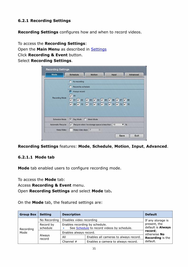
6.2.1 Recording Settings
Recording Settings configures how and when to record videos.
To access the Recording Settings:
Open the Main Menu as described in Settings
Click Recording & Event button.
Select Recording Settings.
Recording Settings features: Mode, Schedule, Motion, Input, Advanced.
6.2.1.1 Mode tab
Mode tab enabled users to configure recording mode.
To access the Mode tab:
Access Recording & Event menu.
Open Recording Settings and select Mode tab.
On the Mode tab, the featured settings are:
Group Box Setting Description Default
Recording Mode
No Recording Disables video recording If any storage is
present, the default is Always record; otherwise No
Recording is the default.
Record by schedule
Enables recording by schedule. See Schedule to record videos by schedule.
Always record
Enables always record.
All Enables all cameras to always record.
Channel # Enables a camera to always record.

36
Schedule
Mode
Day Mode Enable schedule recording by day or week.
For further schedule settings, see Schedule.
Selected
Week Mode Deselected
Automatic Recycle
Enable Enables automatic recycle when the storage space is less than a certain percentage.
Selected 10%
Keep Video Keep video days
Set how long to keep recorded videos (Max: 365 days) Deselected
The actual days of video kept depends on the available disk space.
6.2.1.2 Schedule tab
The Schedule tab sets the schedule to record videos.
To access the Schedule tab:
Access Recording & Event menu.
Open Recording Settings and select Schedule tab.
To change schedule from Day Mode to Week Mode, please go to Mode page.
The Schedule tab
set to Day Mode.
The Schedule tab set to Week Mode

37
On the Schedule tab, the featured settings are:
Setting Description
Selects a camera channel to configure.
Always record. Select and mark a time slot as “Always record”.
Motion record. Select and mark a time slot to record upon motion detection. This feature requires motion detection settings. See Motion .
Make sure the camera’s motion detection is enabled on camera web.
Input record. Select and mark a time slot to record upon digital input. This feature requires digital input detection setting. See Input tab.
Disable recording. Click to disable a time slot from recording.
In week mode, apply the schedule of the selected week day to another day or channel.
In day mode, apply the current day schedule to other channel(s).
6.2.1.3 Motion tab
Motion helps users set the pre- and post-recording time upon motion detection.
To access the Motion tab:
Access Recording & Event menu
Open Recording Settings and Select Motion tab
On the Motion tab, the featured settings are:
Setting Description Default
Select a camera channel to configure.
Pre-Record Set time to start recording right before the event of video motion occurred. 15 sec.
Post-Record Set time to keep recording after the video motion stops. 15 sec.
Camera Define which camera to start recording when channel’s motion is detected. --

38
6.2.1.4 Input tab
Input help users set pre and post-recording time upon triggering of digital input.
Setting Description Default
Select a camera channel to configure. (Channel 01)
Pre-Record Set the time to start recording before the digital input is triggered. 15 sec.
Post-Record Sets the time to keep recording after the digital input stops 15 sec.
Input Defines which camera to associate with the digital input. --
6.2.1.5 Advanced tab
Advanced tab enables watermark and dual recording settings.
Disabling watermark will save CPU loading, but unable to use verification tool.

39
6.2.2 Event & Action
To access the Event & Action submenu:
Open the Main Menu as described in Settings
Click Recording & Event.
Select Event & Action
Event & Action features: Camera, Camera I/O and System.
6.2.2.1 Camera
Camera enables settings for event & action from the camera.
To access the Camera tab:
Access Recording & Event
Open Event & Action and select Camera
Recording & Event menu

40
Setting Description Default
Select a camera channel to configure.
Motion from camera Enable the system’s action(s) when video motion is detected. If you wish to use motion detection by camera, please ensure the
camera’s video motion detection is enabled on camera web. Disabled
Connection lost Enable the system’s action when camera disconnection is detected. Disabled
Recurrent Enable the recurrent event. Disabled
Schedule button
Define a time period to keep the event & action active. When enabled, event (& action) is active from 00:00 through
23:59 by default. --
Action button
Output
When triggered, system will send output signal to connected devices. Once selected, a Detail dialog opens for users to set which output
pin to send the output signal through.
Disabled
When triggered, system will send Email notifications. To set up the Email(s) to receive notifications, see Email. Once selected, its Detail dialog opens for Email selection.
Disabled
Push notification
When triggered, system will send instant message to the registered
mobile clients as a notification. See Push Notification for details. Once selected, its Detail dialog opens for user selection.
Disabled
CMS When triggered, system will send out a signal to CMS. You may choose whether sending with snapshot or not.
Disabled
E-map
popup (remote)
When triggered, the system will pop up E-map with an event indicator
to show users the location of the scene clearly. Disabled
Snapshot to FTP
When an event occurs, the system will upload snapshots to FTP. Disabled
Details button
Output Opens a dialog for output pin selection.
See Device for detailed device I/O pin setting. --
Opens a dialog for Email selection.
See Email to set up the email(s) to receive notifications. You may choose whether sending Email with snapshot or not.
--
Push
notification
Opens a dialog for interval settings and user selection. See Push Notification for details.
See User Management to set up the user(s) to receive notifications.
--
CMS
Opens a dialog for CMS selection.
You may choose whether sending with snapshot or not. --
Snapshot to FTP
Opens a dialog for snapshot to FTP selection. You may configure how and when you want to stop sending. You may configure the frame interval.
--
PTZ preset
go
Opens a dialog for the PTZ preset go or patrol configuration You may configure how and when to Start PTZ preset point. You may configure the Life Cycle of PTZ.
The availability of event options depends on the camera’s feature.

41
6.2.2.2 Camera I/O
Camera I/O enables event & action for digital inputs/outputs detected through
one or more of the camera’s input pins.
To access the Camera I/O tab:
Access Recording & Event.
Open Event & Action and select Camera I/O tab
On the Camera I/O tabbed page, the featured settings are:
Setting Description Default
Selects a camera channel to configure.
Input#0 Enables the system’s action when an external input is detected through the camera’s input pin(s).
Disabled
Schedule button
Defines a time period to keep the event & action active. Once an event is enabled, the event (& action) is active from
00:00 through 23:59 by default. --
Action
Output
When an event occurs, the system will send an output signal to other connected devices. Once selected, a Detail dialog opens for users to set which
output pin to send the output signal through.
Disabled
When an event occurs, the system will send Email notifications. To set up the Email(s) to receive notifications, see Email. Once selected, its Detail dialog opens for Email selection.
Disabled
Push
notification
When an event occurs, the system will send instant message to the registered mobile clients as a notification. See Push Notification for details.
Once selected, its Detail dialog opens for user selection.
Disabled
CMS When an event occurs, the system will send out a signal to CMS. Disabled
E-map
popup
When an event occurs, the system will pop up E-map with an event
indicator to show users the location of the scene clearly. Disabled
42
Details button
Output Opens a dialog for output pin selection.
See Device for detailed device I/O pin setting. --
Email Opens a dialog for Email selection. See Email to set up the email(s) to receive notifications.
--
Push
notification
Opens a dialog for user selection. See Push Notification for details. See User Management to set up the user(s) to receive
notifications.
--
The availability of input pins depends on the camera’s feature.
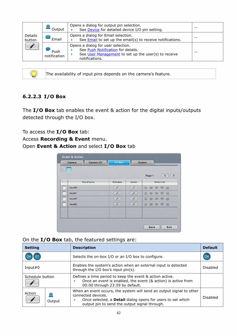
6.2.2.3 I/O Box
The I/O Box tab enables the event & action for the digital inputs/outputs
detected through the I/O box.
To access the I/O Box tab:
Access Recording & Event menu.
Open Event & Action and select I/O Box tab
On the I/O Box tab, the featured settings are:
Setting Description Default
Selects the on-box I/O or an I/O box to configure.
Input#0 Enables the system’s action when an external input is detected through the I/O box’s input pin(s).
Disabled
Schedule button
Defines a time period to keep the event & action active.
Once an event is enabled, the event (& action) is active from 00:00 through 23:59 by default.
Action
Output
When an event occurs, the system will send an output signal to other connected devices. Once selected, a Detail dialog opens for users to set which
output pin to send the output signal through.
Disabled

43
When an event occurs, the system will send Email notifications.
To set up the Email(s) to receive notifications, see Email.
Once selected, its Detail dialog opens for Email selection.
Disabled
push
notification
When an event occurs, the system will send instant message to the registered mobile clients as a notification.
See Push Notification for details. Once selected, its Detail dialog opens for user selection.
Disabled
CMS When an event occurs, the system will send out a signal to CMS. Disabled
E-map popup
When an event occurs, the system will pop up E-map with an event indicator to show users the location of the scene clearly.
Disabled
On
screen
display
When an event occurs, the system will show an alert message on selected camera(s) of screen.
Disabled
Details button
Output Opens a dialog for output pin selection. See Device for detailed device I/O pin setting.
--
Email Opens a dialog for Email selection.
See Email to set up the email(s) to receive notifications. --
push
notification
Opens a dialog for user selection. See Push Notification for details. See User Management to set up the user to receive notifications.
--
The availability of input pins of remote I/O box depends on models.
6.2.2.4 System
The System tab enables the event(s) & action(s) for some system abnormalities.
To access the System tab:
Access Recording & Event.
Open Event & Action and select System tab
44
On the System tab, the featured settings are:
Setting Description Default
Abnormal disk status Enables the system’s action when there is no enough disk space for recording or when disk accessing goes wrong.
Disabled
Daily system report Enables the system sending daily notification to one or more Email about the system’s HDD usage.
Disabled
Unable to access FTP Enables the system sending notification to one or more Emails
when system loses connection with FTP server for auto-backup. Disabled
Backup unfinished Enables the system sending notification to one or more Emails when the system cannot complete the process of auto-backup.
Disabled
Power-on notification Enables recording the time when the system is powered on after the power resumes from an abnormal shutdown.
Disabled
System overheating Enables sending notification to one or more Emails once the
system gets overheated and auto powers off. Disabled
Schedule button
Schedule is not available for system events. When enabled, the system event (& action) stays active from 00:00 through 23:59.
Action
Output
When an event occurs, the system will send an output signal to
other connected devices. Once selected, a Detail dialog opens for users to set which
output pin to send the output signal through.
Disabled
When an event occurs, the system will send Email notifications. To set up the Email(s) to receive notifications, see Email. Once selected, its Detail dialog opens for Email selection.
Disabled
push
notification
When an event occurs, the system will send instant message to the registered mobile clients as a notification.
See Push Notification for details. Once selected, its Detail dialog opens for user selection.
Disabled
CMS When an event occurs, the system will send out a signal to CMS. CMS will highlight this event.
Disabled
E-map
popup
When an event occurs, the system will pop up E-map with an event indicator to show users the location of the scene clearly.
Disabled
Details button
Output Opens a dialog for output pin selection. See Device for detailed device I/O pin setting.
--
Email Opens a dialog for Email selection. See Email to set up the email(s) to receive notifications.
--
push
notification
Opens a dialog for user selection.
See Push Notification for details.
See User Management to set up the user(s) to receive notifications.
--
6.2.2.5 Push Notification
When triggered, the system will send notification to the registered mobile clients.
To enable Push Notification as a responding action for an event:
Access Recording & Event.
Open Event & Action and Select Action Icon
An Action Management window will pop up.
Configure the rearm interval and assign user(s).

45
Setting Description Default
Rearm Interval
Define the minimum interval of notifications as the event occurs, to avoid receiving multiple notifications of the same event.
10 Sec. (Max: 300)
User List Shows all users configured in this unit. Select users to receive notification. See User Management to set up users.
Disabled
When an event occurs, the user will receive push notifications. The user can view
click “View” to watch the recording videos.
If user password is changed, please sign-in with new password to start service again.
Users can turn off push notifications on mobile client. If users logged into the mobile
client by typing NVR’s LAN IP and WAN IP, user must turn off this feature on both side.
Recipients of the notification can be changed in Event & Action Management page.
User account won’t be exported as saving configuration, which implies the user list of
push notification won’t be saved as well.

46
6.2.3 Email
The Email page sets up the recipients of the notifications sent by the system for
the configured events. It also manages the SMTP server for outgoing Emails.
To access the Email submenu:
Open Recording & Event.
Click Email
Email setting features: Contact and SMTP.
6.2.3.1 Contact
The Contact tab sets up the recipients of the notifications sent by the system.
The systems supports up to 40 contacts.

47
To access the Contact tab:
Open Recording & Event
Click Email
Select Contact
On the Contact tab, the featured settings are:
Setting Description Default
Name Set up an identity for the Email. --
Email Input the email address. --
Delete button Deletes the Email from the contact list. --
6.2.3.2 SMTP
SMTP sets up the “Simple Mail Transfer Protocol” for system to send out Emails.
To access the SMTP tab:
Open the Main Menu as described in Settings
Open Recording & Event
Click Email
Select SMTP
On the SMTP tab, the featured settings are:
Setting Description Default
Server address Enters the SMTP server’s IP address or server name. --
Port Assigns the port number. 25
Use SSL Enables/disables Secure Sockets Layer. Disabled

48
Sender Enters the sender’s Email address. --
Subject Defines a subject for all the Emails sent. --
Body Defines Email content. Press [ Shift + Enter ] to go to next line.
SMTP Authentication
Enables the username/password authentication before an Email is sent. Disabled
Username Sets up the username for SMTP authentication. --
Password Sets up the password for SMTP authentication. --
Test button System will send a test Email to sender to make sure the function works. --
6.2.4 FTP Settings
FTP Settings helps users set the FTP server to save backup data and snapshots.
To access the FTP Settings:
Open the Main Menu as described in Settings
Open Recording & Event.
Click FTP Settings

49
On the FTP Settings tab, the featured settings are:
Setting Description Default
FTP Server Sets the IP address or server name of the backup server. --
FTP Port Sets the port number of the backup server. 21
Username Enters the username to log in the backup server. --
Password Enters the password to log in the backup server. --
Folder
Specifies the folder to save the backup data to.
The folder name should be the format of “FolderName”, “FolderName/SubFolderName” and so on.
--
Test Runs a test on the configuration by making the system create a folder onto the
configured FTP server. --
6.3 Device
Device features the I/O Box Settings and I/O Pin Settings.
To access the Device menu:
Open the Main Menu as described in Settings
Click Device
6.3.1 I/O Box Settings
I/O Box Settings configures the I/O box to do the further input/output settings.
6.3.2 I/O Pin Settings
I/O Pin Settings manages input/output pins of cameras under same subnet.
I/O Pin Settings features: Camera I/O and I/O Box.

50
6.3.2.1 Camera I/O
Camera I/O tab manages the input pins and output pins of the cameras.
To access the Camera I/O tab:
Open Device from Main Menu
Click I/O Pin Settings
Select Camera I/O
On the Camera I/O tab, the featured settings are:
Setting Description Default
Selects a camera channel to configure.
I/O Pin Enables/disables an I/O pin. Enabled
Name Enters a name or info about the I/O pin. --
Type Sets I/O type for the I/O pin. N/O means normally open. N/C means normally close.
N/O (normally open)
Duration Defines the time to keep an output active after it is triggered.
N/A (The output stays active unless it is manually switched off.)
Associated Camera
Selects an associated camera for input pin, which will be the communication media for server and client. (e.g. when an input was triggered and pushed a notification to mobile, users can
playback the videos of its associated camera.)
Itself

51
6.3.2.2 I/O Box
The I/O Box tab manages the input pins and output pins of the I/O box.
To access the I/O Box tab:
Open Device from Main Menu
Click I/O Pin Settings
Select I/O Box
On the I/O Box tab, the featured settings are:
Setting Description Default
Selects the on-box I/O or an I/O box to configure.
I/O Pin Enables/disables an I/O pin. Enabled
Name Enters a name or info about the I/O pin. --
Type Sets I/O type for the I/O pin. N/O means normally open. N/C means normally close.
N/O (normally open)
Duration Defines the time to keep an output active after it is triggered. N/A (Output stays active unless it is manually switched off.)
Associated Camera
Selects an associated camera for input pin. N/A

52
6.4 Storage
Use the menu Storage to manage the system’s storage and data backup.
To access the Storage menu:
Open the Main Menu as described in Settings
Click Storage
The Storage menu features RAID Management and Auto Backup.
6.4.1 RAID Management
RAID Management manages the system’s RAID (Redundant Array of
Independent Disks), which combines multiple disk drives into a logical unit.
To access the RAID Management submenu:
Open Storage menu as described in Storage.
Click RAID Management.
RAID Management features: Status, Create, Modify, Delete and Format.
To avoid problems accessing public folder via My Network Places, please delete the
invalid volume before creating new disk volume or modifying volume.
If you choose Express Mode when using the Installation Wizard, the disk will be set
to RAID 0 automatically unless the number of disks is not enough for this RAID level.
Storage menu

53
To avoid any error on the HDD and RAID volume, the unit is not allowed to query
status, create, modify, delete, or format RAID volume when the front panel is open.
Disk hot swap on external storage is not supported. Please reboot the unit after the
installation.
6.4.1.1 Status
Status tab delivers the status of RAID “volume”.
To access the Status tab:
Open Storage menu as described in Storage.
Click RAID Management and select Status
On the Status tab, the featured settings are:
Setting Description Default
List Delivers the present RAID volume(s) in the system. --
Status Switches the status info between the present RAID volume(s) and disk(s).
If no RAID exist, “No Volume” will be displayed, otherwise default is “Volume 1”
The status info delivered for a present RAID volume is:
Info Description
RAID Name Delivers the name of the RAID volume, which is assigned when the volume is created.
RAID Level Delivers the RAID level, which is defined when the volume is created. The selectable levels depend on the number of drives present in the system.
See Create to know how to define the RAID level.

54
RAID Status
Delivers the following statuses of the RAID volume:
Message Description
Functional The RAID volume is normally operating.
Critical There are problems with the RAID volume, but video recording is normal.
Offline The RAID volume cannot be found. Hence video recording is stopped and the storage cannot be accessed.
File system error
The RAID volume is found but isn’t mounted. Hence video recording is stopped and storage cannot be accessed.
Free Capacity Delivers the free space on the RAID volume.
Used Capacity Delivers the used space on the RAID volume.
Usage Delivers the percentage of the RAID volume’s usage.
Update Time Delivers the time when the RAID volume was created or last updated.
Number of Devices
Delivers the total number of disks covered by the RAID volume and the number of the disks that are active, failed or spare.
Format Process Delivers the formatting progress if the RAID volume is being formatted at the moment.
Recovery Process
Delivers the recovery progress if the RAID volume is being recovered at the moment.
To run SMART Test, select disk and click the Test button.
Click the Stop Test button to stop the test.
Click the Drive Health (SMART) status to view the details of SMART result.

55
Info Description
Vendor Delivers the manufacturer of the disk.
Model Delivers the model number of the disk.
Capacity Delivers the total capacity of the disk.
Firmware Delivers the firmware version of the disk.
Serial No. Delivers the serial number of the disk.
RAID Status Delivers the status of the RAID that the disk belongs to.
Drive Health (SMART)
Delivers the status of drive health by SMART self-test. Click on icon to view the detail.
Good: The disk is healthy and able to work normally.
Warning: The disk is damaged. Recommend to change the disk.
Abnormal: The disk is damaged seriously and it may cause the system errors.
Strongly recommend you to stop recording and change the disk immediately.
Temperature Delivers the temperature of the disk.
Previous Test Time
Delivers the previous SMART self-test time.
SMART Status Check
SMART test progress. Recommend to stop recording to run the test. Short Test: 3-5 minutes. Extended Test: more than 300 minutes.
6.4.1.2 Create
The Create tab enables the creation of RAID volumes in the system.
To access the Create tab:
Open Storage menu as described in Storage.
Click RAID Management and select Create

56
On the Create tab, the featured settings are:
Setting Description Default
RAID Level Defines the RAID level. It depends on the number of drives.
Assigned Disk Disk # Selects a disk for RAID volume. Deselected
The RAID Volume will be functional on another unit if all disks of this volume are moved.
The RAID level and the number of disks in a volume cannot be changed after it is set.
Separate the embedded disk(s) from the external disk (DAS). You cannot create a single
volume with both embedded and external disks inside.
Top HDD tray (1, 2, 3, 4) and bottom tray (5, 6, 7, 8) cannot be created as 1 volume.
6.4.1.3 Modify
Modify enables the replacement broken hard drive.
To access the Modify tab:
Open Storage menu as described in Storage.
Click RAID Management and select Modify
Modify a RAID volume:
(1) Select the damaged disk to remove and click Remove
(2) Replace with new disk, and add it to the Modify tab.
This function isn’t applicable to RAID 0, which has no data protection mechanism.
Use this function to safely unplug the running HDD.
57
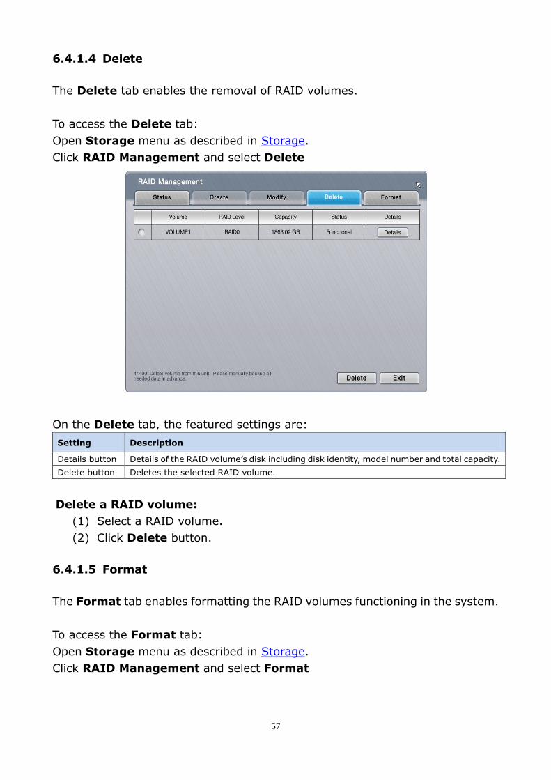
6.4.1.4 Delete
The Delete tab enables the removal of RAID volumes.
To access the Delete tab:
Open Storage menu as described in Storage.
Click RAID Management and select Delete
On the Delete tab, the featured settings are:
Setting Description
Details button Details of the RAID volume’s disk including disk identity, model number and total capacity.
Delete button Deletes the selected RAID volume.
Delete a RAID volume:
(1) Select a RAID volume.
(2) Click Delete button.
6.4.1.5 Format
The Format tab enables formatting the RAID volumes functioning in the system.
To access the Format tab:
Open Storage menu as described in Storage.
Click RAID Management and select Format
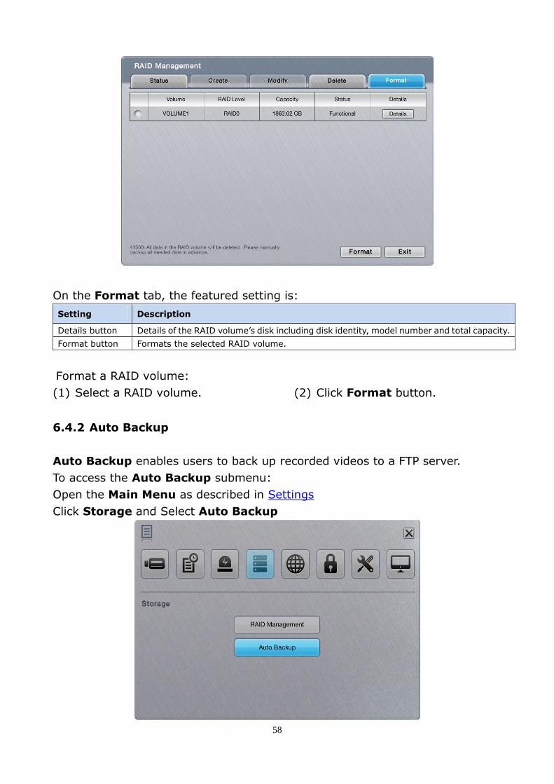
58
On the Format tab, the featured setting is:
Setting Description
Details button Details of the RAID volume’s disk including disk identity, model number and total capacity.
Format button Formats the selected RAID volume.
Format a RAID volume:
(1) Select a RAID volume. (2) Click Format button.
6.4.2 Auto Backup
Auto Backup enables users to back up recorded videos to a FTP server.
To access the Auto Backup submenu:
Open the Main Menu as described in Settings
Click Storage and Select Auto Backup

59
6.4.2.1 Schedule
The Schedule tab enables auto back up the recorded videos to a FTP server.
To access the Schedule tab:
Open the Main Menu as described in Settings
Click Storage
Select Auto Backup and choose Schedule tab.
On the Schedule tab, the featured settings are:
Setting Description Default
Auto Backup Enables auto back up of the videos recorded on the previous day. Disabled
Daily Backup Time Sets the daily time for the system to do the auto backup. 00:00
Video Start Time Sets the start time of recorded video of the previous day. 00:00
Video End Time Sets the end time of recorded video of the previous day. 00:00
Video Channels Sets the channel(s) to back up Deselected
6.5 Network
Network allows users to configure the systems’ network settings.
To access the Network menu:
Open the Main Menu as described in Settings
Click Network

60
Network features: Network Settings, Network Service and P2P settings.
6.5.1 Network Settings
Network Settings sets the system’s networking including IP address, subnet
mask, default gateway and primary/secondary DNS.
To access the Network Settings:
Open Network menu as described in Network.
Click Network Settings.

61
Network Settings features: Information, General, Setup and DDNS.
6.5.1.1 Information
Information allows users to view the system’s Ethernet networking settings.
To access the Information tab:
Open Network menu as described in Network.
Click Network Settings.
The Information tab will show.
Item Description
LAN 1 /
LAN 2
Shows the current network status of the two LAN ports. If a LAN port isn’t in use, the network status isn’t available. If a LAN port is in use, the following info are available:
Info Description
IP Address Delivers the IP address assigned to this LAN port.
Subnet Mask Delivers the subnet mask assigned to the IP address used on the LAN port.
Default Gateway Delivers the IP address assigned to the LAN port as gateway.
Primary/ Secondary DNS
Delivers the IP address assigned to the LAN port as primary or secondary DNS (Domain Name System).
To access the settings, see Setup.
Built-in
DHCP Server
Shows the system’s current “Built-in DHCP Server” status.
If the “Built-in DHCP Server” is enabled, the following info are available:
Info Description
Setting/Status Delivers the status of the “Built-in DHCP Server”.
IP Address Delivers the IP address assigned to the “Built-in DHCP Server”
To access the settings, see Setup

62
If all cameras are disconnected, please check if the network settings are
- LAN 1: static IP 192.168.1.100 (default) / not connected
- LAN 2: DHCP / connected to switch, which subnet is 192.168.1.X
or static IP 192.168.1.X / connected to switch, which subnet is 192.168.1.X
The system transmits package via LAN 1 in such condition. The solution is to change
LAN 1 settings to DHCP or connecting network cable on LAN 1.
6.5.1.2 General
General tab configures server name and selects LAN to connect to the Internet.
To access the General tab:
Open Network menu as described in Network.
Click Network Settings and select General tab.
The featured settings on the General tab are:
Setting Description Default
Server Name Name of unit for identifying server on email, push notification, etc. --
Internet Interface (WAN) Chooses the LAN connection for internet access. LAN 1
6.5.1.3 Setup
Setup configures system network, showing current LAN ports and its settings.
To access the Setup tab:
Open Network menu as described in Network.
Click Network Settings and select Set up tab.

63
The featured settings on the Setup tab are:
Setting Description Default
LAN 1/2 Type Assigns DHCP or static IP to the LAN port. DHCP (if skipped on Install Wizard)
Built-in DHCP
Type Enables/disables Built-in DHCP. When set to Smart enable, the system’s default static IP will
be shown on setting page if no static IP has been set up before.
Always disable (if skipped on
Install Wizard)
IP Address Assigns an IP address for the LAN port. This setting is only available when Type is set to Static.
192.168.1.100
Subnet Mask Assigns the subnet mask for the IP address of the LAN port. This setting is only available when Type is set to Static.
255.255.255.0
Default Gateway Assigns the IP address for the gateway for the LAN port. This setting is only available when Type is set to Static.
192.168.1.1
Primary DNS Assigns the IP address for the primary DNS. This setting is only available when Type is set to Static.
192.168.1.1
Secondary DNS Assigns the IP address for the secondary DNS.
This setting is only available when Type is set to Static. --
Starting IP Address
Sets the IP address for the built-in DHCP to start assigning from. 192.168.1.20
Ending IP Address
Sets the end of the IP address that the built-in DHCP assigns. 192.168.1.50
There are two Giga LANs per unit. We recommend using them as two subnets, one for the
devices, and the other for remote access. If you deploy two LANs within the same subnet,
it’s likely to cause device disconnection when either one of the LAN is disconnected.
6.5.1.4 DDNS
The DDNS tab enables/disables DDNS, which allows the system to use dynamic
IP address. This page also sets the DDNS profile.

64
To access the DDNS tab:
Open Network menu as described in Network.
Click Network Settings and select DDNS tab.
The featured settings on the DDNS tab are:
Setting Description Default
DDNS Enables/disables DDNS for the system Disabled
Provider Sets the provider of the DDNS service.
Options available are DynDns and DtDNS. DynDns
Username Set the username to login to the DDNS service. --
Password Set the password to login to the DDNS service. --
Host Name Enter the sub domain name. --
Update Cycle Set time period to refresh the DNS to pin point server’s IP address. 16 minutes
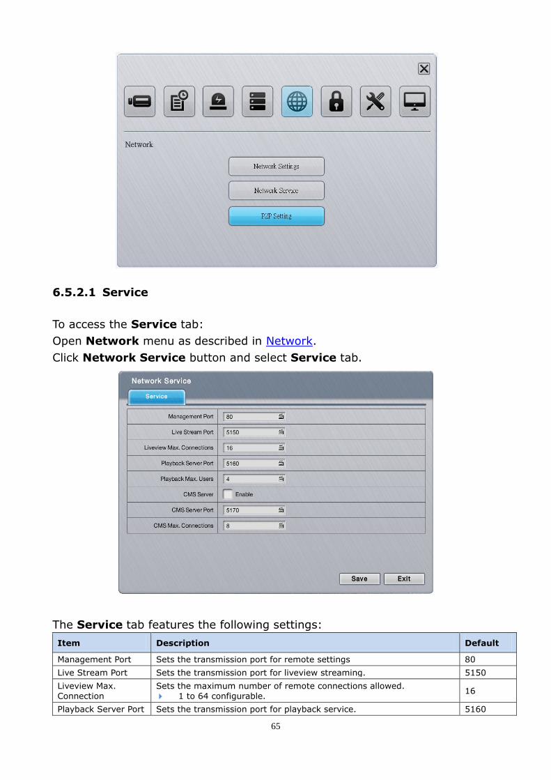
6.5.2 Network Service
Network Service controls remote access to liveview, playback, management.
To access the Network Service submenu:
Open Network menu as described in Network.
Click Network Service button.
65
6.5.2.1 Service
To access the Service tab:
Open Network menu as described in Network.
Click Network Service button and select Service tab.
The Service tab features the following settings:
Item Description Default
Management Port Sets the transmission port for remote settings 80
Live Stream Port Sets the transmission port for liveview streaming. 5150
Liveview Max. Connection
Sets the maximum number of remote connections allowed. 1 to 64 configurable.
16
Playback Server Port Sets the transmission port for playback service. 5160
66
Playback Max. Users
Sets the maximum number of users allowed to simultaneously access
the server for playback.
1 to 8 configurable.
4
CMS Server Enables/disables CMS service. Disabled
CMS Server Port Assigns the port number for CMS access. 5170
CMS Max. Connections
Sets the maximum number of CMS connections allowed. 1 to 8 configurable.
8
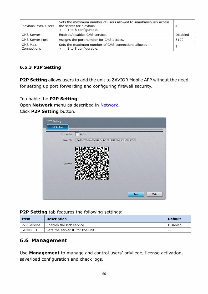
6.5.3 P2P Setting
P2P Setting allows users to add the unit to ZAVIOR Mobile APP without the need
for setting up port forwarding and configuring firewall security.
To enable the P2P Setting:
Open Network menu as described in Network.
Click P2P Setting button.
P2P Setting tab features the following settings:
Item Description Default
P2P Service Enables the P2P service. Disabled
Server ID Sets the server ID for the unit. --
6.6 Management
Use Management to manage and control users’ privilege, license activation,
save/load configuration and check logs.

67
To access the Management menu:
Open the Main Menu as described in Settings
Click Management.
Management features: User Management, License Management, Log
System and Save / Load Configuration.
6.6.1 User Management
User Management manages user accounts and access privilege to the system.
To access the User Management submenu:
Open the Main Menu as described in Settings
Click Management and select User Management.
User Management features: General, Channel Access, Local Privilege,
Remote Privilege, and Advanced.
68
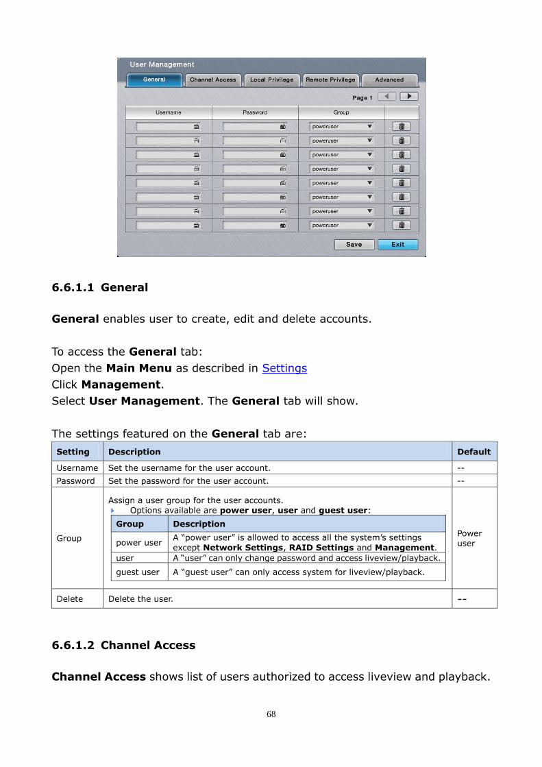
6.6.1.1 General
General enables user to create, edit and delete accounts.
To access the General tab:
Open the Main Menu as described in Settings
Click Management.
Select User Management. The General tab will show.
The settings featured on the General tab are:
Setting Description Default
Username Set the username for the user account. --
Password Set the password for the user account. --
Group
Assign a user group for the user accounts. Options available are power user, user and guest user:
Group Description
power user A “power user” is allowed to access all the system’s settings
except Network Settings, RAID Settings and Management.
user A “user” can only change password and access liveview/playback.
guest user A “guest user” can only access system for liveview/playback.
Power user
Delete Delete the user. --
6.6.1.2 Channel Access
Channel Access shows list of users authorized to access liveview and playback.

69
To access the General Access tab:
Open Management.
Click User Management and select Channel Access tab.
Click the edit button to edit a user’s access to a channel.
6.6.1.3 Local Privilege
Local Privilege tab shows the list of user(s) that are allowed to locally access
system services.
To access the Local Privilege tab:
Open Management.
Click User Management and select Local Privilege tab.

70
6.6.1.4 Remote Privilege
Remote Privilege shows users authorized to remotely access system services.
To access the Remote Privilege tab:
Open Management.
Click User Management and select Remote Privilege tab.
6.6.1.5 Advanced
Advanced tab shows list of users allowed to browse log.
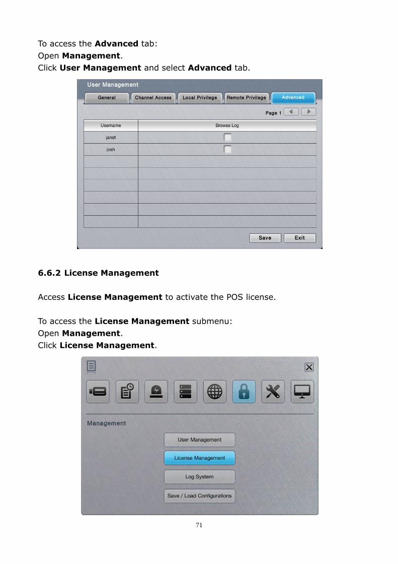
71
To access the Advanced tab:
Open Management.
Click User Management and select Advanced tab.
6.6.2 License Management
Access License Management to activate the POS license.
To access the License Management submenu:
Open Management.
Click License Management.

72
License Management features: Online Activation, Offline Activation and
Transfer.
6.6.2.1 Online Activation
Activate the license key (serial number) by following the steps below.
The system has to connect to the Internet by LAN1 port to run the online activation.
To access the Online Activation tab:
Open Management.
Click License Management. The Online Activation tab will open.
Upgrade the system with the available license key:
(1) Open the Online Activation tab as described above.
(2) Enter the serial number in the Input S/N field.
(3) Click the keyboard icon for text input.
(4) Click Activate button.
Once the activation succeeds, the license info displayed onscreen.
6.6.2.2 Offline Activation
If the system is without Internet connection, use the Offline Activation to
activate the license key.

73
To access the Offline Activation tab:
Open Management.
Click License Management and select Offline Activation tab.
Upgrade the system with the available license key:
(1) Have a USB flash drive. Plug it into any of the unit’s USB ports.
(2) Open Offline Activation tab as described above
(3) Click Export button and server file will be exported to USB flash drive.
(4) Copy the exported file “offline.reg” to a PC with Internet connection.
(5) Run “OfflineTool.exe”, which is included in NVR toolkit.
(6) Select Input SN file and enter the license key. Click Activate button.
(7) Save the offline license file “offline_license.dll” to the USB flash drive
(8) Plug the USB flash drive to one of the NVR’s USB ports.
(9) Reopen the Offline Activation tab.
(10) Click the Browse button and select the offline license file.
(11) Click the Import button to import the license file.
Once the activation succeeds, the license info displayed onscreen.

74
6.6.2.3 Transfer
There are two ways to transfer the activated license: online and offline.
To access the Transfer tab:
Open Management.
Click License Management and Select Transfer tab.
Transfer the activated license key online:
(1) Select the license from the License List, and click the Transfer button.
(2) The license will be removed from License List if transferred successfully.
Transfer the activated license key offline:
(1) Plug an USB flash drive into the unit’s USB port.
(2) Select the license from the License List, and click the Export button.
A dialog will pop on screen prompting the server file has been exported to
the USB flash drive. Click OK to close dialog. The license will be removed
from License List temporarily, but the transfer process is not finished yet.
(3) Copy the exported file “offline.reg” to a PC with Internet connection.
(4) Run the executable file “OfflineTool.exe”, which is included in NVR toolkit.
The Offline Tool opens.

75
(5) The license you are going to transfer is listed. Click the Transfer button
to finish the transfer process.
6.6.3 Log System
The Log System submenu allows users to view system events.
To access the Log System submenu:
Open Management menu as described in Management.
Click Log System button.
Log System features: System Log, Event Log, and Backup and Export.
Management menu

76
6.6.3.1 System Log
The System Log allows users to view the unit system operation history and
activities such as power-on, shutdown, and storage activity.
To access the System Log tab:
Open Management menu as described in Management.
Click Log System button.
System Log tab will show.
The featured settings are:
Setting Description Default
Switches the history to a specific range of time. To switch: 1. Click the down arrow of the date box and select a specific period of time. 2. Click the down arrow of the type box and select a type of log. 3. Click the Query button.
The current date
Click the right arrow button to view more logs. --
6.6.3.2 Event Log
Event Log allows users to view the history of the events from the configured
“Events & Actions”, such as video motion detection or camera connection loss.
See also Event & Action.

77
To access the Event Log tab:
Open Management menu as described in Management.
Click Log System button and select Event Log tab.
The featured settings are:
Setting Description Default
Switches the history to a specific range of time. To switch: 1. Click the down arrow of the date box and select a specific period of time. 2. Click the down arrow of the type box and select a type of log.
3. Click the Query button.
The current date
Click the right arrow button to view more logs. --
Click the link button to view the event playback. --
Click the event button to go back to view the event logs. --
The Event log is only recorded for the selected event(s) on the Event & Action submenu.
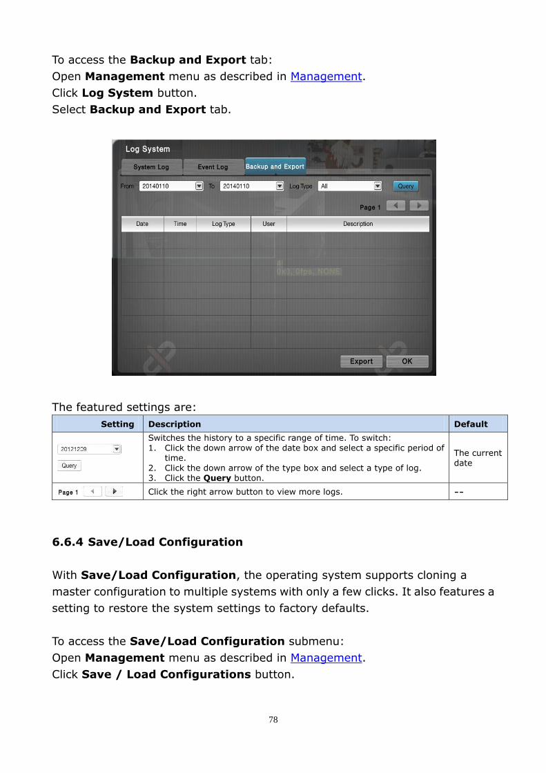
6.6.3.3 Backup and Export
The Backup and Export tab allows users to view the history of the system’s
exportation and backup of video files.
78
To access the Backup and Export tab:
Open Management menu as described in Management.
Click Log System button.
Select Backup and Export tab.
The featured settings are:
Setting Description Default
Switches the history to a specific range of time. To switch: 1. Click the down arrow of the date box and select a specific period of
time. 2. Click the down arrow of the type box and select a type of log. 3. Click the Query button.
The current date
Click the right arrow button to view more logs. --
6.6.4 Save/Load Configuration
With Save/Load Configuration, the operating system supports cloning a
master configuration to multiple systems with only a few clicks. It also features a
setting to restore the system settings to factory defaults.
To access the Save/Load Configuration submenu:
Open Management menu as described in Management.
Click Save / Load Configurations button.

79
Save/Load Configuration features: Save Config, Load Config and Reset.
6.6.4.1 Save Config
The Save Config tab saves the system settings to a configuration file.
To access the Save Config tab:
Open Management menu as described in Management.
Click Save / Load Configurations button.
The Save Config tab will open.
Management menu

80
The featured setting is:
Setting Description Default
Save Configuration Enters the name for the configuration file. “configuration”
Save the system’s settings to a configuration file.
(1) Plug a USB flash drive to one of the unit’s USB ports.
(2) Open Save Config tab as described above.
(3) Enter a name for the configuration file.
(4) Click the Save button.
The system will prompt configuration file is saved to the USB flash drive.
User accounts won’t be saved to the configuration file.
6.6.4.2 Load Config
The Load Config tab loads a configuration file for the system to apply.
To access the Load Config tab:
Open Management menu as described in Management.
Click Save / Load Configurations button.
Select Load Config tab.

81
The featured setting is:
Setting Description
Load Configuration Browses for the configuration file to load.
Load a configuration file for the system:
(1) Plug the USB flash drive containing the configuration file.
(2) Open Load Config tab as described above.
(3) Click the Browse and select the configuration file to load.
(4) Click the Load button.
The system will prompt the configuration file is loaded.
6.6.4.3 Reset
Use the Reset tab to restore all system settings to factory defaults.
To access the Reset tab:
Open Management menu as described in Management.
Click Save / Load Configurations button.
Select Reset tab.
The featured setting is:
Setting Description Default
Load Default Settings Restores the network settings to factory defaults. Deselected

82
Reset system settings to defaults:
(1) Open the Reset tab as described above.
(2) Select / deselect the Load network settings to defaults setting.
(3) Click Load button to load the defaults if you have selected Load
network settings to defaults in step (2). The system will proceed to load
the factory defaults and auto restart.
1. User accounts and privileges will be saved even after default settings are loaded.
2. RAID information will be saved even after default settings or configurations are
loaded.
6.7 System
Use the System menu to view system information, configure system settings
and manage system upgrade. It enables re-opening the Install Wizard.
To access the System menu:
Open the Main Menu as described in Settings.
Click System button.
The System menu features: Information, System Settings, System
Upgrade and Install Wizard.
System menu

83
6.7.1 Information
Information tab shows important system information including model,
firmware, CPU and heat dissipation.
To access the Information submenu:
Open System menu as described in System.
Click Information button.
Information tab will open
The information delivered is:
Info Description
Model Delivers the system’s model name.
Version Delivers the system version.
CPU Delivers the CPU model number.
MAC Address I Delivers the system’s MAC address.
MAC Address II Delivers the system’s MAC address.
CPU Temperature Delivers CPU temperature.
System Fan Speed Delivers system fan speed.
6.7.2 System Settings
System Settings allows users to configure and optimize the system.
To access the System Settings submenu:
Open System menu as described in System.
Click System Settings button.

84
System Settings features General, Playback, Date/Time, UPS, Shutdown.
6.7.2.1 General
General configures general system settings such as Main Menu timeout,
operating system’s language, security access and buzzer control.
To access the General tab:
Open System menu as described in System.
Click System Settings button.
The General tab will open.
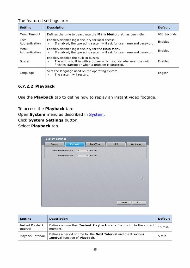
85
The featured settings are:
Setting Description Default
Menu Timeout Defines the time to deactivate the Main Menu that has been idle. 600 Seconds
Local Authentication
Enables/disables login security for local access. If enabled, the operating system will ask for username and password.
Enabled
Menu Authentication
Enables/disables login security for the Main Menu. If enabled, the operating system will ask for username and password.
Enabled
Buzzer Enables/disables the built-in buzzer. The unit is built in with a buzzer which sounds whenever the unit
finishes starting or when a problem is detected. Enabled
Language Sets the language used on the operating system.
The system will restart. English
6.7.2.2 Playback
Use the Playback tab to define how to replay an instant video footage.
To access the Playback tab:
Open System menu as described in System.
Click System Settings button.
Select Playback tab.
Setting Description Default
Instant Playback
Interval
Defines a time that Instant Playback starts from prior to the current
moment. 15 min.
Playback Interval Defines a period of time for the Next Interval and the Previous Interval function of Playback.
5 min.
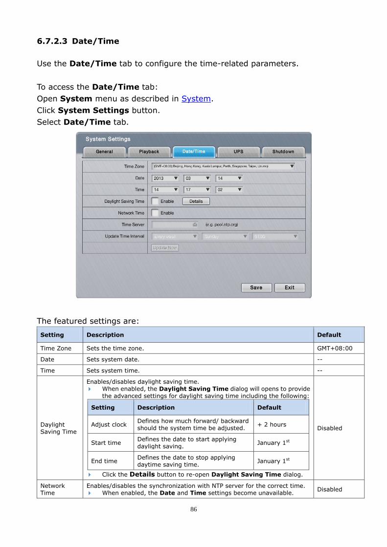
86
6.7.2.3 Date/Time
Use the Date/Time tab to configure the time-related parameters.
To access the Date/Time tab:
Open System menu as described in System.
Click System Settings button.
Select Date/Time tab.
The featured settings are:
Setting Description Default
Time Zone Sets the time zone. GMT+08:00
Date Sets system date. --
Time Sets system time. --
Daylight Saving Time
Enables/disables daylight saving time. When enabled, the Daylight Saving Time dialog will opens to provide
the advanced settings for daylight saving time including the following:
Setting Description Default
Adjust clock Defines how much forward/ backward should the system time be adjusted.
+ 2 hours
Start time Defines the date to start applying daylight saving.
January 1st
End time Defines the date to stop applying daytime saving time.
January 1st
Click the Details button to re-open Daylight Saving Time dialog.
Disabled
Network Time
Enables/disables the synchronization with NTP server for the correct time. When enabled, the Date and Time settings become unavailable.
Disabled

87
Time Server Sets the time server name or IP address.
This setting is only available when Network Time is enabled. --
Update Time Interval
Sets how often to synchronize the system with the time server.
This setting is available only when Network Time is enabled. Click the Update Now button to immediately update the system time.
Weekly on
Sunday, at 01:00 o’clock
The system will restart right after synchronization, meaning no video will be recorded
during this period. So choose the update interval carefully.
6.7.2.4 UPS
UPS configures how the system reacts to power failure by defining the timing for
auto shutdown. This tab also delivers the info about the UPS module used.
To access the UPS tab:
Open System menu as described in System.
Click System Settings button and select UPS tab.
The featured settings and delivered info are:
Group Setting Description Default
Power Failure Action
Disable Disable system’s actions to deal with power failure. Disabled
Shutdown when power is lower than _%
Sets how low does the UPS battery power drain down to before the operating system shuts down itself.
--
Shutdown when power
is lower than _ Min
Sets how long should the unit run on UPS battery power
before the operating system shuts down itself. --

88
UPS Info
Manufacturer Delivers the manufacturer of the UPS module. --
Product Name Delivers the product name of the UPS module. --
Serial Number Delivers the serial number of the UPS module. --
Services Status Delivers if the UPS module is servicing. --
The settings on the UPS tab are available only when an UPS module is connected.
For Power Failure Action, an USB connection is needed between the unit and the UPS
to check the status of UPS.
6.7.2.5 Shutdown
Use the Shutdown tab to safely turn off the unit or restart the operating system.
To access the Shutdown tab:
Open System menu as described in System.
Click System Settings button.
Select Shutdown tab.
Command Description
Reboot Stops all services and restarts the operating system. A dialog will open asking for confirmation. Click Yes to continue or click No to cancel.
Power off Stops all service and safely turn off the unit. A dialog will open asking for confirmation. Click Yes to continue or click No to cancel.

89
6.7.3 System Upgrade
Use System Upgrade to update system firmware.
To access the System Upgrade:
Open System menu as described in System.
Click System Upgrade button.
6.7.3.1 System Upgrade
System Upgrade tab enables system upgrade.
To access the System Upgrade tab:
Open System menu as described in System.
Click System Upgrade button. System Upgrade tab will open.

90
The featured facility and delivered info are:
Info / Facility Description
Current NVR Version Delivers current firmware version of the operating system.
Current Device Pack Version Delivers current device pack version.
Select File (Browse button) Browses for the firmware and runs the upgrade.
To upgrade the system follow below steps:
(1) Copy the firmware to an USB flash drive.
(2) Plug the USB flash drive to the system.
(3) Open the System Upgrade tab on the system as described above.
(4) Click the Browse button and select the firmware. Click OK button.
(5) Click the Upgrade button.
A dialog opens to ask for confirmation of the upgrade.
(6) Click Yes to confirm upgrade or click No to quit.
The system will restart automatically when the process is finished.
6.7.4 Install Wizard
Access the Install Wizard to reopen the Install Wizard.
To re-launch the Install Wizard:
Open System menu as described in System.
Click Install Wizard button.

91
The Install Wizard submenu opens and shows the Wizard tab.
Click the Start button to re-launch Install Wizard.
See Install Wizard for the follow-ups.
6.8 Display
Use the Display menu to configure the system’s display parameters, including
display layout, monitor resolution and other onscreen elements.
To access the Display menu:
Open the Main Menu as described in Settings
Click Display button.
Display menu

92
6.8.1 Monitor Settings
The Monitor Settings allows you to configure the system’s display parameters.
6.8.2 Display Settings
Display Settings configures the system’s display monitor, the presentation of
the onscreen Video Area, Status Bar.
To access the Display Settings submenu:
Open Display menu as described in Display.
Click Display Settings.

93
6.8.2.1 Display
Use the Display tab to configure how the videos are presented onscreen.
To access the Display tab:
Open Display menu as described in Display.
Click Display Settings.
Select Display tab.
In Secondary display, some features are limited.
The featured settings are:
Setting Description Default
Layout Sets the default layout for Live View display. 1x1
Auto Scan
Enables slide-showing multiple video channel(s) on the Live View screens.
When enabled, the seconds (dwell time) setting becomes available. Define the dwell time for each group of video to show on screen.
Disabled
Fix Aspect Ratio Enables fixing the ratio of video source instead of fitting it on every grid. Disabled
Efficient Local Display
Select “Auto” to save CPU loading by automatically applying low stream profile
on small grids. Select “Customize” to customize the stream profile manually. Also see Live View Video Area for stream override configuration.
Disabled
6.8.2.2 Camera Order
Use Camera Order tab change the order of video to show on Live View.
To access the Camera Order tab:
Access Display menu as described in Display.
Open Display Settings and select Camera Order tab.

94
Change the order of a video channel:
(1) Select a video channel. ( )
The selected channel becomes highlighted in blue color ( ).
(2) Click the left arrow key or right arrow key to advance or
withdraw the channel’s order among the available video channels.
6.8.2.3 Status Bar
Use the Status Bar to control the presentation of the Status Bar and the
information delivered by the Status Area. See also Status Bar.
To access the Status Bar tab:
Open Display menu as described in Display.
Click Display Settings and select Status bar tab.

95
The featured settings are:
Setting Description Default
Status Bar Sets how to show the Status Bar onscreen. Select Automatically hide to hide the Status Bar after 15 sec. idleness.
Always show
IP Address Enables Status Area to show the IP addresses of the systems and the cameras. Enabled
Date Enables Status Area and Time Bar to show system date. Enabled
Time Enables/disables the Status Area and Time Bar to/from showing system time. Enabled
6.8.2.4 OSD
Use the OSD tab to configure the system’s “on-screen” displaying.
To access the OSD tab:
Open Display menu as described in Display.
Click Display Settings.
Select OSD tab.
The featured settings are:
Setting Description Default
Camera Name
Enables showing the camera name in the upper-left corner of the Video Area. Click the Edit Style to change the font and style to show the camera name.
Enabled
POS Overlay
Enables POS transaction data on a played video. Select Live View to enable video with POS transaction data on Live View. Select Playback to enable video with POS transaction data on Playback. Click the Edit Style button to change the font and style of the displayed data. Go to web for more detailed settings about POS transaction data.
All enabled
POS Associated
Cameras
Enables/disables POS Overlay for a video channel. Go to web for more detailed settings about POS transaction data.
All enabled

96
6.8.2.5 Advanced
Use the Advanced tab to configure snapshot and event-pop up settings.
To access the Advanced tab:
Open Display menu as described in Display.
Click Display Settings.
Select Advanced tab.
The featured setting is:
Setting Description Default
Snapshot In addition to the 1x1 snapshot, it features another snapshot of the full
display layout including the status bar. Unchecked
Event Pop-up When event is triggered (motion detection and camera I/O only), local live view display the event camera as 1x1 layout. Pop-up time can be adjusted: Auto / 5 / 10 / 30 / 60 seconds.
Unchecked
If the length of your HDMI/VGA is over 1M, add a “repeater” to strengthen the signal.

Address: 2F. No.24-2, Gongye E. 4th Rd., East Dist., Hsinchu City 300, Taiwan
TEL: +886-3-579-0275
http://www.zavio.com