Embed Size (px)
Citation preview

SR940E 1/01 26.01.01
Version 1/01
ZANDER SR 940
Operating Manual
Content:
1. Toggles and switches 2
2. GPS flight page 3
3. Flight page without GPS 5
4. Info lines 6
5. Organisation of pages 7
6. Text pages 8
7. Configuration of SR940 17
8. Version 1/01: Changes compared to older versions
23
9. Electrical connections 23
10. Pressure ports 24
11. Compass and adjustment 25
12. Remote control 27
13. Data link to PC 28
14. Cable diagrams 29

SR940E 1/01 22.01.01 2
1. Toggles and switches:
Toggle +1 / -1: changes a value selected by the cursor by +1 and -1. Toggle Cursor down / up: moves the cursor one line down or up. Toggle Page forward / backwards: changes the total text on the display. Switch Variometer / Automatic / Speed command: sets the mode of the glider computer; the type of automatic is selected on text page „02: Configure“ Toggle combination +10 / -10 (toggles ±±±±1and Cursor moved together up or down): changes a value selected by the cursor by +10 and -10. Toggle combination Volume increase / decrease (toggles Cursor and Page moved together): changes the audio volume; must be set separately for variometer and speed command mode each. All toggles and toggle combination have repeating function. For example holding down the +1 toggle will increase the value selected by the cursor continuously by +1. Special functions: Toggle combination Reset (-R-): (toggles ±±±±1 and Page moved together downwards): resets the stop watch to 00:00, clears statistics and resets the leg number to zero; is used when departing. Toggle combination Stop Watch Halt: (toggles ±±±±1 and Page moved together upwards): halts stop watch and statistics; can be used when passing the finish line. Toggle combination Configuration Preset: (all three toggles together upwards): loads a complete set of configuration settings which were stored before by „02: Configure / 19=store configuration“ All toggles and the switch can be operated by remote control (see 12. Remote control).

SR940E 1/01 22.01.01 3
2. GPS Flight page: (with GPS installed) The flight page (page normally used during flight) is divided in three windows. The upper window has two lines of information which can be selected by line from a list of about 27 different informations (info lines). The middle window shows fixed information concerning soaring: MacCready seeting, climb rate averager, speed command information, wind component input for glidepath calculator, deviation from glidepath. The lower window shows GPS information: next waypoint name, distance and bearing to waypoint, selected route and leg, offset from course line (= cross track error), track over ground. For reasons of limited display area the heading error (difference between bearing and track) is shown in the right lower corner of the middle window. Where right/left information is involved, an arrow shows that direction which makes the diplayed number smaller. On the GPS flight page the distance used by the final glide computer is the GPS distance to the next selected waypoint. Before waypoints may be used, they have to be entered by hand, by IBM-PC or from GP940 into SR940 or may be copied from the internal airfield data base of SR940. If GPS reception is interrupted, the track over ground and heading error show dashes instead of numbers; after one minute without GPS reception, the GPS flight page is replaced by the flight page without GPS: the distance shows full kilometers only and the heading error disappears completely. The distance shown will now be counted down according to the airspeed. When GPS reception starts again, the GPS flight page will reappear after 10 seconds. „speed command“ mode:
info line 1: this: wind by force and direction info line 2: this: altimeter MSL MacCready setting, average netto, mini speed command director wind component setting, deviation from glidepath, heading error next waypoint, GPS distance and magnetic bearing to next waypoint task 3 / leg 1, GPS cross track error, track over ground (magnetic)
„variometer“ mode:
MacCready setting, average climb, sign for „variometer“ mode If the cursor is set to the last position (lower line, right side), the display of this line can be changed similar to the upper info lines. With +1 the display changes to the wind display (force and direction; direction is absolute during „variometer mode“ and relative during „speed
command“). If the page switch is held up for about two seconds, there will be a one time wind transfer from measured wind to the wind component W for glidepath calculator. If one of the info lines shows „remaining distance“, the average wind for all remaining legs until the last point is calculated and transfered to W (approach around one ore more corners). Wind transfer to glidepath calculator can also be continuously (only with compass option). Continuous wind transfer is started by holding up the page switch for 3.5 seconds; the letter „W“ changes to „w“. Continuous mode will stop when an entry at „w“ is done by hand or by an one time wind transfer. The advantage of the continuous mode is visible when flying near an outlanding field or near the home airfield, where the bearing to the waypoint is changing. In this case the glidepath calculator uses always the wind in direction to the landing point even when flying away from it. But due to the fact, that wind calculation is changing with time, the glidepath deviation is changing too and gained or lost height is no longer recognizable. So for final glide, where bearing does not change too much, the one time wind transfer is recommended to get full use of the TE compensated, high performance glidepath calculator. Continuous wind transfer uses the compass wind averaged over 2 minutes. Wind measurement by direction and force is done while circling or when in straight flight. When circling, the GPS ground speed is compared to the airspeed for a complete circle. In straight flight GPS ground speed and track is compared with airspeed and compass heading. For straight flight wind measurement the compass option is required. Wind measurement while circling needs a high quality GPS receiver (like flight data recorder ZANDER GP940). The first result is available after a complete circle of 360°, then the update is every second. The circle must not take longer than 60 seconds for 360°, the GPS must not stop during circling. The wind shown is the drift of the thermal, which is not always equal to the real wind. Recentering does not influence this wind calculation.
Wi:> 012kmh 342° Alt1: 1245m MSL 1.5mc +0.6n ^2 +09W -2316m ←←←←16° TANNH 089.2 127° 3/01 ←←←←07.3 143°
1.5mc +2.3M VA
3/01 >12kmh 342°

SR940E 1/01 22.01.01 4
For straight flight wind measurement an acurate deviation table must be entered into SR940 before. After about 20 seconds of quiet straight flight the wind information gets stable and usable. Straight flight wind shows the flow of the air which is very important when flying in mountain areas, but even in flat country the wind changes when approaching a thermal or cloud may often be very helpful. In straight flight without compass, only the wind component in direction of flight is measured. In this case wind transfer is only usable if the heading of the glider is towards the airfield. Actions on this page: (Page forward: toggle down; Page backwards: toggle up) change info lines
cursor on info line 1 or 2, toggle +1/-1
explain info lines
cursor on info line 1 or 2, toggle Page forward
change MacCready setting
cursor on mc, toggles +1 / -1 or +10 / -10
change glidepath wind component W
cursor on W, toggles +1 / -1 or +10 / -10 (tailwind = +)
advance to next leg
cursor on leg number, toggle +1
set buoy (store position)
cursor on waypoint name, toggle +1
store buoy permanently
cursor on *BUOY, toggle Page forward, toggle +1 = YES
restore previous waypoint
cursor on waypoint name, toggle -1
check and adjust important settings before takeoff
cursor on mc, toggle Page forward
set safety hight for glidepath calculator
cursor on deviation from glidepath, toggle Page forward
show waypoint information of next waypoint
cursor on waypoint name, toggle Page forward
show or change active route
cursor on leg numer, toggle Page forward
move cursor quickly to mc
hold up toggle Page backwards for 0.5 seconds
transfer GPS wind to W (one time transfer)
hold up toggle Page backwards for 2 seconds
transfer compass wind to w (continuous transfer)
hold up toggle Page backwards for 3.5 seconds (stop continuous mode with direct entry at w)
departure toggles Reset (-R-) down to reset the stop watch and set leg no.01 (=departure point)
after departure
cursor on leg number, toggle +1 to load leg no. 02 (= first leg)
arrival
if seconds are important: toggles -R- up

SR940E 1/01 22.01.01 5
3. Flight page without GPS: (no GPS installed) The D computer (D = distance) counts down a distance relative to airspeed when in speed command mode. Wind component is also used for distance calculation (in both variometer mode and speed command mode). The distance is initially set when beginning a new leg or is readjusted at a known positions by hand. The legs can be defined by waypoints (as for GPS) or can be entered directly (route 9: distances and direction for each leg). Directions of course lines are shown for information only and are not used for calculations. At the turnpoints the leg number shown on the flight page is advanced by toggle switch; by this action the next distance is loaded into the distance calculator. While the distance calculator is used for navigation the leg number on the flight page must not be changed. To calculate a wind component the distance D is set at a known position. After some time the remaining distance shown can be readjusted by the wind component setting to make shown distance and actual distance equal. „speed command“ mode:
info line 1: this selection: time, stop watch info line 2: this selection: altimeter MSL MacCready setting, average netto, mini speed command director wind component input, deviation from glidepath waypoint name, distance counter, direction of course line task 3 / leg 1, total distance since departure
„variometer“ mode:
MacCready setting, average climb, sign for „variometer“ mode
waypoints not used:
Actions on this page: (Page forward: toggle down; Page backwards: toggle up) change info line: cursor on info line 1 or 2, toggle +1 / -1 explanations to info line: cursor on info line 1 or 2, toggle Page forward change MacCready setting: cursor on mc, toggle +1/-1 or +10/-10 change wind component: cursor on W, toggle +1/-1 or +10/-10 change distance D: cursor on D, toggle +1/-1 or +10/-10 (wind calculation is started) transfer the next leg distance to D at the turnpoint
cursor on leg number, toggle +1 (wind calculation is started)
check and adjust important settings before takeoff:
cursor on mc, toggle Page forward
set safety height for glidepath calculator:
cursor on deviation from glidepath, toggle Page forward
show information of next waypoint:
cursor on waypoint name, toggle Page forward
show or change active route: cursor on leg number, toggle Page forward move cursor quickly to mc: hold up toggle page backwards for 0.5 seconds departure: toggles Reset (-R-) to reset the stop watch and statistics after departure: cursor on leg number, toggle +1 to advance to the first leg prepare wind calculation: set D at a known position, then wait for 5 minutes at the least do wind calculation: change W until D shows the actual distance
14:28:53 03:21 Alt1: 1245m MSL 1.5mc +0.6n ^2 +09W -2316m TANNH 089km 132° 3/01 0316km tot.
1.5mc +2.3M VA
----- 089km 132° 9/01 0316km tot.

SR940E 1/01 22.01.01 6
4. Info lines: Each of both upper two lines of the flight page can show different items selected from a list of info lines. To change the info lines set the cursor on first or second line of the flight page and use +1 / -1 toggle to step through all available informations. Some info lines are usable only if the appropriate option like GPS, compass or accelerometer is installed. Alt1: 1245m MSL altitude in meters MSL (=QNH) Alt2: 0905m GND altitude in meters GND (=QFE) Alt3 04082 ftMSL altitude in feet MSL Alt4 02967 ftGND altitude in feet GND Alt5 04212 ft FL altitude shown as flight level (as for 1010hp setting) 14:28:53 03:21 time, stop watch mc=0: +0375m glidepath deviation for MacCready = 0 (wind included) Rem.Dist. 0373km remainig distance from present position
(used as distance for final glide computer if selected for display) Wi:> 342° 012kmh Wi:* 356° 008kmh
GPS wind (direction from, speed) (> = wind update straight flight, * = wind update while circling
342°>12kmh ←←←←161° 342°*08kmh ←←←←021°
GPS wind (direction from, speed, direction relative to glider; left arrow shows: wind coming from left side )
Wcomp:> +12kmh GPS wind component C:>+012 S:>+003 GPS wind component C and crosswind (drift) S 196°*+0.5M ←←←←012° centering aid: absolute direction of recommended correction,
possible gain, relative direction (with audio signal when passing 000°)
Vgps: 094kmh GPS ground speed Vr: 078kmh travel speed 1245m 04082f 078 altitudes MSL, travel speed Vmc: 153kmh optimum speed (function of MacCready setting and polar curve) L/D avg.: 41 measured average L/D (time constant 15 sec.) M tot: +1.3m/s total average climb since last change from „cruise“ to „climb“ Temp: +24.9°C outside air temperature pTemp: +19.8°C potential temperature Flap: -1 optimum flap position (only with accelerometer) Test: 00000 content of test address (address selected on text page 24) →→→→→→→→→→→→0 graphical representation of heading error BLAUB 02.5 249° BLAUB 02.5 →→→→093°
nearest airfield (distance and direction) absolute direction in VARIO mode, relative dir. in SC mode
*P006 07.8 224° *P006 07.8 ←←←←068°
nearest Position absolute direction in VARIO mode, relative dir. in SC mode
DMUEN 13.9 275° DMUEN 13.9 ←←←←146°
nearest airspace (distance and direction) absolute direction in VARIO mode, relative direction in SC mode
PhotoSec2: →→→→043° photo sector type and photo angle (in sector: 0°...45°) arrow shows to bisector line
True Brg. 266.3° True bearing to waypoint

SR940E 1/01 22.01.01 7
Some explanations to info lines: The difference between altimeter MSL and GND is determined by field elevation on text page „05: Settings“. If FL altitude Alt5 should be used: before takeoff on text page „05: Settings“ QNH must be set first and then the altimeter is set to field elevation. In flight Alt5 shows an altitude as if the altimeter is set to standard setting 1013hp. The stopwatch is cleared with toggles -R- (=Reset); counts only in flight. This stopwatch is independent of stopwatch 2 on text page 07. Glidepath information mc=0 shows the safety margin during final glide. The same wind component is used for both glidepath calculator and this info line. If Remaining Distance is selected for one of the info lines, the glidepath calculator uses this distance. If wind with direction and force is transfered to W, an average wind for all remaining legs up to the last point is calculated and transfered to W. This is the same for continuous wind transfer. If measurement of wind with direction and force is interrupted (no update), a wind is shown as measured 10 seconds before the end of update. This avoids larger deviations which are normal when updating ends. The centering aid for thermalling shows the direction of a recommended correction, the possible gain in that direction and a relative direction. This works only while circling, first information is available after 360° turn, then every second until circling stops. Circle time must be less than 60 seconds for 360°, turning sense must be the same for the complete circle, the GPS must be of high quality, must be fast and must not stop during circling. The relative direction shows 000°, when the glider is heading in direction of the better part of the thermal. So the relative direction goes through 000° already 90° before the best climb rate is achieved. An audio signal can be turned on (see „02: Configure / 14= Centering), which gives one beep when going through 000°. To compensate for delays, a lead time can be set (0...9 seconds); also a minimum gain level can be set to avoid the audio signal for low gains. GPS ground speed is a „true“ speed. If you want to compare this speed to airspeed, you have to use „true airspeed (TAS)“. TAS can only be seen on the test page at address 204 (in km/h) and, after selection on the test page, also on the test info line. Travel speed Vr takes into account the difference between initial and momentary altitude. The difference is converted into time by using the average climb rate since initialization. So the indicated travel speed goes up when circling in a thermal which is stronger than average but goes down in a weaker thermal. Initialization is done when switching turnpoints. The arrow at Photo Sector angle always shows to the center of the photo sector. True bearing shows to the waypoint selected and shown on the flight page. On the right side of line 5 there is also shown a bearing. This bearing is magnetic and shows only full degrees. True bearing is used for AAT (Area Asigned Tasks), where boundary lines are given as bearings to a reference point. To be able to determine these boundaries with sufficient acuracy in flight, true bearing with one tenth degree of resolution is necessary. One degree of error may result in a position uncertainty of 1km at 50km distance to the reference point. As magnetic deviation calculated by the GPS receiver may differ from one system to another, magnetic bearing cannot be used for definition of boundary lines for AAT.

SR940E 1/01 22.01.01 8
5. Organisation of pages: With the toggle switch page advance other pages (screens) can be selected to replace the flight page. On each page different items (=„text pages“) can be shown. On page 0 (first page behind the flight page) however the item is predetermined by the cursor position on the flight page): flight page: page 0: Cursor on mc settings before takeoff = „05 Settings“ Cursor on waypoint name waypoint list = „10 WP list“ Cursor on route/leg route setup = „11 Route“ The following pages (= free pages) can be preprogrammed to show one of the available text pages. Text page „02: Configure / 18=free pages“ is used to set up page organisation. The number of free pages is selected first (1...9). If the number of pages is set to two or more, each page can be assigned a text number. Example: if number of pages is set to 3, then the first page may be set to 13 (= nearest airfields), the second to 17 (= airspace) and the third to 26 (= turnpoint graphics). If the number of pages is only one, a special function is active: page 1 always memorizes the text which was selected last on this page. The text on each page can be changed by changing the text number in the upper line. But when switched to one of the pages again, the preprogrammed text will show up. Return to flight page is done by using the page backwards toggle; it can be programmed if the return to the flight page goes directly with one stroke from all pages or going through page by page.
6. Text pages: LCD contrast adjustment (contrast 0...10); when power is turned on, the contrast is limited from 2 to 8. Contrast can be changed right after power is turned on, or later by selecting this text page; normally there is no adjustment necessary. Also on this text page: information about valid manual and actual program version. Change of configuration of SR940. Cursor in third line: select item Cursor in last line: select option All selected options stay in memory even if power for SR940 is turned off.
01: Contrast =05 ZANDER SR 940 Ser/Num: 198121 Manual: 01/01 Version: E2004
02: Configure 01= Units: VA: H: D: W: 1= m/s m km kmh
Before first use: Set all options according to chapter 8. Configuration of SR940
page 0
page 1
flight page
0)05 Settings
1)19 Statistics
mc
programable: more pages 2...9

SR940E 1/01 22.01.01 9
Explanations for info lines 1 and 2: Selection of info lines for the flight page can be done on these text pages too by changing the number on the second line; for each info line there is a short description. Pre Flight Settings: wing loading, best L/D (= Glide ratio), barometric pressure, altimeter of SR940 (A/SR9, altimeter of GP940 (A/GP), field elevation. „best L/D“ and wing loading determine the actual polar curve; dirty wings (bugs, rain) are taken care of by a lower „best L/D“ setting. In order to get correct readings for Flight Level altitude (info line Alt5) and altitude information on the airspace text page 17 and for altitude alarm, the QNH must be set before takeoff. Field elevation in feet: first cursor position changes in 100m steps, second cursor position changes in 1m steps; use +-10 for larger changes. The result is shown in feet.
Selection of altimeter: If a logger GP940 / version 1.25 is connected, the altimeter source for all altimeter displays (except glidepath) can be selected between SR940 altimeter or GP940 altimeter. The altimeter last set is marked by an angle and this angle shows, which altimeter source is used. GP altitude can only be used if the GP940 is turned on. The Glidepath normally ends at the surface of the next waypoint. If the next waypoint has no elevation information (elevation for this waypoint is zero in the waypoint list), then the field elevation of the home airfield is used instead (as set on text page 5 „Settings“). The end point of the glidepath can be lifted above the surface by adding some safety height. However, it is not recommended to enter any safety height to the glidepath; the deviation from glidepath (as shown on the flight page) should be regarded as „arrival height above ground“ and should include the necessary safety margin. This margin can be changed easily in flight by change of MacCready setting if necessary (large distance = larger margin, small distance = lower magin by increasing MacCready input). The Stopwatch 2 is automatically started at takeoff, but can be restarted manually by using the reset toggles or is restarted automatically by GPS when crossing the start line with leg 01 (=departure point) selected. The latest event of these determines departure time. The stopwatch is stopped, when crossing the finish line with GPS and finish point selected, or can be stopped manuallu by pushing both reset toggles upwards, or will be stopped automatically after landing. The earliest event will set the arrival time. When the stopwatch is stopped, the achieved speed for the total distance is shown. The total distance is the sum of all legs from departure point up to the last point of the route. The type of events are also noted: „F“=flight (takeoff and landing), „R“=Reset switches, „S“=Stop switches, „G“=GPS.
03:Selection 1 07= Wi:> 342° 012kmh Wind (from direction,speed)
04:Selection 2 01= Alt1: 1245m MSL altitude m mean sea level
05: Settings weight =38kpm² best L/D =45 QNH =1021hp A/SR= 00341mMSL >A/GP= 00341mMSL A/Fld. =0341mMSL
Before takeoff: turn on GP940 first set QNH then set A/SR to field elevation (used by glidepath calculator) then set A/GP to field elevation now SR940 and GP940 may be turned off again
06: Glidepath ends: 0591m MSL = TANNHAUSEN 0491m MSL + safety height =100m
07: Stopwatch 2 dep: G 08:23:51 arr: G 14:53:51 dur: 06:30:00 077.6kmh total: 0504.2km
SR940E 1/01 22.01.01 10
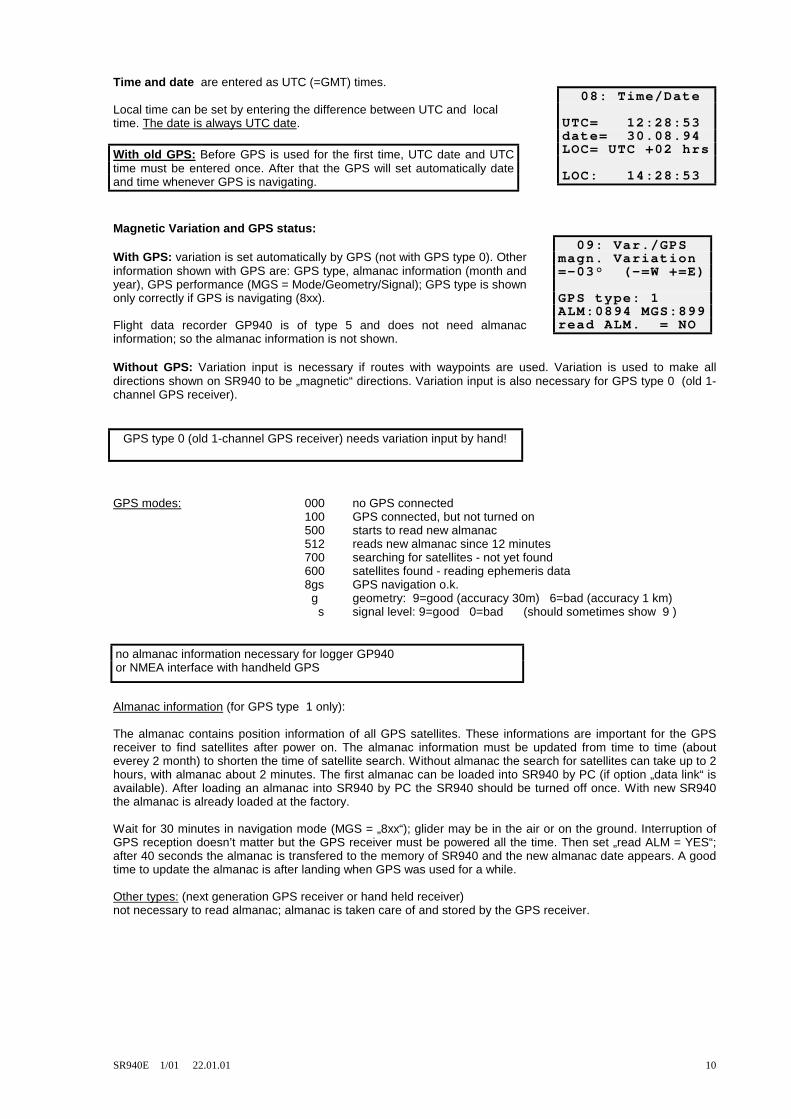
Time and date are entered as UTC (=GMT) times. Local time can be set by entering the difference between UTC and local time. The date is always UTC date.
Magnetic Variation and GPS status: With GPS: variation is set automatically by GPS (not with GPS type 0). Other information shown with GPS are: GPS type, almanac information (month and year), GPS performance (MGS = Mode/Geometry/Signal); GPS type is shown only correctly if GPS is navigating (8xx). Flight data recorder GP940 is of type 5 and does not need almanac information; so the almanac information is not shown. Without GPS: Variation input is necessary if routes with waypoints are used. Variation is used to make all directions shown on SR940 to be „magnetic“ directions. Variation input is also necessary for GPS type 0 (old 1-channel GPS receiver).
GPS modes: 000 no GPS connected 100 GPS connected, but not turned on 500 starts to read new almanac 512 reads new almanac since 12 minutes 700 searching for satellites - not yet found 600 satellites found - reading ephemeris data 8gs GPS navigation o.k. g geometry: 9=good (accuracy 30m) 6=bad (accuracy 1 km) s signal level: 9=good 0=bad (should sometimes show 9 )
Almanac information (for GPS type 1 only): The almanac contains position information of all GPS satellites. These informations are important for the GPS receiver to find satellites after power on. The almanac information must be updated from time to time (about everey 2 month) to shorten the time of satellite search. Without almanac the search for satellites can take up to 2 hours, with almanac about 2 minutes. The first almanac can be loaded into SR940 by PC (if option „data link“ is available). After loading an almanac into SR940 by PC the SR940 should be turned off once. With new SR940 the almanac is already loaded at the factory. Wait for 30 minutes in navigation mode (MGS = „8xx“); glider may be in the air or on the ground. Interruption of GPS reception doesn’t matter but the GPS receiver must be powered all the time. Then set „read ALM = YES“; after 40 seconds the almanac is transfered to the memory of SR940 and the new almanac date appears. A good time to update the almanac is after landing when GPS was used for a while. Other types: (next generation GPS receiver or hand held receiver) not necessary to read almanac; almanac is taken care of and stored by the GPS receiver.
08: Time/Date UTC= 12:28:53 date= 30.08.94 LOC= UTC +02 hrs LOC: 14:28:53
With old GPS: Before GPS is used for the first time, UTC date and UTC time must be entered once. After that the GPS will set automatically date and time whenever GPS is navigating.
09: Var./GPS magn. Variation =-03° (-=W +=E) GPS type: 1 ALM:0894 MGS:899 read ALM. = NO
GPS type 0 (old 1-channel GPS receiver) needs variation input by hand!
no almanac information necessary for logger GP940 or NMEA interface with handheld GPS

SR940E 1/01 22.01.01 11
Waypoint list page is used to enter, show and edit waypoints; different actions can be selected on the second line: 1= show: Shows waypoints information; no change of data possible but alphabetic search is activated. 2= store this buoy: If a buoy is set via flight page, this buoy can be stored permanently in the waypoint memory (buoy = stored GPS position). 3= edit: Waypoint data can be changed or written after the waypoint number is selected first. If the first two letters of the waypoint name are set to spaces, the whole waypoint is cleared. Letters can be set by using the -1/+1 or -10/+10 toggles after adjusting the cursor to the correct position. N/S and E/W are also changed by -1/+1. 4= sort this line: A new line written at the end of one block can be alphabetically sorted into this block. A block is delimited by one or more empty lines at the beginning and the end of the block. 5= insert new line: An empty line can be inserted into one block; all upper WPs of this block are moved up by one. 6= delete this line: A line is deleted; all upper WPs of this block are moved down by one. 7= delete WPs from ... to ... Clears waypoint lists (before entering a new list by PC). 8= copy from ... to ... A waypoint can be copied to another line (used to tranfere stored positions like outlanding fields to the airfield list or an airfield from the airfield data base to the user waypoint area 0001...0999). 9= copy nearest airfields from airfield data base: From the airfield data base (waypoints 1001...7000) a selectable number of nearest airfields around the momentary GPS position can be copied to the user area 0001...0999. This is necessary if routes should be programmed using airfields from the data base. Routes can only be programmed with waypoints 0001...0999. 10= WP Format: Display of waypoint coordinates can be in two formats: degree - minutes - seconds 47 38 21 N degree - minutes - minutes/1000 4738.350 N Format selection is for display only. Waypoint coordinates are stored within the SR940 always in degrees, minutes, seconds; so waypoint lists on PC are the same for both formats. Organization of waypoints: In the waypoint list all waypoints from 0001 up to 7000 can be shown. The first 999 waypoints (user area) can be changed by toggles and only these waypoints can be used to set up routes. From 1000 to 7000 resides the airfield data base; these waypoints can be selected for display or for copying only. However, the GOTO function of route 0 has access to the waypoint data base directly. Waypoint 999 is the present GPS position or the last GPS position fix if GPS has stopped. Waypoint 998 contains the position of the latest buoy. If a buoy is stored permanently, WP 998 is copied into 997; all preceeding stored positions are shifted down by one. Shifting down of the oldest stored position is inhibited if it would overwrite a waypoint . In this case the oldest stored position is lost. So if the feature of stored positions is used, there must be some empty lines at the end of the waypoint memory. If waypoint lists are entered up to number 990, there is space left for the last seven stored positions. Stored positions could be thermals, wave entry points or outlanding fields. Most editing functions are limited to the actual block. A block is limited by empty lines at the beginning and the end of the block and must not have empty lines within. Editing function may change the waypoint numbers. As routes are stored by waypoint numbers only, it should be kept in mind that the routes may be incorrect after editing waypoint lists. The user waypoints can be marked to classify different types of waypoints. Four different marks can be used: „*,#,1,2“; two of the marks are allready reserved: „1“ is used to mark airfields, „*“ is used for stored positions. The other can be used for mountain passes, outlanding fields or cities. The nearest waypoints of each group can be seen on a list (text page 15) or on a moving map (text page 16). The mark must be the first character of the waypoint info line (bottom line on text page 10).
10: WP list 1= 0347 show =TANNHAUSEN Lat: 48 17 15 N Lon: 010 27 10 E Elev: 0491m Info: 118.17 L

SR940E 1/01 22.01.01 12
Example: enter a waypoint: On the flight page set cursor to waypoint name, press page advance toggle. Now being on text page 10, change number in second line to 3 = edit. Change waypoint number until the first free line appears at the end of one block. Set cursor to first position of name and change letters by -1/+1 or -10/+10 toggles. Set cursor to next position and select next letter. Enter latitude, longitude, elevation and info. Move cursor at the end of info further to the right: cursor jumps back to the waypoint number; now look for the next free line. Routes are defined by a sequence of waypoints. Waypoints must be entered into the user area of the waypoint list before they can be used for routes.
The Route page has three editing functions: 1= clear the selected route is cleared. 2= del. WP the waypoint shown is deleted; all later WPs are moved down by one. 3= ins. WP waypoint 001 is inserted (must be changed afterwards). Routes 1 to 8 are determined by waypoints; distances and magnetic courses are shown on the bottom line. Up to 20 waypoints can be used for one route. Route 9 is used to enter legs by distances and courses directly (not using waypoints) for installations without GPS. Route 9 cannot be used with GPS. Route 0 can be used for GOTO function showing a destination only. Route 0 is also used for intermediate waypoints like BUOY or NEAREST AIRFIELD. So a selected destination will be overwritten when using these functions. One of the routes 1...8 can also be used for GOTO function if only one waypoint is selected as destination point. Selection of waypoints for routes 1 to 8 can be done by waypoint number or by alphabetical search (by first, second and third letter). Changing the third letter with -1/+1 is identical to change of waypoint number with -1/+1. If the cursor is moved to fourth letter the leg is automatically advanced by one and the cursor jumps to the first letter position; so all is prepared to select the next waypoint by alphanumeric search. Example: select a route for GPS: Set cursor on flight page to leg number; press down page advance: now the route page is shown (text page 11). First select the route number (1 to 8). If a route is already programmed, select „1 = clear“, change „no“ to „yes“ by entering +1 to clear it. Enter start point at leg 00 by alphabetic search at first, second and third character position of waypoint name. If waypoint name is correct, then move corsor to fourth position: this makes the start point move up one line; now all is prepared to enter the next waypoint (departure point). After having entered the departure point, all turnpoints, the finish point and the landing point must be entered. After this, move cursor back to the leg number, set leg 00. Check the sequence of waypoints by stepping through all leg numbers. Compare the distances and courses shown with the task sheet to assure that all coordinates of the waypoints are correct. Go back to the flight page and select leg 00 for takeoff. When ready for departure, press both -R- toggles to clear the stopwatch and statistics and to set leg 01. After departure select leg 02 (which is the first turnpoint). Important: Selection of waypoints for tasks must be always in this order: takeoff point - departure point - turnpoints ... - finish point - landing point If takeoff point and departure point or finish point and landing point are the same, the waypoints must be entered twice. On the ETA text page is shown: total distance of the selected route, covered distance (total minus remaining dist.), stop watch, average speed for covered distance, remaining distance from present position up to the end of the route. Remaining distance is distance to the next turnpoint plus all remaining legs. Estimated time of arrival (ETA) takes into account the average travelling speed according to MacCready setting, average wind components for remaining legs and the difference between present altitude and elevation of the endpoint of the route. For missing altitude the MacCready setting is assumed as average climb rate. This explains why ETA will show nonsense if you use a MacCready setting of zero or near zero. To recognize unvalid
11: Route =3 1= clear = NO leg number =01 frm EICHSTAETT to (028.3%) 347=TANNHAUSEN 085.7km 221°
Attention: (old GPS type 0 or 1 only) before turning on GPS, one of routes 1 to 8 must be selected with at minimum one waypoint; a waypoint name must be visible on the flight page!
12:ETA Route 3 total: 0409.9km done: 0108.5km 01:30 072.2kmh rem: 0301.4km ETA: 18:31 ( =1.5mc =+00Wm)
SR940E 1/01 22.01.01 13
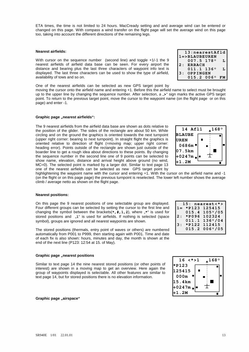
ETA times, the time is not limited to 24 hours. MacCready setting and and average wind can be entered or changed on this page. With compass a wind transfer on the flight page will set the average wind on this page too, taking into account the different directions of the remaining legs. Nearest airfields: With cursor on the sequence number (second line) and toggle +1/-1 the 9 nearest airfields of airfield data base can be seen. For every airport the distance and bearing plus the last three characters of waypoint info text is displayed. The last three characters can be used to show the type of airfield, availability of tows and so on. One of the nearest airfields can be selected as new GPS target point by moving the cursor onto the airfield name and entering +1. Before this the airfield name to select must be brought up to the upper line by changing the sequence number. After selection, a „>“ sign marks the active GPS target point. To return to the previous target point, move the cursor to the waypoint name (on the flight page or on this page) and enter -1. Graphic page „nearest airfields“: The 9 nearest airfields from the airfield data base are shown as dots relative to the position of the glider. The sides of the rectangle are about 50 km. While circling and on the ground the graphics is oriented towards the next turnpoint (upper right corner: bearing to next turnpoint). In straight flight the graphics is oriented relative to direction of flight (=moving map; upper right corner: heading error). Points outside of the rectangle are shown just outside of the boarder line to get a rough idea about directions to these points. By changing the sequence number in the second line one of 9 points can be selected to show name, elevation, distance and arrival height above ground (no wind, MC=0). The selected point is marked by a larger dot. Similar to text page 13 one of the nearest airfields can be selected as new GPS target point by highlightening the waypoint name with the cursor and entering +1. With the cursor on the airfield name and -1 (on the flight or on this page page) the previous turnpoint is reselected. The lower left number shows the average climb / average netto as shown on the flight page. Nearest positions: On this page the 9 nearest positions of one selectable group are displayed. Four different groups can be selected by setting the cursor to the first line and changing the symbol between the brackets(*,#,1,2), where „*“ is used for stored positions and „1“ is used for airfields. If nothing is selected (space symbol), groups are ignored and all nearest waypoints are shown. The stored positions (thermals, entry point of waves or others) are numbered automatically from P001 to P999, then starting again with P001. Time and date of each fix is also shown: hours, minutes and day, the month is shown at the end of the next line (P123: 12:54 at 15. of May). Graphic page „nearest positions Similar to text page 14 the nine nearest stored positions (or other points of interest) are shown in a moving map to get an overview. Here again the group of waypoints displayed is selectable. All other features are similar to text page 14, but for stored positions there is no elevation information. Graphic page „airspace“
13:nearestAfld 1=>BLAUBEUREN 007.5 178° L 2: ERBACH 011.1 136° L 3: OPPINGEN 015.2 006° FM
14 Afl1 168°BLAUBEUREN 0686m07.5km+0247m+1.2M
15: nearest<*> 1= *P123 125415 015.4 105°/05 2: *P096 102324 011.1 136°/04 3: *P122 112415 015.2 006°/05
16 <*>1 168°*P123125415 000m15.4km+0247m+1.2M

SR940E 1/01 22.01.01 14
On this page the information of the airspace data base within the SR940 is displayed. Up to 8 airspaces are shown. The orientation is always north up. The GPS position of the glider is always the dot in the center of the map. The heading of the glider is shown by two trailing dots. Each displayed airspace can be selected (AS#1...AS#8). A flashing sqare shows which airspace is selected and what is the nearest point of it. On the left side there is shown information concerning the selected airspace: the distance to it, the name and upper and lower levels. If the distance is negative, then the glider is inside the airspace. The levels are shown in multiples of 100 feet (like Flight Levels) or optionally as differences to the actual glider altitude in meters / feet with plus and minus. The number on the right border shows the maximum number of displayed airspaces. This number is determined by the zoom factor setting: low zoom factor shows up to eight airspaces, maximum zoom factor shows only one airspace border line. Sequence of cursor position and associated functions: „#“ airspace selection with +1/-1 „4“ change zoom factor with +1/-1 (sequence 8-4-2-1) „A“ jumps directly to altitude alarm page with +1 „-“ remove the selected airspace momentarily from airspace list with -1(the „-“ sign changes to „?+“); with +1 a deactivated airspace is made active again (same when turning on the SR940). Deactivation and activation takes about 15 seconds each before the display changes. cursor on upper limit: +1 switches to altitude difference mode for upper and lower levels, -1 returns to standard format. cursor on lower limit: +1 transfers lower limit to altitude alarm and jumps to altitude alarm page. In the upper right corner of the page the direction to the next turnpoint and in the lower left corner the average climb is shown like on the graphic pages 14 and 16. Due to rounding errors and uncertainties of airspace data there may be a difference of up to 100m between shown distance to an airspace and the logger evaluation later. So please note:
If a second backup logger is used with no airspace display, an additional 0.3km margin must be kept (0.6km in total) to be safe for the second logger. Battery voltage / temperature / airspeed: Indicated airspeed (IAS) can be used to check the internal airspeed sensor If IAS has a minus sign in flight, the ports „Pdyn+ = total“ and „Pdyn- = static“ are mixed up. IAS readings between -12km/h and +12km/h are o.k. on the ground. If there is a problem with the IAS shown: if the cursor is moved to the lower IAS line, an IAS zero adjust sequence can be initiated by using the +1/-1 toggle. Normally the zero adjust sequence is executed every ten minutes automatically. Statistics for the whole flight since departure: T stop watch D covered distance D/T average speed Atot gained altitude av.climb average climb circling circling percentage Statistics is cleared by pressing both -R- toggles and is counting only in flight. Covered distance is counted whenever the D calculator would count down (with compass in straight flight or without compass in speed command mode).
17 AS#1 168°04.5kmFRANKF #URT C 4FL 100 AMSL015 -+1.2M
When using the distance to airspace information keep a margin of 0.3km to an airspace border line!
18:Bat/Tmp/IAS battery voltage: 12.6 Volt outside airtemp: +024.9°C airspeed: (=IAS) +094kmh
19: Statistics T: 03:21 D: 0316km D/T: 094kmh Atot: 06200m av. climb: +1.25 circling: 041%
SR940E 1/01 22.01.01 15
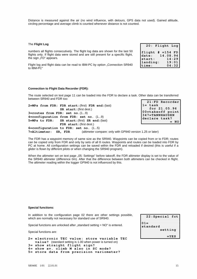
Distance is measured against the air (no wind influence, with detours, GPS data not used). Gained altitude, circling percentage and average climb is counted whenever distance is not counted. The Flight Log numbers all flights consecutively. The flight log data are shown for the last 50 flights only. If flight data were stored and are still present for a specific flight, the sign „FD“ appears. Flight log and flight data can be read to IBM-PC by option „Connection SR940 to IBM-PC“ Connection to Flight Data Recorder (FDR): The route selected on text page 11 can be loaded into the FDR to declare a task. Other data can be transferred between SR940 and FDR too: 2=WPs from FDR: FDR start:(first) FDR end:(last) SR start:(first dest.) 3=routes from FDR: set no.(1...9) 4=configuration from FDR: set no. (1...9) 5=WPs to FDR: SR start:(first) SR end:(last) FDR start:(first dest.) 6=configuration to FDR: set no. (1...5) 7=Altimeter: SR, FDR (altimeter compare: only with GP940 version 1.25 or later) The FDR has a waypoint memory of same size as the SR940. Waypoints can be copied from or to FDR; routes can be copied only from FDR and only by sets of all 8 routes. Waypoints and routes can be loaded into FDR by PC at home. All configuration settings can be saved within the FDR and reloaded if desired (this is useful if a glider is flown by different pilots or when changing the SR940 program). When the altimeter set on text page „05: Settings“ before takeoff, the FDR altimeter display is set to the value of the SR940 altimeter (difference 0m). After that the difference between both altimeters can be checked in flight. The altimeter reading within the logger GP940 is not influenced by this. Special functions: In addition to the configuration page 02 there are other settings possible, which are normally not necessary for standard use of SR940. Special functions are unlocked after „standard setting = NO“ is entered. Special functions are: 2= electronic TEC value: store variable TEC value? (standard setting is 1.00 when power is turned on) 3= show straight flight sign? 4= show av. climb M also in SC mode? 5= store data from precision variometer?
20: Flight Log flight # =154 FD date: 14.08.94 start: 14:29 landing: 19:01 time: 04:32
21:FD Recorder 1= task for 21.05.96 00=takeoff point 347=TANNHAUSEN declare task? = NO
22:Special fct 01= standard setting =YES
SR940E 1/01 22.01.01 16
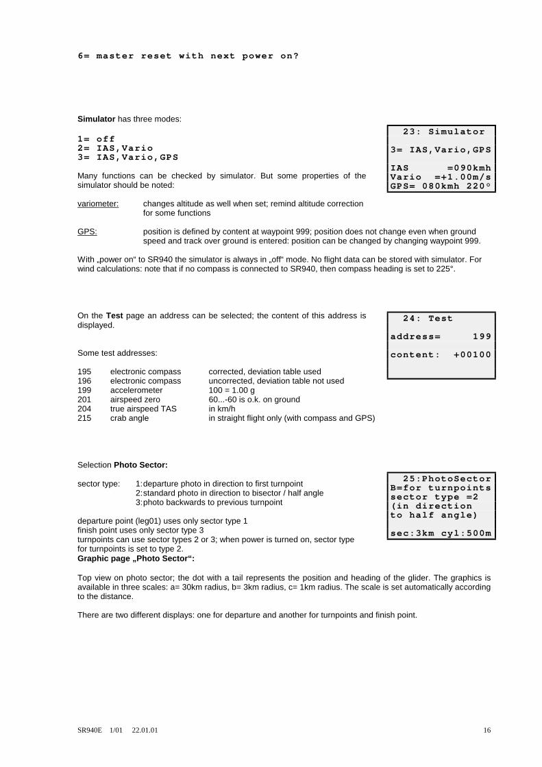
6= master reset with next power on? Simulator has three modes: 1= off 2= IAS,Vario 3= IAS,Vario,GPS Many functions can be checked by simulator. But some properties of the simulator should be noted: variometer: changes altitude as well when set; remind altitude correction for some functions GPS: position is defined by content at waypoint 999; position does not change even when ground speed and track over ground is entered: position can be changed by changing waypoint 999. With „power on“ to SR940 the simulator is always in „off“ mode. No flight data can be stored with simulator. For wind calculations: note that if no compass is connected to SR940, then compass heading is set to 225°. On the Test page an address can be selected; the content of this address is displayed. Some test addresses: 195 electronic compass corrected, deviation table used 196 electronic compass uncorrected, deviation table not used 199 accelerometer 100 = 1.00 g 201 airspeed zero 60...-60 is o.k. on ground 204 true airspeed TAS in km/h 215 crab angle in straight flight only (with compass and GPS) Selection Photo Sector: sector type: 1: departure photo in direction to first turnpoint 2: standard photo in direction to bisector / half angle 3: photo backwards to previous turnpoint departure point (leg01) uses only sector type 1 finish point uses only sector type 3 turnpoints can use sector types 2 or 3; when power is turned on, sector type for turnpoints is set to type 2. Graphic page „Photo Sector“: Top view on photo sector; the dot with a tail represents the position and heading of the glider. The graphics is available in three scales: a= 30km radius, b= 3km radius, c= 1km radius. The scale is set automatically according to the distance. There are two different displays: one for departure and another for turnpoints and finish point.
23: Simulator 3= IAS,Vario,GPS IAS =090kmh Vario =+1.00m/s GPS= 080kmh 220°
24: Test address= 199 content: +00100
25:PhotoSector B=for turnpoints sector type =2 (in direction to half angle) sec:3km cyl:500m

SR940E 1/01 22.01.01 17
Departure line: (visible if departure point is selected) The first three lines show sector type, photo angle, course deviation and distance to the startpoint. Photo angle is the angular difference between glider position and bisector line. Within photo sector the photo angle is 0°...45°, on the departure line the photo angle is exactly 90°. The arrow always shows in direction to the bisector line. The next line shows the perpendicular distance to the departure line or its extension, if outside of the departure gate. The next number shows the heading error to the departure line; if 000° is shown, the heading is perpendicular to the
departure line towards the first turnpoint. The next two lines show MSL altimeter and average climb / average netto (same as shown on flight page). With the 30km scale a 20km departure line is shown (2 x 10km), on other scales only a part of this line is visible; with scale 1km also a circle of 500m radius is shown.
Turnpoints / finish point: (visible if turnpoints or finish point is selected) The first three lines are the same as for departure line display. The next three lines are used to approach a turnpoint using an offset. The offset and side of offset must be set at first (example: „→300m“ means „300m to the right“). Then the next line shows a course deviation similar to line 2. But following the course deviation of line 5 will lead the glider to a point just 300m abeam the turnpoint to be able to round the turnpoint easily. The next two lines show MSL altitude and average climb / average netto as
shown on the departure line display. A black square close to the border line inside the top view picture shows the direction to the next turnpoint. With scale 1km also a circle of 500m radius is shown. If the finish point is selected, a 3km finish line is added to the photo sector display. 7. Configuration of SR940: Configuration settings are done on text page „02: Configure“. Before the SR940 is used first, all settings should be selected and checked. All settings are stored within the SR940 even if power is turned off. If power was not applied to SR940 for a longer time (3 month) or after a master reset, all settings should be checked again.
Selection of units for variometer, altitude, distance and wind. Depending on the units selected, units of other values like speed, temperature and wing loading will be selected accordingly. Function of main indicator unit in speed command mode: Option 2 (speed command / relative) function: normally speed error is shown until the netto relative variometer sees a climb rate larger than the MacCready setting; then the indicator switches to netto relative variometer. If MacCready setting is below 0.5m/s, then the limit value is kept at 0.5m/s.
26 Sek1:<065° <125°01.7km+0.8km <002° 1256m +0.5M
26 Sek2:<065° <021°01.7km>300m: =>002° 1256m +0.5M
01= Units: VA: A: D: W: 1= m/s m km kmh 2= m/s ft km kmh 3= kts ft mi kts 4= kts ft nm kts
02= Indicator #1 in SC mode: 1= speed command 2= SC / relative 3= relative 4= netto 5= variometer

SR940E 1/01 22.01.01 18
Option 2 should be used together with the option 2 of „05= audio signal in SC mode“ to use the same information for needle and audio.
Function of second indicator unit (optional) :
Option 1 shows at all times the speed error on second indicator (main indicator then may show variometer at all times). Option 2 and 3 are used for twin seater gliders; copy of #1 is also available at the speaker box, if average climb is needed for the second seat. Option 3 can be used for a range switch for the main instrument: 5m/s and 10m/s. Option 1 is of SR820 type: good differentiation between variometer and SC modes; excelent representation of increasing and decreasing climb rate; in quiet thermals even a step of 0.1m/s is noticable. Some training is necessary. Option 2 is of SR800 type Option 3 is similar to the commonly used audios; disadvantage: no differentiation between variometer and SC mode in sinking air. To make needle and audio similar, use the same mode for „02= indicator #1 in SC mode“ and „05=Audio signal in SC mode“ Option 2: see „02= indicator #1 in SC mode“ Option 3 and 4: note: the audio does not show which mode (variometer / SC) is selected.
If compass option is connected, select „with compass“ to get use of wind calculation with direction and speed (with GPS). The compass is also used for distincion of straight and circling flight (for statistics and distance counter, with or without GPS). If wind calculation does not work satisfactory, the compass function can be turned off with „no compass“. Compass deviation table: If the compass option is used, it is absolutely necessary to enter a deviation table into SR940. Otherwise the wind measurement with GPS is unusable. For wind calculation the deviation table must be accurate by 1°, as 1° produces a cross wind error of 2% of the true airspeed.
How to enter compass deviation table: Every 30° the glider is aligned by a reference compass or on a compass grid. The electronic compass heading information visible on the lower line is transferred by hand to the deviation table input. The „table entry“ function makes sequential inputs easier: after entering the first value, move the cursor further to the right; this increases automatically the table line number and brings the cursor directly to the correct position for entry of the next number. Compass deviation should not exceed 10°; otherwise the compass should be compensated first (see also 11. Compass and adjustment).
03= Indicator #2: 1= speed command 2= as #1 (2nd I) 3= average climb 4= twice of #1
04= audio typ in climb mode: 1= steps 2= continuous 3= intermittent
05= Audio signal in SC mode: 1= speed command 2= SC / relative 3= relative 4= variometer
06= Compass: 1= no compass 2= with compass
07= Compass Dev Tab: 01= at 000°=002° (Compass: 002°)
With GPS and compass: without deviation table no useful wind measurement! Compass deviation errors of 5 to 10°, which are quite common, will produce crosswind errors of 15 to 30 km/h at 150 km/h TAS; this leads to wind direction and speed informations which are absurd and useless!

SR940E 1/01 22.01.01 19
Total energy compensation can be done by TE probe or by computer. Each option requires different connections of pressure tubes. Type of compensation can be switched in flight if a pneumatic switch is installed. TE probe compensation is normally less complicated to achieve. The TE probe can be used together with another mechanical variometer. If a TE probe is used, the behavior of the variometer is only determined by the probe; static and total pressure ports are used for measurement of the airspeed only and do not
influence the variometer. Electronic TE compensation requires a very good static pressure port, which is not affected by rain drops or when dumping water ballast. Other problems are: nervous reactions of variometer in turbulent air, sensitivity to slide angle. Electronic compensation is used if no TE probe is installed or when the extractable engine of a motor glider is running.
TEC value determines how strong a change of airspeed will affect the variometer signal. TEC value for TE probe compensation is forced to 0.00 (not adjustable). TEC value for electronic compensation is normally set to 1.00, but can be adjusted in flight for test purposes. But experience shows that a static port which does not work properly with 1.00 is not usable for electronic compensation.
Option „electronic compensation“ can also be used to trim a TE probe: TEC values from -0.25 to +0.25 could be used (TEC value 0.00 means: compensation by probe only). TEC value for electronic compensation is always set to 1.00 when SR940 is turned on; this can be avoided by
„22: special functions“ setting. Time constants of variometer and speed command can be adjusted between 1.0 and 4.0 seconds. Recommended settings are: variometer 2.5s, speed command 3.5s. The time constant for average climb can be changed from 10 to 30 seconds. Recommended setting is 15s.
With accelerometer option only: An optimum speed is entered by hand (recalculated for wing loading 32 kp/m²). According to wing loading setting and g loads a speed limit is calculated. If airspeed is below this speed limit, the variometer audio sound changes. In SC mode this feature is turned off. A speed input of 000kmh turns of this function Without accelerometer option the g load is set to +1g; then this function is only of limited use. With accelerometer option only: Four typical speed limits are entered to define the borders between five flap positions ( +2 / +1 / 0 / -1 / -2 ); speeds are recalculated for wing loading of 32 kp/m². According to wing loading setting, g load and airspeed the optimum flap positition is shown on one of the info lines on the flight page („FP: -1“).
Automatic switching between variometer and speed command modes:
08= Total Energy: 1= with probe (Pstat=DUESE) 2= electronic (Pstat=STAT)
09= TEK value: = 0.00
10= Time Constants: variometer =2.5s speed comm.=3.5s averg.climb= 15s
11= with g meter: (kmh input for 32kpm²) ca-opt: =072kmh
12= Flap Computer: (kmh input for 32kpm²) 1=+2/+1:=076kmh

SR940E 1/01 22.01.01 20
Option 1: external switch (like flap switch) ON=variometer / OFF=SC Option 2: mode switching according to airspeed and wing loading setting (speed input is for 32kp/m² wing loading) Option 3: switches to variometer if climb rate is larger than MacCready setting (minimum 0.5m/s), switches to SC if climb rate is less and airspeed is larger than the speed input setting (speed input is for 32kp/m² wing loading). If non of both conditions apply, then the mode can changed by only a short, momentary action at the mode switch of SR940. Option 4: switches to variometer if vertical acceleration exceeds the g limit entered (only with accelerometer option). Returns to SC if vertical acceleration
is less. Recommended setting: 1.10g.
Aid for centering thermals: (see 4. Info Lines for more information) A beep, which will sound, when the glider is heading toward the better climb area while circling in a thermal, can be turned on and off or is on only, if the corresponding info line is selected on the flight page. An adjustable lead time of 0...9 seconds can compensate for delays. A gain limit can be set to avoid the beep if the expected improvement after recentering is too small.
Airspeed calibration: (to improve wind measurement) Airspeed correction table takes care of errors caused by pressure ports of the glider. For four measured (indicated) airspeeds (90/ 120 / 150 / 180 km/h) the adjusted (calibrated) airspeeds can be entered to improve wind measurement. Normally there is no adjustment necessary if the static ports are good enough for electronic compensation.
As the airspeed errors are related to the angle of attack, the corrections due to the calibration table are dependent on wing loading. So the correction for 90km/h is used for an IAS of 90km/h at 32kp/m2 and an IAS of 100km/h at 40kp/m2. So it is important to have the correct wing loading setting when doing the following tests. Evaluation of airspeed correction numbers is done in two steps: at first at low speed (at 90km/h for example), then at higher speeds. At low speed airspeed calibration can be done while circling. The circle must be less than one minute and flaps should be set according to the IAS in straight flight. After one or two circles on the lower line appeares the line with the „*“ sign. The airspeed used must be so that the IAS reading in the lower line shows the desired value (90km/h for example). The airspeed used is higher than this reading due to the wing loading set and due to the additional load factor while circling. Now the CAS reading shows, how much the CAS setting must be changed. If it shows zero, the calibration for that IAS is perfect. The same can be done for an IAS of 120km/h too, but not at higher IAS numbers, as the necessary flying speed gets too high. This way of calibration works only if there are no thermals, but any wind is eliminated. To calibrate at higher speeds, at first fly staight against or with the wind with IAS showing 120km/h. Wait until the wind component Wcp has stabilized. Now accelerate to 150km/h and wait again for about 20 seconds. If the wind component is different, adust the CAS setting accordingly and try again. Same can be done for IAS=180km/h, if it seems necessessary to have good wind information at that high speed. This way of measurement needs low wind and not too much wind shear with altitude.
Typical polar curves for three classes are available. These polar curves are described by quadratic equations. The polar curve used is modified in such way that the best L/D of the curve is equal to the „best L/D“ input on text page „05: settings“. With the same „best l/D“ input there are only small differences between the classes; the classes determine, how much sink rate increases at
13= Auto VA/SC: 1= ext. switch 2= at =100kmh (for 32kpm²) 3= =100kmh,cl<MC (for 32kpm²) 4= at =+1.10 g (with g meter)
14= Centering: 0= beep off 1= beep with info 2= beep on lead time =2s limit =0.2m/s
15= CAS calibr.: (for 32kpm2) 1= IAS: 090kmh CAS: =092kmh IAS=090: Wcp=-12 IAS=090:*CAS=+01
16= Polar type: 1= standard cl. 2= 15m FAI cl. 3= open class 4= special polar

SR940E 1/01 22.01.01 21
higher speeds. Users who are not satisfied with these simplifications may select their personal polar curve.
The personal polar curve must be recalculated for wing loading of 32 kp/m² (speeds and sink rates have to be multiplied by SQR(32/actual), best L/D is the same). The personal polar curve is a quadratic equation and is defined by three inputs: best L/D, speed at best L/D, speed at a sink rate of 2.0 m/s. However this polar curve will be modified too if the „best L/D“ input on text page „05: settings“ is not the same as on this page (the „best L/D“ input at „05: settings“ is used to cope with wet or bugged wings).
Number of free pages: 1...9 (see Organisation of pages). If two or more pages are selected, each page can be preprogrammed by a text page number. If only one free page is selected, this cannot be preprogrammed. Return to flight page with toggle page backwards can be step by step through all previous pages or directly by a jump to the flight page. All configuration settings of „02: Configure“ including page organisation and deviation table can be stored and later be reloaded with a special switch combination. To store all configuration data set PIN number to 4096 and enter YES (with +1 toggle). Then change the PIN number to avoid that uninformed persons can change the stored configuration data.
The stored configuration data will be reloaded if all three toggles of SR940 are moved upwards together.
Airspace alarm: When approaching an airspace border line from the outside, an audio alarm can be turned on. The alarm distance can be set between 1km and 9km. With the alarm tone the airspace page is selected to show the reason for the alarm.
Altitude alarm: Altitude alarm level is set as FL (flight level). The according MSL altitudes in feet and meter are shown. If a MSL altitude is to be set, the FL number must be changed until the desired MSL reading is shown. The QNH altimeter setting is shown for information only an cannot be changed on this page (can be changed on text page „05: Settings“). The alarm starts when approaching the altitude limit by about 50 meters during climb or sink. With the alarm tone
this text page is selected to show the reason for the alarm. To turn of the alarm function, select maximum FL number (= FL300).
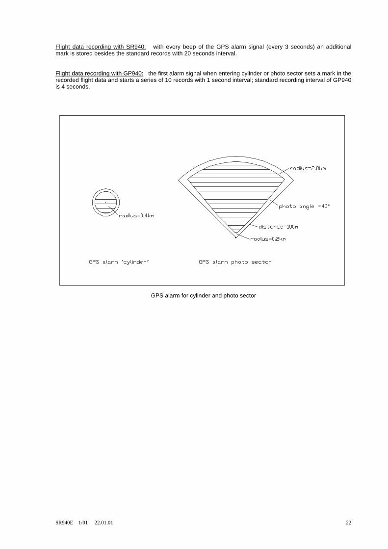
GPS alarm for cylinder or photo sector can be turned on and off on this submenue. The alarm borders are fixed to get a safety distance of about 100m compared to the standard dimensions for cylinder and photo sector (see drawing below). Safety distance is required, as glider computer and flight data recorder use different resolutions. If leg 00 (=takeoff point) is selected, there is no GPS alarm. So any unwanted GPS alarm signals on the ground before takeoff or in the air before
departure can be avoided by selecting leg 00 on the flight page.
17=Special Polar (for 32kgm²) best L/D ideal =40 at =101kmh -2.0m/s: =171kmh
18= free pages: number: =3 Page =1: Text=13 page backwards: 1= each page 2= jump back
19=store configuration: (PIN:=4096) store? = NO
20=Airspace Alarm: 0= no alarm 1= at distance 2.0km
21=Altitude Alarm: =FL075 1023hp = 07772ftMSL = 2370m MSL Alt.: 0634m MSL
22=GPS alarm 0= no alarm 1= cylinder R = 0.4km 2= photo sector R = 0.2 / 2.8km 3= cylinder and photosector
SR940E 1/01 22.01.01 22
Flight data recording with SR940: with every beep of the GPS alarm signal (every 3 seconds) an additional mark is stored besides the standard records with 20 seconds interval. Flight data recording with GP940: the first alarm signal when entering cylinder or photo sector sets a mark in the recorded flight data and starts a series of 10 records with 1 second interval; standard recording interval of GP940 is 4 seconds.
GPS alarm for cylinder and photo sector

SR940E 1/01 22.01.01 23
8. Version 01/99: changes compared to older versions Within the SR940 now are stored permanently : Airfield data base with up to 6000 entries Airspace data base The Waypoint list now shows on text page 10: 0001...0999 programmable user waypoints (unchanged to earlier versions) 1000...7000 airfield data base to read only, cannot be used for routes The list and graphic display of nearest airfields uses only the airfield data base; the GOTO function (route 0) can use the airfield data base too. Routes 1 to 8 can be programmed with user waypoints 0001...0999. The data base function of the GP940 is no longer used. Now a selection of nearest airfields can be copied from the airfield data base to the user waypoints 0001...0999. The list and graphic display of special positions uses the user waypoints 0001...0999 only. Four different groups of waypoints can be selected to be displayed. Text page 17 now shows airspace information. In the configuration menue airspace and altitude alarm can be set. A line showing airspace name, distance and direction is added to the info lines. On the flight page the information shown on the lower line can be changed like an info line between offset from course line / track over ground and wind force / direction. On text page 18 the zero adjustment of the airspeed sensor, which is done automatically every 10 minutes, can be activated by hand for test purposes. Airspeed calibration to improve wind measurement has been changed. Now calibration can be done while circling to eliminate the influence of wind during calibration. 9. Electrical connections: battery voltage 12 Volt (11 ... 15 Volt) current 110 mA red cable = „plus“ blue cable = „minus“ The SR 940 is safe against wrong polarity connectors at speaker box: ( red = + black = - ) 1 remote control open: speed command 2 remote control closed: variometer 3 indicator #1 (+) standard (main) indicator 4 indicator #1 (-) 5 temperature sensor 6 temperature sensor 7 indicator #2 (+) options: speed error, range switch, 2nd seat copy of #1,
2nd seat average climb 8 indicator #2, #3 (-) 9 indicator #3 (+) option: 2nd seat copy of #1 10 not used 11 not used 7 pin socket: used with compass option 2nd seat copy of #1: recommended connectors are pin 7, 8 and programming of SR940 for indicator #2; connectors 8, 9 can also be used but indicator may be influenced when pressing the radio button.
SR940E 1/01 22.01.01 24
Fuses: The SR940 should be connected with a fuse 2 ... 4 Amp (fast). A fuse of less than 1 Amp is not recommended as the larger voltage drop across such a fuse will stop operation of SR940 too early if the battery is weak. Automatic circuit breakers have large voltage drops too and are not recommended to be used with SR940. Temperature sensor: The temperature sensor measures the outside air temperature. A good place for this sensor is the fresh air hose. The sensor is put into it through a small hole. Important: the hole should be sealed after mounting, so no cold air will get to the pilot’s feet. The sensor should be mounted in a way that it stays removable (in case if it must be replaced). The SR940 will work without the temperaturesensor too; if the computer finds out, that the sensor is missing (temperature reading under -40°C), air density calculation uses temperature of standard atmosphere. External speaker: To connect an external speaker (for example at second seat of twin glider) disconnect the internal speaker within the speaker box, solder both wires to both free contacts 10 and 11. From here a cable may be connected to an external speaker ( 8 Ohm). GPS antenna: The GPS antenna is mounted horizontally (connector downwards). The antenna must have a good view of the sky, not obstructed by metall or carbon parts; glasfiber and plexiglas / acryl glas does not disturb GPS reception. A good place is on the cover of the instrument panel or just under it.
10. Pressure ports: The SR940 can be used with total energy compensation by probe or by computer as well. Normally the TE probe compensation works well at once. Electronic compensation requires a very good static pressure which is not disturbed by water drops in rain or when dumping water and is not sensitive to slide. The pressure tubes are connected differently at SR940 for both types of compensation. If a pressure switch is used, the type of compensation can be switched in flight. TE probe compensation: STAU = total pressure STAT = static pressure DÜSE = TE probe With TE probe compensation the static pressure is used only for airspeed measurement and does not influence the variometer. Only the TE probe influences the behavior of the variometer. Electronic compensation: + Pdyn = total pressure - Pdyn = good static pressure Pstat = good static pressure With electronic compensation the static pressure determines the quality of the variometer.
SR940E 1/01 22.01.01 25
Selectable compensation with pneumatic switch: To change type of compensation the pneumatic switch must be activated and SR940 must be reprogrammed to the type of compensation now used („02: Configure / 08= Total Energy“).
11. Compass and adjustment: Place to install: The compass should be mounted as far as possible away from magnetic and iron parts. Magnetic parts for example are indicator unit and to a lesser part speaker box of SR940. The distance between compass and indicator should be at minimum 15 to 20 cm; the compass should not be mounted above, under or besides the indicator but preferably at an angle of 45°. A good place for the compass is the cover of the instrument panel. Remove compensation unit: The compass has a compensation feature underneath the compass window behind a cover plate. The brass part with the two adjustment screws can be pulled out with a hook. Without this compensation unit the compass is more accurate as it is less affected by changes of nose up / nose down tilt angles. But if the deviation measurement shows errors of more than 10° then the compensation unit must be returned and compass compensation procedure must be done bevore deviation measurement.

SR940E 1/01 22.01.01 26
Compass compensation: Compass compensation is done only for mechanical indication of the compass. The glider is aligned to north and to south (in flying position - cannopy closed!). A same sign error for north and south readings can be reduced with the N/S adjustment screw until an opposite sign error remains only (opposite sign error is for example: north=+3°, south=-3°). Opposite sign errors cannot be removed. The same procedure is done for east / west headings with the E/W adjustment screw. When finnished both screws should be secured with removable glue. Deviation table: The glider must be aligned to a reference heading every 30°(all electronics turned on, in flying position, canopy closed!). Alignment can be done easily using the reference compass available from the SR940 manufacturer. This reference compass should be hanged on the TE probe at the tail to be far away from iron parts. For every 30° the electrical compass information is written down and after completion of full 360° is entered into the SR940 (see „02: Configure / 07= Compass Dev Tab“). It is recommended to write the numbers on the small template delivered with the compass to be able to check and restore the numbers (for example after Master Reset). Repeating deviation measurement: If a compass with compensation unit is used, deviation table measurement should be repeated from time to time (every year) or after a hard landings, as the compensating screws may loosen and may change the adjustment. Northern / southern hemisphere: Compasses without compensation unit can be used in both hemispheres as well; with compensation unit it may be better to measure a new deviation table at the other hemisphere. Wind measurement with compass and GPS: An accurate deviation table is very important for wind measurement with compass and GPS. Accuracy should be 1°. Without deviation table wind measurement is unusable, as common errors of 5 to 10° will deliver wrong crosswind components of 15 to 30 km/h at a true airspeed of 150 km/h (the wind component in direction of flight is not influenced by the compass). Such errors would lead to absurd wind speeds and directions. But with deviation table the fluid filled compass is well suited for this application, as wind measurement is only possible in quiet straigt flight condition with constant speed and no slide or slip angle (same effect as compass error). Checking wind measurement: Compass (straight flight) wind information can be compared with circling wind (outside thermals) as reference; circling wind does not use compass and is less sensitive to airspeed calibration errors. If straight flight wind information is unsatisfactory, some signals can be checked. First check if wind component is measured correctly. If yes, the problem is with the compass. The compass function can be checked with these test addresses: address 196 uncorrected compass signal (degrees, deviation table not used) 195 corrected compass signal (degrees, deviation table used) 215 crab angle (= difference between corrected compass signal and GPS track) Crab angle should be zero when flying against the wind, with the wind or when flying in no wind condition. If measurement of wind component is wrong, turn off compass function at „02: Configure / 06: Compass“ and try again. If wind component is better without compass, then the compass is not usable. If the indicated airspeed on page 18 differs by more than 3km/h, then the static port might not be good. The quality of the static port can be determined by using electronic TE compensation on this port. If electronic TE compensation is not usable, the selected static port is not very useful.

SR940E 1/01 22.01.01 27
12. Remote control: All toggle and switch functions of SR940 can be controllel in parallel by a connection at the rear of the computer housing. Please note that the front panel mode switch of SR940 must be in the center position to allow an external switch to control the mode variometer / automatic / speed command. Cables for remote control can be shielded or unshielded.
SR940E 1/01 22.01.01 28
13. Data link to PC: The SR940 can be linked to an IBM compatible PC by using the 15 pin connector on the rear side of SR940 (this connector is also used for remote control). A cable 15-9 (delivered with the glider computer) is used for this connection: 15 pin plug (to SR940): 9 pin socket (to PC): Pin 2 Pin 5 PC-GND Pin 3 Pin 3 PC-TX Pin 4 Pin 2 PC-RX To operate the SR940 outside of the glider, a cable 25-9-2 is used: 25 pin socket: to SR940 9 pin socket: to logger GP940 (optional) red +12 V / battery plus (use apropriate fuse!) blue 0 V / battery minus The 9 pin socket must not be connected to a PC !!! Sequence of operation to make a connection between SR940 and PC: Normally PC and SR940 are turned on and then the connecting cable is plugged in. If the desired program is started on the PC, it will show that connection has occured. If there is a problem to get connection, an alternative way should be tried: start PC program, turn off the SR940 and turn it on again while the PC program is still running and waiting for connection for about 30 seconds. On the diskette delivered with the SR940 you will find programs to change and load data: write, edit , load and read user waypoints edit and load airfield data bases load new programs into SR940 or change language of SR940 load new airspace data bases, attach or load own airspace information Information about using the programs you will find on the diskette in a file named „readme.txt“.

SR940E 1/01 22.01.01 29
15. Cable diagrams: (new version with flight data recorder)

SR940E 1/01 22.01.01 30
(upgraded versions with flight data recorder)