Embed Size (px)
Citation preview
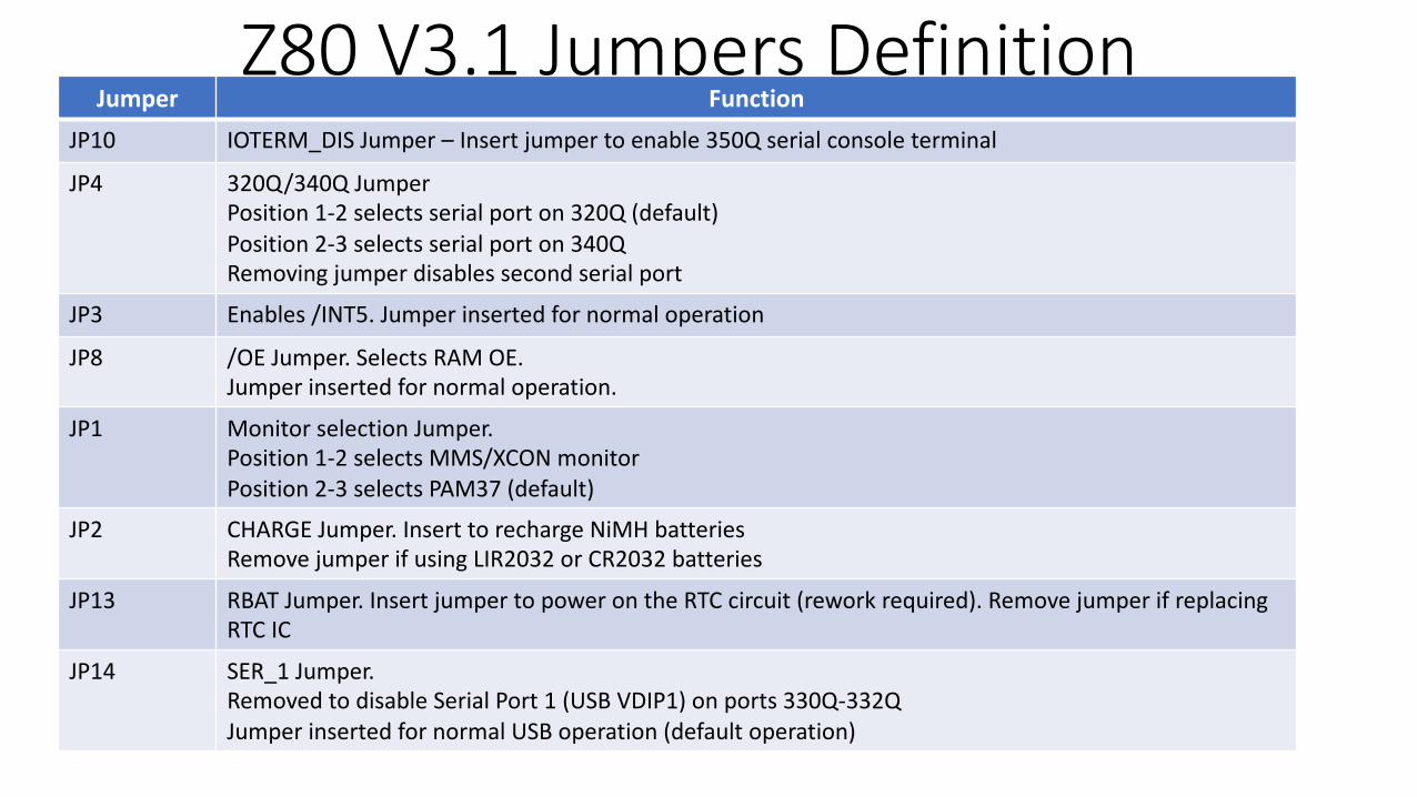
Z80 V3.1 Jumpers DefinitionJumper Function
JP10 IOTERM_DIS Jumper – Insert jumper to enable 350Q serial console terminal
JP4 320Q/340Q JumperPosition 1-2 selects serial port on 320Q (default)Position 2-3 selects serial port on 340QRemoving jumper disables second serial port
JP3 Enables /INT5. Jumper inserted for normal operation
JP8 /OE Jumper. Selects RAM OE. Jumper inserted for normal operation.
JP1 Monitor selection Jumper.Position 1-2 selects MMS/XCON monitorPosition 2-3 selects PAM37 (default)
JP2 CHARGE Jumper. Insert to recharge NiMH batteriesRemove jumper if using LIR2032 or CR2032 batteries
JP13 RBAT Jumper. Insert jumper to power on the RTC circuit (rework required). Remove jumper if replacing RTC IC
JP14 SER_1 Jumper. Removed to disable Serial Port 1 (USB VDIP1) on ports 330Q-332QJumper inserted for normal USB operation (default operation)
Z80 V3.1 Jumpers DefinitionJumper Function
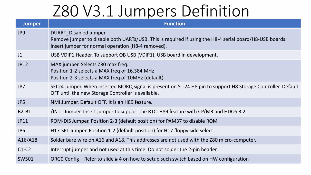
JP9 DUART_Disabled jumperRemove jumper to disable both UARTs/USB. This is required if using the H8-4 serial board/H8-USB boards.Insert jumper for normal operation (H8-4 removed).
J1 USB VDIP1 Header. To support OB USB (VDIP1). USB board in development.
JP12 MAX jumper. Selects Z80 max freq.Position 1-2 selects a MAX freq of 16.384 MHzPosition 2-3 selects a MAX freq of 10MHz (default)
JP7 SEL24 Jumper. When inserted BIORQ signal is present on SL-24 H8 pin to support H8 Storage Controller. Default OFF until the new Storage Controller is available.
JP5 NMI Jumper. Default OFF. It is an H89 feature.
B2-B1 /INT1 Jumper. Insert jumper to support the RTC. H89 feature with CP/M3 and HDOS 3.2.
JP11 ROM-DIS Jumper. Position 2-3 (default position) for PAM37 to disable ROM
JP6 H17-SEL Jumper. Position 1-2 (default position) for H17 floppy side select
A16/A18 Solder bare wire on A16 and A18. This addresses are not used with the Z80 micro-computer.
C1-C2 Interrupt jumper and not used at this time. Do not solder the 2-pin header.
SW501 ORG0 Config – Refer to slide # 4 on how to setup such switch based on HW configuration
Z80 V3.1 Jumpers DefinitionJumper Function
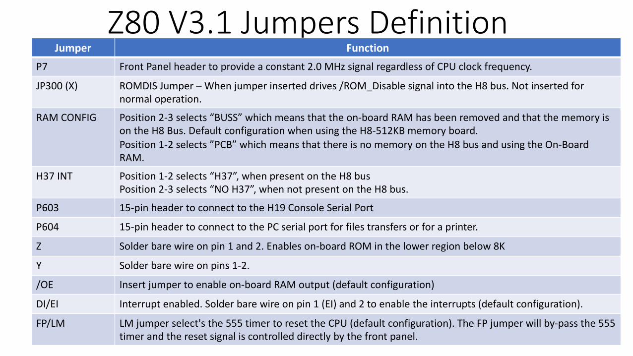
P7 Front Panel header to provide a constant 2.0 MHz signal regardless of CPU clock frequency.
JP300 (X) ROMDIS Jumper – When jumper inserted drives /ROM_Disable signal into the H8 bus. Not inserted for normal operation.
RAM CONFIG Position 2-3 selects “BUSS” which means that the on-board RAM has been removed and that the memory is on the H8 Bus. Default configuration when using the H8-512KB memory board.Position 1-2 selects ”PCB” which means that there is no memory on the H8 bus and using the On-Board RAM.
H37 INT Position 1-2 selects “H37”, when present on the H8 busPosition 2-3 selects “NO H37”, when not present on the H8 bus.
P603 15-pin header to connect to the H19 Console Serial Port
P604 15-pin header to connect to the PC serial port for files transfers or for a printer.
Z Solder bare wire on pin 1 and 2. Enables on-board ROM in the lower region below 8K
Y Solder bare wire on pins 1-2.
/OE Insert jumper to enable on-board RAM output (default configuration)
DI/EI Interrupt enabled. Solder bare wire on pin 1 (EI) and 2 to enable the interrupts (default configuration).
FP/LM LM jumper select's the 555 timer to reset the CPU (default configuration). The FP jumper will by-pass the 555 timer and the reset signal is controlled directly by the front panel.
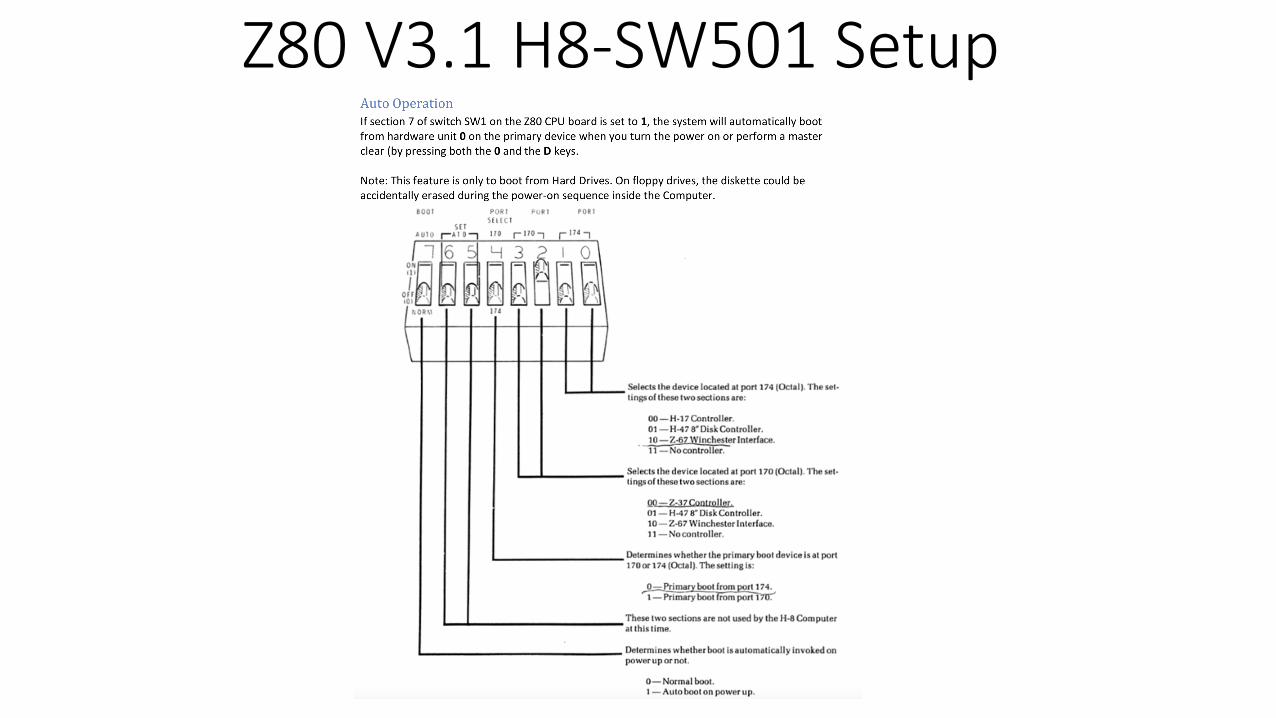
Z80 V3.1 H8-SW501 Setup
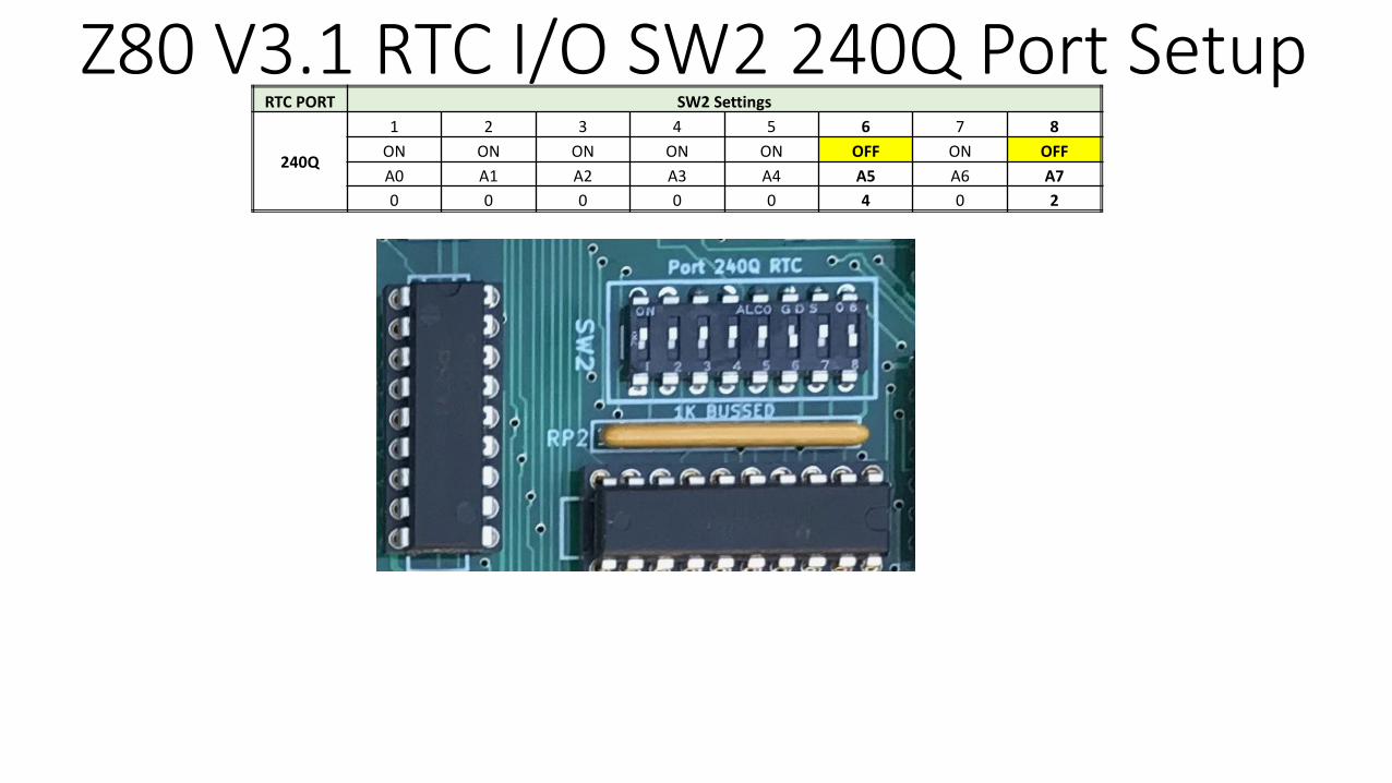
Z80 V3.1 RTC I/O SW2 240Q Port SetupRTC PORT SW2 Settings
240Q
1 2 3 4 5 6 7 8ON ON ON ON ON OFF ON OFFA0 A1 A2 A3 A4 A5 A6 A70 0 0 0 0 4 0 2
![The Z80 Family Program Interrupt Structure [****]z80.info/zip/z80-interrupts_rewritten.pdf · THE Z80 FAMILY PROGRAM INTERRUPT STRUCTURE Visit Zilog at ! 20101110 / document version](https://img.dokumen.tips/doc/110x75/5b1542b67f8b9af15d8e48e6/the-z80-family-program-interrupt-structure-z80infozipz80-interrupts-.jpg)