Embed Size (px)
Citation preview

YSI 556 MPSSet-up, Operation & Calibration

YSI 556 MPS
The YSI 556 is just one of the instruments included in the
Environment Agency UK Framework agreement.
The YSI 556 is a field rugged and reliable Multi-Probe System that
combines the versatility of an easy-to-use, easy-to-read handheld
unit with all the functionality of a multi-parameter system.
Featuring a waterproof (IP67), impact resistant case, the YSI 556
simultaneously measures dissolved oxygen, conductivity,
temperature, pH and ORP (Redox).
Conforms to GLP standards to help ensure quality control.
Standard RS232 interface to Ecowatch for Windows. Capable of
storing 49,000 data sets.

Rugged Probe Guard
Field rugged case,
waterproof to IP67
Field replaceable
electrodes
Standard RS232,
compatible with Ecowatch
for Windows™
DO cap
membranes
Three-year meter warranty
Stores 49,000 data sets,
time and date stamped
Simultaneous display
of all data
YSI 556 Key Features

Optional Features
Optional internal barometer (user calibrated and displayed
along with other data, used in dissolved oxygen calibrations,
and logged to memory for tracking changes in barometric
pressure.
5083 Optional flow cell
6094 Rechargeable battery back kit
5085 Hand-free harness
616 Cigarette lighter charger kit
6081 Large carrying case, hard-sided
5065 Form fitted carrying case

YSI 556 MPS
SET-UP
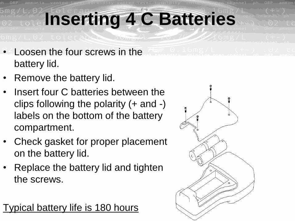
Inserting 4 C Batteries
• Loosen the four screws in the
battery lid.
• Remove the battery lid.
• Insert four C batteries between the
clips following the polarity (+ and -)
labels on the bottom of the battery
compartment.
• Check gasket for proper placement
on the battery lid.
• Replace the battery lid and tighten
the screws.
Typical battery life is 180 hours

Inserting Rechargeable Battery
Pack• Loosen the four screws in the
battery lid on the back of the
instrument using any screwdriver.
• Remove the C battery lid and store
for future use. Remove C batteries,
if installed.
• Check for proper placement of
gasket on the rechargeable battery
pack and lid.
• Install the rechargeable battery
pack and lid and tighten the 4
screws securely and evenly
Typical battery life is 50 hours
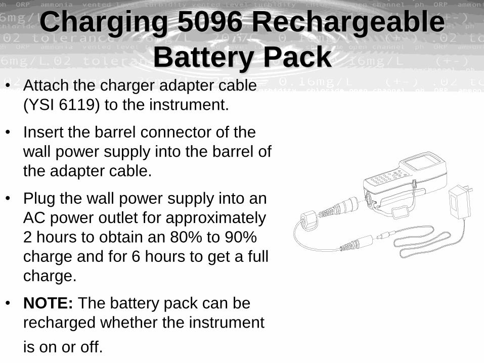
Charging 5096 Rechargeable
Battery Pack• Attach the charger adapter cable
(YSI 6119) to the instrument.
• Insert the barrel connector of the
wall power supply into the barrel of
the adapter cable.
• Plug the wall power supply into an
AC power outlet for approximately
2 hours to obtain an 80% to 90%
charge and for 6 hours to get a full
charge.
• NOTE: The battery pack can be
recharged whether the instrument
is on or off.

Setting Display Contrast
• Press and hold down the backlight
key in the upper right corner of the
keypad and press the “up” arrow to
increase (darken) the contrast.
• Press and hold down the backlight
key in the upper right corner of the
keypad and press the “down” arrow
to decrease (lighten) the contrast. Backlight
key

Screen Features
Main display
Status bar
Barometer reading
(optional). Updated in real
time, not corrected to sea
level.
Battery charge, pulsing
indicates that battery is
charging, flashing indicates
that batteries almost
exhausted.
Current time
Current date

Keypad Features
Backlight / Contrast
Arrows Keys
Enter Key
Period/Decimal Point Key
On/Off Key
Escape Key - Use to return
to previous position in menu
Alpha/Numeric Keys - Used
to enter letters and numbers
Minus/Hyphen (-) Key

R u n
R e p o r t
C a l i b r a t e
S e n s o r
F i l e
L o g g i n g S e t u p
S y s t e m S e t u p
S p e c i f i c C o n d u c t a n c e
S a l i n i t y p p t
T e m p e r a t u r e
C o n d u c t i v i t y
R e s i s t i v i t y
T D S
D O % s a t u r a t i o n
D O m g / L
p H
p H m v
O R P m v
C o n d u c t i v i t y
T e m p e r a t u r e
D i s s o l v e d O x y g e n
p H
O R P
S t a r t L o g g i n g
L o g O n e S a m p l e
D O
C o n d u c t i v i t y
p H
O R P
U p l o a d t o P C
D I r e c t o r y
V i e w F i l e
F i l e M e m o r y
D e l e t e A l l F i l e s
U s e S i t e L i s t
I n t e r v a l
S t o r e B a r o m e t e r
S t o r e S i t e N u m b e r
E d i t S i t e L i s t
D a t e & T i m e
I D
V e r s i o n
D a t a F i l t e r
S h u t O f f T i m e
C o m m a R a d i x
G L P F i l e n a m e
T D S C o n s t a n t
B a r o m e t e r U n i t s
C a l i b r a t e B a r o m e t e r
YSI 556 MPS
SENSORS

YSI 5563 Probe Module
Cable
Dissolved
Oxygen (DO)
Probe
Transport /
Calibration
Cup
Strain Relief
Metal Probe
Connector Nut
pH/ORP
Probe
Conductivity /
Temperature
Probe
Probe Sensor
Guard

Installing the Sensors• Unscrew and remove probe guard
• Unscrew and remove sensor port plugs
• Locate the port with the connector that
corresponds to the sensor that is to be
installed.
• Apply a thin coat of o-ring lubricant to
the o-rings on the connector side of the
sensor.
• Be sure that the probe module sensor is
free of moisture and the insert the
sensor.
• Screw down the sensor nut using the
YSI tool. Do not overtighten.
O-Rings Sensor nut

Install DO MembraneA new membrane cap must be installed before the first
use.
• Unscrew and remove the probe sensor guard.
• Unscrew, remove, and discard the old membrane cap.
• Thoroughly rinse the sensor tip with distilled water.
• Prepare the electrolyte according to the directions on the
electrolyte solution bottle.
• Hold the new membrane cap and fill it at least 1/2 full with the
electrolyte solution.
• Screw the membrane cap onto the sensor moderately tight. A
small amount of electrolyte should overflow.

Enable Sensors
• Press the On/Off key to
display the Run screen.
• Press the Escape key to
display the main menu
screen
• Use the arrow keys to
highlight the Sensor
selection.
• Press the Enter key to
display the sensors enabled
screen

Change Report
• Press the On/off key to
display the run screen.
• Press the Escape key to
display the main menu
screen.
• Use the arrow keys to
highlight the Report
selection.
• Press the Enter key to
display the report setup
screen.

View all Parameters

YSI 556 MPS
CALIBRATION

Calibration Tips• Ensure Transport/Calibration Cup is loose to allow pressure equilibration before
calibration.
• The key to successful calibration is to ensure that the sensors are completely
submersed.
• For maximum accuracy, use a small amount of previously used calibration solution
to pre-rinse the probe module.
• Fill a bucket with ambient temperature water to rinse the probe module between
calibration solutions.
• Have several clean, absorbent paper towels or cotton cloths available to dry the
probe module between rinses and calibration solutions.
• If you are using laboratory glassware, remove the stainless steel weight from the
bottom of the probe sensor guard by turning the weight counterclockwise. When
the weight is removed, the calibration solutions have access to the sensors without
displacing a lot of fluid.
• Make certain that port plugs are installed in all ports where sensors are not
installed. It is extremely important to keep these electrical connectors dry.

Accessing the Calibration Mode
• Press the On/off key to
display the run screen.
• Press the Escape key to
display the main menu
screen.
• Use the arrow keys to
highlight the Calibration
selection.
• Press the Enter key to
display the Calibration
screen.

Conductivity• Use the arrow keys to highlight the
Conductivity selection.
• Press Enter. The Conductivity Calibration
Selection Screen is displayed.
• Use the arrow keys to highlight the Specific
Conductance selection.
• Press Enter. The Conductivity Calibration
Entry Screen is displayed.
• Place the correct amount of conductivity
standard into a clean, dry or pre-rinsed
transport /calibration cup.
• Carefully immerse the sensor end of the probe
module into the solution.
• Gently rotate and/or move the probe module up
and down to remove any bubbles from the
conductivity cell.
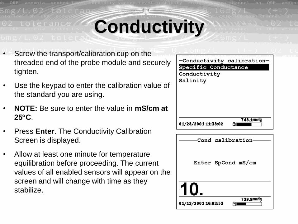
Conductivity
• Screw the transport/calibration cup on the
threaded end of the probe module and securely
tighten.
• Use the keypad to enter the calibration value of
the standard you are using.
• NOTE: Be sure to enter the value in mS/cm at
25C.
• Press Enter. The Conductivity Calibration
Screen is displayed.
• Allow at least one minute for temperature
equilibration before proceeding. The current
values of all enabled sensors will appear on the
screen and will change with time as they
stabilize.

Conductivity• Observe the reading under Specific
Conductance. When the reading shows no
significant change for approximately 30
seconds, press Enter. The screen will
indicate that the calibration has been
accepted and prompt you to press Enter
again to Continue.
• Press Enter. This returns you to the
Conductivity Calibrate Selection Screen.
• Press Escape to return to the calibrate
menu.
• Rinse the probe module and sensors in tap
or purified water and dry.

Dissolved Oxygen• NOTE: The instrument must be on for at least
20 minutes to polarize the DO sensor before
calibrating.
• Use the arrow keys to highlight the Dissolved
Oxygen selection.
• Press Enter. The dissolved oxygen calibration
screen is displayed.
• Use the arrow keys to highlight the DO%
selection.
• Press Enter. The DO Barometric Pressure
Entry Screen is displayed.
• Place approximately 3 mm (1/8 inch) of water in
the bottom of the transport/calibration cup.
• Place the probe module into the
transport/calibration cup.

Dissolved Oxygen• NOTE: Make sure that the DO and
temperature sensors are not immersed in the
water.
• Engage only 1 or 2 threads of the
transport/calibration cup to ensure the DO
sensor is vented to the atmosphere.
• Use the keypad to enter the current local
barometric pressure.
• NOTE: If the unit has the optional barometer,
no entry is required.
• NOTE: Barometer readings that appear in
meteorological reports are generally corrected
to sea level and must be uncorrected before
use.
• Press Enter. The DO% saturation calibration
screen is displayed.

Dissolved Oxygen• Allow approximately ten minutes for the air in
the transport/calibration cup to become water
saturated and for the temperature to equilibrate
before proceeding. The current values of all
enabled sensors will appear on the screen and
will change with time as they stabilize.
• Observe the reading under DO %. When the
reading shows no significant change for
approximately 30 seconds, press Enter. The
screen will indicate that the calibration has
been accepted and prompt you to press Enter
again to Continue.
• Press Enter. This returns you to the DO
calibration screen.
• Press Escape to return to the calibrate menu.
• Rinse the probe module and sensors in tap or
purified water and dry.

pH• Use the arrow keys to highlight the pH selection.
• Press Enter. The pH calibration screen is
displayed.
– Select the 1-point option only if you are
adjusting a previous calibration.
– Select the 2-point option to calibrate the pH
sensor using only two calibration standards.
Use this option if the media being monitored
is known to be either basic or acidic.
– Select the 3-point option to calibrate the pH
sensor using three calibration solutions. In
this procedure, the pH sensor is calibrated
with a pH 7 buffer and two additional buffers.
The 3-point calibration method assures
maximum accuracy when the pH of the
media to be monitored cannot be
anticipated.

pH• Use the arrow keys to highlight the 2-point
selection.
• Press Enter. The pH Entry Screen is displayed.
• Place the correct amount of pH buffer into a
clean, dry or pre-rinsed transport/calibration cup.
• Carefully immerse the sensor end of the probe
module into the solution.
• Gently rotate and/or move the probe module up
and down to remove any bubbles from the pH
sensor.
• Use the keypad to enter the calibration value of
the buffer you are using at the current
temperature. (check YSI bottles)
• Press Enter. The pH calibration screen is
displayed.

pH• Allow at least one minute for temperature
equilibration before proceeding.
• When the reading shows no significant change
for approximately 30 seconds, press Enter. The
screen will indicate that the calibration has been
accepted and prompt you to press Enter again
to Continue.
• Press Enter. This returns you to the Specified
pH Calibration Screen.
• Rinse the probe module, transport/calibration
cup and sensors in tap or purified water and dry.
• Repeat steps 6 through 13 above using a
second pH buffer.
• Press Enter. This returns you to the pH
Calibration Screen, See .
• Press Escape to return to the calibrate menu.

• Use the arrow keys to highlight the ORP
selection. Press Enter. The ORP calibration
screen is displayed.
• Place the correct amount of a known ORP
solution (we recommend Zobell solution) into a
clean, dry or pre-rinsed transport/calibration cup.
• Carefully immerse the sensor end of the probe
module into the solution.
• Gently rotate and/or move the probe module up
and down to remove any bubbles from the ORP
sensor.
• Allow at least one minute for temperature
equilibration before proceeding. The current
values of all enabled sensors will appear on the
screen and will change with time as they
stabilize.
ORP
Temperature °C Zobell Solution Value, mV
-5 270.0
0 263.5
5 257.0
10 250.5
15 244.0
20 237.5
25 231.0
30 224.5
35 218.0
40 211.5
45 205.0
50 198.5

ORP
• NOTE: Verify that the temperature reading
matches the value you used in .
• Observe the reading under ORP, when the
reading shows no significant change for
approximately 30 seconds, press Enter. The
screen will indicate that the calibration has been
accepted and prompt you to press Enter again
to Continue.
• Press Enter. This returns you to the Calibrate
Screen. See .
• Rinse the probe module and sensors in tap or
purified water and dry.

Return to Factory Settings• NOTE: We will use the Conductivity sensor as
an example; however, this process will work for
any sensor.
• Press Enter. The Conductivity Calibration
Selection Screen is displayed.
• Use the arrow keys to highlight the Specific
Conductance selection.
• Press Enter. The Conductivity Calibration Entry
Screen is displayed. See .
• Press and hold the Enter key down and press
the Escape key.
• Use the arrow keys to highlight the YES
selection.
• Press Enter. This returns you to the Conductivity
Calibrate Selection Screen.
YSI 556 MPS
RUN

Real-Time Data• Press the On/off key or select Run from the
main menu to display the run screen.
• Make sure the probe sensor guard is installed.
• Place the probe module in the sample. Be sure
to completely immerse all the sensors.
• Rapidly move the probe module through the
sample to provide fresh sample to the DO
sensor. (Note the DO sensor requires a flow rate
of 1ft per seconds. Use a motion similar to
dipping a tea bag)
• Watch the readings on the display until they are
stable.
• For logging see later section.

YSI 556 MPS
FILE

File
• Press the On/off key to display the run screen.
• Press the Escape key to display the main menu
screen.
• Use the arrow keys to highlight the File
selection.
• Press the Enter key. The file screen is
displayed.

Directory
• Use the arrow keys to highlight the Directory
selection.
• Press the Enter key. The file list screen is
displayed.
• NOTE: Files are listed in the order in which they
are logged to memory. Sample Data files have
the file extension .dat, while Calibration Record
files have the file extension .glp.
• Use the arrow keys to highlight a file.
• Press the Enter key. The file details screen is
displayed.
• Press the Enter key to view the file data. Refer
to Section for details.
• Press the Escape key repeatedly to return to the
main menu screen.

View File• Use the arrow keys to highlight the View file
selection.
• Press the Enter key. A list of files is displayed.
• Use the arrow keys to highlight an individual file.
• NOTE: You may have to scroll down to see all
the files.
• Press the Enter key. The file data is displayed
with the file name at the top of the display.
• NOTE: If no file name was specified, the data is
stored under the default name NONAME1.dat.
• Use the arrow keys to scroll horizontally and/or
vertically to view all the data.
• Press the Escape key repeatedly to return to the
main menu screen.
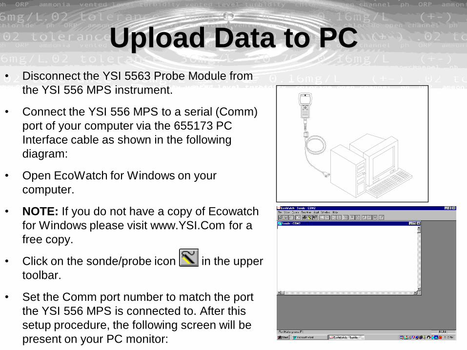
Upload Data to PC• Disconnect the YSI 5563 Probe Module from
the YSI 556 MPS instrument.
• Connect the YSI 556 MPS to a serial (Comm)
port of your computer via the 655173 PC
Interface cable as shown in the following
diagram:
• Open EcoWatch for Windows on your
computer.
• NOTE: If you do not have a copy of Ecowatch
for Windows please visit www.YSI.Com for a
free copy.
• Click on the sonde/probe icon in the upper
toolbar.
• Set the Comm port number to match the port
the YSI 556 MPS is connected to. After this
setup procedure, the following screen will be
present on your PC monitor:

Upload a .DAT File• Use the arrow keys to highlight the Upload to
PC selection.
• Press the Enter key. The file list screen is
displayed.
• Use the arrow keys to highlight the DAT file
that you wish to transfer and press Enter, both
the YSI 556 MPS and PC displays show the
progress of the file transfer.
• After transfer, the file will be located in the
C:\ECOWWIN\DATA folder of your PC,
designated with a .DAT extension.
• After the file transfer is complete, close the
terminal window (small window on the PC) by
clicking on the “X” at its upper right corner.
• Press the Escape key on the YSI 556 MPS
repeatedly to return to the main menu screen.
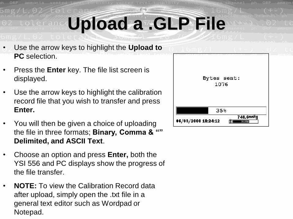
Upload a .GLP File• Use the arrow keys to highlight the Upload to
PC selection.
• Press the Enter key. The file list screen is
displayed.
• Use the arrow keys to highlight the calibration
record file that you wish to transfer and press
Enter.
• You will then be given a choice of uploading
the file in three formats; Binary, Comma & “”
Delimited, and ASCII Text.
• Choose an option and press Enter, both the
YSI 556 and PC displays show the progress of
the file transfer.
• NOTE: To view the Calibration Record data
after upload, simply open the .txt file in a
general text editor such as Wordpad or
Notepad.

Exporting .DAT File in ExcelEcowatch for Windows
• Open .dat file by pressing File..Open..(desired
file name).
• After file has opened click File..Export..DBF
MS Excel
• Open .dbf file by pressing File..Open..(desired
file name.dbf)
• ENSURE TO SELECT ALL FILES OPTION
• File should automatically open as a .xls file.

YSI 556 MPS
LOGGING
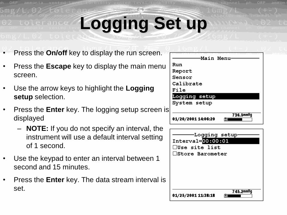
Logging Set up
• Press the On/off key to display the run screen.
• Press the Escape key to display the main menu
screen.
• Use the arrow keys to highlight the Logging
setup selection.
• Press the Enter key. The logging setup screen is
displayed
– NOTE: If you do not specify an interval, the
instrument will use a default interval setting
of 1 second.
• Use the keypad to enter an interval between 1
second and 15 minutes.
• Press the Enter key. The data stream interval is
set.

Site List• Use the arrow keys to highlight the Use site list
selection.
• Press the Enter key. A check mark is entered in
the box next to the use site list selection and two
new entries appear on the logging setup screen.
• Use the arrow keys to highlight the Store site
number selection.
• If you are creating Multi-Site Descriptions (which
require that the site number be stored in your
data files), press the Enter key until a check
mark appears in the box next to the store site
number selection.
• OR Press the Enter key until the box next to the
store site number selection is empty, to create
Single-Site Descriptions. The site name will be
stored in the header of your data files.
• Use the arrow keys to highlight the Edit site list
selection.

Site List
• Press the Enter key. The edit site list screen is
displayed. See . The Filename field is ready for
input.
• Use the keypad to enter a filename up to 8
characters in length.
• Press the Enter key. The cursor moves to the
right for the entry of a Site name.
• Use the keypad to enter a site name up to 11
characters in length.
• Press the Enter key. The cursor moves to the
site number entry position.
• Use the keypad to enter a site number up to 7
characters in length.
• Press Enter. The cursor moves to the next
filename entry position.

Logging Data Without a Site List• Use the arrow keys to highlight the Log one
sample selection on the run screen if only a
single sample is being logged.
• OR Use the arrow keys to highlight the Start
logging selection on the run screen if a data
stream is being logged.
• Press the Enter key. The Enter information
screen is displayed.
• NOTE: The last filename used will be displayed.
• Use the keypad to enter a file name.
• NOTE: The instrument will assign a default file
name of NONAME if no file name is specified.
• Press the Enter key to input the file name.
• Use the arrow keys to highlight the Site
description field in the enter information screen.

Logging Data Without a Site List• Use the keypad to enter a site description name.
• Press the Enter key to input the site description.
• NOTE: If you want to change the logging setup,
such as sampling interval or storing the
barometer reading, use the arrow keys to
highlight the Configure field, press the Enter
key.
• Use the arrow keys to highlight the OK field in
the center of the information screen.
• Press the Enter key to start logging.
• If a single point is being logged, the header on
the run screen changes momentarily from Menu
to Sample logged to confirm that the point was
successfully logged.
• If a continuous stream of points is being logged,
the start logging entry in the run screen changes
from Start logging to Stop logging.

Logging Data With a Site List• Use the arrow keys to highlight the Log one
sample selection on the run screen if only a
single sample is being logged.
• OR Use the arrow keys to highlight the Start
logging selection on the run screen if a data
stream is being logged.
• Press the Enter key. The Pick a site screen is
displayed. Use the arrow keys to highlight the
site of your choice.
• Press the Enter key to start logging.
• If a single point is being logged, the header on
the run screen changes momentarily from Menu
to Sample logged to confirm that the point was
successfully logged. See . Skip to Step 9.
• If a continuous stream of points is being logged,
the start logging entry in the run screen changes
from Start logging to Stop logging.

YSI 556 MPS
SYSTEM SET-UP

System Set-Up
• Time / date
• Data filters
• Shut off time
• Comma radix
• ID
• GLP filename
• Barometer units
• Calibrate Barometer

Calibrate Barometer
• Determine your local barometric pressure from
an independent laboratory barometer or from
your local weather service.
• If the barometric pressure (BP) reading is from
your local weather station, reverse the equation
that corrects it to sea level.
• NOTE: For this equation to be accurate, the
barometric pressure units must be in mm Hg.
• True BP = (Corrected BP) – [2.5 * (Local
Altitude/100)]
• Use the arrow keys to highlight the Calibrate
barometer selection on the system setup
screen. See .
• Press the Enter key. The Calibrate Barometer
screen is displayed.
YSI 556 MPS
MAINTENANCE

Dissolved OxygenFor best results, we recommend that the KCl solution and the membrane cap be
changed at least once every 30 days.
• The rate of stirring should be at least 1 foot per second.
• Membrane life depends on usage. Erratic readings are a result of loose, wrinkled,
damaged, or fouled membranes, or from large (more than 1/8" diameter) bubbles in
the electrolyte reservoir. The average replacement interval is two to four weeks.
• If the membrane is coated with oxygen consuming (e.g. bacteria) or oxygen
producing organisms (e.g. algae), erroneous readings may occur.
• Chlorine, sulfur dioxide, nitric oxide, and nitrous oxide can affect readings by
behaving like oxygen at the sensor. If you suspect erroneous readings, it may be
necessary to determine if these gases are the cause.
• Avoid any environment that contains substances that may attack the probe module
and sensor materials. Some of these substances are concentrated acids, caustics,
and strong solvents. The sensor materials that come in contact with the sample
include FEP Teflon, acrylic plastic, EPR rubber, stainless steel, epoxy,
polyetherimide and the PVC cable covering.

Dissolved Oxygen
• It is possible for the silver anode, which is the entire silver body of the sensor, to
become contaminated. This will prevent successful calibration.
• For correct sensor operation, the gold cathode must always be bright. If it is
tarnished (which can result from contact with certain gases), or plated with silver
(which can result from extended use with a loose or wrinkled membrane), the gold
surface must be restored.
• To keep the electrolyte from drying out, store the sensor in the transport/calibration
cup with at least 1/8 of water.
Silver Anode Cleaning
– After extended use, a thick layer of AgCl builds up on the silver anode reducing
the sensitivity of the sensor. The anode must be cleaned to remove this layer and
restore proper performance. The cleaning can be chemical or mechanical:
– Chemical Cleaning: Remove the membrane cap and soak the entire anode
section in a 14% ammonium hydroxide solution for 2 to 3 minutes, followed by a
thorough rinsing with distilled or deionized water. The anode should then be
thoroughly wiped with a wet paper towel to remove the residual layer from the
anode.
– Mechanical Cleaning: Sand off the dark layer from the silver anode with 400 grit
wet/dry sandpaper. Wrap the sandpaper around the anode and twist the sensor.
Rinse the anode with clean water after sanding, followed by wiping thoroughly
with a wet paper towel.
– NOTE: After cleaning, a new membrane cap must be installed.
– Turn the instrument on and allow the system to stabilize for at least 30 minutes.
If, after several hours, you are still unable to calibrate, contact Hydrodata
Services UK Limited

Gold Cathode Cleaning
– For correct sensor operation, the gold cathode must be textured properly. It can
become tarnished or plated with silver after extended use. The gold cathode can
be cleaned by using the adhesive backed sanding disc and tool provided in the
YSI 5238 Probe Reconditioning Kit.
– Using the sanding paper provided in the YSI 5238 Probe Reconditioning Kit, wet
sand the gold with a twisting motion about 3 times or until all silver deposits are
removed and the gold appears to have a matte finish. Rinse the cathode with
clean water after sanding, followed by wiping thoroughly with a wet paper towel.
If the cathode remains tarnished, contact Hydrodata Services UK Limited.
– NOTE: After cleaning, a new membrane cap must be installed.
pH / ORP (Stage 1)
• Cleaning is required whenever deposits or contaminants appear on the glass and/or
platinum surfaces of these sensors or when the response of the sensor becomes
slow.
• Remove the sensor from the probe module.
• Initially, simply use clean water and a soft clean cloth, lens cleaning tissue, or cotton
swab to remove all foreign material from the glass bulb (YSI 5564 and YSI 5565) and
platinum button (YSI 5565). Then use a moistened cotton swab to carefully remove
any material that may be blocking the reference electrode junction of the sensor.
• NOTE: If good pH and/or ORP response is not restored by the above procedure,
perform the following additional procedure:
• Soak the sensor for 10-15 minutes in clean water containing a few drops of
commercial dishwashing liquid.
• GENTLY clean the glass bulb and platinum button by rubbing with a cotton swab
soaked in the cleaning solution.
• Rinse the sensor in clean water, wipe with a cotton swab saturated with clean water,
and then re-rinse with clean water.

pH / ORP (Stage 2)
• NOTE: If good pH and/or ORP response is still not restored by the above procedure,
perform the following additional procedure:
• Soak the sensor for 30-60 minutes in one molar (1 M) hydrochloric acid (HCl). This
reagent can be purchased from most distributors. Be sure to follow the safety
instructions included with the acid.
• GENTLY clean the glass bulb and platinum button by rubbing with a cotton swab
soaked in the acid.
• Rinse the sensor in clean water, wipe with a cotton swab saturated with clean water,
and then re-rinse with clean water. To be certain that all traces of the acid are
removed from the sensor crevices, soak the sensor in clean water for about an hour
with occasional stirring.

pH / ORP (Stage 3)
• NOTE: If biological contamination of the reference junction is suspected or if good
response is not restored by the above procedures, perform the following additional
cleaning step:
• Soak the sensor for approximately 1 hour in a 1 to 1 dilution of commercially
available chlorine bleach.
• Rinse the sensor with clean water and then soak for at least 1 hour in clean water
with occasional stirring to remove residual bleach from the junction. (If possible, soak
the sensor for period of time longer than 1 hour in order to be certain that all traces of
chlorine bleach are removed.) Then re-rinse the sensor with clean water and retest.`

Conductivity / Temperature
• The single most important requirement for accurate and reproducible results in
conductivity measurement is a clean cell. A dirty cell will change the conductivity of a
solution by contaminating it. The small cleaning brush included in the YSI 5511
Maintenance Kit is ideal for this purpose.
To clean the conductivity cell:
• Dip the brush in clean water and insert it into each hole 15-20 times.
• Rinse the cell thoroughly in deionized or clean tap water.
• NOTE: In the event that deposits have formed on the electrodes, perform the
following additional procedure:
• Use a mild detergent solution in combination with the brush. Dip the brush in the
solution and insert it into each hole 15-20 times.
• Rinse the cell thoroughly in deionized or clean tap water.
• NOTE: After cleaning, check the response and accuracy of the conductivity cell with
a calibration standard.
• The temperature portion of the sensor requires no maintenance.

YSI 556 MPS
STORAGE
Short Term Storage
– No matter what sensors are installed in the instrument, it is important to keep
them moist without actually immersing them in liquid. Immersing them could
cause some of them to drift or result in a shorter lifetime.
– YSI recommends that short term storage of all multi-parameter instruments be
done by placing approximately 1/2 inch of tap water in the transport/calibration
cup that was supplied with the instrument, and by placing the probe module with
all of the sensors installed into the cup. The use of a moist sponge instead of a
1/2 inch of tap water is also acceptable, as long as its presence does not
compromise the attachment of the cup to the probe module. The
transport/calibration cup should be sealed to prevent evaporation.
– NOTE: Ensure that an o-ring is installed in the o-ring groove on the threaded end
of the probe module body. See .
– CAUTION: The water level has to be low enough so that none of the sensors
are actually under water. Check the transport/calibration cup periodically to make
certain that the water is still present or the sponge is still moist.

Long Term Storage
• Remove the pH or pH/ORP sensor from the probe module and store according to the
individual sensor storage instructions.
• Seal the empty port with the provided port plug.
• NOTE: Leave the conductivity/temperature sensor and dissolved oxygen sensor,
with membrane cap still on, in the probe module.
• Place 1/2 of water, deionized, distilled or tap, in the transport/calibration cup.
• CAUTION: The water level has to be low enough so that none of the sensors are
actually under water. Check the transport/calibration cup periodically to make certain
that the water is still present or the sponge is still moist.

Long Term Storage• pH and Combination pH/ORP Sensor
– The key to sensor storage is to make certain that the reference electrode junction
does not dry out. Junctions which have been allowed to dry out due to improper
storage procedures can usually be rehydrated by soaking the sensor for several
hours (overnight is recommended) in a solution which is 2 molar in potassium
chloride. If potassium chloride solution is not available, soaking the sensor in tap
water or commercial pH buffers may restore sensor function. However in some
cases the sensor may have been irreparably damaged by the dehydration and
will require replacement.
– CAUTION: Do not store the sensor in distilled or deionized water as the glass
sensor may be damaged by exposure to this medium.
• Remove the pH or pH/ORP sensor from the probe module.
• Seal the empty port with the provided port plug.
• Place the sensor in the storage vessel (plastic boot or bottle) which was on the
sensor at delivery. The vessel should contain a solution which is 2 molar in
potassium chloride.

Please visit the YSI website on
WWW.YSI.COM
Thank you….