Embed Size (px)
Citation preview

DIC183
YP125RYP125RA
OWNER’S MANUAL
Read this manual carefully before operating this vehicle.
2DM-F8199-E1
[English (E)]

EAU50921
Read this manual carefully before operating this vehicle. This manual should stay with this vehicle if it is sold.
General manager of quality assurance div.
Date of issue: 1 Aug. 2002
Place of issue: Shizuoka, Japan
DECLARATION of CONFORMITY
YAMAHA MOTOR ELECTRONICS CO., LTD.1450-6, Mori, Mori-machi, Shuchi-gun, Shizuoka-ken, 437-0292 Japan
Company: YAMAHA MOTOR ELECTRONICS CO., LTD.We
Address: 1450-6, Mori, Mori-Machi, Shuchi-gun, Shizuoka-Ken, 437-0292 Japan
Kind of equipment: IMMOBILIZERHereby declare that the product:
Type-designation: 5SL-00
is in compliance with following norm(s) or documents:R&TTE Directive(1999/5/EC)EN300 330-2 v1.3.1(2006-01), EN300 330-2 v1.5.1(2010-02)EN60950-1:2006/A11:2009Two or Three-Wheel Motor Vehicles Directive(97/24/EC: Chapter 8, EMC)
123
4
Version up the norm of EN60950 to EN60950-1 To change company nameversion up of the following norm:• EN300 330-2 v1.1.1 to EN300 330-2 v1.3.1 and EN300 330-2 v1.5.1• EN60950-1:2001 to EN60950-1:2006/A11:2009
27 Feb. 20061 Mar. 2007
8 Jul. 2010
Revision recordNo. Contents
To change contact person and integrate type-designation.Date9 Jun. 2005
U2DME1E0.book Page 1 Wednesday, October 23, 2013 1:37 PM

INTRODUCTION
EAU10114
Welcome to the Yamaha world of motorcycling!As the owner of the YP125R/YP125RA, you are benefiting from Yamaha’s vast experience and newest technology regard-ing the design and manufacture of high-quality products, which have earned Yamaha a reputation for dependability.Please take the time to read this manual thoroughly, so as to enjoy all advantages of your YP125R/YP125RA. The Owner’sManual does not only instruct you in how to operate, inspect and maintain your scooter, but also in how to safeguard your-self and others from trouble and injury.In addition, the many tips given in this manual will help keep your scooter in the best possible condition. If you have anyfurther questions, do not hesitate to contact your Yamaha dealer.The Yamaha team wishes you many safe and pleasant rides. So, remember to put safety first!Yamaha continually seeks advancements in product design and quality. Therefore, while this manual contains the most cur-rent product information available at the time of printing, there may be minor discrepancies between your scooter and thismanual. If there is any question concerning this manual, please consult a Yamaha dealer.
WARNING
EWA12412
Please read this manual carefully and completely before operating this scooter.
U2DME1E0.book Page 1 Wednesday, October 23, 2013 1:37 PM

IMPORTANT MANUAL INFORMATION
EAU10134
Particularly important information is distinguished in this manual by the following notations:
*Product and specifications are subject to change without notice.
This is the safety alert symbol. It is used to alert you to potential personal injury hazards. Obey all safety messages that follow this symbol to avoid possible injury or death.
A WARNING indicates a hazardous situation which, if not avoided, could result in death or serious injury.
A NOTICE indicates special precautions that must be taken to avoid damage to the vehicle or other property.
A TIP provides key information to make procedures easier or clearer.
WARNING
NOTICE
TIP
U2DME1E0.book Page 1 Wednesday, October 23, 2013 1:37 PM

IMPORTANT MANUAL INFORMATION
EAUM1012
YP125R/YP125RAOWNER’S MANUAL
©2013 by MBK INDUSTRIE2nd edition, October 2013
All rights reservedAny reprinting or unauthorized use without the written permission of
MBK INDUSTRIE is expressly prohibited.
Printed in France.
U2DME1E0.book Page 2 Wednesday, October 23, 2013 1:37 PM
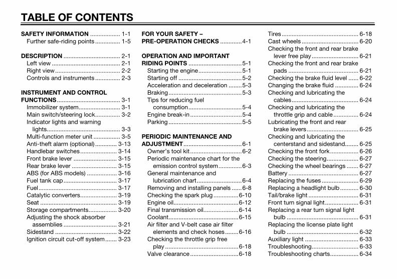
TABLE OF CONTENTS
SAFETY INFORMATION .................. 1-1Further safe-riding points ............... 1-5
DESCRIPTION .................................. 2-1Left view ......................................... 2-1Right view....................................... 2-2Controls and instruments ............... 2-3
INSTRUMENT AND CONTROL
FUNCTIONS ...................................... 3-1Immobilizer system......................... 3-1Main switch/steering lock............... 3-2Indicator lights and warning
lights............................................ 3-3Multi-function meter unit ................ 3-5Anti-theft alarm (optional) ............. 3-13Handlebar switches...................... 3-14Front brake lever .......................... 3-15Rear brake lever ........................... 3-15ABS (for ABS models) .................. 3-16Fuel tank cap................................ 3-17Fuel............................................... 3-17Catalytic converters...................... 3-19Seat .............................................. 3-19Storage compartments................. 3-20Adjusting the shock absorber
assemblies ................................ 3-21Sidestand ..................................... 3-22Ignition circuit cut-off system....... 3-23
FOR YOUR SAFETY –
PRE-OPERATION CHECKS .............4-1
OPERATION AND IMPORTANT
RIDING POINTS ................................5-1Starting the engine..........................5-1Starting off ......................................5-2Acceleration and deceleration ........5-3Braking............................................5-3Tips for reducing fuel
consumption................................5-4Engine break-in ...............................5-4Parking ............................................5-5
PERIODIC MAINTENANCE AND
ADJUSTMENT...................................6-1Owner’s tool kit ...............................6-2Periodic maintenance chart for the
emission control system..............6-3General maintenance and
lubrication chart...........................6-4Removing and installing panels ......6-8Checking the spark plug ...............6-10Engine oil.......................................6-12Final transmission oil.....................6-14Coolant..........................................6-15Air filter and V-belt case air filter
elements and check hoses........6-16Checking the throttle grip free
play ............................................6-18Valve clearance.............................6-18
Tires .............................................. 6-18Cast wheels .................................. 6-20Checking the front and rear brake
lever free play ............................ 6-21Checking the front and rear brake
pads .......................................... 6-21Checking the brake fluid level ...... 6-22Changing the brake fluid .............. 6-24Checking and lubricating the
cables........................................ 6-24Checking and lubricating the
throttle grip and cable ............... 6-24Lubricating the front and rear
brake levers............................... 6-25Checking and lubricating the
centerstand and sidestand........ 6-25Checking the front fork................. 6-26Checking the steering................... 6-27Checking the wheel bearings ....... 6-27Battery .......................................... 6-27Replacing the fuses ...................... 6-29Replacing a headlight bulb ........... 6-30Tail/brake light .............................. 6-31Front turn signal light.................... 6-31Replacing a rear turn signal light
bulb ........................................... 6-31Replacing the license plate light
bulb ........................................... 6-32Auxiliary light ................................ 6-33Troubleshooting............................ 6-33Troubleshooting charts................. 6-34
U2DME1E0.book Page 1 Wednesday, October 23, 2013 1:37 PM

TABLE OF CONTENTS
SCOOTER CARE AND STORAGE ....7-1Matte color caution .........................7-1Care.................................................7-1Storage............................................7-4
SPECIFICATIONS..............................8-1
CONSUMER INFORMATION ............9-1Identification numbers.....................9-1
INDEX...............................................10-1
U2DME1E0.book Page 2 Wednesday, October 23, 2013 1:37 PM

1-1
1
SAFETY INFORMATION
EAU1026B
Be a Responsible Owner
As the vehicle’s owner, you are re-sponsible for the safe and proper oper-ation of your scooter.Scooters are single-track vehicles.Their safe use and operation are de-pendent upon the use of proper ridingtechniques as well as the expertise ofthe operator. Every operator shouldknow the following requirements be-fore riding this scooter.He or she should: Obtain thorough instructions from
a competent source on all aspectsof scooter operation.
Observe the warnings and mainte-nance requirements in this Own-er’s Manual.
Obtain qualified training in safeand proper riding techniques.
Obtain professional technical ser-vice as indicated in this Owner’sManual and/or when made neces-sary by mechanical conditions.
Never operate a scooter withoutproper training or instruction. Takea training course. Beginnersshould receive training from a cer-tified instructor. Contact an autho-rized scooter dealer to find outabout the training courses nearestyou.
Safe Riding
Perform the pre-operation checkseach time you use the vehicle to makesure it is in safe operating condition.Failure to inspect or maintain the vehi-cle properly increases the possibility ofan accident or equipment damage.See page 4-1 for a list of pre-operationchecks. This scooter is designed to carry
the operator and a passenger. The failure of motorists to detect
and recognize scooters in traffic isthe predominating cause of auto-mobile/scooter accidents. Manyaccidents have been caused byan automobile driver who did notsee the scooter. Making yourself
conspicuous appears to be veryeffective in reducing the chance ofthis type of accident.Therefore:
• Wear a brightly colored jacket.• Use extra caution when you are
approaching and passingthrough intersections, since in-tersections are the most likelyplaces for scooter accidents tooccur.
• Ride where other motorists cansee you. Avoid riding in anothermotorist’s blind spot.
• Never maintain a scooter with-out proper knowledge. Contactan authorized scooter dealer toinform you on basic scootermaintenance. Certain mainte-nance can only be carried outby certified staff.
U2DME1E0.book Page 1 Wednesday, October 23, 2013 1:37 PM

SAFETY INFORMATION
1-2
1 Many accidents involve inexperi-
enced operators. In fact, many op-erators who have been involved inaccidents do not even have a cur-rent driver’s license.• Make sure that you are qualified
and that you only lend yourscooter to other qualified opera-tors.
• Know your skills and limits.Staying within your limits mayhelp you to avoid an accident.
• We recommend that you prac-tice riding your scooter wherethere is no traffic until you havebecome thoroughly familiar withthe scooter and all of its con-trols.
Many accidents have beencaused by error of the scooter op-erator. A typical error made by theoperator is veering wide on a turndue to excessive speed or under-cornering (insufficient lean anglefor the speed).• Always obey the speed limit and
never travel faster than warrant-ed by road and traffic condi-tions.
• Always signal before turning orchanging lanes. Make sure thatother motorists can see you.
The posture of the operator andpassenger is important for propercontrol.• The operator should keep both
hands on the handlebar andboth feet on the operator foot-rests during operation to main-tain control of the scooter.
• The passenger should alwayshold onto the operator, the seatstrap or grab bar, if equipped,with both hands and keep bothfeet on the passenger footrests.Never carry a passenger unlesshe or she can firmly place bothfeet on the passenger footrests.
Never ride under the influence ofalcohol or other drugs.
This scooter is designed for on-road use only. It is not suitable foroff-road use.
Protective Apparel
The majority of fatalities from scooteraccidents are the result of head inju-ries. The use of a safety helmet is thesingle most critical factor in the pre-vention or reduction of head injuries. Always wear an approved helmet. Wear a face shield or goggles.
Wind in your unprotected eyescould contribute to an impairmentof vision that could delay seeing ahazard.
The use of a jacket, substantialshoes, trousers, gloves, etc., is ef-fective in preventing or reducingabrasions or lacerations.
Never wear loose-fitting clothes,otherwise they could catch on thecontrol levers or wheels and causeinjury or an accident.
Always wear protective clothingthat covers your legs, ankles, andfeet. The engine or exhaust sys-tem become very hot during or af-ter operation and can causeburns.
A passenger should also observethe above precautions.
U2DME1E0.book Page 2 Wednesday, October 23, 2013 1:37 PM

SAFETY INFORMATION
1-3
1Avoid Carbon Monoxide Poisoning
All engine exhaust contains carbonmonoxide, a deadly gas. Breathingcarbon monoxide can cause head-aches, dizziness, drowsiness, nausea,confusion, and eventually death.Carbon Monoxide is a colorless, odor-less, tasteless gas which may bepresent even if you do not see or smellany engine exhaust. Deadly levels ofcarbon monoxide can collect rapidlyand you can quickly be overcome andunable to save yourself. Also, deadlylevels of carbon monoxide can lingerfor hours or days in enclosed or poorlyventilated areas. If you experience anysymptoms of carbon monoxide poi-soning, leave the area immediately, getfresh air, and SEEK MEDICAL TREAT-MENT. Do not run engine indoors. Even if
you try to ventilate engine exhaustwith fans or open windows anddoors, carbon monoxide can rap-idly reach dangerous levels.
Do not run engine in poorly venti-lated or partially enclosed areassuch as barns, garages, or car-ports.
Do not run engine outdoors whereengine exhaust can be drawn intoa building through openings suchas windows and doors.
Loading
Adding accessories or cargo to yourscooter can adversely affect stabilityand handling if the weight distributionof the scooter is changed. To avoid thepossibility of an accident, use extremecaution when adding cargo or acces-sories to your scooter. Use extra carewhen riding a scooter that has addedcargo or accessories. Here, along withthe information about accessories be-low, are some general guidelines to fol-low if loading cargo to your scooter:The total weight of the operator, pas-senger, accessories and cargo mustnot exceed the maximum load limit.Operation of an overloaded vehicle
could cause an accident.
When loading within this weight limit,keep the following in mind: Cargo and accessory weight
should be kept as low and close tothe scooter as possible. Securelypack your heaviest items as closeto the center of the vehicle as pos-sible and make sure to distributethe weight as evenly as possibleon both sides of the scooter tominimize imbalance or instability.
Shifting weights can create a sud-den imbalance. Make sure thataccessories and cargo are se-curely attached to the scooter be-fore riding. Check accessorymounts and cargo restraints fre-quently.• Properly adjust the suspension
for your load (suspension-ad-justable models only), andcheck the condition and pres-sure of your tires.
• Never attach any large or heavyitems to the handlebar, frontfork, or front fender. Such itemscan create unstable handling ora slow steering response.
Maximum load:YP125R 185 kg (408 lb)YP125RA 181 kg (399 lb)
U2DME1E0.book Page 3 Wednesday, October 23, 2013 1:37 PM

SAFETY INFORMATION
1-4
1 This vehicle is not designed to
pull a trailer or to be attached to
a sidecar.
Genuine Yamaha Accessories
Choosing accessories for your vehicleis an important decision. GenuineYamaha accessories, which are avail-able only from a Yamaha dealer, havebeen designed, tested, and approvedby Yamaha for use on your vehicle.Many companies with no connectionto Yamaha manufacture parts and ac-cessories or offer other modificationsfor Yamaha vehicles. Yamaha is not ina position to test the products thatthese aftermarket companies produce.Therefore, Yamaha can neither en-dorse nor recommend the use of ac-cessories not sold by Yamaha ormodifications not specifically recom-mended by Yamaha, even if sold andinstalled by a Yamaha dealer.
Aftermarket Parts, Accessories, and
Modifications
While you may find aftermarket prod-ucts similar in design and quality togenuine Yamaha accessories, recog-
nize that some aftermarket accesso-ries or modifications are not suitablebecause of potential safety hazards toyou or others. Installing aftermarketproducts or having other modificationsperformed to your vehicle that changeany of the vehicle’s design or operationcharacteristics can put you and othersat greater risk of serious injury ordeath. You are responsible for injuriesrelated to changes in the vehicle.Keep the following guidelines in mind,as well as those provided under “Load-ing” when mounting accessories. Never install accessories or carry
cargo that would impair the per-formance of your scooter. Careful-ly inspect the accessory beforeusing it to make sure that it doesnot in any way reduce groundclearance or cornering clearance,limit suspension travel, steeringtravel or control operation, or ob-scure lights or reflectors.• Accessories fitted to the han-
dlebar or the front fork area cancreate instability due to improp-er weight distribution or aerody-namic changes. If accessories
are added to the handlebar orfront fork area, they must be aslightweight as possible andshould be kept to a minimum.
• Bulky or large accessories mayseriously affect the stability ofthe scooter due to aerodynamiceffects. Wind may attempt to liftthe scooter, or the scooter maybecome unstable in crosswinds. These accessories mayalso cause instability whenpassing or being passed bylarge vehicles.
• Certain accessories can dis-place the operator from his orher normal riding position. Thisimproper position limits thefreedom of movement of theoperator and may limit controlability, therefore, such accesso-ries are not recommended.
Use caution when adding electri-cal accessories. If electrical ac-cessories exceed the capacity ofthe scooter’s electrical system, anelectric failure could result, whichcould cause a dangerous loss oflights or engine power.
U2DME1E0.book Page 4 Wednesday, October 23, 2013 1:37 PM

SAFETY INFORMATION
1-5
1Aftermarket Tires and Rims
The tires and rims that came with yourscooter were designed to match theperformance capabilities and to pro-vide the best combination of handling,braking, and comfort. Other tires, rims,sizes, and combinations may not beappropriate. Refer to page 6-18 for tirespecifications and more information onreplacing your tires.
Transporting the Scooter
Be sure to observe following instruc-tions before transporting the scooter inanother vehicle. Remove all loose items from the
scooter. Point the front wheel straight
ahead on the trailer or in the truckbed, and choke it in a rail to pre-vent movement.
Secure the scooter with tie-downsor suitable straps that are at-tached to solid parts of the scoot-er, such as the frame or upperfront fork triple clamp (and not, forexample, to rubber-mounted han-dlebars or turn signals, or partsthat could break). Choose the lo-
cation for the straps carefully sothe straps will not rub againstpainted surfaces during transport.
The suspension should be com-pressed somewhat by the tie-downs, if possible, so that thescooter will not bounce exces-sively during transport.
EAU57600
Further safe-riding points Be sure to signal clearly when
making turns. Braking can be extremely difficult
on a wet road. Avoid hard braking,because the scooter could slide.Apply the brakes slowly whenstopping on a wet surface.
Slow down as you approach acorner or turn. Once you havecompleted a turn, accelerateslowly.
Be careful when passing parkedcars. A driver might not see youand open a door in your path.
Railroad crossings, streetcar rails,iron plates on road constructionsites, and manhole covers be-come extremely slippery whenwet. Slow down and cross themwith caution. Keep the scooter up-right, otherwise it could slide outfrom under you.
The brake pads or linings couldget wet when you wash the scoot-er. After washing the scooter,check the brakes before riding.
U2DME1E0.book Page 5 Wednesday, October 23, 2013 1:37 PM

SAFETY INFORMATION
1-6
1 Always wear a helmet, gloves,
trousers (tapered around the cuffand ankle so they do not flap), anda brightly colored jacket.
Do not carry too much luggage onthe scooter. An overloaded scoot-er is unstable. Use a strong cordto secure any luggage to the carri-er (if equipped). A loose load willaffect the stability of the scooterand could divert your attentionfrom the road. (See page 1-3.)
U2DME1E0.book Page 6 Wednesday, October 23, 2013 1:37 PM

DESCRIPTION
2-1
2
EAU10411
Left view
1 52 43 76
9 8 1011121. Headlight (page 6-30)2. Battery (page 6-27)3. Main fuse (page 6-29)4. Coolant reservoir cap (page 6-15)5. Coolant level check window (page 6-15)6. Rear storage compartment (page 3-20)7. V-belt case air filter element (page 6-16)8. Shock absorber assembly spring preload adjusting ring (page 3-21)
9. Air filter element (left) (page 6-16)10.Engine oil filter element (page 6-12)11.Sidestand (page 3-22)12.Front brake pads (page 6-21)
U2DME1E0.book Page 1 Wednesday, October 23, 2013 1:37 PM
DESCRIPTION
2-2
2
EAU10421
Right view
6 5
1 2 43
1. Grab bar (page 5-2)2. Seat (page 3-19)3. Fuel tank cap (page 3-17)4. Fuses (page 6-29)5. Centerstand (page 6-25)6. Shock absorber assembly spring preload adjusting ring (page 3-21)
U2DME1E0.book Page 2 Wednesday, October 23, 2013 1:37 PM

DESCRIPTION
2-3
2
EAU10431
Controls and instruments
98
765
4
3
2
1
11
10
12
0
1000r/minx
E F C H
F
SELECT RESET
41 753 62
891011121. Rear brake lever (page 3-15)2. Left handlebar switches (page 3-14)3. Speedometer4. Warning and indicator light (page 3-3)5. Multi-function display (page 3-5)6. Right handlebar switches (page 3-14)7. Front brake lever (page 3-15)8. Throttle grip (page 6-18)
9. Front storage compartment B (page 3-20)10.Main switch/steering lock (page 3-2)11.Coolant level check window (page 6-15)12.Front storage compartment A (page 3-20)
U2DME1E0.book Page 3 Wednesday, October 23, 2013 1:37 PM

INSTRUMENT AND CONTROL FUNCTIONS
3-1
3
EAU10978
Immobilizer system
This vehicle is equipped with an immo-bilizer system to help prevent theft byre-registering codes in the standardkeys. This system consists of the fol-lowing: a code re-registering key (with a
red bow) two standard keys (with a black
bow) that can be re-registeredwith new codes
a transponder (which is installed inthe code re-registering key)
an immobilizer unit an ECU
an immobilizer system indicatorlight (See page 3-5.)
The key with the red bow is used toregister codes in each standard key.Since re-registering is a difficult pro-cess, take the vehicle along with allthree keys to a Yamaha dealer to havethem re-registered. Do not use the keywith the red bow for driving. It shouldonly be used for re-registering thestandard keys. Always use a standardkey for driving.
NOTICEECA11822
DO NOT LOSE THE CODE RE-
REGISTERING KEY! CONTACT
YOUR DEALER IMMEDIATELY
IF IT IS LOST! If the code re-reg-
istering key is lost, registering
new codes in the standard keys
is impossible. The standard
keys can still be used to start
the vehicle, however if code re-
registering is required (i.e., if a
new standard key is made or all
keys are lost) the entire immobi-
lizer system must be replaced.
Therefore, it is highly recom-
mended to use either standard
key and keep the code re-regis-
tering key in a safe place.
Do not submerse any key in wa-
ter.
Do not expose any key to exces-
sively high temperatures.
Do not place any key close to
magnets (this includes, but not
limited to, products such as
speakers, etc.).
Do not place items that transmit
electrical signals close to any
key.
Do not place heavy items on any
key.
Do not grind any key or alter its
shape.
Do not disassemble the plastic
part of any key.
Do not put two keys of any im-
mobilizer system on the same
key ring.
Keep the standard keys as well
as keys of other immobilizer
systems away from this vehi-
cle’s code re-registering key.
1. Code re-registering key (red bow)2. Standard keys (black bow)
U2DME1E0.book Page 1 Wednesday, October 23, 2013 1:37 PM

INSTRUMENT AND CONTROL FUNCTIONS
3-2
3
Keep other immobilizer system
keys away from the main switch
as they may cause signal inter-
ference.
EAU10473
Main switch/steering lock
The main switch/steering lock controlsthe ignition and lighting systems, and isused to lock the steering. The variouspositions are described below.
TIP
Be sure to use the standard key (blackbow) for regular use of the vehicle. Tominimize the risk of losing the code re-registering key (red bow), keep it in asafe place and only use it for code re-registering.
EAU34122
ON
All electrical circuits are supplied withpower; the meter lighting, taillight, li-cense plate light and auxiliary lightscome on, and the engine can be start-ed. The key cannot be removed.
TIP
The headlights come on automaticallywhen the engine is started and stay onuntil the key is turned to “OFF” or thesidestand is moved down.
EAU10662
OFF
All electrical systems are off. The keycan be removed.
WARNING
EWA10062
Never turn the key to “OFF” or
“LOCK” while the vehicle is moving.
Otherwise the electrical systems will
be switched off, which may result in
loss of control or an accident.
ZAUM1004
U2DME1E0.book Page 2 Wednesday, October 23, 2013 1:37 PM

INSTRUMENT AND CONTROL FUNCTIONS
3-3
3
EAU10685
LOCK
The steering is locked, and all electricalsystems are off. The key can be re-moved.
To lock the steering1. Turn the handlebars all the way to
the left.2. Push the key in from the “OFF”
position, and then turn it to“LOCK” while still pushing it.
3. Remove the key.
To unlock the steeringPush the key in, and then turn it to“OFF” while still pushing it.
EAUM2971
(Parking)
The hazard lights and turn signal lightscan be turned on, but all other electri-cal systems are off. The key can be re-moved.The steering must be locked before thekey can be turned to “ ”.
NOTICEECA11021
Do not use the parking position for
an extended length of time, other-
wise the battery may discharge.
EAU49395
Indicator lights and warning lights
EAU11031
Turn signal indicator lights “ ”
and “ ”
The corresponding indicator lightflashes when the turn signal switch ispushed to the left or right.
1. Turn signal indicator lights “ ” and “ ”2. High beam indicator light “ ”3. Engine trouble warning light “ ”4. Fuel level warning light “ ”5. Immobilizer system indicator light “ ”6. Anti-lock Brake System (ABS) warning
light “ ” (for ABS models)
ZAUM1098
2 3 4 5 6
98
765
4
3
2
1
11
10
12
0
1000r/minx
km/h
E F C H
km
OdoOdo
SELECT RESET
11
ABS
U2DME1E0.book Page 3 Wednesday, October 23, 2013 1:37 PM

INSTRUMENT AND CONTROL FUNCTIONS
3-4
3
EAU11081
High beam indicator light “ ”
This indicator light comes on when thehigh beam of the headlight is switchedon.
EAU11354
Fuel level warning light “ ”
This warning light comes on when thefuel level drops below approximately2.5 L (0.66 US gal, 0.55 Imp.gal). Whenthis occurs, refuel as soon as possible.The electrical circuit of the warninglight can be checked by turning the keyto “ON”. The warning light shouldcome on for a few seconds, and thengo off.If the warning light does not come oninitially when the key is turned to “ON”,or if the warning light remains on, havea Yamaha dealer check the electricalcircuit.
EAU43024
Engine trouble warning light “ ”
This warning light comes on if an elec-trical circuit monitoring the engine isnot working correctly. If this occurs,have a Yamaha dealer check the self-diagnosis system.
The electrical circuit of the warninglight can be checked by turning the keyto “ON”. The warning light shouldcome on for a few seconds, and thengo off.If the warning light does not come oninitially when the key is turned to “ON”,or if the warning light remains on, havea Yamaha dealer check the electricalcircuit.
TIP
This warning light will come on whenthe key is turned to “ON” and the startswitch is pushed, but this does not in-dicate a malfunction.
EAUM3381
ABS warning light “ ” (for ABS
models)
In normal operation, the ABS warninglight comes on when the key is turnedto “ON”, and goes off after traveling ata speed of 10 km/h (6 mi/h) or higher.If the ABS warning light: does not come on when the key is
turned to “ON” comes on or flashes while riding
does not go off after traveling at aspeed of 10 km/h (6 mi/h) or high-er
The ABS may not work correctly. If anyof the above occurs, have a Yamahadealer check the system as soon aspossible. (See page 3-16 for an expla-nation of the ABS.)
WARNING
EWA16041
If the ABS warning light does not go
off after traveling at a speed of 10
km/h (6 mi/h) or higher, or if the
warning light comes on or flashes
while riding, the brake system re-
verts to conventional braking. If ei-
ther of the above occurs, or if the
warning light does not come on at
all, use extra caution to avoid possi-
ble wheel lock during emergency
braking. Have a Yamaha dealer
check the brake system and electri-
cal circuits as soon as possible.
ABS
U2DME1E0.book Page 4 Wednesday, October 23, 2013 1:37 PM

INSTRUMENT AND CONTROL FUNCTIONS
3-5
3
TIP
The ABS warning light may come onwhile accelerating the engine with thescooter on its centerstand, but thisdoes not indicate a malfunction.
EAU26878
Immobilizer system indicator
light “ ”
The electrical circuit of the indicatorlight can be checked by turning the keyto “ON”. The indicator light shouldcome on for a few seconds, and thengo off.If the indicator light does not come oninitially when the key is turned to “ON”,or if the indicator light remains on, havea Yamaha dealer check the electricalcircuit.When the key is turned to “OFF” and30 seconds have passed, the indicatorlight will start flashing indicating the im-mobilizer system is enabled. After 24hours have passed, the indicator lightwill stop flashing, however the immobi-lizer system is still enabled.
The self-diagnosis device also detectsproblems in the immobilizer systemcircuits. (See page 3-12 for an expla-nation of the self-diagnosis device.)
EAUM3313
Multi-function meter unit
WARNING
EWA12423
Be sure to stop the vehicle before
making any setting changes to the
multi-function meter unit. Changing
settings while riding can distract the
operator and increase the risk of an
accident.
1. Tachometer2. Speedometer3. “SELECT” button4. “RESET” button5. Multi-function display6. Clock7. Fuel meter8. “TRIP/INFO” switch9. Coolant temperature display
ZAUM1099
3
98
765
4
3
2
1
11
10
12
0
1000r/minx
km/h
E F C H
km
Odo
AirAveCons
Oil V-BeltTimeTripOdo
SELECT RESET
F
4 65
7
21
8 9INFO
TRIP
U2DME1E0.book Page 5 Wednesday, October 23, 2013 1:37 PM

INSTRUMENT AND CONTROL FUNCTIONS
3-6
3
The multi-function meter unit isequipped with the following: a speedometer a tachometer a fuel meter a clock an odometer and tripmeter display a multi-function display a coolant temperature meter
TIP
Be sure to turn the key to “ON” be-fore using the “Select”, “Reset”,“TRIP” and “INFO” buttons.
When the key is turned to “ON”, alldisplay segments of the multi-function meter unit will momen-tarily appear in order to test theelectrical circuit. The speedome-ter and odometer will then performa display check and a welcomemessage will scroll across themulti-function display.
For the UK, traveling speed, dis-tance traveled, and fuel consump-tion measurements can bedisplayed in kilometer or mileagebased units. To switch betweenmiles and kilometers; hold the
“SELECT” switch pushed, turn themain switch to “ON”, and keep the“SELECT” switch pushed for anadditional 8 seconds.
For other countries, travelingspeed, distance traveled and fuelconsumption measurements aredisplayed in kilometer base units.
Speedometer
The speedometer shows the ridingspeed.
Tachometer
The electric tachometer allows the rid-er to monitor the engine speed andkeep it within the ideal power range.
NOTICEECAM1150
Do not operate the engine in the ta-
chometer high-rpm zone.
High-rpm zone: 10000 r/min and
above
Fuel meter
With the key in the “ON” position, thefuel meter indicates the amount of fuelin the fuel tank. The display segmentsof the fuel meter disappear towards“E” (Empty) as the fuel level decreases.When the fuel level reaches the bottomsegment near “E”, the bottom segmentwill flash. Refuel as soon as possible.
1. Tachometer2. High-rpm zone
ZAUM1101
19
876
54
3
2
1
11
10
12
0
1000r/minx
km/h
E F
2 1. Fuel meter2. Fuel level warning indicator “ ”3. Fuel reserve tripmeter
ZAUM1102
98
765
4
3
2
1
11
10
12
0
1000r/min
km/h
E F C H
km
TripOdo
SELECT RESET
F
31 2
U2DME1E0.book Page 6 Wednesday, October 23, 2013 1:37 PM

INSTRUMENT AND CONTROL FUNCTIONS
3-7
3
Clock
To set the clock:1. Push the “SELECT” button for 3
seconds, and the hour digits willstart flashing.
2. Use the “SELECT” button to setthe hours.
3. Push the “SELECT” button for 3seconds, and the minute digits willstart flashing.
4. Use the “SELECT” button to setthe minutes.
5. Push the “SELECT” button for 3seconds to complete setting theclock.
Odometer and tripmeter display
The odometer and tripmeter display isequipped with the following: a tripmeter (which shows the dis-
tance traveled since last set to ze-ro)
a time tripmeter (which shows theelapsed riding time since last setto zero)
a fuel reserve tripmeter (whichshows the distance traveled sincethe fuel level warning light cameon)
an oil change tripmeter (whichshows the distance traveled sincethe last engine oil change)
a V-belt replacement tripmeter(which shows the distance trav-eled since the last V-belt replace-ment)
Pushing the “TRIP” button switchesthe display between the odometermode and the various tripmeter modesin the following order:Odo (odometer) → Trip (tripmeter) →Trip Time (time tripmeter) → Oil (oilchange tripmeter) → V-Belt (v-belt re-placement tripmeter) → Odo (odome-ter)When approximately 2.5 L (0.66 USgal, 0.55 Imp.gal) of fuel remains in thefuel tank, the display will automaticallychange to the fuel reserve tripmetermode “F Trip” and start counting thedistance traveled from that point. Inthat case, pushing the “TRIP” buttonswitches the display between the vari-ous tripmeter and odometer modes inthe following order:Odo → Trip → Trip Time → F Trip (fuelreserve tripmeter) → Oil Trip → V-BeltTrip → Odo
1. “TRIP/INFO” switch2. Function display
ZAUM1104
C H
km
Odo
Air
Oil V-BeltTimeTripOdoF
21
INFO
TRIP
U2DME1E0.book Page 7 Wednesday, October 23, 2013 1:37 PM

INSTRUMENT AND CONTROL FUNCTIONS
3-8
3
Oil Trip and V-Belt Trip display totaldistance traveled from the first run orwhen the last reset was done.To reset a tripmeter, select it by push-ing the “TRIP” button until “Trip, TripTime, F Trip” is displayed. While “Trip,Trip Time, F Trip” is displayed, pushthe “TRIP” button for 3 seconds. If youdo not reset the fuel reserve tripmetermanually, it will reset itself automatical-ly and the display will return to the priormode after refueling and traveling 5 km(3 mi).
TIP
The display cannot be changed backto “F Trip” after it has been reset.
Oil change indicator “Oil”
This indicator flashes at the initial 1000km (600 mi), then at 5000 km (3000 mi)and every 6000 km (3500 mi) thereafterto indicate that the engine oil should bechanged.After changing the engine oil, reset theoil change indicator.
To reset the oil change indicator
1. Turn the key to “ON”.
2. Push the “TRIP” button until “Oil”(oil change tripmeter) is displayedin the odometer and trip meterdisplay. While “Oil” is displayed,push the “RESET” button for atleast 3 seconds. The oil changetripmeter value will flash.
3. Hold the “RESET” button pushedfor 15 to 20 seconds.
4. Release the “RESET” button, andthe oil trip value will reset to zero.
TIP
If the engine oil is changed before theoil change indicator comes on (i.e. be-fore the periodic oil change interval hasbeen reached), the indicator must bereset after the oil change for the nextperiodic oil change to be indicated atthe correct time. To reset the oilchange indicator before the periodic oilchange interval has been reached, fol-low the above procedure.
The electrical circuit of the indicatorcan be checked according to the fol-lowing procedure.
1. Turn the key to “ON”.
1. “TRIP/INFO” switch2. “RESET” button
ZAUM1121
C H
km
Air
OilOdo
1
INFO
TRIP
2
SELECT RESET
km1. “RESET” button
ZAUM1122
C H
km
Air
OilOdo
SELECT RESET
km
Oil
1
U2DME1E0.book Page 8 Wednesday, October 23, 2013 1:37 PM

INSTRUMENT AND CONTROL FUNCTIONS
3-9
3
2. Check that the oil change indica-tor comes on for a few secondsand then goes off.
3. If the oil change indicator does notcome on, have a Yamaha dealercheck the electrical circuit.
V-belt replacement indicator “V-
Belt”
This indicator flashes every 18000 km(10500 mi) when the V-belt needs to bereplaced.After changing the V-belt, reset the V-belt replacement indicator.
To reset the V-belt replacement indi-
cator
1. Turn the key to “ON”.2. Push the “TRIP” button until “V-
belt” (V-belt replacement tripme-ter) is displayed in the odometerand trip meter display. While “V-belt” is displayed, push the “RE-SET” button for 3 seconds. The V-belt replacement tripmeter valuewill flash.
3. Hold the “RESET” button pushedfor 15 to 20 seconds.
4. Release the “RESET” button, andthe V-belt trip value will reset tozero.
TIP
If the V-belt is replaced before the indi-cator comes on, be sure to reset the V-belt replacement indicator so that it willcome on at the next correct interval.
The electrical circuit of the indicatorcan be checked according to the fol-lowing procedure.
1. Turn the key to “ON”.2. Check that the V-belt replacement
indicator comes on for a few sec-onds and then goes off.
3. If the V-belt replacement indicatordoes not come on, have a Yamahadealer check the electrical circuit.
1. “TRIP/INFO” switch2. “RESET” button
1. “RESET” button
ZAUM1137
C H
km
Air
Odo
1
INFO
TRIP
2
SELECT RESET
V-Belt
ZAUM1138
C H
km
Air
Odo
SELECT RESET
km
1
V-Belt
V-Belt
U2DME1E0.book Page 9 Wednesday, October 23, 2013 1:37 PM

INSTRUMENT AND CONTROL FUNCTIONS
3-10
3
Multi-function display
The multi-function display is equippedwith the following: an ambient temperature display a battery voltage level display a fuel consumption display (aver-
age and instantaneous consump-tion functions)
an average speed display (whichshows the average speed sincelast set to zero)
a warning message function
a self-diagnosis device
Push the “INFO” button to switch thedisplay between the ambient tempera-ture display “Air”, the battery voltage,the average fuel consumption mode“Ave/Cons__._km/L” or “Ave/Cons__._ L/100 km”, the instantaneous fuelconsumption mode “Cons__._km/L”or “Cons__._L/100 km”, and the aver-age speed “Ave” in the following order:
Air → → Ave/Cons_ _._ km/L orL/100 km → Cons__._km/L or L/100km → Ave → Air
For the UK only:Push the “INFO” button to switch thedisplay between the ambient tempera-ture display “Air”, the battery voltage,the average fuel consumption mode“Ave/Cons__._ MPG”, the instanta-neous fuel consumption mode“Cons__._MPG”, and the averagespeed “Ave” in the following order:
Air → → Ave/Cons_ _._ MPG →Cons__._MPG → Ave → Air
Ambient temperature display
This display shows the ambient tem-perature from –10 °C to 50 °C in 1 °Cincrements.The icy road warning indicator “ ” willflash when the temperature is below4°C.The temperature displayed may varyfrom the ambient temperature. Push-ing the “INFO” button switches theambient temperature display to thebattery voltage, the average fuel con-sumption, the instantaneous fuel con-sumption and average speed modes.
1. Ambient temperature2. Average speed3. Instantaneous fuel consumption4. Average fuel consumption5. Icy road warning indicator “ ”6. Battery voltage7. “TRIP/INFO” switch
ZAUM1107
C H
Air
AveCons
123
45 6 7 INFO
TRIP
AveCons
ZAUM1108
C H
km
Trip
U2DME1E0.book Page 10 Wednesday, October 23, 2013 1:37 PM
INSTRUMENT AND CONTROL FUNCTIONS
3-11
3
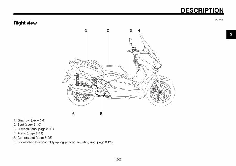
Battery voltage level display
This display shows the battery voltagefrom 10.1 Volt to 17.9 Volt in 0.1 V in-crements.
The voltage displayed may vary fromthe battery voltage. Pushing the “IN-FO” button switches the ambient tem-perature display to the battery voltage,the average fuel consumption, the in-stantaneous fuel consumption and av-erage speed modes.
TIP
If the battery warning indicator “ ”flash and warning message indicate “HBATT” or “L BATT”, have a Yamahadealer check the battery.
Average fuel consumption mode
The average fuel consumption displaycan be set to either “Ave/Cons_ _._km/L” or “Ave/Cons_ _._ L/100 km”(except for the UK).
For the UK only:The average fuel consumption is dis-played “Ave/Cons_ _._ MPG”.This display shows the average fuelconsumption since it was last reset. When the display is set to
“Ave/Cons_ _._ km/L”, the aver-age distance that can be traveledon 1.0 L of fuel is shown.
When the display is set to“Ave/Cons_ _._ L/100 km”, the av-erage amount of fuel necessary totravel 100 km is shown.
For the UK only: When the displayis set to “Ave/Cons_ _._ MPG”,the average distance that can betraveled on 1.0 Imp.gal of fuel isshown.
To reset the average fuel consumptiondisplay, select it by pushing the “INFO”button, and then push and hold the“INFO” button for 3 seconds.
TIP
After resetting an average fuel con-sumption display, “_ _._” is shown forthat display until the vehicle has trav-eled 1 km (0.6 mi).
Instantaneous fuel consumption mode
ZAUM1109
C H
km
Trip
ZAUM1110
C H
km
L/100km
Cons
Oil
km/L
ZAUM1111
C H
km
L/100km
Cons
Oil
km/L
U2DME1E0.book Page 11 Wednesday, October 23, 2013 1:37 PM
INSTRUMENT AND CONTROL FUNCTIONS
3-12
3
The instantaneous fuel consumptiondisplay can be set to either “km/L” or“L/100 km” (except for the UK).
For the UK only:The instantaneous fuel consumption isdisplayed “MPG”.
When the display is set to “km/L”,the distance that can be traveledon 1.0 L of fuel under the currentriding conditions is shown.
When the display is set to “L/100km”, the amount of fuel necessaryto travel 100 km under the currentriding conditions is shown.
For the UK only: The distance thatcan be traveled on 1.0 Imp.gal offuel under the current riding condi-tions is shown.
To switch between the instantaneousfuel consumption displays, push the“INFO” button for less than one sec-ond when one of the displays is shown(except for the UK).
TIP
If traveling at speeds under 10 km/h(6.0 mi/h), “_ _._” is displayed.
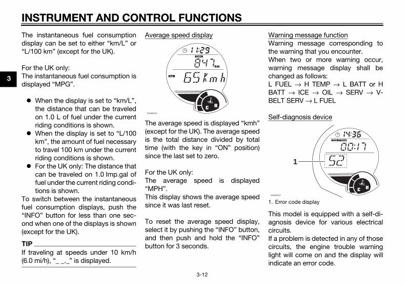
Average speed display
The average speed is displayed “kmh”(except for the UK). The average speedis the total distance divided by totaltime (with the key in “ON” position)since the last set to zero.
For the UK only:The average speed is displayed“MPH”.This display shows the average speedsince it was last reset.
To reset the average speed display,select it by pushing the “INFO” button,and then push and hold the “INFO”button for 3 seconds.
Warning message functionWarning message corresponding tothe warning that you encounter.When two or more warning occur,warning message display shall bechanged as follows:L FUEL → H TEMP → L BATT or HBATT → ICE → OIL → SERV → V-BELT SERV → L FUEL
Self-diagnosis device
This model is equipped with a self-di-agnosis device for various electricalcircuits.If a problem is detected in any of thosecircuits, the engine trouble warninglight will come on and the display willindicate an error code.
ZAUM1112
C H
km
Odo
AveCons
V-BeltF
1. Error code displayZAUM1114
Trip
C H
Time
1
U2DME1E0.book Page 12 Wednesday, October 23, 2013 1:37 PM

INSTRUMENT AND CONTROL FUNCTIONS
3-13
3
If the display indicates any error codes,note the code number, and then havea Yamaha dealer check the vehicle.
Coolant temperature meter
With the key in the “ON” position, thecoolant temperature meter indicatesthe temperature of the coolant. Thecoolant temperature varies withchanges in the weather and engineload. If the top segment and coolanttemperature warning indicator flash,stop the vehicle and let the enginecool.
NOTICEECA10022
Do not continue to operate the en-
gine if it is overheating.
EAU12332
Anti-theft alarm (optional)This model can be equipped with anoptional anti-theft alarm by a Yamahadealer. Contact a Yamaha dealer formore information.
1. Coolant temperature meter
ZAUM1115 1C H
km
Trip
U2DME1E0.book Page 13 Wednesday, October 23, 2013 1:37 PM
INSTRUMENT AND CONTROL FUNCTIONS
3-14
3
EAU1234F
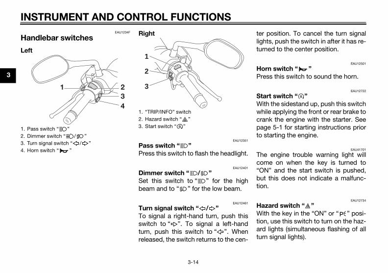
Handlebar switches
Left
Right
EAU12351
Pass switch “ ”
Press this switch to flash the headlight.
EAU12401
Dimmer switch “ / ”
Set this switch to “ ” for the highbeam and to “ ” for the low beam.
EAU12461
Turn signal switch “ / ”
To signal a right-hand turn, push thisswitch to “ ”. To signal a left-handturn, push this switch to “ ”. Whenreleased, the switch returns to the cen-
ter position. To cancel the turn signallights, push the switch in after it has re-turned to the center position.
EAU12501
Horn switch “ ”
Press this switch to sound the horn.
EAU12722
Start switch “ ”
With the sidestand up, push this switchwhile applying the front or rear brake tocrank the engine with the starter. Seepage 5-1 for starting instructions priorto starting the engine.
EAU41701
The engine trouble warning light willcome on when the key is turned to“ON” and the start switch is pushed,but this does not indicate a malfunc-tion.
EAU12734
Hazard switch “ ”
With the key in the “ON” or “ ” posi-tion, use this switch to turn on the haz-ard lights (simultaneous flashing of allturn signal lights).
1. Pass switch “ ”2. Dimmer switch “ / ”3. Turn signal switch “ / ”4. Horn switch “ ”
1. “TRIP/INFO” switch2. Hazard switch “ ”3. Start switch “ ”
INFO
TRIP
1
3
2
U2DME1E0.book Page 14 Wednesday, October 23, 2013 1:37 PM

INSTRUMENT AND CONTROL FUNCTIONS
3-15
3
The hazard lights are used in case of anemergency or to warn other driverswhen your vehicle is stopped where itmight be a traffic hazard.
NOTICEECA10062
Do not use the hazard lights for an
extended length of time with the en-
gine not running, otherwise the bat-
tery may discharge.
EAU12902
Front brake lever
The front brake lever is located on theright side of the handlebar. To applythe front brake, pull this lever towardthe throttle grip.
EAU12952
Rear brake lever
The rear brake lever is located on theleft side of the handlebar. To apply therear brake, pull this lever toward thehandlebar grip.
1. Front brake lever 1. Rear brake lever
U2DME1E0.book Page 15 Wednesday, October 23, 2013 1:37 PM
INSTRUMENT AND CONTROL FUNCTIONS
3-16
3
EAU54001
ABS (for ABS models)The Yamaha ABS (Anti-lock BrakeSystem) features a dual electronic con-trol system, which acts on the front andrear brakes independently.Operate the brakes with ABS as youwould conventional brakes. If the ABSis activated, a pulsating sensation maybe felt at the brake levers. In this situa-tion, continue to apply the brakes andlet the ABS work; do not “pump” thebrakes as this will reduce braking ef-fectiveness.
WARNING
EWA16051
Always keep a sufficient distance
from the vehicle ahead to match the
riding speed even with ABS.
The ABS performs best with
long braking distances.
On certain surfaces, such as
rough or gravel roads, the brak-
ing distance may be longer with
the ABS than without.
The ABS is monitored by an ECU,which will revert the system to conven-tional braking if a malfunction occurs.
TIP
The ABS performs a self-diagno-sis test each time the vehicle firststarts off after the key is turned to“ON” and the vehicle has traveledat a speed of 10 km/h (6 mi/h) orhigher. During this test, a “click-ing” noise can be heard from thefront of the vehicle, and if eitherbrake lever is even slightly ap-plied, a vibration can be felt at thelever, but these do not indicate amalfunction.
This ABS has a test mode whichallows the owner to experiencethe pulsation at the brake leverswhen the ABS is operating. How-ever, special tools are required, soplease consult your Yamaha deal-er when performing this test.
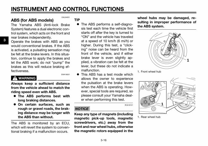
NOTICEECA16121
Keep any type of magnets (including
magnetic pick-up tools, magnetic
screwdrivers, etc.) away from the
front and rear wheel hubs, otherwise
the magnetic rotors equipped in the
wheel hubs may be damaged, re-
sulting in improper performance of
the ABS system.
1. Front wheel hub
1. Rear wheel hub
1
1
U2DME1E0.book Page 16 Wednesday, October 23, 2013 1:37 PM
INSTRUMENT AND CONTROL FUNCTIONS
3-17
3
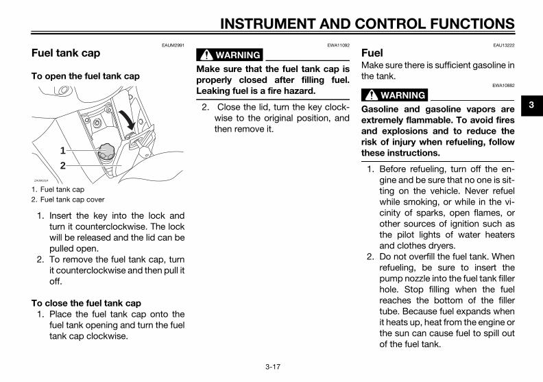
EAUM2991
Fuel tank cap
To open the fuel tank cap
1. Insert the key into the lock andturn it counterclockwise. The lockwill be released and the lid can bepulled open.
2. To remove the fuel tank cap, turnit counterclockwise and then pull itoff.
To close the fuel tank cap
1. Place the fuel tank cap onto thefuel tank opening and turn the fueltank cap clockwise.
WARNING
EWA11092
Make sure that the fuel tank cap is
properly closed after filling fuel.
Leaking fuel is a fire hazard.
2. Close the lid, turn the key clock-wise to the original position, andthen remove it.
EAU13222
FuelMake sure there is sufficient gasoline inthe tank.
WARNING
EWA10882
Gasoline and gasoline vapors are
extremely flammable. To avoid fires
and explosions and to reduce the
risk of injury when refueling, follow
these instructions.
1. Before refueling, turn off the en-gine and be sure that no one is sit-ting on the vehicle. Never refuelwhile smoking, or while in the vi-cinity of sparks, open flames, orother sources of ignition such asthe pilot lights of water heatersand clothes dryers.
2. Do not overfill the fuel tank. Whenrefueling, be sure to insert thepump nozzle into the fuel tank fillerhole. Stop filling when the fuelreaches the bottom of the fillertube. Because fuel expands whenit heats up, heat from the engine orthe sun can cause fuel to spill outof the fuel tank.
1. Fuel tank cap2. Fuel tank cap cover
ZAUM1014
1
2
U2DME1E0.book Page 17 Wednesday, October 23, 2013 1:37 PM

INSTRUMENT AND CONTROL FUNCTIONS
3-18
3
3. Wipe up any spilled fuel immedi-ately. NOTICE: Immediately
wipe off spilled fuel with a clean,
dry, soft cloth, since fuel may
deteriorate painted surfaces or
plastic parts. [ECA10072]
4. Be sure to securely close the fueltank cap.
WARNING
EWA15152
Gasoline is poisonous and can
cause injury or death. Handle gaso-
line with care. Never siphon gasoline
by mouth. If you should swallow
some gasoline or inhale a lot of gas-
oline vapor, or get some gasoline in
your eyes, see your doctor immedi-
ately. If gasoline spills on your skin,
wash with soap and water. If gaso-
line spills on your clothing, change
your clothes.
EAU54601
NOTICEECA11401
Use only unleaded gasoline. The use
of leaded gasoline will cause severe
damage to internal engine parts,
such as the valves and piston rings,
as well as to the exhaust system.
Your Yamaha engine has been de-signed to use premium unleaded gas-oline with a research octane number of95 or higher. If knocking (or pinging)occurs, use a gasoline of a different
brand. Use of unleaded fuel will extendspark plug life and reduce mainte-nance costs.Gasohol
There are two types of gasohol: gaso-hol containing ethanol and that con-taining methanol. Gasohol containingethanol can be used if the ethanol con-tent does not exceed 10% (E10). Gas-ohol containing methanol is notrecommended by Yamaha because itcan cause damage to the fuel systemor vehicle performance problems.
1. Fuel tank filler tube2. Maximum fuel level
ZAUM1015
1
2 Recommended fuel:Premium unleaded gasoline (Gaso-hol (E10) acceptable)
Fuel tank capacity:13.2 L (3.49 US gal, 2.90 Imp.gal)
Fuel reserve amount (when the fuel level warning light comes on):
2.5 L (0.66 US gal, 0.55 Imp.gal)
U2DME1E0.book Page 18 Wednesday, October 23, 2013 1:37 PM

INSTRUMENT AND CONTROL FUNCTIONS
3-19
3
EAU13446
Catalytic convertersThis vehicle is equipped with catalyticconverters in the exhaust system.
WARNING
EWA10863
The exhaust system is hot after op-
eration. To prevent a fire hazard or
burns:
Do not park the vehicle near
possible fire hazards such as
grass or other materials that
easily burn.
Park the vehicle in a place
where pedestrians or children
are not likely to touch the hot
exhaust system.
Make sure that the exhaust sys-
tem has cooled down before
doing any maintenance work.
Do not allow the engine to idle
more than a few minutes. Long
idling can cause a build-up of
heat.
NOTICEECA10702
Use only unleaded gasoline. The use
of leaded gasoline will cause unre-
pairable damage to the catalytic
converter.
EAU13933
Seat
To open the seat
1. Place the scooter on the center-stand.
2. Insert the key into the main switch,and then turn it counterclockwiseto “OPEN”.
TIP
Do not push inward when turning thekey.
3. Fold the seat up.
1. Open.
U2DME1E0.book Page 19 Wednesday, October 23, 2013 1:37 PM

INSTRUMENT AND CONTROL FUNCTIONS
3-20
3
To close the seat
1. Fold the seat down, and then pushit down to lock it in place.
2. Remove the key from the mainswitch if the scooter will be left un-attended.
TIP
Make sure that the seat is properly se-cured before riding.
EAUM3002
Storage compartments
Front storage compartment A
To open the storage compartmentwhen it is locked, insert the key into thelock, turn it clockwise, and then pull onthe lever.To open the storage compartmentwhen it is unlocked, simply pull on thelever.To lock the storage compartment,push the lid into the original position,insert the key into the lock, turn it coun-terclockwise, and then remove it.
Front storage compartment B
To open the storage compartment, pullon the lever.
To close the storage compartment,push the lid into the original position.WARNING! Do not store heavy items
in this compartment. [EWA11162]
Rear storage compartment
Two helmets can be stored in the stor-age compartment under the seat. (Seepage 3-19.)
1. Seat open positionZAUM1016
1. Open.2. Storage compartment opening lever3. Lid
ZAUM1017
3
11
2
1. Open.2. Storage compartment opening lever3. Lid
ZAUM1018
2
3
11
U2DME1E0.book Page 20 Wednesday, October 23, 2013 1:37 PM

INSTRUMENT AND CONTROL FUNCTIONS
3-21
3
NOTICEECA10082
Keep the following points in mind
when using the storage compart-
ment.
Since the storage compartment
accumulates heat when ex-
posed to the sun and/or the en-
gine heat, do not store anything
susceptible to heat, consum-
ables or flammable items inside
it.
To avoid humidity from spread-
ing through the storage com-
partment, wrap wet articles in a
plastic bag before storing them
in the compartment.
Since the storage compartment
may get wet while the scooter is
being washed, wrap any articles
stored in the compartment in a
plastic bag.
Do not keep anything valuable
or breakable in the storage
compartment.
WARNING
EWA16121
Do not exceed the following loading
limits:
Front storage compartment A: 1
kg (2.2 lb)
Front storage compartment B: 1
kg (2.2 lb)
Rear storage compartment: 5
kg (11 lb)
Maximum load for the vehicle:
YP125R 185 kg (408 lb)
YP125RA 181 kg (399 lb)
EAU14893
Adjusting the shock absorber assemblies
WARNING
EWA10211
Always adjust both shock absorber
assemblies equally, otherwise poor
handling and loss of stability may re-
sult.
Each shock absorber assembly isequipped with a spring preload adjust-ing ring.
NOTICEECA10102
To avoid damaging the mechanism,
do not attempt to turn beyond the
maximum or minimum settings.
Adjust the spring preload as follows.To increase the spring preload andthereby harden the suspension, turnthe adjusting ring on each shock ab-sorber assembly in direction (a). To de-crease the spring preload and therebysoften the suspension, turn the adjust-ing ring on each shock absorber as-sembly in direction (b).
1. Rear storage compartment
U2DME1E0.book Page 21 Wednesday, October 23, 2013 1:37 PM

INSTRUMENT AND CONTROL FUNCTIONS
3-22
3
Align the appropriate notch in theadjusting ring with the position in-dicator on the shock absorber.
Use the spring preload adjustingtool included in the owner’s toolkit to make this adjustment.
EAU15306
Sidestand
The sidestand is located on the leftside of the frame. Raise the sidestandor lower it with your foot while holdingthe vehicle upright.
TIP
The built-in sidestand switch is part ofthe ignition circuit cut-off system,which cuts the ignition in certain situa-tions. (See the following section for anexplanation of the ignition circuit cut-off system.)
WARNING
EWA10242
The vehicle must not be ridden with
the sidestand down, or if the side-
stand cannot be properly moved up
(or does not stay up), otherwise the
sidestand could contact the ground
and distract the operator, resulting
in a possible loss of control.
Yamaha’s ignition circuit cut-off
system has been designed to assist
the operator in fulfilling the respon-
sibility of raising the sidestand be-
fore starting off. Therefore, check
this system regularly and have a
Yamaha dealer repair it if it does not
function properly.1. Position indicator2. Spring preload adjusting ring3. Spring preload adjusting tool
Spring preload setting:Minimum (soft):
1Standard:
2Maximum (hard):
5
12
34
5
ZAUM1116
1. Sidestand switch
ZAUM0648
1
U2DME1E0.book Page 22 Wednesday, October 23, 2013 1:37 PM

INSTRUMENT AND CONTROL FUNCTIONS
3-23
3
EAU45053
Ignition circuit cut-off systemThe ignition circuit cut-off system(comprising the sidestand switch andbrake light switches) has the followingfunctions. It prevents starting when the side-
stand is up, but neither brake isapplied.
It prevents starting when eitherbrake is applied, but the sidestandis still down.
It cuts the running engine whenthe sidestand is moved down.
Periodically check the operation of theignition circuit cut-off system accord-ing to the following procedure.
U2DME1E0.book Page 23 Wednesday, October 23, 2013 1:37 PM

INSTRUMENT AND CONTROL FUNCTIONS
3-24
3
With the engine turned off:1. Move the sidestand down.2. Make sure that the engine stop switch is turned on.3. Turn the key on. 4. Keep the front or rear brake applied.5. Push the start switch.Does the engine start?
With the engine still off:6. Move the sidestand up.7. Keep the front or rear brake applied.8. Push the start switch.Does the engine start?
With the engine still running:9. Move the sidestand down.Does the engine stall?
The system is OK. The scooter can be ridden.
The sidestand switch may not be working correctly.The scooter should not be ridden untilchecked by a Yamaha dealer.
The sidestand switch may not be working correctly.The scooter should not be ridden untilchecked by a Yamaha dealer.
YES NO
YES NO
NO YES
The brake switch may not be working correctly.The scooter should not be ridden untilchecked by a Yamaha dealer.
• The vehicle must be placed on the center- stand during this inspection.• If a malfunction is noted, have a Yamaha dealer check the system before riding.
WARNING
U2DME1E0.book Page 24 Wednesday, October 23, 2013 1:37 PM

FOR YOUR SAFETY – PRE-OPERATION CHECKS
4-1
4
EAU15598
Inspect your vehicle each time you use it to make sure the vehicle is in safe operating condition. Always follow the inspectionand maintenance procedures and schedules described in the Owner’s Manual.
WARNING
EWA11152
Failure to inspect or maintain the vehicle properly increases the possibility of an accident or equipment damage.
Do not operate the vehicle if you find any problem. If a problem cannot be corrected by the procedures provided in
this manual, have the vehicle inspected by a Yamaha dealer.
Before using this vehicle, check the following points:
ITEM CHECKS PAGE
Fuel• Check fuel level in fuel tank.• Refuel if necessary.• Check fuel line for leakage.
3-17
Engine oil• Check oil level in engine.• If necessary, add recommended oil to specified level.• Check vehicle for oil leakage.
6-12
Final transmission oil • Check vehicle for oil leakage. 6-14
Coolant• Check coolant level in reservoir.• If necessary, add recommended coolant to specified level.• Check cooling system for leakage.
6-15
Front brake
• Check operation.• If soft or spongy, have Yamaha dealer bleed hydraulic system.• Check brake pads for wear.• Replace if necessary.• Check fluid level in reservoir.• If necessary, add specified brake fluid to specified level.• Check hydraulic system for leakage.
6-21, 6-21, 6-22
U2DME1E0.book Page 1 Wednesday, October 23, 2013 1:37 PM

FOR YOUR SAFETY – PRE-OPERATION CHECKS
4-2
4
Rear brake
• Check operation.• If soft or spongy, have Yamaha dealer bleed hydraulic system.• Check brake pads for wear.• Replace if necessary.• Check fluid level in reservoir.• If necessary, add specified brake fluid to specified level.• Check hydraulic system for leakage.
6-21, 6-21, 6-22
Throttle grip
• Make sure that operation is smooth.• Check throttle grip free play.• If necessary, have Yamaha dealer adjust throttle grip free play and lubricate ca-
ble and grip housing.
6-18, 6-24
Wheels and tires
• Check for damage.• Check tire condition and tread depth.• Check air pressure.• Correct if necessary.
6-18, 6-20
Brake levers• Make sure that operation is smooth.• Lubricate lever pivoting points if necessary. 6-25
Centerstand, sidestand• Make sure that operation is smooth.• Lubricate pivots if necessary. 6-25
Chassis fasteners• Make sure that all nuts, bolts and screws are properly tightened.• Tighten if necessary. —
Instruments, lights, signals and switches
• Check operation.• Correct if necessary. —
Sidestand switch • Check operation of ignition circuit cut-off system.• If system is not working correctly, have Yamaha dealer check vehicle. 3-22
ITEM CHECKS PAGE
U2DME1E0.book Page 2 Wednesday, October 23, 2013 1:37 PM
OPERATION AND IMPORTANT RIDING POINTS
5-1
5
EAU15952
Read the Owner’s Manual carefully tobecome familiar with all controls. Ifthere is a control or function you do notunderstand, ask your Yamaha dealer.
WARNINGEWA10272
Failure to familiarize yourself withthe controls can lead to loss of con-trol, which could cause an accidentor injury.
EAU48021
TIPThis model is equipped with a lean an-gle sensor to stop the engine in case ofa turnover. In this case, the multi-func-tion display indicates error code 30,but this is not a malfunction. Turn thekey to “OFF” and then to “ON” to clearthe error code. Failing to do so will pre-vent the engine from starting eventhough the engine will crank whenpushing the start switch.
EAUM3350
Starting the engine
NOTICEECA10251
See page 5-4 for engine break-in in-structions prior to operating the ve-hicle for the first time.
In order for the ignition circuit cut-offsystem to enable starting, the side-stand must be up.See page 3-23 for more information.
1. Turn the key to “ON”.The following warning light, indi-cator light and indicators shouldcome on for a few seconds, thengo off. Engine trouble warning light Immobilizer system indicator
light V-belt replacement indicator Oil change indicator Fuel level warning light
NOTICEECA11834
If a warning or indicator light doesnot come on initially when the key isturned to “ON”, or if a warning or in-
U2DME1E0.book Page 1 Wednesday, October 23, 2013 1:48 PM

OPERATION AND IMPORTANT RIDING POINTS
5-2
5
dicator light remains on, see page3-3 for the corresponding warningand indicator light circuit check.
For ABS models:The ABS warning light shouldcome on when the main switch isturned to “ON” and then go off af-ter traveling at a speed of 10 km/h(6 mi/h) or higher.
NOTICEECA17682
If the ABS warning light does notcome on and then go off as ex-plained above, see page 3-3 for thewarning light circuit check.
2. Close the throttle completely.3. Start the engine by pushing the
start switch while applying thefront or rear brake.
If the engine does not start, re-lease the start switch, wait a fewseconds, and then try again. Eachstarting attempt should be asshort as possible to preserve thebattery. Do not crank the enginemore than 10 seconds on any oneattempt.
NOTICEECA11043
For maximum engine life, never ac-celerate hard when the engine iscold!
EAU45093
Starting off1. While pulling the rear brake lever
with your left hand and holding thegrab bar with your right hand,push the scooter off the center-stand.
2. Sit astride the seat, and then ad-just the rear view mirrors.
3. Switch the turn signals on.4. Check for oncoming traffic, and
then slowly turn the throttle grip(on the right) in order to take off.
5. Switch the turn signals off.
1. Rear brake lever2. Front brake lever3. Start switch
1. Grab bar
U2DME1E0.book Page 2 Wednesday, October 23, 2013 1:48 PM

OPERATION AND IMPORTANT RIDING POINTS
5-3
5
EAU16782
Acceleration and deceleration
The speed can be adjusted by openingand closing the throttle. To increasethe speed, turn the throttle grip in di-rection (a). To reduce the speed, turnthe throttle grip in direction (b).
EAU16794
Braking
WARNING
EWA10301
Avoid braking hard or suddenly
(especially when leaning over to
one side), otherwise the scooter
may skid or overturn.
Railroad crossings, streetcar
rails, iron plates on road con-
struction sites, and manhole
covers become extremely slip-
pery when wet. Therefore, slow
down when approaching such
areas and cross them with cau-
tion.
Keep in mind that braking on a
wet road is much more difficult.
Ride slowly down a hill, as brak-
ing downhill can be very diffi-
cult.
1. Close the throttle completely.2. Apply both front and rear brakes
simultaneously while gradually in-creasing the pressure.
Front
Rear(a)
(b)
U2DME1E0.book Page 3 Wednesday, October 23, 2013 1:37 PM

OPERATION AND IMPORTANT RIDING POINTS
5-4
5
EAU16821
Tips for reducing fuel con-sumptionFuel consumption depends largely onyour riding style. Consider the follow-ing tips to reduce fuel consumption: Avoid high engine speeds during
acceleration. Avoid high engine speeds with no
load on the engine. Turn the engine off instead of let-
ting it idle for an extended lengthof time (e.g., in traffic jams, at traf-fic lights or at railroad crossings).
EAU16831
Engine break-inThere is never a more important periodin the life of your engine than the periodbetween 0 and 1000 km (600 mi). Forthis reason, you should read the fol-lowing material carefully.Since the engine is brand new, do notput an excessive load on it for the first1000 km (600 mi). The various parts inthe engine wear and polish themselvesto the correct operating clearances.During this period, prolonged full-throt-tle operation or any condition thatmight result in engine overheatingmust be avoided.
EAUS1841
0–500 km (0–300 mi)
Avoid prolonged operation above 5000r/min.500–1000 km (300–600 mi)
Avoid prolonged operation above 7500r/min. NOTICE: After 1000 km (600
mi) of operation, be sure to replace
the engine oil, final transmission oil
and the oil filter element. [ECA12932]
1000 km (600 mi) and beyond
The vehicle can now be operated nor-mally.
NOTICEECA10311
Keep the engine speed out of
the tachometer red zone.
If any engine trouble should oc-
cur during the engine break-in
period, immediately have a
Yamaha dealer check the vehi-
cle.
U2DME1E0.book Page 4 Wednesday, October 23, 2013 1:37 PM

OPERATION AND IMPORTANT RIDING POINTS
5-5
5
EAU17214
ParkingWhen parking, stop the engine, andthen remove the key from the mainswitch.
WARNING
EWA10312
Since the engine and exhaust
system can become very hot,
park in a place where pedestri-
ans or children are not likely to
touch them and be burned.
Do not park on a slope or on soft
ground, otherwise the vehicle
may overturn, increasing the
risk of a fuel leak and fire.
Do not park near grass or other
flammable materials which
might catch fire.
U2DME1E0.book Page 5 Wednesday, October 23, 2013 1:37 PM

PERIODIC MAINTENANCE AND ADJUSTMENT
6-1
6
EAUS1824
Periodic inspection, adjustment, andlubrication will keep your vehicle in thesafest and most efficient conditionpossible. Safety is an obligation of thevehicle owner/operator. The most im-portant points of vehicle inspection,adjustment, and lubrication are ex-plained on the following pages.The intervals given in the periodicmaintenance charts should be simplyconsidered as a general guide undernormal riding conditions. However, de-pending on the weather, terrain, geo-graphical location, and individual use,the maintenance intervals may need tobe shortened.
WARNING
EWA10322
Failure to properly maintain the vehi-
cle or performing maintenance ac-
tivities incorrectly may increase
your risk of injury or death during
service or while using the vehicle. If
you are not familiar with vehicle ser-
vice, have a Yamaha dealer perform
service.
WARNING
EWA15123
Turn off the engine when performing
maintenance unless otherwise
specified.
A running engine has moving
parts that can catch on body
parts or clothing and electrical
parts that can cause shocks or
fires.
Running the engine while ser-
vicing can lead to eye injury,
burns, fire, or carbon monoxide
poisoning – possibly leading to
death. See page 1-3 for more in-
formation about carbon monox-
ide.
WARNING
EWA10331
This scooter is designed for use on
paved roads only. If this scooter is
operated in abnormally dusty, mud-
dy or wet conditions, the air filter el-
ement should be cleaned or
replaced more frequently, otherwise
rapid engine wear may result. Con-
sult a Yamaha dealer for proper
maintenance intervals.
WARNING
EWA15461
Brake discs, calipers, drums, and
linings can become very hot during
use. To avoid possible burns, let
brake components cool before
touching them.
U2DME1E0.book Page 1 Wednesday, October 23, 2013 1:37 PM

PERIODIC MAINTENANCE AND ADJUSTMENT
6-2
6
EAU17303
Emission controls not only function toensure cleaner air, but are also vital toproper engine operation and maximumperformance. In the following periodicmaintenance charts, the services relat-ed to emissions control are groupedseparately. These services requirespecialized data, knowledge, andequipment. Maintenance, replace-ment, or repair of the emission controldevices and systems may be per-formed by any repair establishment orindividual that is certified (if applicable).Yamaha dealers are trained andequipped to perform these particularservices.
EAU17382
Owner’s tool kit
The owner’s tool kit is located underthe seat. (See page 3-19.)The service information included in thismanual and the tools provided in theowner’s tool kit are intended to assistyou in the performance of preventivemaintenance and minor repairs. How-ever, additional tools such as a torquewrench may be necessary to performcertain maintenance work correctly.
TIP
If you do not have the tools or experi-ence required for a particular job, havea Yamaha dealer perform it for you.
1. Owner’s tool kitZAUM1020
U2DME1E0.book Page 2 Wednesday, October 23, 2013 1:37 PM

PERIODIC MAINTENANCE AND ADJUSTMENT
6-3
6
EAU46872
TIP
The annual checks must be performed every year, except if a kilometer-based maintenance, or for the UK, a
mileage-based maintenance, is performed instead.
From 30000 km (17500 mi), repeat the maintenance intervals starting from 6000 km (3500 mi). Items marked with an asterisk should be performed by a Yamaha dealer as they require special tools, data and tech-
nical skills.
EAU46921
Periodic maintenance chart for the emission control system
NO. ITEM CHECK OR MAINTENANCE JOB
ODOMETER READINGANNUAL CHECK1000 km
(600 mi)6000 km (3500 mi)
12000 km (7000 mi)
18000 km (10500 mi)
24000 km (14000 mi)
1 * Fuel line• Check fuel hoses for cracks or
damage. √ √ √ √ √
2 Spark plug
• Check condition.• Clean and regap. √ √
• Replace. √ √
3 * Valves• Check valve clearance.• Adjust. √ √ √ √
4 * Fuel injection • Check engine idle speed. √ √ √ √ √ √
5 * Muffler and ex-haust pipe
• Check the screw clamp(s) for looseness. √ √ √ √ √
U2DME1E0.book Page 3 Wednesday, October 23, 2013 1:37 PM

PERIODIC MAINTENANCE AND ADJUSTMENT
6-4
6
EAU1771A
General maintenance and lubrication chart
NO. ITEM CHECK OR MAINTENANCE JOB
ODOMETER READINGANNUAL CHECK1000 km
(600 mi)6000 km (3500 mi)
12000 km (7000 mi)
18000 km (10500 mi)
24000 km (14000 mi)
1 * Air filter element • Replace. √ √
2 Air filter check hose • Clean. √ √ √ √ √
3V-belt case air filter element
• Clean. √ √ √ √ √
4 * Front brake
• Check operation, fluid level and vehicle for fluid leakage. √ √ √ √ √ √
• Replace brake pads. Whenever worn to the limit
5 * Rear brake
• Check operation, fluid level and vehicle for fluid leakage. √ √ √ √ √ √
• Replace brake pads. Whenever worn to the limit
6 * Brake hoses
• Check for cracks or damage.• Check for correct routing and
clamping.√ √ √ √ √
• Replace. Every 4 years
7 * Brake fluid • Replace. Every 2 years
8 * Wheels • Check runout and for damage. √ √ √ √
9 * Tires
• Check tread depth and for dam-age.
• Replace if necessary.• Check air pressure.• Correct if necessary.
√ √ √ √ √
10 * Wheel bearings• Check bearing for looseness or
damage. √ √ √ √
U2DME1E0.book Page 4 Wednesday, October 23, 2013 1:37 PM
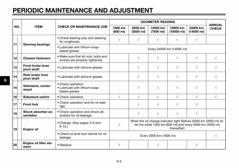
PERIODIC MAINTENANCE AND ADJUSTMENT
6-5
6
11 * Steering bearings
• Check bearing play and steering for roughness. √ √ √ √ √
• Lubricate with lithium-soap-based grease. Every 24000 km (14000 mi)
12 * Chassis fasteners• Make sure that all nuts, bolts and
screws are properly tightened. √ √ √ √ √
13Front brake lever pivot shaft
• Lubricate with silicone grease. √ √ √ √ √
14Rear brake lever pivot shaft
• Lubricate with silicone grease. √ √ √ √ √
15Sidestand, center-stand
• Check operation.• Lubricate with lithium-soap-
based grease.√ √ √ √ √
16 * Sidestand switch • Check operation. √ √ √ √ √ √
17 * Front fork• Check operation and for oil leak-
age. √ √ √ √
18 * Shock absorber as-semblies
• Check operation and shock ab-sorbers for oil leakage. √ √ √ √
19 Engine oil
• Change. (See pages 3-8 and 6-12.) √
When the oil change indicator light flashes (5000 km (3000 mi) af-ter the initial 1000 km [600 mi] and every 6000 km (3500 mi)
thereafter)
• Check oil level and vehicle for oil leakage. Every 3000 km (1800 mi) √
20Engine oil filter ele-ment
• Replace. √ √ √
NO. ITEM CHECK OR MAINTENANCE JOB
ODOMETER READINGANNUAL CHECK1000 km
(600 mi)6000 km (3500 mi)
12000 km (7000 mi)
18000 km (10500 mi)
24000 km (14000 mi)
U2DME1E0.book Page 5 Wednesday, October 23, 2013 1:37 PM
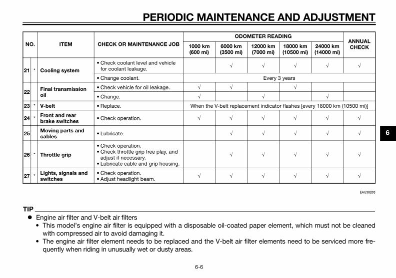
PERIODIC MAINTENANCE AND ADJUSTMENT
6-6
6
EAU38263
TIP
Engine air filter and V-belt air filters• This model’s engine air filter is equipped with a disposable oil-coated paper element, which must not be cleaned
with compressed air to avoid damaging it.• The engine air filter element needs to be replaced and the V-belt air filter elements need to be serviced more fre-
quently when riding in unusually wet or dusty areas.
21 * Cooling system
• Check coolant level and vehicle for coolant leakage. √ √ √ √ √
• Change coolant. Every 3 years
22Final transmission oil
• Check vehicle for oil leakage. √ √ √
• Change. √ √ √
23 * V-belt • Replace. When the V-belt replacement indicator flashes [every 18000 km (10500 mi)]
24 * Front and rear brake switches
• Check operation. √ √ √ √ √ √
25Moving parts and cables
• Lubricate. √ √ √ √ √
26 * Throttle grip
• Check operation.• Check throttle grip free play, and
adjust if necessary.• Lubricate cable and grip housing.
√ √ √ √ √
27 * Lights, signals and switches
• Check operation.• Adjust headlight beam. √ √ √ √ √ √
NO. ITEM CHECK OR MAINTENANCE JOB
ODOMETER READINGANNUAL CHECK1000 km
(600 mi)6000 km (3500 mi)
12000 km (7000 mi)
18000 km (10500 mi)
24000 km (14000 mi)
U2DME1E0.book Page 6 Wednesday, October 23, 2013 1:37 PM
PERIODIC MAINTENANCE AND ADJUSTMENT
6-7
6
Hydraulic brake service• After disassembling the brake master cylinders and calipers, always change the fluid. Regularly check the brake fluid
levels and fill the reservoirs as required.• Every two years replace the internal components of the brake master cylinders and calipers, and change the brake
fluid.• Replace the brake hoses every four years and if cracked or damaged.
U2DME1E0.book Page 7 Wednesday, October 23, 2013 1:37 PM

PERIODIC MAINTENANCE AND ADJUSTMENT
6-8
6
EAU18772
Removing and installing pan-elsThe panels shown need to be removedto perform some of the maintenancejobs described in this chapter. Refer tothis section each time a panel needs tobe removed and installed.
EAUM3340
Panel A
To remove the panel1. Open the front storage compart-
ment A. (See page 3-20.)2. Remove the screw, and then pull
the panel off.
To install the panelPlace the panel in the original position,and then install the screw.
Panel B
To remove the panel1. Open the front storage compart-
ment B. (See page 3-20.)2. Remove the screw, and then pull
the panel off.
1. Panel A2. Panel B
ZAUM1022
12
1. Panel CZAUM1021
1
1. Panel A2. Screw
ZAUM1046
1
2
U2DME1E0.book Page 8 Wednesday, October 23, 2013 1:37 PM
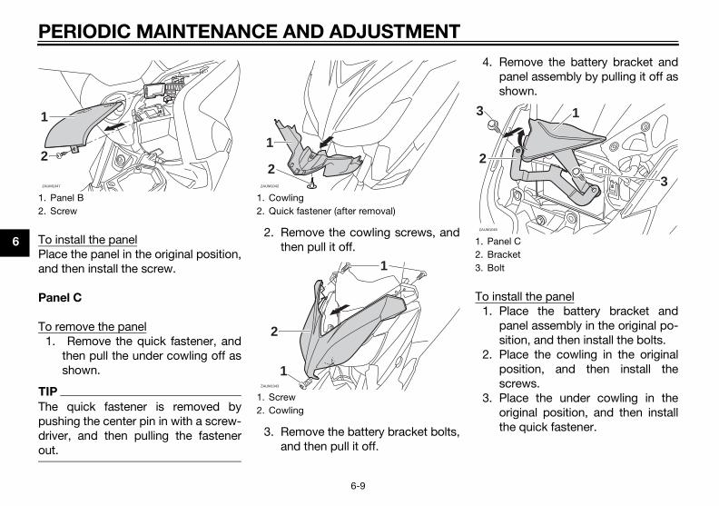
PERIODIC MAINTENANCE AND ADJUSTMENT
6-9
6 To install the panelPlace the panel in the original position,and then install the screw.
Panel C
To remove the panel1. Remove the quick fastener, and
then pull the under cowling off asshown.
TIP
The quick fastener is removed bypushing the center pin in with a screw-driver, and then pulling the fastenerout.
2. Remove the cowling screws, andthen pull it off.
3. Remove the battery bracket bolts,and then pull it off.
4. Remove the battery bracket andpanel assembly by pulling it off asshown.
To install the panel1. Place the battery bracket and
panel assembly in the original po-sition, and then install the bolts.
2. Place the cowling in the originalposition, and then install thescrews.
3. Place the under cowling in theoriginal position, and then installthe quick fastener.
1. Panel B2. Screw
ZAUM1047
1
2
1. Cowling2. Quick fastener (after removal)
1. Screw2. Cowling
ZAUM1042
1
2
ZAUM1043
2
1
1
1. Panel C2. Bracket3. Bolt
ZAUM1045
13
2
3
U2DME1E0.book Page 9 Wednesday, October 23, 2013 1:37 PM

PERIODIC MAINTENANCE AND ADJUSTMENT
6-10
6
TIP
To install the quick fastener, push thecenter pin out so that it will protrudefrom the fastener head, insert the fas-tener into the under cowling, and thenpush the protruding pin in until it isflush with the fastener head.
EAUM3360
Checking the spark plugThe spark plug is an important enginecomponent, which is easy to check.Since heat and deposits will cause anyspark plug to slowly erode, the sparkplug should be removed and checkedin accordance with the periodic main-tenance and lubrication chart. In addi-tion, the condition of the spark plugcan reveal the condition of the engine.
To remove the spark plug
1. Place the vehicle on the center-stand
2. Open the seat. (See page 3-19.)3. Remove the rear storage com-
partment by removing the bolts.
4. Remove the spark plug cap.
5. Remove the spark plug as shown,with the spark plug wrench includ-ed in the owner’s tool kit.
1. Storage compartment2. Bolt3. Rubber cap
1. Spark plug cap
ZAUM1040
2 3
1
ZAUM1117
1
U2DME1E0.book Page 10 Wednesday, October 23, 2013 1:37 PM

PERIODIC MAINTENANCE AND ADJUSTMENT
6-11
6
To check the spark plug
1. Check that the porcelain insulatoraround the center electrode of thespark plug is a medium-to-lighttan (the ideal color when the vehi-cle is ridden normally).
TIP
If the spark plug shows a distinctly dif-ferent color, the engine could be oper-ating improperly. Do not attempt todiagnose such problems yourself. In-stead, have a Yamaha dealer checkthe vehicle.
2. Check the spark plug for electrodeerosion and excessive carbon orother deposits, and replace it ifnecessary.
3. Measure the spark plug gap with awire thickness gauge and, if nec-essary, adjust the gap to specifi-cation.
To install the spark plug
1. Clean the surface of the sparkplug gasket and its mating sur-face, and then wipe off any grimefrom the spark plug threads.
2. Install the spark plug with thespark plug wrench, and then tight-en it to the specified torque.
TIP
If a torque wrench is not availablewhen installing a spark plug, a goodestimate of the correct torque is 1/4–1/2 turn past finger tight. However, thespark plug should be tightened to thespecified torque as soon as possible.
3. Install the spark plug cap.4. Place the rear storage compart-
ment in the original position andinstall the bolts.
5. Close the seat.
1. Spark plug wrenchZAUM1118
1 Specified spark plug:NGK/CPR9EA-9
1. Spark plug gap
Spark plug gap:0.8–0.9 mm (0.031–0.035 in)
1
Tightening torque:Spark plug:
12.5 Nm (1.25 m·kgf, 9.04 ft·lbf)
U2DME1E0.book Page 11 Wednesday, October 23, 2013 1:37 PM

PERIODIC MAINTENANCE AND ADJUSTMENT
6-12
6
EAUM3331
Engine oilThe engine oil level should be checkedbefore each ride. In addition, the oilmust be changed at the intervals spec-ified in the periodic maintenance andlubrication chart and when the serviceindicator light comes on.
To check the engine oil level
1. Place the scooter on the center-stand. A slight tilt to the side canresult in a false reading.
2. Start the engine, warm it up forseveral minutes, and then turn itoff.
3. Wait a few minutes until the oil set-tles, remove the oil filler cap, wipethe dipstick clean, insert it backinto the oil filler hole (withoutscrewing it in), and then remove itagain to check the oil level.
TIP
The engine oil should be between theminimum and maximum level marks.
4. If the engine oil is below the mini-mum level mark, add sufficient oilof the recommended type to raiseit to the correct level.
5. Insert the dipstick into the oil fillerhole, and then tighten the oil fillercap.
To change the engine oil (with or
without oil filter element replace-
ment)
1. Start the engine, warm it up forseveral minutes, and then turn itoff.
2. Place an oil pan under the engineto collect the used oil.
3. Remove the engine oil filler capand the engine oil drain bolt todrain the oil from the crankcase.
4. Check the drain bolt washer fordamage and replace it if neces-sary.
1. Engine oil filler cap2. Maximum level mark3. Minimum level mark
132
1
ZAUM0685
1. Engine oil drain bolt
1. Engine oil drain bolt2. Washer
ZAUM1119 1
12
ZAUM0129
U2DME1E0.book Page 12 Wednesday, October 23, 2013 1:37 PM
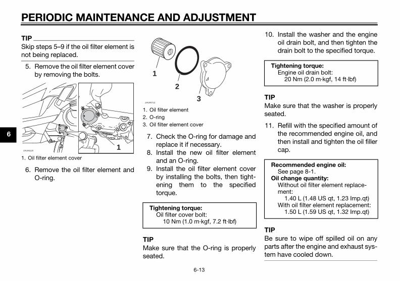
PERIODIC MAINTENANCE AND ADJUSTMENT
6-13
6
TIP
Skip steps 5–9 if the oil filter element isnot being replaced.
5. Remove the oil filter element coverby removing the bolts.
6. Remove the oil filter element andO-ring.
7. Check the O-ring for damage andreplace it if necessary.
8. Install the new oil filter elementand an O-ring.
9. Install the oil filter element coverby installing the bolts, then tight-ening them to the specifiedtorque.
TIP
Make sure that the O-ring is properlyseated.
10. Install the washer and the engineoil drain bolt, and then tighten thedrain bolt to the specified torque.
TIP
Make sure that the washer is properlyseated.
11. Refill with the specified amount ofthe recommended engine oil, andthen install and tighten the oil fillercap.
TIP
Be sure to wipe off spilled oil on anyparts after the engine and exhaust sys-tem have cooled down.
1. Oil filter element cover
ZAUM11201
1. Oil filter element2. O-ring3. Oil filter element cover
Tightening torque:Oil filter cover bolt:
10 Nm (1.0 m·kgf, 7.2 ft·lbf)
1
2
3ZAUM0712
Tightening torque:Engine oil drain bolt:
20 Nm (2.0 m·kgf, 14 ft·lbf)
Recommended engine oil:See page 8-1.
Oil change quantity:Without oil filter element replace-ment:
1.40 L (1.48 US qt, 1.23 Imp.qt)With oil filter element replacement:
1.50 L (1.59 US qt, 1.32 Imp.qt)
U2DME1E0.book Page 13 Wednesday, October 23, 2013 1:37 PM

PERIODIC MAINTENANCE AND ADJUSTMENT
6-14
6
NOTICEECA11671
Do not use oils with a diesel
specification of “CD” or oils of a
higher quality than specified. In
addition, do not use oils labeled
“ENERGY CONSERVING II” or
higher.
Be sure no foreign material en-
ters the crankcase.
12. Start the engine, and then let it idlefor several minutes while checkingit for oil leakage. If oil is leaking,immediately turn the engine offand check for the cause.
13. Turn the engine off, and thencheck the oil level and correct it ifnecessary.
14. Reset the oil change indicator.(See page 3-8.)
EAU20067
Final transmission oilThe final transmission case must bechecked for oil leakage before eachride. If any leakage is found, have aYamaha dealer check and repair thescooter. In addition, the final transmis-sion oil must be changed as follows atthe intervals specified in the periodicmaintenance and lubrication chart.
1. Start the engine, warm up the finaltransmission oil by riding thescooter for several minutes, andthen stop the engine.
2. Place the scooter on the center-stand.
3. Place an oil pan under the finaltransmission case to collect theused oil.
4. Remove the final transmission oilfiller cap and its O-ring from the fi-nal transmission case.
5. Remove the final transmission oildrain bolt and its gasket to drainthe oil from the final transmissioncase.
1. Final transmission oil filler cap2. O-ring
1. Final transmission oil drain bolt
ZAUM1123
ZAUM0703
1
U2DME1E0.book Page 14 Wednesday, October 23, 2013 1:37 PM
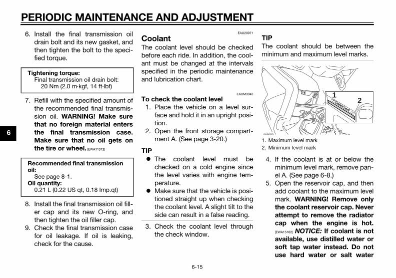
PERIODIC MAINTENANCE AND ADJUSTMENT
6-15
6
6. Install the final transmission oildrain bolt and its new gasket, andthen tighten the bolt to the speci-fied torque.
7. Refill with the specified amount ofthe recommended final transmis-sion oil. WARNING! Make sure
that no foreign material enters
the final transmission case.
Make sure that no oil gets on
the tire or wheel. [EWA11312]
8. Install the final transmission oil fill-er cap and its new O-ring, andthen tighten the oil filler cap.
9. Check the final transmission casefor oil leakage. If oil is leaking,check for the cause.
EAU20071
CoolantThe coolant level should be checkedbefore each ride. In addition, the cool-ant must be changed at the intervalsspecified in the periodic maintenanceand lubrication chart.
EAUM3043
To check the coolant level
1. Place the vehicle on a level sur-face and hold it in an upright posi-tion.
2. Open the front storage compart-ment A. (See page 3-20.)
TIP
The coolant level must bechecked on a cold engine sincethe level varies with engine tem-perature.
Make sure that the vehicle is posi-tioned straight up when checkingthe coolant level. A slight tilt to theside can result in a false reading.
3. Check the coolant level throughthe check window.
TIP
The coolant should be between theminimum and maximum level marks.
4. If the coolant is at or below theminimum level mark, remove pan-el A. (See page 6-8.)
5. Open the reservoir cap, and thenadd coolant to the maximum levelmark. WARNING! Remove only
the coolant reservoir cap. Never
attempt to remove the radiator
cap when the engine is hot.
[EWA15162] NOTICE: If coolant is not
available, use distilled water or
soft tap water instead. Do not
use hard water or salt water
Tightening torque:Final transmission oil drain bolt:
20 Nm (2.0 m·kgf, 14 ft·lbf)
Recommended final transmission oil:
See page 8-1.Oil quantity:
0.21 L (0.22 US qt, 0.18 Imp.qt)
1. Maximum level mark2. Minimum level mark
ZAUM1029
21
Coolant Level
Coolant Level
HighHigh
LowLow
U2DME1E0.book Page 15 Wednesday, October 23, 2013 1:37 PM

PERIODIC MAINTENANCE AND ADJUSTMENT
6-16
6
since it is harmful to the engine.
If water has been used instead
of coolant, replace it with cool-
ant as soon as possible, other-
wise the cooling system will not
be protected against frost and
corrosion. If water has been
added to the coolant, have a
Yamaha dealer check the anti-
freeze content of the coolant as
soon as possible, otherwise the
effectiveness of the coolant will
be reduced. [ECA10473]
6. Close the reservoir cap, and theninstall the panel.
7. Close the front storage compart-ment.
EAU33032
Changing the coolant
The coolant must be changed at the in-tervals specified in the periodic main-tenance and lubrication chart. Have aYamaha dealer change the coolant.WARNING! Never attempt to remove
the radiator cap when the engine is
hot. [EWA10382]
EAUM3370
Air filter and V-belt case air fil-ter elements and check hosesThe air filter element should be re-placed and the V-belt case air filter el-ement should be cleaned at theintervals specified in the periodic main-tenance and lubrication chart. Servicethe air filter elements more frequently ifyou are riding in unusually wet or dustyareas.
Replacing the air filter element
1. Place the scooter on the center-stand.
2. Remove the air filter case cover byremoving the screws.
1. Coolant reservoir cap
Coolant reservoir capacity:0.32 L (0.34 US qt, 0.28 Imp.qt)
ZAUM1030
1
1. Air filter case cover2. Screw3. Air filter element
ZAUM1124
1
2
2
3
U2DME1E0.book Page 16 Wednesday, October 23, 2013 1:37 PM

PERIODIC MAINTENANCE AND ADJUSTMENT
6-17
6
3. Pull the air filter element out.4. Insert a new air filter element into
the air filter case.5. Install the air filter case cover by
installing the screws.
To clean the air filter check hoses
1. Check the hoses at the bottom ofair filter case for accumulated dirtor water.
Left
2. If dirt or water is visible, removethe hose, clean it, and then installit.
Cleaning the V-belt case air filter el-
ement
1. Remove the V-belt case air filtercovers by removing the screws.
2. Remove the air filter element, andthen blow out the dirt with com-pressed air as shown.
3. Check the air filter element fordamage and replace it if neces-sary.
4. Install the air filter element with thecolored side facing outward.
5. Install the V-belt case air filter cov-ers by installing the screws.NOTICE: Make sure that each
filter element is properly seated
in its case. The engine should
never be operated without the
filter elements installed, other-
wise the piston(s) and/or cylin-
der(s) may become excessively
worn. [ECA10532]
1. Air filter check hoseZAUM1126
1
1. V-belt case air filter cover2. Screw
ZAUM1125
1. V-belt case air filter element
1ZAUM0706
U2DME1E0.book Page 17 Wednesday, October 23, 2013 1:37 PM

PERIODIC MAINTENANCE AND ADJUSTMENT
6-18
6
EAU21385
Checking the throttle grip free play
The throttle grip free play should mea-sure 3.0–5.0 mm (0.12–0.20 in) at theinner edge of the throttle grip. Periodi-cally check the throttle grip free playand, if necessary, have a Yamaha deal-er adjust it.
EAU21402
Valve clearanceThe valve clearance changes with use,resulting in improper air-fuel mixtureand/or engine noise. To prevent thisfrom occurring, the valve clearancemust be adjusted by a Yamaha dealerat the intervals specified in the periodicmaintenance and lubrication chart.
EAU21877
TiresTires are the only contact between thevehicle and the road. Safety in all con-ditions of riding depends on a relativelysmall area of road contact. Therefore, itis essential to maintain the tires in goodcondition at all times and replace themat the appropriate time with the speci-fied tires.
Tire air pressure
The tire air pressure should bechecked and, if necessary, adjustedbefore each ride.
1. Throttle grip free play
ZAUM0053
U2DME1E0.book Page 18 Wednesday, October 23, 2013 1:37 PM

PERIODIC MAINTENANCE AND ADJUSTMENT
6-19
6
WARNING
EWA10504
Operation of this vehicle with im-
proper tire pressure may cause se-
vere injury or death from loss of
control.
The tire air pressure must be
checked and adjusted on cold
tires (i.e., when the temperature
of the tires equals the ambient
temperature).
The tire air pressure must be
adjusted in accordance with the
riding speed and with the total
weight of rider, passenger, car-
go, and accessories approved
for this model.
WARNING
EWA10512
Never overload your vehicle. Opera-
tion of an overloaded vehicle could
cause an accident.
Tire inspection
The tires must be checked before eachride. If the center tread depth reachesthe specified limit, if the tire has a nailor glass fragments in it, or if the side-wall is cracked, have a Yamaha dealerreplace the tire immediately.
TIP
The tire tread depth limits may differfrom country to country. Always com-ply with the local regulations.
Tire air pressure (measured on cold tires):
0–90 kg (0–198 lb):Front:
190 kPa (1.90 kgf/cm², 28 psi)Rear:
220 kPa (2.20 kgf/cm², 32 psi)YP125R 90–185 kg (198–408 lb)YP125RA 90–181 kg (198–399 lb):
Front:210 kPa (2.10 kgf/cm², 30 psi)
Rear:250 kPa (2.50 kgf/cm², 36 psi)
Maximum load*:YP125R 185 kg (408 lb)YP125RA 181 kg (399 lb)
* Total weight of rider, passenger, car-go and accessories
1. Tire sidewall2. Tire tread depth
Minimum tire tread depth (front and rear):
1.6 mm (0.06 in)
1
2
U2DME1E0.book Page 19 Wednesday, October 23, 2013 1:37 PM

PERIODIC MAINTENANCE AND ADJUSTMENT
6-20
6
Tire information
This model is equipped with tubelesstires.Tires age, even if they have not beenused or have only been used occasion-ally. Cracking of the tread and sidewallrubber, sometimes accompanied bycarcass deformation, is an evidence ofageing. Old and aged tires shall bechecked by tire specialists to ascertaintheir suitability for further use.After extensive tests, only the tires list-ed below have been approved for thismodel by Yamaha Motor Co., Ltd.
WARNING
EWA10472
Have a Yamaha dealer replace
excessively worn tires. Besides
being illegal, operating the vehi-
cle with excessively worn tires
decreases riding stability and
can lead to loss of control.
The replacement of all wheel
and brake-related parts, includ-
ing the tires, should be left to a
Yamaha dealer, who has the
necessary professional knowl-
edge and experience to do so.
Ride at moderate speeds after
changing a tire since the tire
surface must first be “broken
in” for it to develop its optimal
characteristics.
EAU21963
Cast wheelsTo maximize the performance, durabil-ity, and safe operation of your vehicle,note the following points regarding thespecified wheels. The wheel rims should be
checked for cracks, bends, warp-age or other damage before eachride. If any damage is found, havea Yamaha dealer replace thewheel. Do not attempt even thesmallest repair to the wheel. A de-formed or cracked wheel must bereplaced.
The wheel should be balancedwhenever either the tire or wheelhas been changed or replaced. Anunbalanced wheel can result inpoor performance, adverse han-dling characteristics, and a short-ened tire life.
Front tire:Size:
120/70-15 M/C 56P(METZELER)-56S(MICHELIN)
Manufacturer/model:METZELER / FEELFREEMICHELIN / CITYGRIP
Rear tire:Size:
140/70-14 M/C 68P(METZELER)-68S(MICHELIN)
Manufacturer/model:METZELER / FEELFREEMICHELIN / CITYGRIP
U2DME1E0.book Page 20 Wednesday, October 23, 2013 1:37 PM

PERIODIC MAINTENANCE AND ADJUSTMENT
6-21
6
EAU50861
Checking the front and rear brake lever free play
Front
Rear
There should be no free play at thebrake lever ends. If there is free play,have a Yamaha dealer inspect thebrake system.
WARNING
EWA14212
A soft or spongy feeling in the brake
lever can indicate the presence of
air in the hydraulic system. If there is
air in the hydraulic system, have a
Yamaha dealer bleed the system be-
fore operating the vehicle. Air in the
hydraulic system will diminish the
braking performance, which may re-
sult in loss of control and an acci-
dent.
EAU22393
Checking the front and rear brake padsThe front and rear brake pads must bechecked for wear at the intervals spec-ified in the periodic maintenance andlubrication chart.
EAU22432
Front brake pads
Each front brake pad is provided withwear indicator grooves, which allowyou to check the brake pad wear with-out having to disassemble the brake.To check the brake pad wear, checkthe wear indicator grooves. If a brakepad has worn to the point that the wear
1. No brake lever free play
1. No brake lever free play
ZAUM1049
ZAUM1050
1. Wear indicator groove
11
ZAUM1127
U2DME1E0.book Page 21 Wednesday, October 23, 2013 1:37 PM

PERIODIC MAINTENANCE AND ADJUSTMENT
6-22
6
indicator grooves have almost disap-peared, have a Yamaha dealer replacethe brake pads as a set.
EAUS1992
Rear brake pads
The rear brake is provided with a checkplug, which, if it is removed, allows youto check the brake pad wear withoutdisassembling the brake.
YP125R
If the lining thickness is less than 3.5mm (0.14 in), have a Yamaha dealer re-place the brake pads as a set.
YP125RA
To check the brake pad wear, checkthe position of the wear indicator whileapplying the brake. If a brake pad hasworn to the point that the wear indica-tor almost touches the brake disc,have a Yamaha dealer replace thebrake pads as a set.
EAU40262
Checking the brake fluid levelBefore riding, check that the brake fluidis above the minimum level mark.Check the brake fluid level with the topof the reservoir level. Replenish thebrake fluid if necessary.
Front brake
1. Lining thicknessZAUM1133
1. Brake pad wear indicator groove 1. Minimum level mark
1
ZAUM1057
U2DME1E0.book Page 22 Wednesday, October 23, 2013 1:37 PM

PERIODIC MAINTENANCE AND ADJUSTMENT
6-23
6
Rear brake
WARNING
EWA16011
Improper maintenance can result in
loss of braking ability. Observe
these precautions:
Insufficient brake fluid may al-
low air to enter the brake sys-
tem, reducing braking
performance.
Clean the filler cap before re-
moving. Use only DOT 4 brake
fluid from a sealed container.
Use only the specified brake flu-
id; otherwise, the rubber seals
may deteriorate, causing leak-
age.
Refill with the same type of
brake fluid. Adding a brake fluid
other than DOT 4 may result in a
harmful chemical reaction.
Be careful that water or dust
does not enter the brake fluid
reservoir when refilling. Water
will significantly lower the boil-
ing point of the fluid and may re-
sult in vapor lock, and dirt may
clog the ABS hydraulic unit
valves.
NOTICEECA17641
Brake fluid may damage painted
surfaces or plastic parts. Always
clean up spilled fluid immediately.
As the brake pads wear, it is normal forthe brake fluid level to gradually godown. A low brake fluid level may indi-cate worn brake pads and/or brakesystem leakage; therefore, be sure tocheck the brake pads for wear and thebrake system for leakage. If the brake
fluid level goes down suddenly, have aYamaha dealer check the cause beforefurther riding.
1. Minimum level mark
Specified brake fluid:DOT 4
ZAUM1032
1
U2DME1E0.book Page 23 Wednesday, October 23, 2013 1:37 PM
PERIODIC MAINTENANCE AND ADJUSTMENT
6-24
6
EAU22733
Changing the brake fluidHave a Yamaha dealer change thebrake fluid at the intervals specified inthe periodic maintenance and lubrica-tion chart. In addition, have the oil sealsof the master cylinders and calipers aswell as the brake hoses replaced at theintervals listed below or whenever theyare damaged or leaking. Oil seals: Replace every two
years. Brake hoses: Replace every four
years.
EAU23098
Checking and lubricating the cablesThe operation of all control cables andthe condition of the cables should bechecked before each ride, and the ca-bles and cable ends should be lubri-cated if necessary. If a cable isdamaged or does not move smoothly,have a Yamaha dealer check or re-place it. WARNING! Damage to the
outer housing of cables may result
in internal rusting and cause inter-
ference with cable movement. Re-
place damaged cables as soon as
possible to prevent unsafe condi-
tions. [EWA10712]
EAU23115
Checking and lubricating the throttle grip and cableThe operation of the throttle gripshould be checked before each ride. Inaddition, the cable should be lubricat-ed by a Yamaha dealer at the intervalsspecified in the periodic maintenancechart.The throttle cable is equipped with arubber cover. Make sure that the coveris securely installed. Even though thecover is installed correctly, it does notcompletely protect the cable from wa-ter entry. Therefore, use care not topour water directly onto the cover orcable when washing the vehicle. If thecable or cover becomes dirty, wipeclean with a moist cloth.Recommended lubricant:
Yamaha cable lubricant or other suitable cable lubricant
U2DME1E0.book Page 24 Wednesday, October 23, 2013 1:37 PM

PERIODIC MAINTENANCE AND ADJUSTMENT
6-25
6
EAU23173
Lubricating the front and rear brake levers
Front brake lever
Rear brake lever
The pivoting points of the front and rearbrake levers must be lubricated at theintervals specified in the periodic main-tenance and lubrication chart.
EAU23215
Checking and lubricating the centerstand and sidestand
Recommended lubricant:Silicone grease
1. Sidestand
1. Centerstand
U2DME1E0.book Page 25 Wednesday, October 23, 2013 1:37 PM

PERIODIC MAINTENANCE AND ADJUSTMENT
6-26
6
The operation of the centerstand andsidestand should be checked beforeeach ride, and the pivots and metal-to-metal contact surfaces should be lubri-cated if necessary.
WARNING
EWA10742
If the centerstand or sidestand does
not move up and down smoothly,
have a Yamaha dealer check or re-
pair it. Otherwise, the centerstand or
sidestand could contact the ground
and distract the operator, resulting
in a possible loss of control.
EAU23273
Checking the front forkThe condition and operation of thefront fork must be checked as followsat the intervals specified in the periodicmaintenance and lubrication chart.
To check the condition
Check the inner tubes for scratches,damage and excessive oil leakage.
To check the operation
1. Place the vehicle on a level sur-face and hold it in an upright posi-tion. WARNING! To avoid injury,
securely support the vehicle so
there is no danger of it falling
over. [EWA10752]
2. While applying the front brake,push down hard on the handle-bars several times to check if thefront fork compresses and re-bounds smoothly.
NOTICEECA10591
If any damage is found or the front
fork does not operate smoothly,
have a Yamaha dealer check or re-
pair it.Recommended lubricant:Lithium-soap-based grease
U2DME1E0.book Page 26 Wednesday, October 23, 2013 1:37 PM

PERIODIC MAINTENANCE AND ADJUSTMENT
6-27
6
EAU45512
Checking the steeringWorn or loose steering bearings maycause danger. Therefore, the operationof the steering must be checked as fol-lows at the intervals specified in theperiodic maintenance and lubricationchart.
1. Place the vehicle on the center-stand. WARNING! To avoid inju-
ry, securely support the vehicle
so there is no danger of it falling
over. [EWA10752]
2. Hold the lower ends of the frontfork legs and try to move them for-ward and backward. If any freeplay can be felt, have a Yamahadealer check or repair the steer-ing.
EAU23292
Checking the wheel bearings
The front and rear wheel bearings mustbe checked at the intervals specified inthe periodic maintenance and lubrica-tion chart. If there is play in the wheelhub or if the wheel does not turnsmoothly, have a Yamaha dealercheck the wheel bearings.
EAU46344
Battery
The battery is located behind panel C.(See page 6-8.)This model is equipped with a VRLA(Valve Regulated Lead Acid) battery.There is no need to check the electro-lyte or to add distilled water. However,the battery lead connections need tobe checked and, if necessary, securelytightened.
WARNING
EWA10761
Electrolyte is poisonous and
dangerous since it contains sul-
furic acid, which causes severeZAUM1128
1. Positive battery lead (red)2. Negative battery lead (black)3. Battery
ZAUM1035
2
13
U2DME1E0.book Page 27 Wednesday, October 23, 2013 1:37 PM
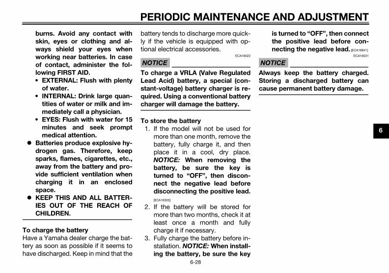
PERIODIC MAINTENANCE AND ADJUSTMENT
6-28
6
burns. Avoid any contact with
skin, eyes or clothing and al-
ways shield your eyes when
working near batteries. In case
of contact, administer the fol-
lowing FIRST AID.
• EXTERNAL: Flush with plenty
of water.
• INTERNAL: Drink large quan-
tities of water or milk and im-
mediately call a physician.
• EYES: Flush with water for 15
minutes and seek prompt
medical attention.
Batteries produce explosive hy-
drogen gas. Therefore, keep
sparks, flames, cigarettes, etc.,
away from the battery and pro-
vide sufficient ventilation when
charging it in an enclosed
space.
KEEP THIS AND ALL BATTER-
IES OUT OF THE REACH OF
CHILDREN.
To charge the battery
Have a Yamaha dealer charge the bat-tery as soon as possible if it seems tohave discharged. Keep in mind that the
battery tends to discharge more quick-ly if the vehicle is equipped with op-tional electrical accessories.
NOTICEECA16522
To charge a VRLA (Valve Regulated
Lead Acid) battery, a special (con-
stant-voltage) battery charger is re-
quired. Using a conventional battery
charger will damage the battery.
To store the battery
1. If the model will not be used formore than one month, remove thebattery, fully charge it, and thenplace it in a cool, dry place.NOTICE: When removing the
battery, be sure the key is
turned to “OFF”, then discon-
nect the negative lead before
disconnecting the positive lead.
[ECA16303]
2. If the battery will be stored formore than two months, check it atleast once a month and fullycharge it if necessary.
3. Fully charge the battery before in-stallation. NOTICE: When install-
ing the battery, be sure the key
is turned to “OFF”, then connect
the positive lead before con-
necting the negative lead. [ECA16841]
NOTICEECA16531
Always keep the battery charged.
Storing a discharged battery can
cause permanent battery damage.
U2DME1E0.book Page 28 Wednesday, October 23, 2013 1:37 PM

PERIODIC MAINTENANCE AND ADJUSTMENT
6-29
6
EAUM3092
Replacing the fusesThe fuse box, which contains the fusesfor the individual circuits, is located be-hind panel B. (See page 6-8.)
TIP
The main fuse, which is in a differentand hard-to-reach location, must bereplaced by a Yamaha dealer.
If a fuse for the individual circuits isblown, replace it as follows.
1. Turn the key to “OFF” and turn offthe electrical circuit in question.
2. Remove the blown fuse, and theninstall a new fuse of the specifiedamperage. WARNING! Do not
use a fuse of a higher amperage
rating than recommended to
avoid causing extensive dam-
age to the electrical system and
possibly a fire. [EWA15132]
TIP
Fuse tongs are included in the owner’stool kit. Use the tongs to remove andinstall a fuse.
YP125R
1. Main fuse2. Spare main fuse
ZAUM1058
1 12
1. Fuse boxZAUM1036
1
1. Radiator fan fuse2. ECU fuse3. Backup fuse4. Signaling system fuse5. Headlight fuse6. Ignition fuse7. Spare fuse8. Hazard fuse
ZAUM1037
7
1 2 3 4 5 6
2010
10
20 101010107.5
7.5
U2DME1E0.book Page 29 Wednesday, October 23, 2013 1:37 PM

PERIODIC MAINTENANCE AND ADJUSTMENT
6-30
6
YP125RA
3. Turn the key to “ON” and turn onthe electrical circuit in question tocheck if the device operates.
4. If the fuse immediately blowsagain, have a Yamaha dealercheck the electrical system.
EAU34242
Replacing a headlight bulbThis model is equipped with halogenbulb headlights. If a headlight bulbburns out, have a Yamaha dealer re-place it and, if necessary, adjust theheadlight beam.
1. Radiator fan fuse2. ECU fuse3. Backup fuse4. Signaling system fuse5. Headlight fuse6. Ignition fuse7. Spare fuse8. Hazard fuse9. ABS control unit fuse10.ABS motor fuse11.ABS solenoid fuse
ZAUM1129
10 1010
20 3030
77
11
1 2 3 4 5 6
2010
20 101010107.5
7.5
910
Specified fuses:Main fuse:
30.0 AIgnition fuse:
10.0 ASignaling system fuse:
10.0 AHeadlight fuse:
20.0 ATurn signal light and hazard fuse:
10.0 ARadiator fan fuse:
7.5 AABS control unit fuse:
YP125RA 10.0 AABS motor fuse:
YP125RA 30.0 AABS solenoid fuse:
YP125RA 20.0 ABackup fuse:
10.0 A
U2DME1E0.book Page 30 Wednesday, October 23, 2013 1:37 PM

PERIODIC MAINTENANCE AND ADJUSTMENT
6-31
6
EAU24182
Tail/brake lightThis model is equipped with an LED-type tail/brake light.If the tail/brake light does not come on,have a Yamaha dealer check it.
EAU39881
Front turn signal lightIf a front turn signal light does notcome on, have a Yamaha dealer checkits electrical circuit or replace the bulb.
EAUM3062
Replacing a rear turn signal light bulb
1. Place the scooter on the center-stand.
2. Open the seat. (See page 3-19.)3. Remove the rear storage com-
partment by removing the bolts.4. Remove the socket (together with
the turn signal light bulb) by turn-ing it counterclockwise.
5. Remove the burnt-out bulb bypushing it in and turning it coun-terclockwise.
1. Storage compartment2. Bolt3. Rubber cap
ZAUM1040
2 3
1
U2DME1E0.book Page 31 Wednesday, October 23, 2013 1:37 PM

PERIODIC MAINTENANCE AND ADJUSTMENT
6-32
6
6. Insert a new bulb into the socket,push it in, and then turn it clock-wise until it stops.
7. Install the socket (together withthe bulb) by turning it clockwise.
8. Place the rear storage compart-ment in the original position andinstall the bolts.
9. Close the seat.
EAUM2203
Replacing the license plate light bulb
1. Remove the socket (together withthe bulb) by pulling it out.
2. Remove the burnt-out bulb bypulling it out.
3. Insert a new bulb into the socket.4. Install the socket (together with
the bulb) by pushing it in.
1. Turn signal light bulb socket
1. Turn signal light bulb2. Turn signal light bulb socket
ZAUM1038
1
ZAUM1039
12
1. License plate light bulb socket
ZAUM0681
1
U2DME1E0.book Page 32 Wednesday, October 23, 2013 1:37 PM

PERIODIC MAINTENANCE AND ADJUSTMENT
6-33
6
EAU54501
Auxiliary lightThis model is equipped with LED-typeauxiliary lights.If an auxiliary light does not come on,have a Yamaha dealer check it.
EAU25882
TroubleshootingAlthough Yamaha scooters receive athorough inspection before shipmentfrom the factory, trouble may occurduring operation. Any problem in thefuel, compression, or ignition systems,for example, can cause poor startingand loss of power.The following troubleshooting chartsrepresent quick and easy proceduresfor checking these vital systems your-self. However, should your scooter re-quire any repair, take it to a Yamahadealer, whose skilled technicians havethe necessary tools, experience, andknow-how to service the scooter prop-erly.Use only genuine Yamaha replace-ment parts. Imitation parts may looklike Yamaha parts, but they are ofteninferior, have a shorter service life andcan lead to expensive repair bills.
WARNING
EWA15142
When checking the fuel system, do
not smoke, and make sure there are
no open flames or sparks in the ar-
ea, including pilot lights from water
heaters or furnaces. Gasoline or
gasoline vapors can ignite or ex-
plode, causing severe injury or prop-
erty damage.
U2DME1E0.book Page 33 Wednesday, October 23, 2013 1:37 PM
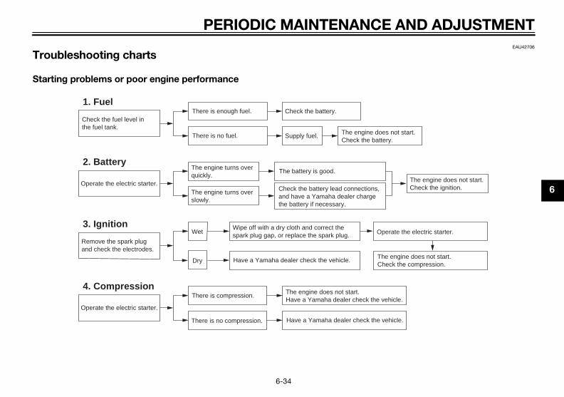
PERIODIC MAINTENANCE AND ADJUSTMENT
6-34
6
EAU42706
Troubleshooting charts
Starting problems or poor engine performance
Check the fuel level inthe fuel tank.
1. FuelThere is enough fuel.
There is no fuel.
Check the battery.
Supply fuel. The engine does not start. Check the battery.
Operate the electric starter.
4. CompressionThere is compression.
There is no compression.
The engine does not start. Have a Yamaha dealer check the vehicle.
Have a Yamaha dealer check the vehicle.
Remove the spark plugand check the electrodes.
3. Ignition Wipe off with a dry cloth and correct thespark plug gap, or replace the spark plug.
Have a Yamaha dealer check the vehicle. The engine does not start.Check the compression.
Operate the electric starter.
2. BatteryThe engine turns over quickly.
The engine turns over slowly.
The battery is good.
Dry
Wet Operate the electric starter.
Check the battery lead connections,and have a Yamaha dealer charge the battery if necessary.
The engine does not start.Check the ignition.
U2DME1E0.book Page 34 Wednesday, October 23, 2013 1:37 PM

PERIODIC MAINTENANCE AND ADJUSTMENT
6-35
6
Engine overheating
WARNING
EWAT1041
Do not remove the radiator cap when the engine and radiator are hot. Scalding hot fluid and steam may be
blown out under pressure, which could cause serious injury. Be sure to wait until the engine has cooled.
Place a thick rag, like a towel, over the radiator cap, and then slowly rotate the cap counterclockwise to the
detent to allow any residual pressure to escape. When the hissing sound has stopped, press down on the cap
while turning it counterclockwise, and then remove the cap.
TIP
If coolant is not available, tap water can be temporarily used instead, provided that it is changed to the recommended cool-ant as soon as possible.
Wait until the engine has cooled.
Check the coolant level in the reservoir and radiator.
The coolant level is OK.
The coolant level is low.Check the cooling systemfor leakage.
Have a Yamaha dealer checkand repair the cooling system.
Add coolant. (See TIP.)
Start the engine. If the engine overheats again, have a Yamaha dealer check and repair the cooling system.
There isleakage.
There is no leakage.
U2DME1E0.book Page 35 Wednesday, October 23, 2013 1:37 PM

SCOOTER CARE AND STORAGE
7-1
7
EAU37834
Matte color caution
NOTICEECA15193
Some models are equipped with
matte colored finished parts. Be
sure to consult a Yamaha dealer for
advice on what products to use be-
fore cleaning the vehicle. Using a
brush, harsh chemical products or
cleaning compounds when cleaning
these parts will scratch or damage
their surface. Wax also should not
be applied to any matte colored fin-
ished parts.
EAU26096
CareWhile the open design of a scooter re-veals the attractiveness of the technol-ogy, it also makes it more vulnerable.Rust and corrosion can develop even ifhigh-quality components are used. Arusty exhaust pipe may go unnoticedon a car, however, it detracts from theoverall appearance of a scooter. Fre-quent and proper care does not onlycomply with the terms of the warranty,but it will also keep your scooter look-ing good, extend its life and optimizeits performance.
Before cleaning
1. Cover the muffler outlet with aplastic bag after the engine hascooled down.
2. Make sure that all caps and cov-ers as well as all electrical cou-plers and connectors, includingthe spark plug cap, are tightly in-stalled.
3. Remove extremely stubborn dirt,like oil burnt onto the crankcase,with a degreasing agent and abrush, but never apply such prod-
ucts onto seals, gaskets andwheel axles. Always rinse the dirtand degreaser off with water.
Cleaning
NOTICEECA10784
Avoid using strong acidic wheel
cleaners, especially on spoked
wheels. If such products are
used on hard-to-remove dirt, do
not leave the cleaner on the af-
fected area any longer than in-
structed. Also, thoroughly rinse
the area off with water, immedi-
ately dry it, and then apply a cor-
rosion protection spray.
Improper cleaning can damage
plastic parts (such as cowlings,
panels, windshields, headlight
lenses, meter lenses, etc.) and
the mufflers. Use only a soft,
clean cloth or sponge with wa-
ter to clean plastic. However, if
the plastic parts cannot be thor-
oughly cleaned with water, di-
luted mild detergent with water
may be used. Be sure to rinse
U2DME1E0.book Page 1 Wednesday, October 23, 2013 1:37 PM

SCOOTER CARE AND STORAGE
7-2
7
off any detergent residue using
plenty of water, as it is harmful
to plastic parts.
Do not use any harsh chemical
products on plastic parts. Be
sure to avoid using cloths or
sponges which have been in
contact with strong or abrasive
cleaning products, solvent or
thinner, fuel (gasoline), rust re-
movers or inhibitors, brake fluid,
antifreeze or electrolyte.
Do not use high-pressure wash-
ers or steam-jet cleaners since
they cause water seepage and
deterioration in the following ar-
eas: seals (of wheel and swing-
arm bearings, fork and brakes),
electric components (couplers,
connectors, instruments,
switches and lights), breather
hoses and vents.
For scooters equipped with a
windshield: Do not use strong
cleaners or hard sponges as
they will cause dulling or
scratching. Some cleaning
compounds for plastic may
leave scratches on the wind-
shield. Test the product on a
small hidden part of the wind-
shield to make sure that it does
not leave any marks. If the wind-
shield is scratched, use a quality
plastic polishing compound af-
ter washing.
After normal useRemove dirt with warm water, a milddetergent, and a soft, clean sponge,and then rinse thoroughly with cleanwater. Use a toothbrush or bottlebrushfor hard-to-reach areas. Stubborn dirtand insects will come off more easily ifthe area is covered with a wet cloth fora few minutes before cleaning.
After riding in the rain, near the sea oron salt-sprayed roadsSince sea salt or salt sprayed on theroads during winter are extremely cor-rosive in combination with water, carryout the following steps after each ridein the rain, near the sea or on salt-sprayed roads.
TIP
Salt sprayed on roads in the wintermay remain well into spring.
1. Clean the scooter with cold waterand a mild detergent after the en-gine has cooled down. NOTICE:Do not use warm water since it
increases the corrosive action
of the salt. [ECA10792]
2. Apply a corrosion protection sprayon all metal, including chrome-and nickel-plated, surfaces to pre-vent corrosion.
Cleaning the windshieldAvoid using any alkaline or strong acidcleaner, gasoline, brake fluid, or anyother solvent. Clean the windshieldwith a cloth or sponge dampened witha mild detergent, and then wash it offthoroughly with water. For additionalcleaning, use Yamaha WindshieldCleaner or another high-quality wind-shield cleaner. Some cleaning com-pounds for plastics may leavescratches on the windshield. Beforeusing such cleaners, test an area of the
U2DME1E0.book Page 2 Wednesday, October 23, 2013 1:37 PM
SCOOTER CARE AND STORAGE
7-3
7
windshield which does not affect yourvisibility and which cannot be easilyrecognized.
After cleaning
1. Dry the scooter with a chamois oran absorbing cloth.
2. Use a chrome polish to shinechrome, aluminum and stainless-steel parts, including the exhaustsystem. (Even the thermally in-duced discoloring of stainless-steel exhaust systems can be re-moved through polishing.)
3. To prevent corrosion, it is recom-mended to apply a corrosion pro-tection spray on all metal,including chrome- and nickel-plat-ed, surfaces.
4. Use spray oil as a universal clean-er to remove any remaining dirt.
5. Touch up minor paint damagecaused by stones, etc.
6. Wax all painted surfaces.7. Let the scooter dry completely be-
fore storing or covering it.
WARNING
EWA10943
Contaminants on the brakes or tires
can cause loss of control.
Make sure that there is no oil or
wax on the brakes or tires. If
necessary, clean the brake
discs and brake linings with a
regular brake disc cleaner or
acetone, and wash the tires with
warm water and a mild deter-
gent.
Before operating the scooter
test its braking performance
and cornering behavior.
NOTICEECA10801
Apply spray oil and wax spar-
ingly and make sure to wipe off
any excess.
Never apply oil or wax to any
rubber and plastic parts, but
treat them with a suitable care
product.
Avoid using abrasive polishing
compounds as they will wear
away the paint.
TIP
Consult a Yamaha dealer for ad-vice on what products to use.
Washing, rainy weather or humidclimates can cause the headlightlens to fog. Turning the headlighton for a short period of time willhelp remove the moisture from thelens.
U2DME1E0.book Page 3 Wednesday, October 23, 2013 1:37 PM

SCOOTER CARE AND STORAGE
7-4
7
EAU36564
Storage
Short-term
Always store your scooter in a cool, dryplace and, if necessary, protect itagainst dust with a porous cover. Besure the engine and the exhaust sys-tem are cool before covering thescooter.
NOTICEECA10821
Storing the scooter in a poorly
ventilated room or covering it
with a tarp, while it is still wet,
will allow water and humidity to
seep in and cause rust.
To prevent corrosion, avoid
damp cellars, stables (because
of the presence of ammonia)
and areas where strong chemi-
cals are stored.
Long-term
Before storing your scooter for severalmonths:
1. Follow all the instructions in the“Care” section of this chapter.
2. Fill up the fuel tank and add fuelstabilizer (if available) to preventthe fuel tank from rusting and thefuel from deteriorating.
3. Perform the following steps toprotect the cylinder, piston rings,etc. from corrosion.a. Remove the spark plug cap
and spark plug.b. Pour a teaspoonful of engine
oil into the spark plug bore.c. Install the spark plug cap onto
the spark plug, and then placethe spark plug on the cylinderhead so that the electrodes aregrounded. (This will limit spark-ing during the next step.)
d. Turn the engine over severaltimes with the starter. (This willcoat the cylinder wall with oil.)
e. Remove the spark plug capfrom the spark plug, and theninstall the spark plug and thespark plug cap. WARNING! To
prevent damage or injury
from sparking, make sure to
ground the spark plug elec-
trodes while turning the en-
gine over. [EWA10952]
4. Lubricate all control cables andthe pivoting points of all levers andpedals as well as of the side-stand/centerstand.
5. Check and, if necessary, correctthe tire air pressure, and then liftthe scooter so that both of itswheels are off the ground. Alterna-tively, turn the wheels a little everymonth in order to prevent the tiresfrom becoming degraded in onespot.
6. Cover the muffler outlet with aplastic bag to prevent moisturefrom entering it.
7. Remove the battery and fullycharge it. Store it in a cool, dryplace and charge it once a month.Do not store the battery in an ex-cessively cold or warm place [lessthan 0 °C (30 °F) or more than 30°C (90 °F)]. For more informationon storing the battery, see page6-27.
TIP
Make any necessary repairs beforestoring the scooter.
U2DME1E0.book Page 4 Wednesday, October 23, 2013 1:37 PM

SPECIFICATIONS
8-1
8
Dimensions:Overall length:
2160 mm (85.0 in)Overall width:
790 mm (31.1 in)Overall height:
1385 mm (54.5 in)Seat height:
785 mm (30.9 in)Wheelbase:
1525 mm (60.0 in)Ground clearance:
125 mm (4.92 in)Minimum turning radius:
2500 mm (98.4 in)Weight:
Curb weight:YP125R 169 kg (373 lb)YP125RA 173 kg (381 lb)
Engine:Engine type:
Liquid cooled 4-stroke, SOHCCylinder arrangement:
Single cylinderDisplacement:
124 cm³Bore × stroke:
52.0 × 58.6 mm (2.05 × 2.31 in)Compression ratio:
11.20 : 1Starting system:
Electric starterLubrication system:
Wet sump
Engine oil:Recommended brand:
YAMALUBEType:
SAE 10W-30, 10W-40, 15W-40, 20W-40 or 20W-50
Recommended engine oil grade:API service SG type or higher, JASO standard MA
Engine oil quantity:Without oil filter element replacement:
1.40 L (1.48 US qt, 1.23 Imp.qt)With oil filter element replacement:
1.50 L (1.59 US qt, 1.32 Imp.qt)Final transmission oil:
Type:YAMALUBE 10W-40 or SAE 10W-30 type SE motor oil
Quantity:0.21 L (0.22 US qt, 0.18 Imp.qt)
Cooling system:Coolant reservoir capacity (up to the maximum level mark):
0.32 L (0.34 US qt, 0.28 Imp.qt)Radiator capacity (including all routes):
1.10 L (1.16 US qt, 0.97 Imp.qt)Air filter:
Air filter element:Oil-coated paper element
Fuel:Recommended fuel:
Premium unleaded gasoline (Gasohol (E10) acceptable)
Fuel tank capacity:13.2 L (3.49 US gal, 2.90 Imp.gal)
Fuel reserve amount:2.5 L (0.66 US gal, 0.55 Imp.gal)
Fuel injection:Throttle body:
ID mark:1B91 00
Spark plug(s):Manufacturer/model:
NGK/CPR9EA-9Spark plug gap:
0.8–0.9 mm (0.031–0.035 in)Clutch:
Clutch type:Dry, centrifugal automatic
Transmission:Primary reduction ratio:
(1.000)Final drive:
Gear
–20 –10 0 10 20 30 40 50 ˚C
10 30 50 70 90 1100 130 ˚F
SAE 10W-30
SAE 15W-40
SAE 20W-40
SAE 20W-50
SAE 10W-40
SAE 10W-50
U2DME1E0.book Page 1 Wednesday, October 23, 2013 1:37 PM

SPECIFICATIONS
8-2
8
Secondary reduction ratio:41/14 × 44/13 (9.912)
Transmission type:V-belt automatic
Operation:Centrifugal automatic type
Chassis:Frame type:
UnderboneCaster angle:
28.00 °Trail:
100 mm (3.9 in)Front tire:
Type:Tubeless
Size:120/70-15 M/C 56P(METZELER)-56S(MICHELIN)
Manufacturer/model:METZELER / FEELFREE
Manufacturer/model:MICHELIN / CITYGRIP
Rear tire:Type:
TubelessSize:
140/70-14 M/C 68P(METZELER)-68S(MICHELIN)
Manufacturer/model:METZELER / FEELFREE
Manufacturer/model:MICHELIN / CITYGRIP
Loading:Maximum load:
YP125R 185 kg (408 lb)YP125RA 181 kg (399 lb)(Total weight of rider, passenger, cargo and accessories)
Tire air pressure (measured on cold
tires):Loading condition:
0–90 kg (0–198 lb)Front:
190 kPa (1.90 kgf/cm², 28 psi)Rear:
220 kPa (2.20 kgf/cm², 32 psi)Loading condition:
YP125R 90–185 kg (198–408 lb)YP125RA 90–181 kg (198–399 lb)Front:
210 kPa (2.10 kgf/cm², 30 psi)Rear:
250 kPa (2.50 kgf/cm², 36 psi)Front wheel:
Wheel type:Cast wheel
Rim size:15 x MT3.5
Rear wheel:Wheel type:
Cast wheelRim size:
14 x MT3.75Front brake:
Type:Single disc brake
Operation:Right hand operation
Specified brake fluid:DOT 4
Rear brake:Type:
Single disc brakeOperation:
Left hand operationSpecified brake fluid:
DOT 4Front suspension:
Type:Telescopic fork
Spring/shock absorber type:Coil spring/oil damper
Wheel travel:110 mm (4.3 in)
Rear suspension:Type:
Unit swingSpring/shock absorber type:
Coil spring/oil damperWheel travel:
84 mm (3.3 in)Electrical system:
Ignition system:TCI
Charging system:AC magneto
Battery:Model:
GT9B-4
U2DME1E0.book Page 2 Wednesday, October 23, 2013 1:37 PM

SPECIFICATIONS
8-3
8
Voltage, capacity:12 V, 8.0 Ah
Headlight:Bulb type:
Halogen bulbBulb voltage, wattage × quantity:
Headlight:12 V, 55.0 W × 2
Tail/brake light:LED
Front turn signal light:12 V, 10.0 W × 2
Rear turn signal light:12 V, 10.0 W × 2
Auxiliary light:12 V, 5.0 W × 2
License plate light:12 V, 5.0 W × 1
Meter lighting:LED
High beam indicator light:LED
Turn signal indicator light:LED
Fuel level warning light:LED
Engine trouble warning light:LED
ABS warning light:YP125RA LED
Immobilizer system indicator light:LED
Fuses:Main fuse:
30.0 AHeadlight fuse:
20.0 ASignaling system fuse:
10.0 AIgnition fuse:
10.0 ARadiator fan fuse:
7.5 ATurn signal light and hazard fuse:
10.0 AECU fuse:
10.0 AABS control unit fuse:
YP125RA 10.0 AABS motor fuse:
YP125RA 30.0 AABS solenoid fuse:
YP125RA 20.0 ABackup fuse:
10.0 A
U2DME1E0.book Page 3 Wednesday, October 23, 2013 1:37 PM

CONSUMER INFORMATION
9-1
9
EAU40793
Identification numbersRecord the vehicle identification num-ber and model label information in thespaces provided below for assistancewhen ordering spare parts from aYamaha dealer or for reference in casethe vehicle is stolen.
VEHICLE IDENTIFICATION NUMBER:
MODEL LABEL INFORMATION:
EAU26411
Vehicle identification number
The vehicle identification number isstamped into the frame.
TIP
The vehicle identification number isused to identify your vehicle and maybe used to register it with the licensingauthority in your area.
EAU26461
Model label
The model label is affixed to the loca-tion shown. Record the information onthis label in the space provided. Thisinformation will be needed when order-ing spare parts from a Yamaha dealer.
1. Vehicle identification number
ZAUM0683
1
1. Model label
U2DME1E0.book Page 1 Wednesday, October 23, 2013 1:37 PM

10-1
10
INDEX
AABS (for ABS models) .......................... 3-16ABS warning light (for ABS models) ....... 3-4Acceleration and deceleration................ 5-3Air filter and V-belt case air filter
elements............................................. 6-16Anti-theft alarm (optional) ..................... 3-13Auxiliary light ........................................ 6-33
BBattery .................................................. 6-27Brake fluid, changing............................ 6-24Brake fluid level, checking.................... 6-22Brake lever, front .................................. 3-15Brake lever, rear ................................... 3-15Brake levers, lubricating ....................... 6-25Braking ................................................... 5-3
CCables, checking and lubricating ......... 6-24Care ........................................................ 7-1Catalytic converters.............................. 3-19Centerstand and sidestand, checking
and lubricating ................................... 6-25Coolant ................................................. 6-15
DDimmer switch...................................... 3-14
EEngine break-in ...................................... 5-4Engine oil .............................................. 6-12Engine trouble warning light................... 3-4
FFinal transmission oil ............................ 6-14Front and rear brake lever free play,
checking............................................. 6-21Front and rear brake pads, checking ... 6-21
Front fork, checking ............................. 6-26Front turn signal light ........................... 6-31Fuel ...................................................... 3-17Fuel consumption, tips for reducing ...... 5-4Fuel level warning light........................... 3-4Fuel tank cap........................................ 3-17Fuses, replacing................................... 6-29
HHandlebar switches ............................. 3-14Hazard switch ...................................... 3-14Headlight bulb, replacing ..................... 6-30High beam indicator light ....................... 3-4Horn switch .......................................... 3-14
IIdentification numbers ........................... 9-1Ignition circuit cut-off system .............. 3-23Immobilizer system ................................ 3-1Immobilizer system indicator light ......... 3-5Indicator lights and warning lights ......... 3-3
LLicense plate light bulb, replacing ....... 6-32
MMain switch/steering lock ...................... 3-2Maintenance and lubrication, periodic... 6-4Maintenance, emission control
system ................................................. 6-3Matte color, caution ............................... 7-1Model label............................................. 9-1Multi-function meter unit........................ 3-5
PPanels, removing and installing ............. 6-8Parking ................................................... 5-5Part locations ......................................... 2-1Pass switch .......................................... 3-14
SSafe-riding points ...................................1-5Safety information...................................1-1Seat.......................................................3-19Shock absorber assemblies,
adjusting .............................................3-21Sidestand..............................................3-22Spark plug, checking............................6-10Specifications .........................................8-1Starting off ..............................................5-2Starting the engine .................................5-1Start switch...........................................3-14Steering, checking ................................6-27Storage ...................................................7-4Storage compartments.........................3-20
TTail/brake light ......................................6-31Throttle grip and cable, checking and
lubricating...........................................6-24Throttle grip free play, checking ...........6-18Tires ......................................................6-18Tool kit ....................................................6-2Troubleshooting....................................6-33Troubleshooting charts.........................6-34Turn signal indicator lights......................3-3Turn signal light bulb (rear),
replacing.............................................6-31Turn signal switch.................................3-14
VValve clearance.....................................6-18Vehicle identification number .................9-1
WWheel bearings, checking ....................6-27Wheels ..................................................6-20
U2DME1E0.book Page 1 Wednesday, October 23, 2013 1:37 PM

A5-yoko_Blank.fm Page 1 Thursday, December 8, 2011 2:18 PM

A5-yoko_Blank.fm Page 1 Thursday, December 8, 2011 2:18 PM

PRINTED IN FRANCE2013.10 (E)
DIC183
MBK IndustrieZ.I. de Rouvroy 02100 Saint Quentin
Original instructions