Embed Size (px)
Citation preview

This Compliance Assistance Guide for Petroleum Storage Tank Systems is prepared by the Broward County Environmental Protection and Growth Management Department Pollution Prevention Division
Compliance Assistance Section for the Florida Department of Environmental Protection’s Division of Waste Management, Permitting and Compliance Assistance Program, Storage Tank Compliance, to assist owners and operators of storage tank systems with attaining and maintaining operational
compliance with applicable rules and regulations.Inclusion of specific equipment brands within this document is intended for information purposes only and does not
constitute endorsement of these products. Certain images and photos herein are used with permission and courtesy of Broward County, the Florida Department of Environmental Protection, Source North America Corporation, Highland Tank &
Manufacturing Co., Inc., and the Environmental Protection Agency.
For a list of FDEP approved/registered Storage Tank System equipment, see: https://floridadep.gov/waste/permitting-compliance-assistance/content/storage-tank-system-equipment-registration
Esta publicación está disponible en español en la siguiente página web: https://floridadep.gov/waste/permitting-compliance-assistance/content/storage-tank-compliance
This handbook is provided as a general guide.For specific regulatory requirements refer to the underground and aboveground storage tank systems rules (Chapters 62-761 and 62-762, Florida Administrative Code) which are located at the district and county offices, and under the “Rules” tab at the Florida Department of Environmental Protection’s (FDEP) Storage Tank Compliance website: https://floridadep.gov/waste/permitting-compliance-assistance/content/storage-tank-compliance.
Your Florida Petroleum Storage Tank Facility Inspection Guide 3
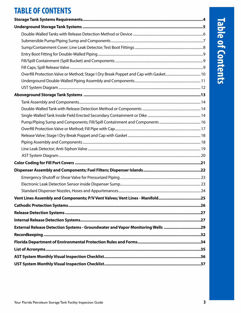
TABLE OF CONTENTSStorage Tank Systems Requirements...............................................................................................................4
Underground Storage Tank Systems ...............................................................................................................5
Double-Walled Tanks with Release Detection Method or Device ..................................................................................6
Submersible Pump/Piping Sump and Components ............................................................................................................7
Sump/Containment Cover; Line Leak Detector; Test Boot Fittings ................................................................................8
Entry Boot Fitting for Double-Walled Piping ...........................................................................................................................9
Fill/Spill Containment (Spill Bucket) and Components .......................................................................................................9
Fill Caps; Spill Release Valve ............................................................................................................................................................9
Overfill Protection Valve or Method; Stage I Dry Break Poppet and Cap with Gasket......................................... 10
Underground Double-Walled Piping Assembly and Components ............................................................................. 11
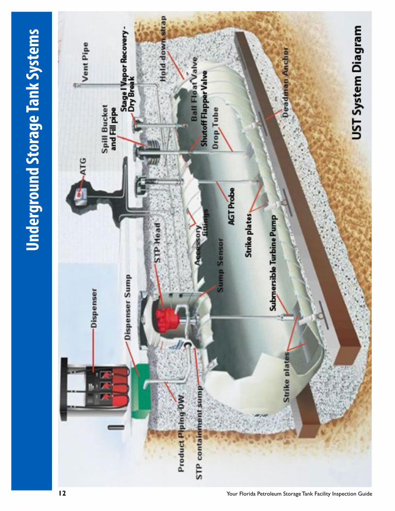
UST System Diagram ...................................................................................................................................................................... 12
Aboveground Storage Tank Systems ............................................................................................................13
Tank Assembly and Components .............................................................................................................................................. 14
Double-Walled Tank with Release Detection Method or Components .................................................................... 14
Single-Walled Tank Inside Field Erected Secondary Containment or Dike .............................................................. 14
Pump/Piping Sump and Components; Fill/Spill Containment and Components ................................................ 16
Overfill Protection Valve or Method; Fill Pipe with Cap .................................................................................................... 17
Release Valve; Stage I Dry Break Poppet and Cap with Gasket ..................................................................................... 18
Piping Assembly and Components .......................................................................................................................................... 18
Line Leak Detector; Anti-Siphon Valve .................................................................................................................................... 19
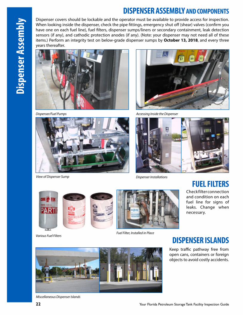
AST System Diagram ...................................................................................................................................................................... 20
Color Coding for Fill Port Covers ....................................................................................................................21
Dispenser Assembly and Components; Fuel Filters; Dispenser Islands .....................................................22
Emergency Shutoff or Shear Valve for Pressurized Piping .............................................................................................. 23
Electronic Leak Detection Sensor inside Dispenser Sump.............................................................................................. 23
Standard Dispenser Nozzles, Hoses and Appurtenances ................................................................................................ 24
Vent Lines Assembly and Components; P/V Vent Valves; Vent Lines - Manifold .......................................25
Cathodic Protection Systems ..........................................................................................................................26
Release Detection Systems .............................................................................................................................27
Internal Release Detection Systems ...............................................................................................................27
External Release Detection Systems - Groundwater and Vapor Monitoring Wells ..................................29
Recordkeeping .................................................................................................................................................32
Florida Department of Environmental Protection Rules and Forms ..........................................................34
List of Acronyms ...............................................................................................................................................35
AST System Monthly Visual Inspection Checklist .........................................................................................36
UST System Monthly Visual Inspection Checklist .........................................................................................37
Table of Contents

4 Your Florida Petroleum Storage Tank Facility Inspection Guide
STORAGE TANK SYSTEMS REQUIREMENTSThe Florida Department of Environmental Protection (FDEP) regulates the storage and operation of regulated substances that are stored in Underground Storage Tank (UST) systems or Aboveground Storage Tank (AST) systems throughout the State of Florida. USTs with capacities greater than 110 gallons and ASTs with capacities greater than 550 gallons are regulated and required to be registered with the FDEP.
FDEP or its designated county inspectors will visit your site to conduct compliance inspections periodically to verify these systems are operated and maintained according to code. Site access to the facility and individual storage tank systems and their components shall be provided for FDEP compliance and other follow-up inspections. This brochure provides guidance on UST and AST systems and their main components that are required to be maintained and monitored as part of the State regulatory inspection requirements.
Note:
Aboveground mineral acid storage tanks with individual capacities greater than 110 gallons containing hydrobromic acid (HBr), hydrochloric acid (HCL), hydrofluoric acid (HF), phosphoric acid (H3PO4) or sulfuric acid (H2SO4) are only subject to Rule 62-762.891, Florida Administrative Code (F.A.C.). Aboveground compression vessels and hazardous substance storage tanks with individual capacities greater than 110 gallons are only required to be registered with the FDEP.
Double-walled Fiberglass-coated Steel USTs during installation
Double-walled Fiberglass UST with Brine-filled Interstice
Double-walled Vertical Steel ASTs
Single-walled Steel AST Inside Concrete Secondary Containment
Stor
age T
ank S
yste
ms R
equi
rem
ents

Your Florida Petroleum Storage Tank Facility Inspection Guide 5
UNDERGROUND STORAGE TANK SYSTEMSStorage tank systems have three primary components: the tank, integral piping and fuel dispensing pump(s). All Underground Storage Tanks (UST) must be Double-Walled (DW) or installed within an FDEP approved secondary containment system. With the exception of dispenser islands and fueling dispenser pumps, most UST components are below grade and not readily visible or readily accessible. Site access to the facility and individual storage tank system and system components shall be provided for FDEP compliance inspections. The following system component photos or images are included to familiarize and assist the owner/operator with identifying critical components to be monitored.
TYPICAL DOUBLE-WALLED USTs
DW-Fiberglass UST Prior to Install DW-Fiberglass Coated Steel Composite USTs During Installation
DW-Steel Tank with Cathodic Protection DW-Steel Tank with Sacrificial Anodes Attached
DW-Fiberglass USTs On-site, Pending Installation DW-Fiberglass USTs During Installation
Underground Storage Tank Systems

6 Your Florida Petroleum Storage Tank Facility Inspection Guide
DOUBLE-WALLED TANKS WITH RELEASE DETECTION METHOD OR DEVICEA Release Detection (RD) method or device must be installed and monitored within the tank interstice (the space between the inner and outer tank walls) to detect a release and alert the operator. See Release Detection Systems Section (page 27) for options. On a monthly basis, but not exceeding 35 days, inspect and document the condition of any visible component of a storage tank system. For electronic release detection devices, inspect monthly, but not exceeding 35 days, for proper operation and maintain a record of the alarm history, sensor status, and testing results. Perform and maintain records of the annual operability test on the RD device to confirm it is operating in accordance with manufacturer’s specifications. Below are examples of UST systems with various interstitial RD devices. If connected to an electronic alarm module, an alarm may be triggered when the inner or outer tank wall is breached.
Facility owners/operators are required to file an Incident Notification Form within 72 hours if the system or component is damaged and may have caused a release or discharge to occur. If a discharge is confirmed, file a Discharge Reporting Form within 24 hours of discovery of the discharge. (See Forms on page 34.)
UST Hydrostatic RD SensorUST with Brine-filled Interstice Brine-filled Interstice RD Sensor
Dry Secondary Containment with Interstitial Sensor/Probe
Brine-filled Interstice Sump Probe
Sensor Cable
Non-discriminating Sensor
Discriminating Sensor
Steel Tanks Micro Sensor
Discriminating Sensor
Unde
rgro
und
Stor
age T
ank S
yste
ms

Your Florida Petroleum Storage Tank Facility Inspection Guide 7
SUBMERSIBLE PUMP/PIPING SUMP AND COMPONENTSThe pump/piping sump is typically the lowest point in the piping and connects on top of the UST, below grade, and typically houses the submersible turbine pump, RD sensors, electronic components, and associated pipe fittings and connections. To access the pump/piping sump, remove the manway sump cover with caution to avoid dropping it onto the sump containment cover, which may result in damages. Perform and document the following:
• Monthly, but not exceeding 35 days, check for liquid accumulation and sump integrity.
• Monthly, but not exceeding 35 days, visually inspect the pump head, pipe fittings and Line Leak Detector (LLD) for signs of corrosion, sweating and leaks. If monitored electronically, visually inspect every six (6) months.
• Perform a LLD operability test every 12 months to confirm the LLD functions as required.
• Perform an electronic sensor operability test every 12 months to confirm the sensor functions as required.
• Perform an integrity test on the pump/piping sumps by October 13, 2018, and every three years thereafter. Pump Sump Installation
UST Systems with Sump Manway Covers Opened for Inspection
Pump/Piping Sump Manway Cover Piping, Pump and LLD inside Sump Submersible Turbine Pumps (STP)
Underground Storage Tank Systems

8 Your Florida Petroleum Storage Tank Facility Inspection Guide
SUMP/CONTAINMENT COVERThe sump/containment cover must be fitted tightly to minimize the intrusion of storm water or groundwater into the sump containment, which can result in an accumulation of sufficient quantity to trip the release detection system alarm. Check for cracks or holes and after rain events confirm the sump cover is water tight. Liquids that accumulate in this area should be safely removed and must be properly disposed.
Sump Cover Closed Sump Cover Open
LINE LEAK DETECTOR This device is located on the submersible turbine pump and is designed to automatically detect, restrict or shutoff flow of fuel to the dispensers when a line leak is detected. There are two types of automatic Line Leak Detectors (LLD), mechanical or electronic. Perform the annual operability test on the LLD at intervals not exceeding 12 months in accordance with the manufacturer’s instructions to confirm the system is operating as designed.
Electronic LLDMechanical LLD
TEST BOOT FITTINGSThis component is installed at the piping terminus to allow testing of the piping interstitial integrity. Test Boots or Reducing Tees may be used to pressure test the outer wall piping. The boots must be pulled back from the secondary lines, and the reducing tee test port must be unplugged after lines have been tested unless the piping system is designed with a closed interstice and release detection is conducted within the closed interstice. If this is not done, any leakage into the outer wall piping will not flow into the sump to trip the sensor and alert a leak from the primary piping.Test Boot Installed, Pulled Back
After Testing
Test Boot
Unde
rgro
und
Stor
age T
ank S
yste
ms
Your Florida Petroleum Storage Tank Facility Inspection Guide 9
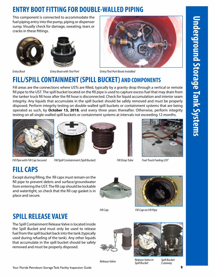
ENTRY BOOT FITTING FOR DOUBLE-WALLED PIPINGThis component is connected to accommodate the fuel piping entry into the pump, piping or dispenser sump. Visually check for damage, sweating, tears or cracks in these fittings.
Entry Boot Entry Boot with Test Port Entry/Test Port Boots Installed
FILL/SPILL CONTAINMENT (SPILL BUCKET) AND COMPONENTSFill areas are the connections where USTs are filled, typically by a gravity drop through a vertical or remote fill pipe to the UST. The spill bucket located on the fill pipe is used to capture excess fuel that may drain from the tanker truck fill hose after the fill hose is disconnected. Check for liquid accumulation and interior seam integrity. Any liquids that accumulate in the spill bucket should be safely removed and must be properly disposed. Perform integrity testing on double-walled spill buckets or containment systems that are being operated as such, by October 13, 2018, and every three years thereafter. Otherwise, perform integrity testing on all single-walled spill buckets or containment systems at intervals not exceeding 12 months.
Except during filling, the fill caps must remain on the fill pipe to prevent debris and surface/groundwater from entering the UST. The fill cap should be lockable and watertight, so check that the fill cap gasket is in place and secure.
Fill Pipe with Fill Cap Secured Fuel Truck Fueling USTFill/Spill Containment (Spill Bucket) Fill Drop Tube
FILL CAPS
Fill Cap Fill Cap on Fill Pipe
SPILL RELEASE VALVEThe Spill Containment Release Valve is located inside the Spill Bucket and must only be used to release fuel from the spill bucket back into the tank (typically used during refueling of the tank). Any other liquids that accumulate in the spill bucket should be safely removed and must be properly disposed.
Release Valve Release Valve in Spill Bucket
Spill Bucket Cutaway
Underground Storage Tank Systems

10 Your Florida Petroleum Storage Tank Facility Inspection Guide
OVERFILL PROTECTION VALVE OR METHODThis device or other approved method (such as a high level alarm system) is required on all USTs to prevent an overfill event during fuel deliveries. Depending on the device used, flow into the UST may be restricted or an alarm may sound at the 90 percent capacity and in general flow into the UST is stopped at the 95 percent capacity. Overfill protection devices must be tested every 12 months for proper operation.
Ball float valves may not be used when overfill protection is installed.
Ball Float or Vent Flow Restrictor; Installed
Automatic Tank Gauging (ATG) Probes Overfill High Level Alarm System Using Automatic Tank Gauging
Overfill Automatic Shutoff Flapper Valve
Ball Float Valve
STAGE I DRY BREAK POPPET AND CAP WITH GASKETThis component is used to return gasoline vapors back to the delivery truck tank compartment and prevents the release of gasoline vapors into the atmosphere. Press the spring loaded valve in the center for spring compression reaction and to check for a tight seal. Poppet caps should be in place at all times except when storage tanks are being fueled. Ensure the cap gasket is secure and cap fits tightly onto the dry break poppet.
Stage I Dry Break Poppet Dry Break Cutaway Vapor Recovery Poppet Cap
Fuel Delivery with Stage I EngagedStage I Vapor Recovery Color-coded Sump
Unde
rgro
und
Stor
age T
ank S
yste
ms

Your Florida Petroleum Storage Tank Facility Inspection Guide 11
UNDERGROUND DOUBLE-WALLED PIPING ASSEMBLY AND COMPONENTSAll underground piping in contact with soil must be double-walled or installed inside an FDEP approved secondary containment system. Pipes should slope back to USTs to ensure that, in the case of any line break, product will flow back towards the UST and pumps/piping sumps. It is unlikely pipes will be visible for inspection except for the pipe fittings within the pumps/piping sump. Check for tears and breaks on the Flex Pipe and fittings located inside the pumps/piping sump.
Double-walled Fiberglass Piping Layout
Primary Fiberglass Fuel Line/Piping
Double-walled Flexible Piping Layout Double-walled Flexible Primary Piping
UST System Piping/Dispenser Liner Installation
Flex Pipe Fitting in Dispenser Sump
Flex Pipe Fitting
Underground Storage Tank Systems
Flex Pipe Fitting in Pump/Piping Sump
12 Your Florida Petroleum Storage Tank Facility Inspection Guide
Unde
rgro
und
Stor
age T
ank S
yste
ms

Your Florida Petroleum Storage Tank Facility Inspection Guide 13
ABOVEGROUND STORAGE TANK SYSTEMSAll Aboveground Storage Tanks (AST) must be double-walled or installed within an impervious secondary containment. With the exception of connected underground piping, most storage tank components of ASTs are above grade and readily visible or accessible. Aboveground piping not in contact with soil is not required to have secondary containment unless the piping extends over water. Site access to the facility and individual storage tank system and system components shall be provided for FDEP compliance inspections. The following system component photos and images are included here to assist the owner/operator in identifying critical components to be monitored.
TYPICAL ASTs
Horizontal DW-AST Horizontal SW-AST within Secondary Containment
Vertical SW-AST within Secondary Containment
Sub-base DW-Emergency Generator AST
SW-AST with Dispenser within Secondary Containment
DW-AST with Dispenser within Containment
Aboveground Storage Tank Systems

14 Your Florida Petroleum Storage Tank Facility Inspection Guide
TANK ASSEMBLY AND COMPONENTSASTs must be installed on a sound foundation (e.g. reinforced concrete pad) that will provide the necessary support, strength and stability to withstand various environmental conditions. On a monthly basis, but not exceeding 35 days, visually inspect areas or components that can be inspected for any problems such as component corrosion or signs of a release. Record these monthly checks in a log to show that the inspections are being completed. Routine inspection will identify problems early, before they develop into serious issues, and will ensure the equipment works to reduce emissions and leaks.
DOUBLE-WALLED TANK WITH RELEASE DETECTION METHOD OR COMPONENTSDouble-walled ASTs must be equipped with a visual, mechanical or electronic Release Detection (RD) system located in the tank interstitial space (the space between the inner and outer tank walls) to detect a release and alert the operator of this incident. See Release Detection Systems Section (page 27) for options. On a monthly basis, but not exceeding 35 days, inspect the tank shell, pipes and fittings for leaks, usually demonstrated by uncontrolled corrosion/pitting or paint discoloration. Perform an annual operability test every 12 months on the RD system in accordance with the manufacturer’s instructions to confirm the system is operating as designed.
Facility owners/operators are required to file an Incident Notification Form within 72 hours if the system or component is damaged and may have caused a release or discharge to occur. If a discharge is confirmed, file a Discharge Reporting Form within 24 hours of discovery of the discharge. (See Forms on page 34.)
DW-AST with Spill Containment, Anti-siphon Valve and RD Mechanical RD Gauge
SINGLE-WALLED TANK INSIDE FIELD ERECTED SECONDARY CONTAINMENT OR DIKESingle-walled ASTs shall have a secondary containment dike that is constructed to contain 110 percent of the largest tank capacity volume and is structurally sound to withstand hydrostatic forces of the contained volume of the liquid stored. AST secondary containment must be constructed of impervious materials and be sealed and properly coated to prevent any fuel or sweating on the ground area around the secondary containment. All aboveground fuel storage tanks must be labeled (by name) as to the specific type of fuel that is being stored in each tank (e.g., diesel, gasoline, waste oil, etc.). ASTs located inside a dike area are subject to storm water accumulation which must be managed and properly disposed. Check accumulated storm water for sheen or floating product before disposing. RD requirements are met when you perform monthly inspection checks for the following and record your findings.
1. Check tank coating integrity.2. Check tank foundation and supports for cracks and signs of corrosion.3. Check secondary containment integrity.4. Inspect containment for liquid accumulation.5. Check drain valve area for leaks (must be lockable and secured when not in use).6. Check vent lines to ensure vent caps are in place.7. Check for proper dimensions of containment volume (at least 110 percent of the largest tank volume).8. Check roof integrity after a storm event for any leaks.
Abov
egro
und
Stor
age T
ank S
yste
ms

Your Florida Petroleum Storage Tank Facility Inspection Guide 15
SINGLE-WALLED TANK INSIDE FIELD ERECTED SECONDARY CONTAINMENT OR DIKE
Check Tank Coating and Secondary Containment Integrity Check Tank Foundation and Anchoring
Check Drain Valves for Leaks. Ensure they are Locked when Not in Use Check for Proper Secondary Containment Dimensions
Check Roof for Integrity for Leaks, Especially after a Storm Event Check Secondary Containment for Discharge or Liquid Accumulation
Aboveground Storage Tank Systems

16 Your Florida Petroleum Storage Tank Facility Inspection Guide
PUMP/PIPING SUMP AND COMPONENTS With the exception of an underground remote fill system or underground piping to dispensers or other endpoint equipment, pump sumps typically are not installed on ASTs. Suction or Submersible Turbine Pumps (STP) are used to deliver fuel to the dispensing or auxiliary equipment as needed. Suction pumps are typically located at the dispenser or auxiliary equipment (e.g., diesel power generator) while the STPs are located at and inside the AST.
AST with STP connection on top of the TankAST with Suction Pump at Dispenser
FILL/SPILL CONTAINMENT AND COMPONENTS Fill areas are the connections where ASTs are filled, sometimes under pressure through an aboveground vertical or remote fill pipe to the AST. Storage tanks that are loaded by trucks shall be installed with a spill containment system at each tank fill connection, except for tank fill connections located within dike field areas with secondary containment or within tank truck containment areas. The spill containment located at the fuel fill area is used to capture excess fuel that may drain from the tanker truck fill hose after the fill hose is disconnected. Check for liquid accumulation and interior seam integrity for corrosion and liquid tightness. Any liquids that accumulate in this area should be safely removed and must be properly disposed. Check for cracks or holes and after rain events to confirm the sump cover is water tight.
AST Spill Containment on Tank Top AST Remote Fill/Spill Containment
Miscellaneous Types of AST Spill Containment
Abov
egro
und
Stor
age T
ank S
yste
ms
Your Florida Petroleum Storage Tank Facility Inspection Guide 17
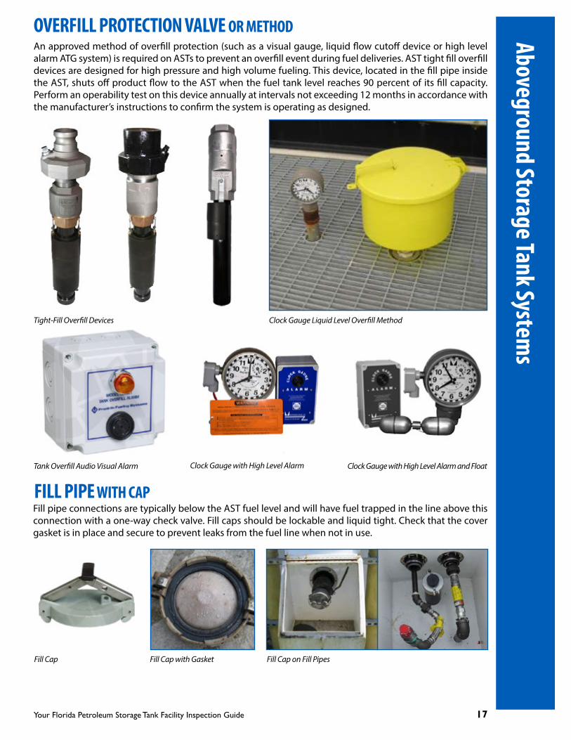
Tank Overfill Audio Visual Alarm Clock Gauge with High Level Alarm Clock Gauge with High Level Alarm and Float
OVERFILL PROTECTION VALVE OR METHODAn approved method of overfill protection (such as a visual gauge, liquid flow cutoff device or high level alarm ATG system) is required on ASTs to prevent an overfill event during fuel deliveries. AST tight fill overfill devices are designed for high pressure and high volume fueling. This device, located in the fill pipe inside the AST, shuts off product flow to the AST when the fuel tank level reaches 90 percent of its fill capacity. Perform an operability test on this device annually at intervals not exceeding 12 months in accordance with the manufacturer’s instructions to confirm the system is operating as designed.
Tight-Fill Overfill Devices Clock Gauge Liquid Level Overfill Method
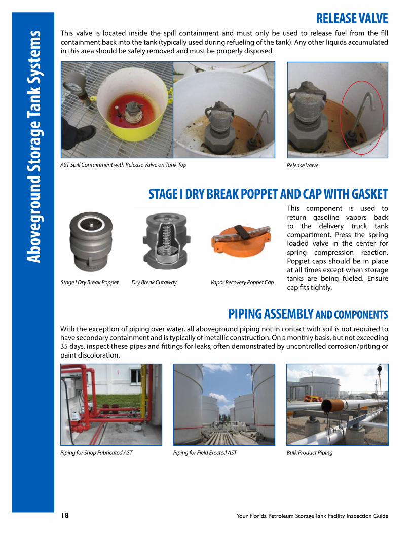
FILL PIPE WITH CAPFill pipe connections are typically below the AST fuel level and will have fuel trapped in the line above this connection with a one-way check valve. Fill caps should be lockable and liquid tight. Check that the cover gasket is in place and secure to prevent leaks from the fuel line when not in use.
Fill Cap Fill Cap with Gasket Fill Cap on Fill Pipes
Aboveground Storage Tank Systems
18 Your Florida Petroleum Storage Tank Facility Inspection Guide
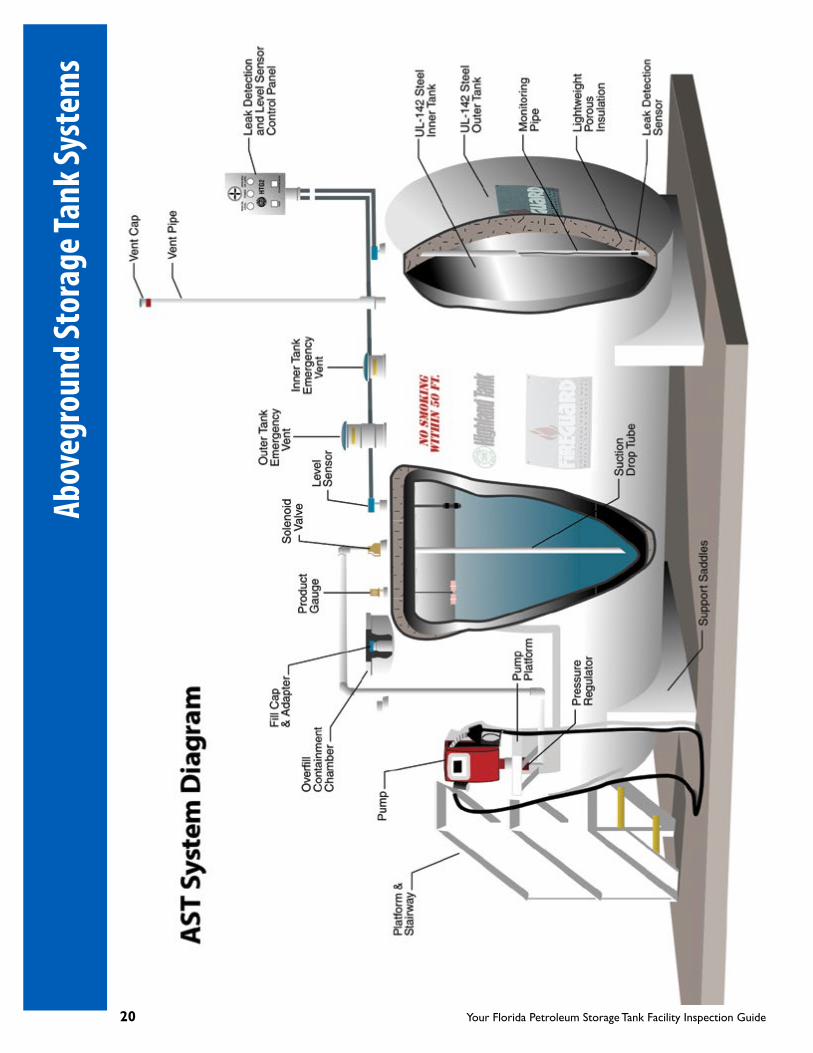
RELEASE VALVEThis valve is located inside the spill containment and must only be used to release fuel from the fill containment back into the tank (typically used during refueling of the tank). Any other liquids accumulated in this area should be safely removed and must be properly disposed.
AST Spill Containment with Release Valve on Tank Top Release Valve
STAGE I DRY BREAK POPPET AND CAP WITH GASKETThis component is used to return gasoline vapors back to the delivery truck tank compartment. Press the spring loaded valve in the center for spring compression reaction. Poppet caps should be in place at all times except when storage tanks are being fueled. Ensure cap fits tightly.
Stage I Dry Break Poppet Vapor Recovery Poppet Cap
PIPING ASSEMBLY AND COMPONENTSWith the exception of piping over water, all aboveground piping not in contact with soil is not required to have secondary containment and is typically of metallic construction. On a monthly basis, but not exceeding 35 days, inspect these pipes and fittings for leaks, often demonstrated by uncontrolled corrosion/pitting or paint discoloration.
Piping for Shop Fabricated AST Piping for Field Erected AST Bulk Product Piping
Dry Break Cutaway
Abov
egro
und
Stor
age T
ank S
yste
ms

Your Florida Petroleum Storage Tank Facility Inspection Guide 19
PIPING ASSEMBLY AND COMPONENTS
DW-semi-rigid Pipe Over Water Aboveground SW-pipe Transition to Underground DW-pipe
LINE LEAK DETECTORThe Line Leak Detector (LLD) is located on the Submersible Turbine Pump (STP) and is designed to automatically detect, restrict or shut off flow of fuel to the dispensers when a line leak is detected. There are two types of automatic LLDs, mechanical or electronic. All pressurized small diameter integral piping that is in contact with the soil must be installed with LLDs and must be located downstream from the anti-siphon or solenoid valve, as applicable. LLDs are not required for piping that is not in contact with the soil. The LLD must be tested annually at intervals not exceeding 12 months for operability in accordance with the manufacturer’s instructions to confirm the system is operating as designed.
Electronic LLD Mechanical LLD
ANTI-SIPHON VALVEAn anti-siphon valve must be installed when the storage tank produces a gravity head on small diameter piping positioned below the storage tank product level to prevent a release of product in the event of a pipe/fitting leak or pipe rupture.
Anti-siphon Valve with Isolation Ball Valve Anti-siphon with Isolation Ball Valve
Anti-siphon Valve
Aboveground Storage Tank Systems
20 Your Florida Petroleum Storage Tank Facility Inspection Guide
Abov
egro
und
Stor
age T
ank S
yste
ms

Your Florida Petroleum Storage Tank Facility Inspection Guide 21
COLOR CODING FOR FILL PORT COVERS
Hi-Grade (Premium) Fill Cover Mid-Grade Fill Cover Low-Grade Unleaded Fill Cover
Low Sulfur Diesel Fill Cover Used Oil Fill Cover High Sulfur Fill Cover
Stage I Dry Break Cover No. 1 Fuel Oil Fill Cover No. 2 Fuel Oil Fill Cover Kerosene Fill Cover
Fill ports, where USTs or ASTs are filled, require the fill covers be color-coded as illustrated below. This helps prevent accidental filling of the wrong fuel into the wrong tank. Ensure that the covers are maintained as required.
ALCOHOL-BASED FUELS
M85 Ethanol Fill Cover Hi-Grade Fill Cover Mid-Grade Fill Cover Low-Grade Fill Cover
Fill Port Covers
22 Your Florida Petroleum Storage Tank Facility Inspection Guide
DISPENSER ASSEMBLY AND COMPONENTSDispenser covers should be lockable and the operator must be available to provide access for inspection. When looking inside the dispenser, check the pipe fittings, emergency shut off (shear) valves (confirm you have one on each fuel line), fuel filters, dispenser sumps/liners or secondary containment, leak detection sensors (if any), and cathodic protection anodes (if any). (Note: your dispenser may not need all of these items.) Perform an integrity test on below-grade dispenser sumps by October 13, 2018, and every three years thereafter.
Dispenser/Fuel Pumps Accessing Inside the Dispenser
View of Dispenser Sump Dispenser Installations
FUEL FILTERSCheck filter connection and condition on each fuel line for signs of leaks. Change when necessary.
DISPENSER ISLANDSVarious Fuel Filters
Fuel Filter, Installed in Place
Keep traffic pathway free from open cans, containers or foreign objects to avoid costly accidents.
Miscellaneous Dispenser Islands
Disp
ense
r Ass
embl
y

Your Florida Petroleum Storage Tank Facility Inspection Guide 23
EMERGENCY SHUTOFF OR SHEAR VALVE FOR PRESSURIZED PIPING Shear valves are used to prevent the release of fuel in the event the dispenser is dislodged or knocked off its foundation. Check the valve lever and the connection to the bracket, as shown. There should be one shear valve for each fuel line.
Shear Valves Secured to BracketsEmergency Shut-off Shear Valves
Various Shear Valves Installed at Correct Height. Note Valve Anchoring to Dispenser Box
ELECTRONIC LEAK DETECTION SENSOR INSIDE DISPENSER SUMPCheck that the wire connections are secure. Check height and position of the sensor from the sump and secondary containment bottom, as per manufacturer’s instructions. The release detection system should alarm when there is a fuel leak or an excessive amount of liquid in the dispenser sump. Check for cracks and for an excessive amount of liquid in the sump. Liquid must be pumped out safely and properly disposed.
Discriminating Dispenser Sump Sensor
Dispenser Sump Sensor/CableDispenser Sump Sensor Placed Near Sump Bottom
Dispenser Assembly

24 Your Florida Petroleum Storage Tank Facility Inspection Guide
STANDARD DISPENSER NOZZLES, HOSES AND APPURTENANCESNozzles may develop leaks from constant use. Check for leaks and drips from the nozzle spout, hose and connections. Also check for excessive wear and cracking of the dispenser hoses.
Dispensers, Nozzles, Hoses and Appurtenances
Various Gasoline and Diesel Nozzles
Dispenser Hoses Hose Cutaway
Whip Hose Swivel-ends Hoses
Various Breakaways Swivel Breakaway Reconnectable Breakaways
Disp
ense
r Ass
embl
y

Your Florida Petroleum Storage Tank Facility Inspection Guide 25
VENT LINES ASSEMBLY AND COMPONENTSVent lines allow pressure within the tank to equalize when product is removed from or introduced into the tank. The Pressure-Vacuum (P/V) and standard vent valves are typically used at gasoline dispensing facilities. The P/V valves are required on gasoline UST/ASTs’ vent lines per Chapter 62-252, F.A.C., Gasoline Vapor Control, and the fire codes, as applicable. Vent Lines with Valves Installed Vent Valves Extend 12 feet Above Grade
PRESSURE/VACUUM OR REGULAR/STANDARD VENT VALVESThis valve must be in place at all times per Chapter 62-252, F.A.C., Gasoline Vapor Control, and the fire codes, as applicable. This also prevents debris from falling into the tank.
Standard vents installed on the top of vent pipes from underground or aboveground diesel fuel storage tanks are always open to the atmosphere to allow any pressure or vacuum in the tank to vent.
Pressure/Vacuum Vents
Standard Vents
STORAGE TANK VENT LINESEach vent line is associated with one underground tank unless manifolded. A P/V or regular vent valve must be in place for each vent line.
Note: Vent lines should extend a minimum of 12 feet above ground level, checked periodically and cleared of dust, rust or debris accumulation for proper functioning.
VENT LINES MANIFOLDVent lines may be manifolded where this type of assembly requires only one P/V or regular vent valve.
Aboveground Manifold Underground Manifold
Vent Lines Assembly

26 Your Florida Petroleum Storage Tank Facility Inspection Guide
CATHODIC PROTECTION SYSTEMSCathodic Protection (CP) is used to control the corrosion of metallic storage tank systems by connecting the metal components to be protected to a more easily corroded sacrificial anode. The sacrificial anode then corrodes instead of the protected components. For pipelines or field erected, steel ASTs in contact with soil, where sacrificial anodes may not be adequate, an external electrical power source (rectifier or impressed current) is used to provide sufficient current to protect the metal components.
Cathodic protection test stations are typically required and located close to the structure that is protected to allow periodic testing to confirm adequate corrosion protection is maintained on the system. Check the wire connection to the anode from the steel tank or pipe.
Cathodic protection systems must be tested by a corrosion professional. Factory installed galvanic anode systems are to be tested every three years. Impressed current systems typically have an Amp and Volt meter console that maintains a steady voltage-current supply to the protected structure. Check Volt-Amp readings every 60 days to confirm designed output readings are maintained. Impressed current systems and field installed sacrificial anode systems must be tested annually.
Galvanic CP System with Sacrificial Anodes Attached
Impressed Current CP System
CP Test Stations
Impressed Current Rectifier with Voltmeter and Ammeter Sacrificial Anode Install
Cath
odic
Prot
ectio
n Sy
stem
s

Your Florida Petroleum Storage Tank Facility Inspection Guide 27
RELEASE DETECTION SYSTEMSAll facilities are required to have internal or external release detection equipment or methods for their storage tank systems. On a monthly basis, but not exceeding 35 days, inspect and document the condition of any visible component of a storage tank system. Release detection, interstitial monitoring or overfill protection equipment or devices are required to have an annual operability test to determine if these devices are functioning as designed and in accordance with the manufacturer’s specification. (Please refer to Chapter 62-761 and Chapter 62-762, Florida Administrative Code, for more information.) Existing UST systems that store fuel solely for use by emergency power generators must meet release detection requirements by October 13, 2018.
Facility owners/operators are required to file an Incident Notification Form within 72 hours if the system or component is damaged and may have caused a release or discharge to occur. If a discharge is confirmed, file a Discharge Reporting Form within 24 hours of discovery of the discharge. (See Forms on page 34.) Following are various types of Internal and External Release Detection systems used.
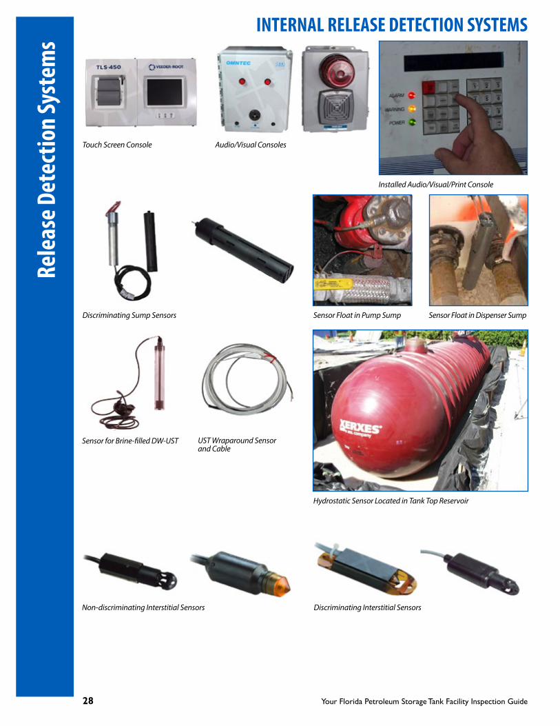
INTERNAL RELEASE DETECTION SYSTEMSAn internal release detection system or method is designed and operated within the storage tank system to alert the owner/operator of a release or incident before the regulated substance stored is released or discharged to the environment. Internal release detection systems may be monitored via visual, mechanical, manual or electronic means to detect a release into the tank/pipe secondary containment or interstice. Visual or mechanical systems may use a float gauge, dip-stick or other visual means to monitor the interstice.
Visual, Mechanical or Manual Monitoring Release Detection Components Typically Used in ASTs
AST Float Gauge Installed Measuring Stick Visual monitoring
Electronic Interstitial Monitoring Typically Used in AST and UST Systems
Currently, there are electronic systems that provide continuous, intermittent or on-demand displays or printouts of operating and alarm status records. These may include in-line leak detector monitoring, pipe/dispenser sump monitoring, DW-UST/AST interstitial release detection monitoring and test history. Electronic interstitial monitoring systems detect product that leaks from the primary containment towards an interstitial monitor or probe/sensor located in the lowest level between the primary and secondary containment walls. Electronic interstitial monitoring systems may also detect water that enters the interstice through a breach in the secondary containment.
Release Detection Systems
28 Your Florida Petroleum Storage Tank Facility Inspection Guide
INTERNAL RELEASE DETECTION SYSTEMS
Touch Screen Console Audio/Visual Consoles
Installed Audio/Visual/Print Console
Discriminating Sump Sensors Sensor Float in Pump Sump Sensor Float in Dispenser Sump
Sensor for Brine-filled DW-UST UST Wraparound Sensor and Cable
Hydrostatic Sensor Located in Tank Top Reservoir
Non-discriminating Interstitial Sensors Discriminating Interstitial Sensors
Rele
ase D
etec
tion
Syst
ems

Your Florida Petroleum Storage Tank Facility Inspection Guide 29
INTERNAL RELEASE DETECTION SYSTEMSGeneral System Checks and Recordkeeping for Release Detection
• Check any component thatcan be visually inspected monthly, but not exceeding 35 days, unless equipped with an electronic sensor. If equipped with an electronic sensor, visually inspect every six (6) months and record your findings.
• Electronic, mechanical orvisual interstitial monitoring must be conducted for all DW-USTs, DW-ASTs and DW-underground piping.
• All release detection devicesshall be tested annually at intervals not exceeding 12 months to ensure proper operation in accordance with manufacturer’s specifications.
UST RD Sensor Located at Low End of Interstice
UST with Brine-filled RD Monitor
EXTERNAL RELEASE DETECTION SYSTEMS - GROUNDWATER AND VAPOR MONITORING WELLS
UST Vapor and/or Groundwater Monitoring Wells
External release detection systems monitor the presence of regulated substances in groundwater or soil that is in contact with the storage tank system. This type of release detection may be used only at existing facilities with single-walled USTs that are installed within an FDEP approved synthetic membrane liner or existing bulk product storage facility with specific FDEP approval. If you have Monitoring Well(s) (MW), it/they must be checked monthly, but not exceeding 35 days, for visible sheen, floating product or electronic alarms (when used) and the results recorded. Inspectors will always look for these results.
Release Detection Systems

30 Your Florida Petroleum Storage Tank Facility Inspection Guide
EXTERNAL RELEASE DETECTION SYSTEMS - GROUNDWATER AND VAPOR MONITORING WELLS
Compliance Monitoring Well, Casing and Cover
(Black triangle on white cover).
MW Casings, Covers Installed MW with Color-coded Cover Bailing the MW
Compliance/Monitoring Well Containment with Grouting at Bottom
Routinely check grouting with a screwdriver or equivalent to ensure the grouting is intact. (Solid grouting is necessary to prevent surface runoff or spills from entering the soil through the well containment area.)
Compliance/Monitoring Well with Lockable Cap
Well cap must be kept locked or secured with lock or clips. Lock keys must be available onsite. The cap must be watertight. Provide suitable warning signs to fuel delivery drivers to prevent accidental fuel filling, e.g. MW - DO NOT FILL.
Installed MW with Grout Intact
Various Compliance/Monitoring Well Caps Cap in Place
Compliance/Monitoring Well Pipe
This pipe must be a minimum of at least one inch above the surface of the grouting (to help prevent standing contaminated liquid from entering into the well when the cap is removed).
MW Slotted Pipe
Exte
rnal
Rel
ease
Det
ectio
n

Your Florida Petroleum Storage Tank Facility Inspection Guide 31
EXTERNAL RELEASE DETECTION SYSTEMS - GROUNDWATER AND VAPOR MONITORING WELLSCompliance or Monitoring Well Acrylic Bailer with Cord
Keep the bailer and cord clean. When sampling wells, care should be taken if one well has signs of contamination (otherwise, wells will be cross contaminated). Bailers should be cleaned between each well sampling. A disposable bailer may be used.
Compliance or Monitoring Well Discriminating Electronic Probe
This system is designed to differentiate product or contamination from groundwater and/or background levels. Check the integrity of wires and connections.
Visual Check for Sheen or Free Floating Product
Acrylic Bailer/Cord
Assessment/Monitoring Well
Assessment wells (similar to MW in design) are installed and used to collect, monitor and analyze groundwater samples for the presence of contaminants of concern. Assessment wells may be located onsite at locations greater than 10 feet from the storage tank system to track contaminant levels and groundwater flow as required. Assessment wells are differentiated by a solid white circle on a black cover.
Old Discriminating Electronic Probe Pulled Out of Well, Pending Replacement
Assessment Well Compliance Well
External Release Detection

32 Your Florida Petroleum Storage Tank Facility Inspection Guide
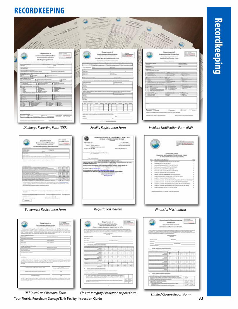
RECORDKEEPING
IT’S GOOD FOR YOUR BUSINESS AND IT SAVES INSPECTION TIME!
Regulations require owners/operators to maintain certain records about their storage tank system for inspection. Inspectors will ask to see these records.
DISPLAY THE FOLLOWING DOCUMENTS WHERE EVERYONE CAN SEE THEM
• The current FDEP Registration Placard. Remember to check the placard for the proper address. The placard is issued annually following payment of the registration fees.
• Currentlocalgovernmentpermit(s),ifapplicable.
KEEP THE FOLLOWING RECORDS AT THE STORAGE TANK FACILITY ON FILE FOR EASY ACCESS AND REVIEW
Keep these Records for At Least Three Years
• Allmonthlyvisualinspectionresultsoftheconditionofanystoragetanksystemcomponentthatcanbe visually inspected and that contains, transfers or stores regulated substances.
• Electronicreleasedetectionequipmentmonthlyfunctionchecks.
• Alltestdataandresultsgatheredduringannualoperabilitytestsandintegritytests.
• Repair,operationandmaintenancerecords.
• Recordsofthetypesoffuelsstoredpertank.
Keep these Records until Storage Tank System Closure
• Manufacturer’sinstructionsforoperation,maintenanceandtestingreleasedetectionequipment.
• Demonstratingmethodsoffinancialresponsibility.
• DRF,INFandresultsofallincidentinvestigations.
• Installation,maintenance,inspectionsandtestingofcorrosionandcathodicprotectionsystems.
• Storagesysteminstallations,replacements,recertificationandupgrades.
• Closure integrity report, closure reportor limitedclosure report, and releasedetection inspectionreport for out-of-service storage tank systems.
• Survey drawings of installed or relocated storage tank/piping systems signed and sealed by aProfessional Engineer or Professional Land Surveyor licensed in the state of Florida.
• RecordsofcurrenttrainingcertificatesfordesignatedClassA,B,andCoperatorsshallbemaintainedfor as long as the operators are designated for that facility.
• Recordsdocumentingcompliancewithcompatibilityofstoragetanksystemsandsystemcomponentsstoring regulated substances containing ethanol blends greater than 10 percent and biodiesel blends greater than 20 percent, as required.
Note: Facility operators must complete training and secure certification, no later than October 13, 2018, as required, to ensure the proper operation and maintenance of the storage tank system.
Reco
rdke
epin
g
Your Florida Petroleum Storage Tank Facility Inspection Guide 33
RECORDKEEPING
Discharge Reporting Form (DRF) Facility Registration Form Incident Notification Form (INF)
Equipment Registration Form Registration Placard Financial Mechanisms
UST Install and Removal Form Closure Integrity Evaluation Report Form Limited Closure Report Form
Recordkeeping

34 Your Florida Petroleum Storage Tank Facility Inspection Guide
FLORIDA DEPARTMENT OF ENVIRONMENTAL PROTECTION RULES AND FORMS
The following Rules and associated Forms may be accessed at the FDEP website: https://floridadep.gov/waste/permitting-compliance-assistance/content/storage-tank-system-rules-forms-and-reference
Rules
Chapter 62-761, F.A.C. Underground Storage Tank Systems (USTs)
» Rule Text
Chapter 62-762, F.A.C. Aboveground Storage Tank Systems (ASTs)
» Rule Text
Rule Forms
Underground Storage Tanks Systems
» Discharge Report Form» Facility Registration Form» Financial Mechanisms Form» Alternative Requirement or Procedure Form» UST Installation and Removal Form» Incident Notification Form» Closure Integrity Evaluation Report Form» Limited Closure Report Form» Equipment Registration Form» UST Closure Site Check Process Flowchart» Instructions for Conducting a Site Check During UST Closure
Aboveground Storage Tanks Systems
» Discharge Report Form» Facility Registration Form» Alternative Requirement or Procedure Form» Incident Report Form» Closure Integrity Evaluation Report Form» Limited Closure Report Form» Equipment Registration Form» Containment and Integrity Plan Certification Form» AST Closure Site Check Process Flowchart» Instructions for Conducting a Site Check During AST Closure
Self Service Registration Online
Storage Tank Registration Electronic Self Service Application (ESSA) Portal
Suggested AST and UST Monthly Checklists (Pages 36-37)
Flor
ida D
epar
tmen
t of E
nviro
nmen
tally
Pro
tect
ion
Rule
s and
Form
s

Your Florida Petroleum Storage Tank Facility Inspection Guide 35
ATG Automatic Tank GaugingAST Aboveground Storage TankCP Cathodic ProtectionDRF Discharge Report FormDW Double-WalledF.A.C. Florida Administrative CodeFDEP Florida Department of Environmental ProtectionINF Incident Notification FormLLD Line Leak DetectorMW Monitoring WellP/V Pressure/VacuumRD Release DetectionSTP Submersible Turbine PumpSW Single-WalledUST Underground Storage Tank
List of Acronyms
LIST OF ACRONYMS

36 Your Florida Petroleum Storage Tank Facility Inspection Guide
Facility Nam
e: ________________________
Facility ID: ___________________________
Yes
No
N/A
Initials
Commen
ts
Additio
nal Com
men
ts:
Piping
exterior n
ot corrode
d or dam
aged
Shear v
alves p
rope
rly ancho
red
Sump clean, empty, and
has no water, p
rodu
ct or d
ebris
Overfill alarm
s fun
ctioning
prope
rly
Piping
Second
ary Co
ntainm
ent
Containm
ent n
ot dam
aged
Liqu
id re
moved
from
inside
con
tainmen
t area
Drain valve
is closed, se
cured an
d no
t leaking
Clean, empty, and
no water, p
rodu
ct or d
ebris
Piping
not in
con
tact with
soil/de
bris
Hoses, n
ozzles and
breakaw
ays n
ot leaking or loose
Piping
maintaine
d, not corroding
or leaking
Sensor is in
correct position
Piping
not in
con
tact with
soil/de
bris
Dispe
nser
Anti‐siph
on valve
in working
order
Tank
Tank
#________
Type: SW in
second
ary containm
ent _
_____ DW______
Date_________
Ye
ar__________
AST SYSTEM
Stan
dards C
hecklist
Tank
exterior m
aintaine
d, not corrode
d or dam
aged
Fill Po
rt/Spill Bu
cket
Fill cover is in good
con
ditio
n an
d prop
erly color cod
edFill cap is tightly
sealed
, gasket is in good
con
ditio
nClean, empty, no water, p
rodu
ct or d
ebris
Overfill protection metho
d check
Fittings not kinked, cracked
, torn, or leaking
AST System
Mon
thly Visua
l Inspe
ction Ch
ecklist
Release Detectio
nElectron
ic interstitial m
onito
ring status not in
alarm
Visual interstitial m
onito
ring (Krueger gau
ge, stick, etc.)
Electron
ic m
onito
ring system
che
ck

Your Florida Petroleum Storage Tank Facility Inspection Guide 37
UST System M
onthly Visua
l Inspe
ction Ch
ecklist
Facility Nam
e:____________
Mon
th___________________ Year_____________________
Facility ID:_______________
Tank
#___________________ Type: DW____SW
inside
a line
r____C
atho
dic protectio
n_____
Yes
No
N/A
Dispe
nser
Hoses, n
ozzles and
breakaw
ays n
ot leaking or loose
Shear v
alves p
rope
rly ancho
red an
d secure
Sump clean, empty, no water, p
rodu
ct or d
ebris
Sump pe
netrations, entry boo
ts m
aintaine
d
Overfill protection metho
d presen
tOverfill alarm
s fun
ctioning
prope
rly
Piping
not in
con
tact with
soil
Fill Po
rt/Spill Bu
cket
Drop tube
in place
Cover in good
con
ditio
n an
d prop
erly color cod
ed
Additio
nal Com
men
ts:
Clean, empty, no water, p
rodu
ct or d
ebris
Sump ha
s no cracks or b
ulges
Piping
not corroding, leaking, kinked or sw
ellin
gSump lid
and
gasket in good
con
ditio
n
Stage‐I V
apor Recovery
Release Detectio
n
Clean, empty, no water, p
rodu
ct or d
ebris
Fill caps tightly
sealed
& gasket in good
con
ditio
nFill cover in good
con
ditio
n an
d prop
erly color cod
ed
Cathod
ic Protection System
‐ Im
pressed Cu
rren
tAM
P read
ing with
in design range
(value
in com
men
ts)
UST System
Stan
dards C
hecklist
Test boo
t pulled ba
ck or shrad
er valve
stem
removed
Cover in good
con
ditio
n
Sensor in
correct position
Containm
ent S
ump
Fittings not kinked, cracked
, torn, or leakin g
Electron
ic m
onito
ring system
status che
ckVisual interstitial m
onito
ring; vacuu
m, stick
(value
in com
men
ts)
Electron
ic interstitial m
onito
ring status not in
alarm
Initials
Commen
ts
Piping
has no leaks, not in
con
tact with
soil
Volta
ge re
ading with
in design range (
value in com
men
ts)
Plun
ger fun
ctioning
prope
rlyNo sw
ellin
g or cracks
Is th
e system
runn
ing
Dry break pop
pet cap
prope
rly se
aled
Popp
et is tightly
sealed moves freely whe
n de
pressed
Sensor correct position
Piping
not corroding
or leaking
Fittings not kinked, cracked
, torn, or leakin g

38 Your Florida Petroleum Storage Tank Facility Inspection Guide
Note
s

Your Florida Petroleum Storage Tank Facility Inspection Guide 39
This handbook is provided as a general guide. For specific regulation requirements, informational videos, FDEP/Local county contact lists and this publication in Spanish
refer to the website; Esta publicación está disponible en español en la siguiente página web: https://floridadep.gov/waste/permitting-compliance-assistance/
content/storage-tank-compliance
REMEMBERThe State’s economic engine is driven by the State’s ecological engine,
so help protect our ground and drinking water by properly maintaining your storage tank system.
This public document was promulgated at a cost of $2,480.00, or $2.480 per copy, to inform owners/operators about storage tank facilities inspections.
Revised 10/2017
©2016 by Broward County for the Florida Department of Environmental Protection
Printed on recycled paper