Embed Size (px)
Citation preview

1

2
Contents Warnings and Precautions ................................................................................................................................................. 5
Warranty ........................................................................................................................................................................... 5
Standard Warranty ........................................................................................................................................................ 5
Two Year Warranty ........................................................................................................................................................ 6
Disposal ............................................................................................................................................................................. 6
Packing List ........................................................................................................................................................................ 6
Front Panel ........................................................................................................................................................................ 7
Rear Panel ......................................................................................................................................................................... 7
Hardware Connection Setup ............................................................................................................................................. 8
Connection of the SE-1200MU and PC to ROUTER ........................................................................................................ 8
Menu Select....................................................................................................................................................................... 9
SETUP Key Functions ..................................................................................................................................................... 9
Setting the Resolution ............................................................................................................................................... 9
Software Upgrade .................................................................................................................................................... 10
Import – Export ....................................................................................................................................................... 11
INPUTS Key Functions .................................................................................................................................................. 19
Setting Video Inputs ................................................................................................................................................ 19
OUTPUTS Key Functions .............................................................................................................................................. 21
Setting Video Outputs ............................................................................................................................................. 21
Setting MultiViewer ................................................................................................................................................. 21
Setting GPI Out ........................................................................................................................................................ 22
Setting Streamer ...................................................................................................................................................... 22
AUDIO Key Functions ................................................................................................................................................... 25
HOME Key Functions ................................................................................................................................................... 26
ME Trans .................................................................................................................................................................. 26
DSK Trans ................................................................................................................................................................. 26
FTB Trans ................................................................................................................................................................. 26
WIPE Key Functions ..................................................................................................................................................... 27
Wipe ........................................................................................................................................................................ 28
Wipe Border ............................................................................................................................................................ 28
Wipe Shade.............................................................................................................................................................. 29
Wipe Position .......................................................................................................................................................... 30
STILLS Key Functions .................................................................................................................................................... 31
Still Load .................................................................................................................................................................. 31
Grab and Save .......................................................................................................................................................... 32
Delete ...................................................................................................................................................................... 32
KEYER Key Functions .................................................................................................................................................... 33
3
Keyer Control ........................................................................................................................................................... 33
Keyer Matte ............................................................................................................................................................. 33
Luma Key Quick Set Up ............................................................................................................................................ 34
DSK1 and DSK2 Quick Setup .................................................................................................................................... 35
SE-1200 MU Keying layers ....................................................................................................................................... 36
CHROMA Key Functions ............................................................................................................................................... 37
Overview ................................................................................................................................................................. 37
Chroma Matte ......................................................................................................................................................... 38
Chroma Key Ctrl ....................................................................................................................................................... 39
Color Spill ................................................................................................................................................................. 39
Chroma Key Quick Setup ......................................................................................................................................... 40
MASK Key Functions .................................................................................................................................................... 42
MATTE Key Functions .................................................................................................................................................. 43
FREEZE Key Functions .................................................................................................................................................. 44
Freeze – Still ............................................................................................................................................................ 45
P IN P Key Functions .................................................................................................................................................... 47
PIP Position .............................................................................................................................................................. 47
PIP Border ................................................................................................................................................................ 48
PIP Crop ................................................................................................................................................................... 48
USER Key Functions ..................................................................................................................................................... 49
Storing an user setup to a user memory slot ........................................................................................................... 49
Labelling an existing User memory slot ................................................................................................................... 50
Loading a previously saved User Setup .................................................................................................................... 50
Deleting a User Setup .............................................................................................................................................. 52
Sources Panel .................................................................................................................................................................. 53
AUX BUS ...................................................................................................................................................................... 53
PROGRAM.................................................................................................................................................................... 53
PRESET ......................................................................................................................................................................... 53
Transition ........................................................................................................................................................................ 54
Transition Panel ........................................................................................................................................................... 54
Transition Modes ..................................................................................................................................................... 54
Previewing a selected transition .............................................................................................................................. 54
Transition Controls Panel ............................................................................................................................................ 55
Key 1 and Key 2........................................................................................................................................................ 55
BGND – Background ................................................................................................................................................ 55
PRIORITY Key Function ............................................................................................................................................ 56
Rev and Nrm (NORM) / Rv (REV) buttons ................................................................................................................ 56
DSK TRANS Panel ......................................................................................................................................................... 56

4
FTB Key Function ......................................................................................................................................................... 57
Keyer Controls Panel ....................................................................................................................................................... 57
Matte Key Function ..................................................................................................................................................... 57
Lin Key Function .......................................................................................................................................................... 57
Top Key Function ......................................................................................................................................................... 57
Self Key Function ......................................................................................................................................................... 57
Split Key Function ........................................................................................................................................................ 57
Specifications ............................................................................................................................................................... 61

5
Warnings and Precautions
1. Read all of these warnings and save them for later reference. 2. Follow all warnings and instructions marked on this unit. 3. Unplug this unit from the wall outlet before cleaning. Do not use liquid or aerosol cleaners. Use a damp cloth for
cleaning. 4. Do not use this unit in or near water. 5. Do not place this unit on an unstable cart, stand, or table. The unit may fall, causing serious damage. 6. Slots and openings on the cabinet top, back, and bottom are provided for ventilation. To ensure safe and reliable
operation of this unit, and to protect it from overheating, do not block or cover these openings. Do not place this unit on a bed, sofa, rug, or similar surface, as the ventilation openings on the bottom of the cabinet will be blocked. This unit should never be placed near or over a heat register or radiator. This unit should not be placed in a built-in installation unless proper ventilation is provided.
7. This product should only be operated from the type of power source indicated on the marking label of the AC adapter. If you are not sure of the type of power available, consult your Datavideo dealer or your local power company.
8. Do not allow anything to rest on the power cord. Do not locate this unit where the power cord will be walked on, rolled over, or otherwise stressed.
9. If an extension cord must be used with this unit, make sure that the total of the ampere ratings on the products plugged into the extension cord do not exceed the extension cord rating.
10. Make sure that the total amperes of all the units that are plugged into a single wall outlet do not exceed 15 amperes.
11. Never push objects of any kind into this unit through the cabinet ventilation slots, as they may touch dangerous voltage points or short out parts that could result in risk of fire or electric shock. Never spill liquid of any kind onto or into this unit.
12. Except as specifically explained elsewhere in this manual, do not attempt to service this product yourself.Opening or removing covers that are marked “Do Not Remove” may expose you to dangerous voltage points or other risks, and will void your warranty. Refer all service issues to qualified service personnel.
13. Unplug this product from the wall outlet and refer to qualified service personnel under the following conditions: a. When the power cord is damaged or frayed; b. When liquid has spilled into the unit; c. When the product has been exposed to rain or water; d. When the product does not operate normally under normal operating conditions. Adjust only those
controls that are covered by the operating instructions in this manual; improper adjustment of other controls may result in damage to the unit and may often require extensive work by a qualified technician to restore the unit to normal operation;
e. When the product has been dropped or the cabinet has been damaged; f. When the product exhibits a distinct change in performance, indicating a need for service.
Warranty
Standard Warranty
Datavideo equipment is guaranteed against any manufacturing defects for one year from the date of purchase.
The original purchase invoice or other documentary evidence should be supplied at the time of any request for repair under warranty.
Damage caused by accident, misuse, unauthorized repairs, sand, grit or water is not covered by this warranty.
All mail or transportation costs including insurance are at the expense of the owner.
All other claims of any nature are not covered.
Cables & batteries are not covered under warranty.
Warranty only valid within the country or region of purchase. Your statutory rights are not affected.

6
Two Year Warranty
All Datavideo products purchased after 01-Oct.-2008 qualify for a free one year extension to the standard Warranty, providing the product is registered with Datavideo within 30 days of purchase. For information on how to register please visit www.datavideo.com or contact your local Datavideo office or authorized Distributors
Certain parts with limited lifetime expectancy such as LCD Panels, DVD Drives, Hard Drives are only covered for the first 10,000 hours, or 1 year (whichever comes first).
Any second year warranty claims must be made to your local Datavideo office or one of its authorized Distributors before the extended warranty expires.
Disposal
For EU Customers only - WEEE Marking.
This symbol on the product indicates that it will not be treated as household waste. It must
be handed over to the applicable take-back scheme for the recycling of Waste Electrical and
Electronic Equipment. For more detailed information about the recycling of this product, please
contact your local Datavideo office.
Packing List The following items should be included in the box. If any items are missing please contact your supplier.
1 x SE-1200 Main Unit
1 x SE-1200 MU Quick Start Guide
1 x Accessory List

7
Front Panel
Power Switch Switches the SE-1200 MU power ON / OFF.
Rear Panel
Video IN The SE-1200 MU is equipped with six video input channels. Video Input set is comprised of four SDI connectors and two HDMI ports.
Video OUT HDMI 1: Multi-View Outputs HDMI 2: Output for engineering debugging SDI 1 / SDI 2: SE-1200 MU is capable of achieving multi-view monitoring by connecting two multi-view monitors to the two SDI ports. The two HDMI outputs can be used for monitoring video in a number of different configurations.
Audio Input Supports four channels XLR Balanced Audio Input.
Ethernet Ports For connection of the Main Unit to the PC such that the SE-1200 MU can be remotely controlled on a graphical user interface.
RS-232 For remote control interface (TBD).
TALLY Output The SE-1200 MU Tally Output Port provides bi-color tally information (Red and Yellow); Red indicates On-Air and Yellow indicates next camera source.
DC IN Connect the supplied DC 12V PSU to this socket. The connection can be secured by screwing the outer fastening ring of the DC In plug to the socket.
Grounding Terminal When connecting this unit to any other component, make sure that it is properly grounded by connecting this terminal to an appropriate point. When connecting, use the socket and be sure to
use wire with a cross-sectional area of at least 1.0 mm2
.

8
Hardware Connection Setup
Connection of the SE-1200MU and PC to ROUTER Use the Ethernet cable to connect SE-1200 Main unit and PC to a router. The user can either set the IP address of the PC to
192.168.1.100 or configure the PC to DHCP mode in which the IP address is dynamically assigned by the router. The SE-1200 Main
unit has a default IP address of 192.168.1.101. Make sure all devices connected to the router are in the same IP domain as the
router (e.g. 192.168.1.X). After all network settings are configured, the PC and the SE-1200MU can thus communicate across
the network. Please contact the Datavideo local office should you require further assistance.

9
Menu Select Before starting to use the SE-1200 MU, the user should locate the MENU SELECT panel on the PC Control Panel and configure the
basic settings.
SETUP Key Functions
Setting the Resolution
1. There are six standard resolutions available on the SE-1200 MU. To set the resolution, the user should first click the Setup
button on the MENU SELECT panel.
2. Click on Standard to select the desired resolution
3. Select the desired resolution from the following list:
Click the up/down arrows to scroll through the resolution list and click the desired resolution. After the desired resolution is selected, the list should automatically disappear, leaving the selected standard resolution displayed at bottom left hand corner of the screen. The connected monitors should now identify and sync with the new resolution output sent from the switcher. The Video Standards supported are:
1920x1080i 60
1920x1080i 59.94
1920x1080i 50
1280x720p 60
1280x720p 59.94

10
1280x720p 50
After the new resolution is selected, click “Save Setup” (Step 2) to save the new setting to the device.
Software Upgrade
The SE-1200 MU also allows the user to perform software upgrade. The software upgrade procedure is outlined as follows:
1. Click the Setup button on the MENU SELECT panel.
2. Click the “Software Upgrade”
3. Click “Upgrade Processor”
4. Wait till the “Please Wait” prompt window disappear
11
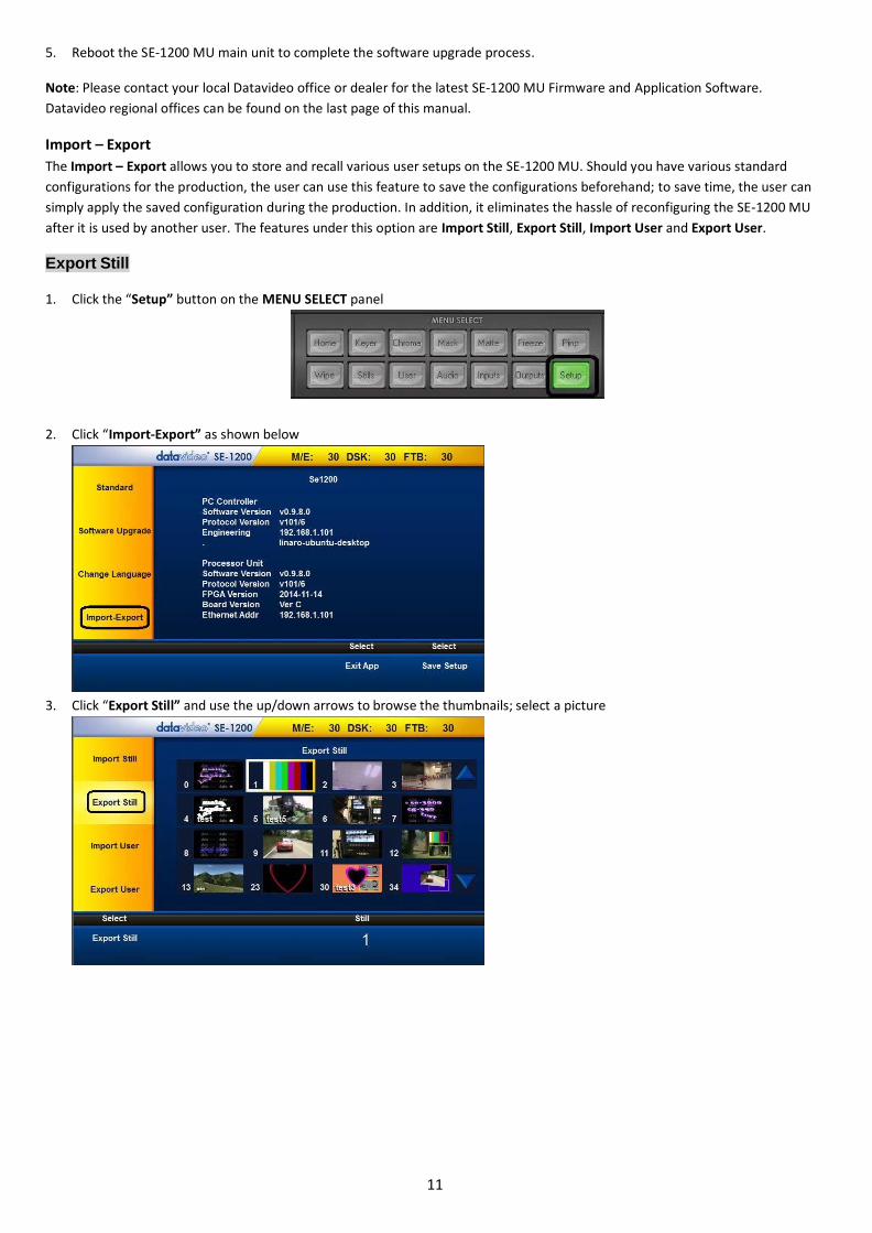
5. Reboot the SE-1200 MU main unit to complete the software upgrade process.
Note: Please contact your local Datavideo office or dealer for the latest SE-1200 MU Firmware and Application Software.
Datavideo regional offices can be found on the last page of this manual.
Import – Export
The Import – Export allows you to store and recall various user setups on the SE-1200 MU. Should you have various standard
configurations for the production, the user can use this feature to save the configurations beforehand; to save time, the user can
simply apply the saved configuration during the production. In addition, it eliminates the hassle of reconfiguring the SE-1200 MU
after it is used by another user. The features under this option are Import Still, Export Still, Import User and Export User.
Export Still
1. Click the “Setup” button on the MENU SELECT panel
2. Click “Import-Export” as shown below
3. Click “Export Still” and use the up/down arrows to browse the thumbnails; select a picture
12
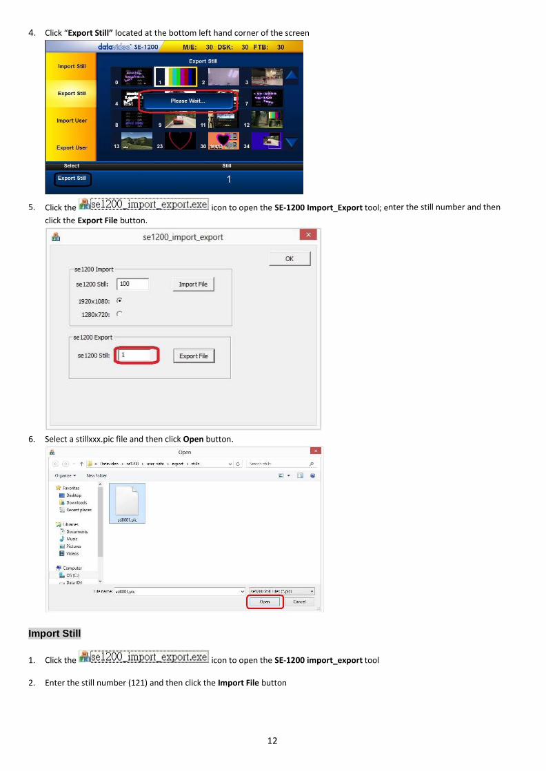
4. Click “Export Still” located at the bottom left hand corner of the screen
5. Click the icon to open the SE-1200 Import_Export tool; enter the still number and then
click the Export File button.
6. Select a stillxxx.pic file and then click Open button.
Import Still
1. Click the icon to open the SE-1200 import_export tool
2. Enter the still number (121) and then click the Import File button

13
3. Select a BMP file and then click Open button
4. Click OK button to save the selected file and exit the import_export tool
14
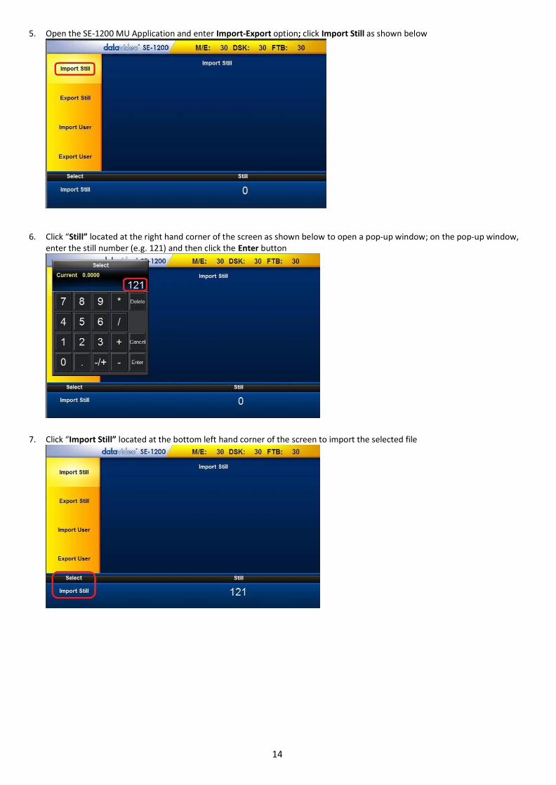
5. Open the SE-1200 MU Application and enter Import-Export option; click Import Still as shown below
6. Click “Still” located at the right hand corner of the screen as shown below to open a pop-up window; on the pop-up window, enter the still number (e.g. 121) and then click the Enter button
7. Click “Import Still” located at the bottom left hand corner of the screen to import the selected file

15
8. Enter “Export Still” to check the thumbnail of the imported still picture file as shown in the diagram below
Export User
1. Click the “Setup” button on the MENU SELECT panel
2. Click “Import-Export” as shown below
3. Click Export User as shown below and use the up/down arrows to browse the saved setups

16
4. Select a Setup and click “Export User” located at the bottom left hand corner of the screen
5. Check the exported files in the directory “C:\Datavideo\se1200\user_data\export\mems”
Import User
1. Copy dvXXX.mem, dvXXX.name and input_namesXXX.mem files from the directory “C:\Datavideo\se1200\user_data\export\mems”

17
2. Paste the three files into the directory “C:\Datavideo\se1200\user_data\import\mems”
3. Click the Setup button on the MENU SELECT panel
4. Click “Import-Export” as shown below

18
5. Click “Import User" as shown below
6. Click “User” (located at the bottom right hand corner of the screen) to open a pop-up window on which the user is allowed to enter an Import User number and then click the Enter button; Click Import User (located at the bottom left hand corner of the screen) to start importing the selected User setup

19
INPUTS Key Functions
Setting Video Inputs
The multiview screens are initially labelled Input 1-6, SDI OUT1 and SDI OUT2 by default. These labels may be changed accordingly
and the label text length is limited to not more than 16 characters.
1. Click the Inputs button on the MENU SELECT panel
2. Select a channel to edit
3. After entering the selected channel, locate and click “Change – Name” at the bottom right hand corner
4. An onscreen keyboard will then be displayed. Enter the desired channel name in the text bar on the onscreen keyboard. Click on the “Back” button to delete. After the new channel name is entered, click on the “Enter” button and the onscreen keyboard should disappear. Your new label should now appear on the Multiview Screen.
20
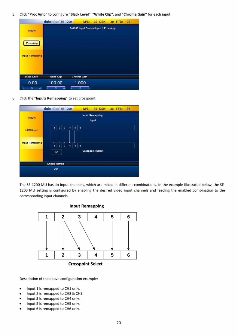
5. Click “Proc Amp” to configure “Black Level”, “White Clip”, and “Chroma Gain” for each input
6. Click the “Inputs Remapping” to set crosspoint
The SE-1200 MU has six input channels, which are mixed in different combinations. In the example illustrated below, the SE-
1200 MU setting is configured by enabling the desired video input channels and feeding the enabled combination to the
corresponding input channels.
Input Remapping
1 2 3 4 5 6
1 2 3 4 5 6
Crosspoint Select
Description of the above configuration example:
Input 1 is remapped to CH1 only.
Input 2 is remapped to CH2 & CH3. Input 3 is remapped to CH4 only.
Input 5 is remapped to CH5 only.
Input 6 is remapped to CH6 only.

21
OUTPUTS Key Functions
Setting Video Outputs
1. To assign the output type to the output, click the Outputs button on the MENU SELECT panel.
2. Assign one of the output types listed below to SDI 1 Out, SDI 2 Out and HDMI Out:
1. Multiview 2. PGM Out 3. PVW Out 4. PGM DSK1 5. PVW DSK1 6. Clean PGM 7. Clean PVW 8. Input 1 9. Input 2 10. Input 3 11. Input 4 12. Input 5 13. Input 6
Setting MultiViewer
This option allows the user to choose the contents of the Main Screen 1 (Main 1 Src) and Main Screen 2 (Main 2 Src). Click Main 1
Src or Main 2 Src to select the source from the list below:
1. PGM Out 2. PVW Out 3. PGM DSK1 4. PVW DSK1 5. P-in-P
Other than the main screen settings, the user can also turn ON/OFF Auto Number (Auto Num), Label Information (Label Info) and
Transparent Labels (Transp Labels).

22
Setting GPI Out
Click GPI Out to configure GPI settings
Click “Enable” to turn ON/OFF GPI Out and configure other GPI-related settings listed below:
Mode: Pulse/Level
Width
Source: Input 1-6
Delay
Setting Streamer
Click “Streamer” to configure the stream settings; the user can set the Stream Size (Full/Half/Quarter/Sixth) in this option. Click
Stream Start to start the stream and click Stream Stop to stop the stream.
Video Streamer Outputs
The SE-1200 MU is capable of streaming the multiviewer over LAN network. Steps to launch a successful video streaming over LAN
network are outlined as follows.

23
1. Click “Stream Start” as depicted below to enable streaming function
2. Please download the VLC media player software (Ver. 2.1.5)
3. Click the icon to start the installation wizard
4. Follow the installation wizards to complete the installation.
5. After the VLC media player is successfully installed, start the program by clicking the icon placed on the desktop. 6. Click “Media” to open a menu

24
7. Select “Open Network Stream…” to open a configuration window
8. Enter the network URL (e.g. tcp://192.168.1.101:5000) in the text bar and set caching time to 50ms ; click the play button

25
AUDIO Key Functions AUDIO option allows the user to configure the Audio Settings of the SE-1200 MU, whereby the user can set the audio mode and
audio source as well as enable/disable audio component of SDI and HDMI output ports.
1. Click the AUDIO button on the MENU SELECT panel
2. The Audio parameters are shown at the bottom of the screen.
3. The “Audio Mode” allows the user to set the audio mode: Off, Digital, Analog or Test.
26
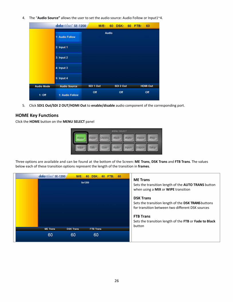
4. The “Audio Source” allows the user to set the audio source: Audio Follow or Input1~4.
5. Click SDI1 Out/SDI 2 OUT/HDMI Out to enable/disable audio component of the corresponding port.
HOME Key Functions Click the HOME button on the MENU SELECT panel
Three options are available and can be found at the bottom of the Screen: ME Trans, DSK Trans and FTB Trans. The values below each of these transition options represent the length of the transition in frames.
ME Trans Sets the transition length of the AUTO TRANS button when using a MIX or WIPE transition
DSK Trans Sets the transition length of the DSK TRANS buttons for transition between two different DSK sources
FTB Trans Sets the transition length of the FTB or Fade to Black button
27
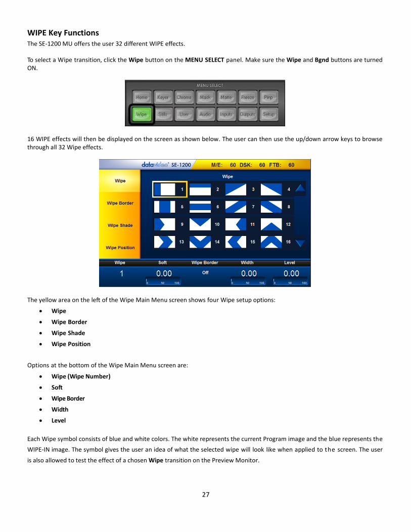
WIPE Key Functions The SE-1200 MU offers the user 32 different WIPE effects.
To select a Wipe transition, click the Wipe button on the MENU SELECT panel. Make sure the Wipe and Bgnd buttons are turned ON.
16 WIPE effects will then be displayed on the screen as shown below. The user can then use the up/down arrow keys to browse through all 32 Wipe effects.
The yellow area on the left of the Wipe Main Menu screen shows four Wipe setup options:
Wipe
Wipe Border
Wipe Shade
Wipe Position
Options at the bottom of the Wipe Main Menu screen are:
Wipe (Wipe Number)
Soft
Wipe Border
Width
Level
Each Wipe symbol consists of blue and white colors. The white represents the current Program image and the blue represents the
WIPE-IN image. The symbol gives the user an idea of what the selected wipe will look like when applied to the screen. The user
is also allowed to test the effect of a chosen Wipe transition on the Preview Monitor.

28
Wipe
To select a WIPE, click Wipe located at the bottom left hand corner and then enter a wipe number using the on-screen keypad.
The current or selected WIPE will be highlighted by a yellow border around it.
Soft Value This value softens the leading and trailing edge (A+C) of the wipe as shown in the diagram below. A low value yields a sharp or
hard wipe edge. A large value yields a softer or diffused wipe edge.
Wipe Border This option enables/disables Wipe Border. Width Value
This value determines how wide the actual wipe effect is. A low value makes a narrow wipe (A and C move closer together).
A large value makes a wider wipe (A and C move further apart). A value of 10 would be the wipe being 10% of the width of the
screen.
Level Value
This value relates to how far the wipe has travelled across the screen and changes as the T-Bar is moved or the AUTO TRANS feature progresses.
Wipe Border
The Wipe Border parameters and the values are currently shown along the bottom of the display below. This feature allows the
user to configure the Wipe Border Matte.
29
Color Palette
The Color Palette allows selection of a color for the Wipe Border Matte. Click on the Color Palette to show the currently selected color which is displayed in the square box with the RGB values calculated on the right. Luma, Sat and Hue values
The color of the Wipe Border Matte can also be configured by adjusting the Luma, Sat and Hue values. These values can be fine-tuned using the Function Dials located just below the Screen.
Source Control
Instead of using a color for the Wipe Border, a video source or a still picture could also be used. As the wipe moves along the screen, the image source is partially revealed across the path of the wipe.
Clicking on “Source” displays a list of 8 options for the Wipe Border source. Use the Up/Down Arrows to scroll through the list and then click on the desired source. Available options are Normal (Single Color Border), Shaded (Dual Color Border), or an Input from 1 to 6.
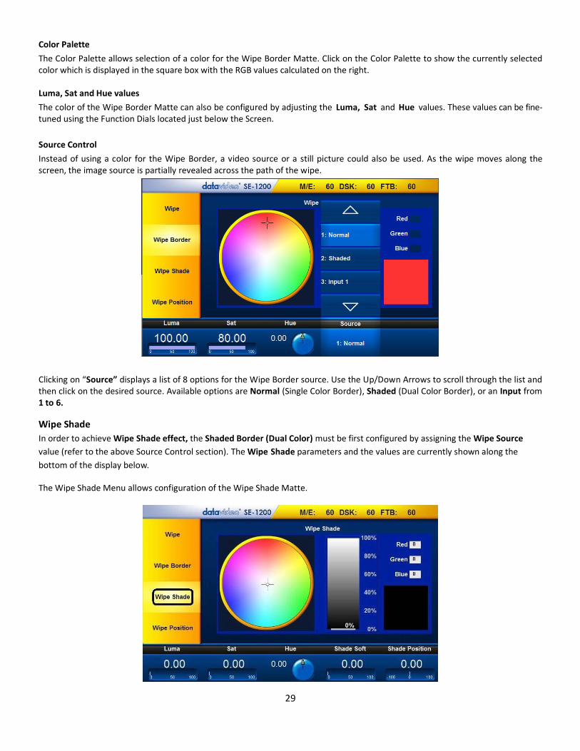
Wipe Shade
In order to achieve Wipe Shade effect, the Shaded Border (Dual Color) must be first configured by assigning the Wipe Source
value (refer to the above Source Control section). The Wipe Shade parameters and the values are currently shown along the
bottom of the display below.
The Wipe Shade Menu allows configuration of the Wipe Shade Matte.

30
Color Palette
The Color Palette allows selection of a color for the Wipe Shade Matte. Click on the Color Palette to show the currently selected color which is displayed in the square box with the RGB values on the right. Hue, Sat and Luma values
The color of the Wipe Shade Matte can also be configured by adjusting the Luma, Sat and Hue values. These values can be fine-tuned using the Function Dials located just below the Screen.
Shade Soft
This blurs or softens the boundary line (B) between the Wipe Shade Matte (area 1) and the Wipe Border Matte (area 2).
Shade Position
The position of the boundary line (B) between the two matte wipe colors (areas 1 and 2) can be adjusted by configuring the Shade Position value.
A positive value moves the boundary line so that the Wipe Shade Matte (area 1) occupies less of the width of the Wipe.
A negative value moves the boundary line so that the Wipe Shade Matte occupies more of the overall Wipe width.
Wipe Position
Position of certain Wipes, such as Circle and Oval, can be adjusted. The Wipe Position parameters and the values are shown along the bottom of the display.
The X value allows the selected wipe to be offset to the left or right of the screen. The Y value allows the selected wipe to be offset to the top or bottom of the screen.

31
STILLS Key Functions The Stills feature allows the user to Grab, Store and Load Uncompressed still pictures on the SE-1200 MU. This feature is
generally used following the use of the Freeze function. It is best to enable Multi Image Preview on the monitor(s) so that you
can see the Program output and any captured still images at the same time. See Multi Image Preview.
To start using the Stills feature, click the Stills button on the MENU SELECT panel
Still Load
The “Still Load” feature allows stills already stored in the SE-1200 MU to be loaded to either one of the Still 1 ~ Still 6 buffers.
Click “Still Load” on the yellow area located on the left of the Stills Main Menu screen. After clicking the “Still Load”, thumbnail
pictures of up to 16 saved stills can be displayed at a time. If there are more than 16 stills stored in the SE-1200 MU, then use
the Up/Down arrows on the right to browse rest of the saved stills. The stills are shown in the numerical order, and unused
numbers will not be shown. The selected still is highlighted with a Yellow border around it.

32
To load a still, the user can simply click on the desired thumbnail picture, or select it by entering the Still number and then click “Load Still” The selected still will then be loaded into the chosen still buffer. In the above example, Input 1 buffer has been loaded with still number 3.
Grab and Save
The Grab & Save feature of the SE-1200 MU allows the user to create new Still Images of the current Program video image and
save the grabbed image to the internal stills buffer of the SE-1200 MU.
Click “Grab Still” to grab Program Output to a Still buffer
View the Multi Image Preview and decide if the grabbed still should be saved
To Save a Still from the Still buffer, the user should select an unused Still number first and then click “Save Still'
The save process takes approximately 4 seconds, after which the new thumbnail picture will be shown in the Stills
display with its corresponding still number.
In addition, the still name or its description can also be added using the “Name” function.
Delete
To delete a saved still, click on the thumbnail picture of the still that is no longer needed and the selected still will be highlighted
with a yellow box around it. Click on “Delete” located at the bottom of the screen to remove the selected still from the SE-1200
MU memory.

33
KEYER Key Functions
Keyer Control
Lift: configures dark/black areas in the key
image/source feed. Gain: configures light/white areas in the key
image/source feed. Opacity: configures how transparent the overall
foreground key image/source is.
Invert: reverses the effect the current Luma Key
settings. Hence, if you can currently see the background video through the dark areas of the key image/source feed, then enabling Invert would make the background video seen through only the light/white areas instead.
Keyer Matte
1. Locate Color Palette which allows selection of a color for the Keyer Matte.

34
2. Click on the Color Palette and the crosshair to display the currently selected color with its RGB values shown on the right. 3. The Luma value determines how bright or dark the selected color or hue is. The Luma value can be adjusted by the
Luma Function keypad. 4. The Sat or Saturation value moves the crosshair from the center of the color palette to the outer edge. The Sat value can
be adjusted using the Sat Function Keypad. If the Hue angle is set to 180 degrees then the Sat value determines how much Cyan is in the matte.
5. The Hue parameter moves the crosshair around the color palette in the clockwise or anti-clockwise direction. The Hue value/angle can be adjusted using the Hue Function dial.
6. Certain color hues can be found at certain angles on the color palette. For instance, Red is 0 degrees (12 o’clock position), Green is approximately 120 degrees (4 o’clock position) and Blue is approximately 240 degrees (8 o’clock position).
7. Once the correct keyer has been chosen and set up correctly, the Matte function can then be switched on by clicking the MATTE button on the KEYER CONTROLS panel.
Luma Key Quick Set Up
In this example, we will be supplying the SE-1200 MU with an HD-SDI background feed on input 2; click button with the STILL
source on the Aux Bus row and this will be used for Luma keying a static white shape over the video from input 3. We have
already assigned a still with a black/dark background and white or light colored text to the STILL1 buffer.
Step 1: Choose the Keyer channel that you want to use. In our example, we will click the Key 2 button on the AUX BUSES panel.
Step 2: Choose the type of Keyer you want to use. In our example, we will click the Luma button on the KEYER CONTROLS panel.
Step 3: Select the foreground video source to be keyed. In our example, we want to use the STILL 1 source to overlay some text. Hence, click STILL 1 source on the Aux Bus Row so it is backlit Green. We have also chosen button 2 on the Program row as our background video.
Step 4: Turn the keying effect on. Click the On button so it is backlit green. In our example, you will now see the selected source button on the Aux Bus Row change to backlit Red.
Step 5: Make some adjustments to the Luma key. Click the Keyer button on the MENU SELECT panel and the menu screen will appear as depicted in the diagram on the left. The options along the bottom of the Screen will now allow you to calibrate for a white or black key using the Lift, Gain, Opacity and Invert Function Dials or the Screen. Keyer Control section will explain the effects of Lift, Gain, Opacity and Invert.

35
DSK1 and DSK2 Quick Setup
DSK1 and DSK2 can be used for Linear or Luma keying only. Chroma Keying is not supported on DSK1 and DSK2.
For this example, we will be supplying the SE-1200 MU with a background feed on button 5. Select a CG-350 overlay input using button 4 on the Aux Bus row.
Step 1: Choose the Keyer channel that you want to use. In our example, click the DSK 1 button on the AUX BUSES panel.
Step 2: Choose the type of Keyer you want to use.
Step 3: In our example, click the Lin button on the KEYER CONTROLS panel. Note: If DSK only has one source for key source, press Self button If DSK has two sources for Fill source & Key source, press Split button. Step 4: Click Split button (backlit green), select key source on AUX BUS Row. Step 5: Click Split button again (backlit orange), select Fill source on AUX BUS Row.
Step 6: Turn the keying effect on. Click the On button so it is backlit green.
In our example, you will now see the selected source button 4, on the Aux Bus Row, change so it is now backlit Red.
Step 7: Make some adjustments to the Luma key. Click the Keyer button on the MENU SELECT panel to open the Screen Menu as shown on the left. Lift: LUMA Key lightness, please set 0. Gain: LUMA Key darkness, please set 1 Opacity: LUMA Key transparency, please set 100 Invert: LUMA Key invert, please set Off

36
SE-1200 MU Keying layers
The SE-1200 MU has 4 dedicated keyers, Key1, Key2, DSK1 and DSK2. All four keyers can be active simultaneously. Key 1 & Key 2 are M/E keyers which can be set Upstream or Downstream of the M/E Wipe/Mix Transition using the Transition Controls. DSK 1 & DSK 2 are always Downstream of the M/E Transition. The Layer priority of Key 1 & Key 2 can also be set by the user using the Priority Transition Button, and the Top button on the Keyer controls section. See diagram below for an example of keyer layering.
For details on how the order of Key1 & Key2 can be changed, please refer to the Priority button section.

37
CHROMA Key Functions
Overview
The Chroma Key feature of the SE-1200 MU is easy to use. Typical Blue and Green screen studios can be quickly incorporated into
an SE-1200 MU production.
First of all, we will go over some basics, and then we will describe the Control Panel buttons and finally a simple green backdrop
setup for illustration purpose. For those of you who need a quick review, the following are a few Chroma Key basics.
A good foreground image helps generating a good key The camera, backdrop and lighting all play an important role in producing the optimal Chroma Key result. Although the SE-1200
MU is equipped with excellent keying controls, it is still always best to start with an optimal keyable image.
Three Chip Camera We strongly recommend the use of a three chip (or CCD) camera for Chroma Key shooting. The extra image clarity and the good
color separation that a three chip camera produces really do improve the quality of the subsequent keying.
White Balance the Camera White Balance is extremely important when setting up a chroma key studio. The camera must be correctly white balanced to
minimize the subject picking up any color cast from the background. Of course the white balance settings will vary
according to the type of lighting you are using, but neutral whites and good skin tone color are the all-important targets.
To set the white balance you will need a white reference card (or a sheet of white paper). Focus the camera on the reference card
and light it evenly using the main light. Set the camera’s iris / aperture so that the card is correctly exposed. Use the Auto White
Balance (AWB) function, or set the white balance manually so that the card appears white. If you are in any doubt about how to
white balance your camera, please refer to your Camera’s instruction manual for more details.
38
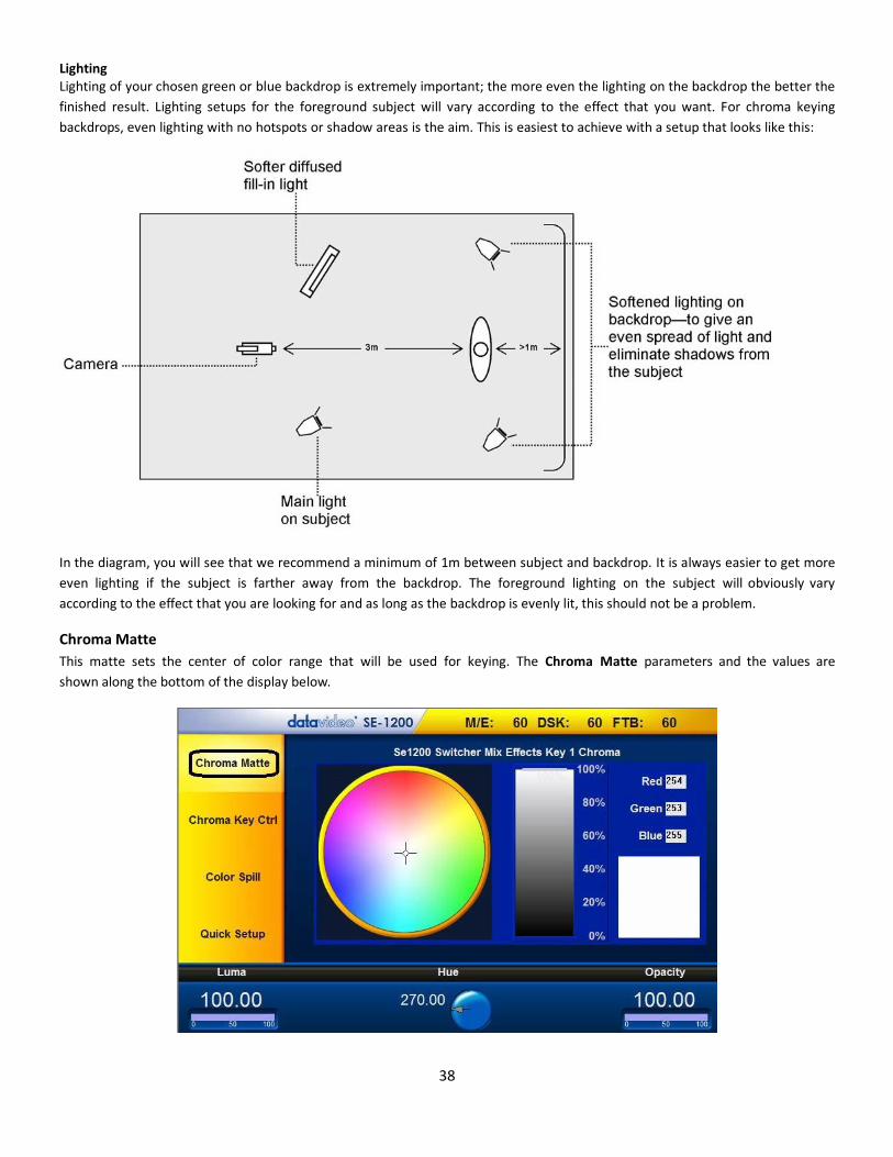
Lighting Lighting of your chosen green or blue backdrop is extremely important; the more even the lighting on the backdrop the better the
finished result. Lighting setups for the foreground subject will vary according to the effect that you want. For chroma keying
backdrops, even lighting with no hotspots or shadow areas is the aim. This is easiest to achieve with a setup that looks like this:
In the diagram, you will see that we recommend a minimum of 1m between subject and backdrop. It is always easier to get more
even lighting if the subject is farther away from the backdrop. The foreground lighting on the subject will obviously vary
according to the effect that you are looking for and as long as the backdrop is evenly lit, this should not be a problem.
Chroma Matte
This matte sets the center of color range that will be used for keying. The Chroma Matte parameters and the values are
shown along the bottom of the display below.

39
The Hue can be configured by moving the crosshair around the color palette in the clockwise or anti-clockwise direction. The Hue value can be adjusted by using the Hue Function dial. Certain color hues can be found at certain angles on the color palette. For instance, Red is 0 degrees (12 o’clock position), Green is approx. 120 degrees (4 o’clock position) and Blue is approx. 240 degrees (8 o’clock position). Secondary colors are Yellow at 60 degrees, Cyan at 180 degrees and Violet at 300 degrees. The Luma value relates to how bright or dark the selected color or hue is. The Luma value can be adjusted using the Luma Function dial. The Opacity setting affects how transparent the overall foreground key image/source is. Increasing the value of Opacity makes the overall key image less transparent.
Chroma Key Ctrl
The Chroma Key Ctrl parameters and the values are shown along the bottom of the display below. Two color palettes, Main and
Chroma, are shown in the diagram below. The Main palette corresponds to values of Key Acceptance and Key Lift. The Chroma
palette corresponds to the Color Spill settings.
Key Acceptance is represented on the Main Palette as a sector or area covering a range of hues or colors that closely match the background color to be keyed as set in Chroma Matte. The user can start with a value of 120 degrees and this value can be fine-tuned up or down using the Key Acceptance depending on the setup of the green or blue screen studio. Key Lift is represented on the Main Palette as a line extending from the center point in the direction of the Key Acceptance sector. This value affects the performance of the Chroma key in dark or black areas. If the dark areas of the video are becoming too transparent, then applying more Key Lift may help depending on the setup of the green or blue screen studio. This value can be fine-tuned up or down using the Key Lift Function Dial. Key Gain affects the performance of the Chroma key in light or white areas. If the light areas of the video are becoming too transparent then applying more Key Gain may help depending on the setup of the green or blue screen studio. This value can be fine-tuned up or down using the Key Gain Function Dial.
Color Spill
The Color Spill parameters and the values are shown along the bottom of the display below. These settings are used to
control/remove any unwanted Chroma Spill from the background onto the foreground. There are two sectors drawn on the
Chroma palette, one represents the wider Chroma Acceptance range and the other a narrower Chroma Suppress range.

40
Chroma Acceptance sets the amount of the available color range or space that should be Chroma suppressed. Usually starting
with a large value of 120 degrees should produce reasonable results. This value can then be fine-tuned up or down using the
Chroma Acceptance Function Dial depending on the setup of your green or blue screen studio.
Chroma Suppress, when set to 0%, removes the hues or colors that lie only on the same axis as the Chroma Matte Hue angle. This
setting has the effect of removing Background color spill, but keeping the underlying hue. When set to 100% then all the Chroma
values that are ‘captured’ within the Chroma Acceptance Angle are suppressed to mono – i.e. they have their Chroma removed.
Usually starting with a value of 50% should produce reasonable results. This value can then be fine-tuned up or down using the
Chroma Suppress Function Dial depending on the setup of your green or blue screen studio.
The Bgnd Suppress Control is used to remove the Luma (brightness) of the background from the final image. If the Chroma Key
Output is showing Light Edges, then the Bgnd suppress can be used to suppress any background Luma that is showing
through on these edges.
Saving the Chroma Key Setup
Once you are done with the Chroma Key setup, remember to save your current user setup. In this way, several Chroma Key
setups are saved to different user memory slots, thus allowing you to switch from a Blue screen setup to a Green screen setup
instantly.
Chroma Key Quick Setup
Step 1: Choose the desired Keyer channel. In our example, click Key 1 button on the AUX BUSES panel.
Step 2: Choose the type of Keyer you want to use. In our example, click Chroma button on the KEYER CONTROLS panel.

41
Step 3: Select the foreground video source to be keyed. In our example, we want to use the green screen source connected to Input 5, so click button 5 of the Aux Bus Row such that it is backlit Green.
Step 4: To turn the keying effect on, click On button so that it is backlit green. In our example, you will now see the selected source button 5 on the Aux Bus Row changes so that it is now backlit Red.
Step 5: Make some initial adjustments to the key. Click Chroma button on the MENU SELECT panel. Choose Quick Setup on the Yellow menu bar located on the left of the Screen. The parameters along the bottom of the Screen will now allow you to quickly calibrate for a basic green or blue key. You can then move on to fine tune the key using Chroma Key Ctrl and Color Spill options.

42
MASK Key Functions The Mask feature allows the user to configure the Mask on the SE-1200 MU in either Chroma mode or Luma mode.
1. Click the MASK button on the MENU SELECT panel
2. Make sure the correct Keyer is enabled (backlit Green) on the Aux Buses panel
3. Once the correct keyer has been chosen, the Mask function can then be enabled by clicking the MASK button on the
KEYER CONTROLS panel.
4. The Mask parameters are displayed along the bottom of the screen.
5. The Left, Right, Top & Bottom Function dials allow the user to set the Left, Right, Top & Bottom edges of the keyer mask.
Note: These mask edges are fully transparent during the keying process. This is helpful if the blue or green backdrop does not
occupy the whole foreground shot. It is also helpful if only a small area of the foreground image is being Luma keyed. Each value is
based on a percentage of the screen width or height, thus 0% indicates no mask edge and 50% means masking half of the screen
area.

43
MATTE Key Functions Matte option allows the user to configure the matte. The configuration steps are described below:
1. Click the Matte button on the MENU SELECT panel
2. The Bus Matte parameters are shown at the bottom of the screen.
3. Locate Color Palette which allows selection of a color for the Bus Matte.
4. Click on the Color Palette and the crosshair to display the currently selected color with its RGB values shown on the right.
5. The Luma value determines how bright or dark the selected color or hue is. The Luma value can be adjusted by the Luma Function keypad.
6. The Sat or Saturation value moves the crosshair from the center of the color palette to the outer edge. The Sat value can
be adjusted using the Sat Function Keypad. If the Hue angle is set to 180 degrees then the Sat value determines how much Cyan is in the matte.
7. The Hue parameter moves the crosshair around the color palette in the clockwise or anti-clockwise direction. The Hue
value/angle can be adjusted using the Hue Function dial.
8. Certain color hues can be found at certain angles on the color palette. For instance, Red is 0 degrees (12 o’clock position), Green is approximately 120 degrees (4 o’clock position) and Blue is approximately 240 degrees (8 o’clock position).
44
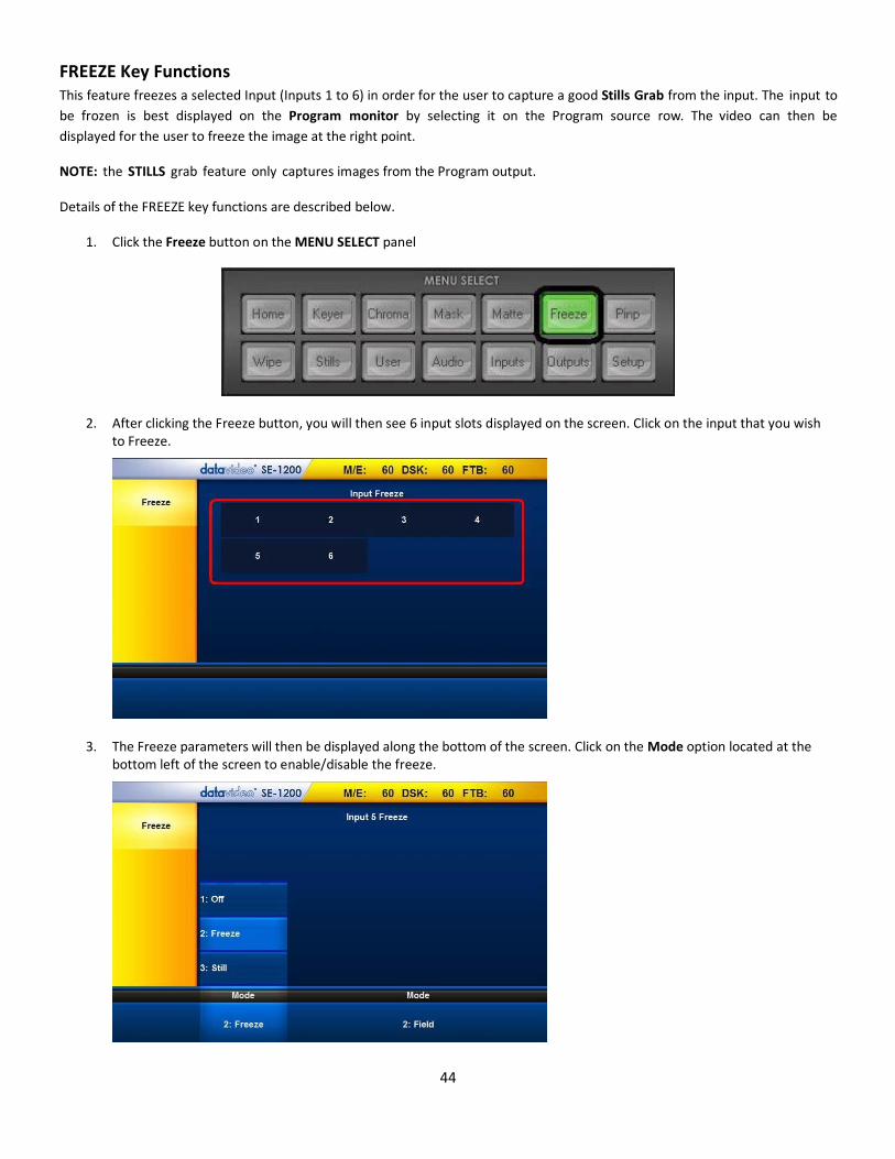
FREEZE Key Functions This feature freezes a selected Input (Inputs 1 to 6) in order for the user to capture a good Stills Grab from the input. The input to
be frozen is best displayed on the Program monitor by selecting it on the Program source row. The video can then be
displayed for the user to freeze the image at the right point.
NOTE: the STILLS grab feature only captures images from the Program output.
Details of the FREEZE key functions are described below.
1. Click the Freeze button on the MENU SELECT panel
2. After clicking the Freeze button, you will then see 6 input slots displayed on the screen. Click on the input that you wish to Freeze.
3. The Freeze parameters will then be displayed along the bottom of the screen. Click on the Mode option located at the bottom left of the screen to enable/disable the freeze.

45
4. The Freeze Mode located at the bottom right of the screen can be set to a full frame or one field.
Note: Remember to turn the Freeze function off after you have finished using it.
Freeze – Still
Please refer to the example below if you would like to set the input channel source to the still picture.
1. Click the Stills button on the MENU SELECT panel.
2. Click “Still Load”, and then select Input 1 for the Still Buf and enter 0 for the Still as shown in the diagram below
3. Click the Freeze button on the MENU SELECT panel

46
4. After clicking the Freeze button, you will then see 6 input slots displayed on the screen; click on Input 1
5. The Freeze options are shown along the bottom of the screen.
6. Select the Still and Frame for the respective modes

47
P IN P Key Functions The user-defined output allows a choice of background image/video plus two optional PiPs which can be sized, rotated, positioned
and cropped. The PiP window can also have user-defined colored borders too. Configuration steps are described below.
Step 1: Choose the desired Keyer channel. In our example, Key 2 button on the AUX BUSES panel is clicked.
Step 2: Click PinP button to enable PiP function (backlit green); user is allowed to define the PiP source on the AUX BUS row of the SOURCES panel.
Step 3: Turn the keying effect on by clicking the On button (backlit green)
Step 4: PiP parameters are displayed in the yellow menu area: Position, Crop, Border and Size.
PIP Position
The Position parameters and the values are shown along the bottom of the screen.
The X and Y values change the location of the PiP image. The X value moves the image left and right. The Y value moves the image
up and down. The Z value adjusts the PiP image size.
48
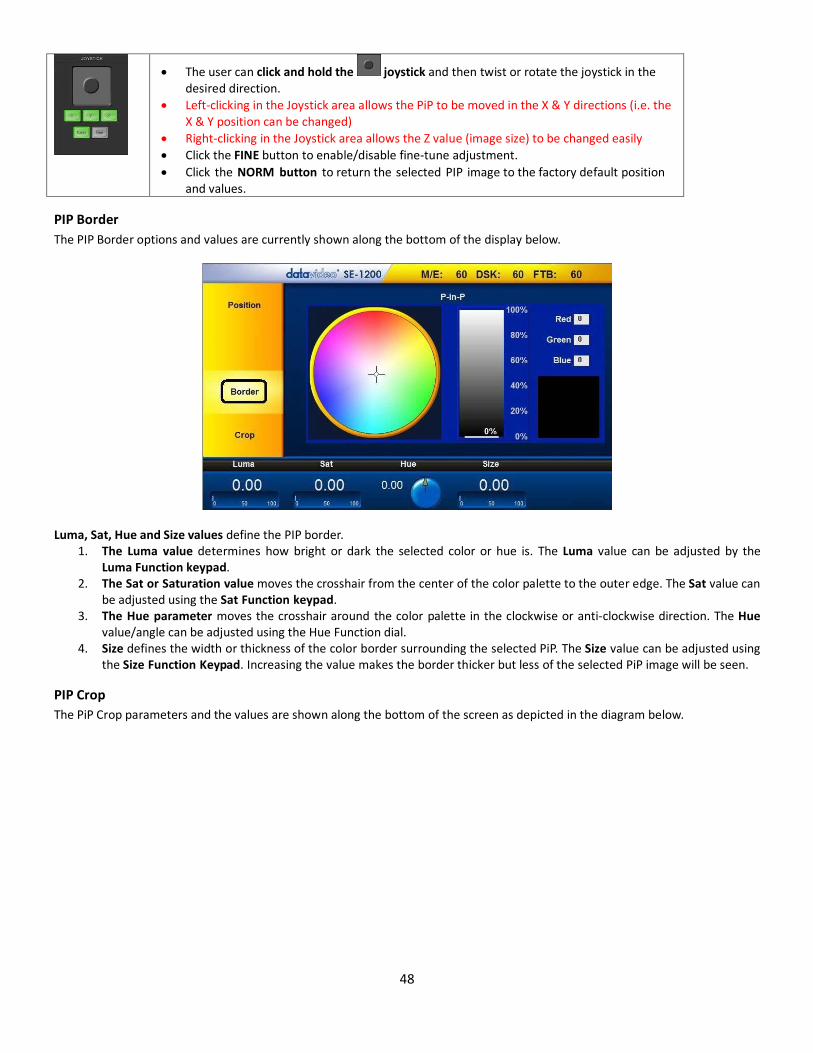
The user can click and hold the joystick and then twist or rotate the joystick in the desired direction.
Left-clicking in the Joystick area allows the PiP to be moved in the X & Y directions (i.e. the X & Y position can be changed)
Right-clicking in the Joystick area allows the Z value (image size) to be changed easily
Click the FINE button to enable/disable fine-tune adjustment.
Click the NORM button to return the selected PIP image to the factory default position and values.
PIP Border
The PIP Border options and values are currently shown along the bottom of the display below.
Luma, Sat, Hue and Size values define the PIP border. 1. The Luma value determines how bright or dark the selected color or hue is. The Luma value can be adjusted by the
Luma Function keypad. 2. The Sat or Saturation value moves the crosshair from the center of the color palette to the outer edge. The Sat value can
be adjusted using the Sat Function keypad. 3. The Hue parameter moves the crosshair around the color palette in the clockwise or anti-clockwise direction. The Hue
value/angle can be adjusted using the Hue Function dial. 4. Size defines the width or thickness of the color border surrounding the selected PiP. The Size value can be adjusted using
the Size Function Keypad. Increasing the value makes the border thicker but less of the selected PiP image will be seen.
PIP Crop
The PiP Crop parameters and the values are shown along the bottom of the screen as depicted in the diagram below.

49
Left, Right, Top and Bottom edge values of the crop can be adjusted using the Left, Right, Top and Bottom Function Keypad. The Size value evenly crops all edges of the selected PIP at the same time. Sets this value using the Size Function Keypad.
USER Key Functions The USER menu button allows you to Store and Recall User Setups on the SE-1200 MU. If you have standard configurations for
your productions then this feature can save you a lot of time by not having to re-configure the SE-1200 MU after someone else
has used it. The SE-1200 MU allows the user to store up to 1000 User Setups, numbered from 0 – 999.
Storing an user setup to a user memory slot
Steps to storing an user setup to a user memory slot are outlined as follows:
1. Click the USER button on the MENU SELECT panel
2. Click “Save Memory” and the screen below will appear; customize your setup first
3. Click “User Memory” to set the user memory slot to which the user setup is saved
4. Click “Name” to label the user memory slot

50
5. Click “Save Memory” to store the setup to the assigned user memory slot
Labelling an existing User memory slot
In order to allow the user to easily identify the stored setup, the user memory slot can be labelled for future reference. The
following outline the steps to label the user memory slot.
1. Click the USER button on the MENU SELECT panel
2. The Screen Menu will then appear as shown below.
3. The screen displays up to 16 user memory slots at a time. Click on a user memory slot and the selected user slot will have a
yellow border.
4. Click “Name” at the right hand corner of the bottom of the screen to open an on-screen keyboard and then type a label
name for the selected user memory slot. The label name can be up to 16 characters long but only the first 10 letters will
be displayed on the User Memories screen.
Note: If there are more than 16 User Setups stored in the SE-1200 MU, then use the up/down arrows to browse through all user
memory slots. The user memory slots are displayed in numerical order, and unused numbers will not be shown.
Loading a previously saved User Setup
There are two ways to load a previously saved user setup. The two methods are described as follows:
1. USER/SHOT BOX Panel

51
To load a previously saved SE-1200 MU Setup, simply click the LOAD button on the USER/SHOT BOX panel and an on-screen number pad will open.
Enter the number of the required setup and then click ENTER
Note: If the user were to save the user setup to one of the first 8 memory slots, then simply click the corresponding button on the USER / SHOT BOX panel.
2. “Load Memory” feature in the “User” option on the “MENU SELECT” panel
Another way to load a saved Setup is to enter the “USER” option on the “MENU SELECT” panel.
The screen displays up to 16 user memory slots at a time. Click on a user memory slot and the selected user slot will have a
yellow border. User 0 is the default preset, which is loaded after the SE-1200 MU is booted and can also be used to set the
start-up configuration of the SE-1200 MU.
At the left hand corner of the bottom of the screen, click “Load Memory” to load the selected user memory slot.

52
Deleting a User Setup
The user is allowed to delete saved user setups. Below are steps to deleting a user setup.
1. Click “Delete Memory” on the yellow menu bar located on the left of the screen
2. To delete an existing User-defined Setup from a particular User Memory slot, click on a user memory slot on the “Delete Memory” screen.
3. Confirm deletion of the selected User Memory Slot by clicking “Delete Memory” located at the bottom of the screen.

53
Sources Panel This panel consists of three identical rows of buttons and is used to assign sources or select images for Program or Preset outputs. The buttons are labelled from left to right as Black, sources 1 to 6, and Matte. The way these buttons operate follows industry standard conventions.
AUX BUS This row of buttons is typically used to assign sources in the presence of an Auxiliary Monitor, as well as for setup of the Linear, Chroma and Luma Keyer functions.
PROGRAM This row of buttons is typically used to select sources or images for the SE-1200 MU main Program output. The currently selected
source is being sent to the Program output will be backlit Red. Simple cuts between sources can be performed on this row by
clicking on the source number required for the next shot.
PRESET This row of buttons is typically used to select sources or images for the SE-1200 MU Preview output. The currently selected source
will be backlit Green. The selected button on the Preset row will change from Green to Yellow during Preview-Program
transitioning using T-Bar.

54
Transition The Transition Control controls what the “next” transition (mix, wipe, cut, using Auto or the T-bar) will do, i.e. they specify what is
“in the transition.”
Transition Panel The Transition panel allows the user to bring the selected Preset source to the Program output. The SE-1200 MU user may
determine to use either one of the Mix, WIPE, Cut and AUTO transitions. In order to use these transition options, the BGND
(Background) button on the TRANSITION CONTROLS panel needs to be enabled (backlit green).
Transition Modes
Mix Button The Mix button is selected when a dissolve or fade transition between the selected Program and a Preset source is required. This Mix transition is generated by moving the T-Bar manually or clicking the Auto button. Wipe Button The Wipe button is selected when a wipe effect transition between the selected Program and a Preset source is required. This WIPE effect is generated by moving the T-Bar manually or by clicking the Auto button. Cut Button The Cut button is used to instantaneously switch between the currently selected Program and a Preset source. Auto Button Instead of using the manually operated T-Bar, the Auto button is used to automatically transition between the selected Program and a Preset source over a set period.
Previewing a selected transition
It is possible to see or test the effect of a selected transition in the Preview Monitor before applying it to the Program output.
Once the Pvw button (TRANSITION CONTROLS panel) is ON (backlit Green), select and apply the transition that you want to test on the Preview monitor. You will also notice that the Preview Monitor switches to the currently selected Program source when the Pvw button (TRANSITION CONTROLS panel) is turned on. Do not worry as the selected Preset source has not changed. Click the Auto button (TRANSITION panel) or move the T-Bar manually to preview the selected transition. NOTE: Remember to disable the Pvw button (TRANSITION CONTROLS panel) before attempting to use the selected transition on the Program output.

55
Transition Controls Panel
Key 1 and Key 2
Key 1 and Key 2 specify that Keyer 1 or 2 will be transition ON or OFF (i.e. if it's currently on, then it will be off after the
transition, and vice versa)
Each KEY button has an LED above it. This LED can be Red or Green. The KEY button itself can be Off or On (back lit Green when
On). To understand the relationship between the KEY button and the LED above, try the following example with Key1 already
set up as described under the previous Keying sections (Previewing a selection transition).
1. If the KEY1 button is Off and the LED above it is Red, then KEY1 is not active in Program or Preview. 2. If the KEY1 button is On and the LED above it is Red, then KEY1 is currently active in Preview Only. 3. If a CUT, MIX, WIPE transition is performed with the T-Bar or AUTO TRANS button then KEY1 will move to the Program
output. Once the transition is complete, the LED above KEY1 will change from Red to Green to confirm the key is
currently active on the Program output.
4. If the T-Bar or AUTO TRANS button is used again, then the KEY1 button will remain On but the LED above will change back
from Green to Red. KEY1 is now removed from the Program output and is active only in the Preview output.
5. To remove KEY1 from the Preview output, press the KEY1 button so it is off and not back lit Green. The LED above
KEY1 should be Red also. This confirms KEY1 is not active in Program or Preview and we are now back at point 1.
The Key2 button and the LED above it perform in exactly the same way as described for Key1.
Once Key1 and Key2 are properly set up, they can both be used separately within the same production or placed over one another
so they are both displayed within the Preview / Program output.
Before using the two keys at the same time in a live production, some preparations are required. The best way is to keep the keys
simple. The user should decide which key should be on top and practice the effect that you want to create a few days before
the live event.
The SE-1200 MU has several buttons for deciding the on-screen order of the Key1/Key2 as well as deciding how the key will enter
or exit, from the production. In the following example, we will be using buttons on the Transition Controls and Transitions panels
whilst looking at the Preview and Program monitors.
BGND – Background
BGND specifies that the Background will be “transitioned” from the Program source to the Preset Source.

56
When on (back lit Green), this button includes the background image/video in any chosen transition from Preview to Program.
When this button is toggled, or switched off, any Keyer transition chosen will not change the background Program image/video.
PRIORITY Key Function
PRIORITY specifies that the Layer Priority of Keyer 1 & Keyer 2 will be swapped.
When Key1 and Key2 are both active in Preview (or Program), they may overlap each other on the screen. Using the Priority
Button you can change the order of these keyers. The button acts in a toggle on/off way, i.e. Key1 over Key2 or Key2 over
Key1.
NOTE: It is best to check and change the Priority of Key1 and Key2 when they are only active on the Preview
monitor/output.
Rev and Nrm (NORM) / Rv (REV) buttons
When the Rev and Nrm / Rv buttons are OFF, the selected WIPE transition will operate in its default direction only. When the Rev
button is ON then the selected transition will operate in the reverse direction only.
When the Nrm / Rv button is ON, the selected WIPE transition will automatically switch directions as each transition is completed.
The Rev button will switch on and off automatically to indicate the direction of the next transition.
DSK TRANS Panel
Each DSK button has an LED above it. This LED can be Red or Green. The DSK1 or DSK2 button itself can be off or on (back lit Green when on). To understand the relationship between the DSK button and the LED above, try the following example with DSK1 already set up as described in the section outlining DSK1 and DSK2 Quick Setup.
1. If the DSK1 button is off and the LED above it is Red then DSK1 is not active in Program or Preview.
2. If the DSK1 button is on and the LED above it is Red then DSK1 is currently active in Preview Only.
3. If the CUT or AUTO TRANS button is pressed then DSK1 will move to the Program output. Once the transition is complete the
LED above DSK1 will change from Red to Green to confirm the DSK is currently active on the Program output. NOTE: The T-Bar has
no effect on DSK transitions.
4. If the CUT or AUTO TRANS button is used again then the DSK1 button will remain on but the LED above will change back from
Green to Red. DSK1 is now removed from the Program output and is active only in the Preview output.
5. To remove DSK1 from the Preview output, press the DSK1 button so it is off and not back lit Green. The LED above KEY1 should
be Red also. This confirms DSK1 is not active in Program or Preview and we are now backing at point 1.
The DSK2 button and the LED above it perform in exactly the same way as described above.

57
FTB Key Function
Enable
Enable the Fade to Black function.
FTB
Fade to Black, this button fades the current video program source to black. When clicked again it acts in reverse from complete
black to the currently selected program video source.
Keyer Controls Panel
Matte Key Function
When Matte is selected on the KEYER CONTROLS panel, the current active Key is filled with a Matte color rather than video. The
Keyer Matte option allows selection of this Matte color.
Lin Key Function The Lin or Linear button sets up the keyer so it uses the luminance signals of the selected Key Source.
Top Key Function The SE-1200 MU is able to show Key1 over Key2 or Key2 over Key1 if they are both ON or active. Use the Top button to decide
which Keyer will have Priority.
Self Key Function This mode only applies to Luma Key Mode. The same source is used for both the Key signal and the Fill signal for the Luma Key.
Split Key Function
This mode can be used with both the Luma Key Mode, and the Linear Key Mode. It allows the user to specify different
sources for the Key signal and the Fill Signal.
Button is green: the Aux Bus can be used to select the Key signal
Button is yellow: the Aux Bus can be used to select the Fill signal

58
Luma Key Function
The mode can be used with either Self key mode or Split mode.
In this mode, the Key signal is taken from the Luma value of the selected Key source.
Lift & Gain is applied to this Key signal to obtain the desired Key.
'S' shaped Key shaping is applied to this Key signal to remove any hard edges that would otherwise be apparent from the Key signal.
This key signal is then used to Key the foreground Key video and create the opposite key hole in the background.
Linear Key Function
This mode should only be used with the Split Key Mode.
In this mode, it is assumed that the Key signal is coming from a device such as a CG.
The video signal will have been pre-keyed by the CG (i.e. generated over a black background), so the
foreground is not re-keyed in this mode (otherwise double keying of the foreground video would occur).
The SE1200MU still allows Lift & Gain to be applied in case there needs to be some minor adjustment of the
key signal (however, normally this should not be necessary if the CG has correctly generated the key).
Since the Key signal is assumed to be correct for this Video & Key combination, 'S'-shaped key shaping is not
applied in this mode.

59
Specifications Datavideo SE-1200 MU HD Switcher
Connections
Total Video Inputs 2 (HDMI ver1.3) + 4 SDI
Total Outputs 2 HDMI+ 2 SDI
SDI Video Input 4 ( 1080i / 720p )
Analog Video Input N/A
HDMI Video Input 2 x HDMI (RGB/YUV)
1080i / 1080p / 720p
Analog Audio Output N/A
SDI Audio Output (PGM output) 2CH
Analog Audio Input 2CH XLR
Sync Input N/A
PGM Out HDMI / SDI
Multiview Out
HDMI
In 720P mode ; MV output by HDMI is 720P
In 1080i mode ; MV output by HDMI is 1080P
Output can select any of input source
PROGRAM (w/ DSK 1 & 2)
PROGRAM (w/ DSK1)
Clean PROGRAM
PREVIEW (w/o DSK)
MULTISCREEN
Input 1~6
Audio Indicator on Multiview Y ( output 2CH)
Down Converted SDI Program Output N/A
Down Converted Composite Program Output N/A
Computer Output Ethernet (Motion JPEG Out)
60
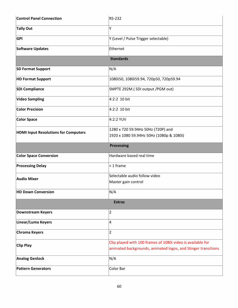
Control Panel Connection RS-232
Tally Out Y
GPI Y (Level / Pulse Trigger selectable)
Software Updates Ethernet
Standards
SD Format Support N/A
HD Format Support 1080i50, 1080i59.94, 720p50, 720p59.94
SDI Compliance SMPTE 292M.( SDI output /PGM out)
Video Sampling 4:2:2 10 bit
Color Precision 4:2:2 10 bit
Color Space 4:2:2 YUV
HDMI Input Resolutions for Computers 1280 x 720 59.94Hz 50Hz (720P) and
1920 x 1080 59.94Hz 50Hz (1080p & 1080i)
Processing
Color Space Conversion Hardware based real time
Processing Delay < 1 frame
Audio Mixer Selectable audio follow video
Master gain control
HD Down Conversion N/A
Extras
Downstream Keyers 2
Linear/Luma Keyers 4
Chroma Keyers 2
Clip Play Clip played with 100 frames of 1080i video is available for
animated backgrounds, animated logos, and Stinger transitions
Analog Genlock N/A
Pattern Generators Color Bar

61
Transition Keyer (Stinger/DVE) Available
DVE with 3D Borders & Drop Shadow N/A
PIP 1
XPT Y
Frame store 24
Control Panel Compatibility Use PC ; Control panel (optional) by RS-232 / Ethernet
Input Voltage 8V~17V
Power Consumption 12V/19W
Audio Delay N/A
Logo
Any Input (1-6) can be used to provide a Logo (with Key) or an
Animated Logo (with Key) from Clip/Animation store.
Any keyer (Key1, 2, DSK1, 2) can be used to Key in the Logo or
Animated Logo.
Control Protocol DVIP
Multiview Monitoring
Number of Windows 2+6 (+2 Output windows currently)
Routable Windows Y (Follow XPT)
Tally Y
Windows Source Labels Y

62
Note

63
Note