Embed Size (px)
Citation preview

TECHNICAL GUIDE
SPLIT-SYSTEMHEAT PUMPS
EA090/FA090
208/230/460VOLT ONLY
036-21371-001-B-0203
FOR DISTRIBUTION USE ONLY - NOT TO BE USED AT POINT OF RETAIL SALE
� �DESCRIPTION
YORK has combined the latest concepts in modern technology withtime-proven quality standards to design a split-system heat pump tomeet the demands of the energy-and quality-conscious commercialmarket.
Both the outdoor and indoor units are completely piped and wired atthe factory. Only the interconnecting liquid and vapor lines are requiredto complete the refrigerant circuit. Every unit is dehydrated, evacuated,leak tested and pressure tested before being pressurized with a hold-ing charge of refrigerant-22 for shipment and/or storage. The compres-sor, the fan motors and the controls are functionally tested after theunits are fabricated to assure a reliable start-up and years of depend-able operation.
These units have been tested by Underwriters' Laboratories and willbe shipped with UL and CUL labels.
OUTDOOR UNIT
Every outdoor unit includes a heavy-duty compressor with a crankcaseheater, line break overload protection, a suction line accumulator witha fusible plug, a 4-way reversing valve with a 24-volt solenoid, outdoorfan motor(s) with inherent protection, and a copper tube/aluminum fincoil that is positioned vertically for better drainage of the water that willcondense on it during the heating cycle.
They also include a filter-drier, an expansion valve and a distributorthat are only used during the heating cycle plus a check valve to pro-vide the proper flow of refrigerant through the unit during both the cool-ing and heating cycles.
To eliminate the costly cabinet deterioration problems usually associ-ated with outdoor equipment, all sheet metal parts are constructed ofcommercial grade (G90) galvanized steel. After fabrication, each partis thoroughly cleaned to remove any grease or dirt from its surfaces.The parts that will be exposed to the weather are then coated with a“desert sand” powder paint to assure a quality finish for many years.This coating system has passed the 750 hour, salt spray test perASTM Standard B117. To assist in servicing, the high and low pressureservice connections are exterior to the cabinet, allowing simpleaccess.
The fan guards are vinyl-coated to provide additional rust protection.An optional decorative coil guard is available to protect the coil on theoutdoor unit.
INDOOR UNIT
Every indoor unit includes a well-insulated cabinet, a copper tube/alu-minum fin coil, 1" throwaway filters, a centrifugal blower, a blowermotor, adjustable drive components, a blower motor contactor and asmall holding charge of refrigerant-22.
They also include a filter-drier, an expansion valve and a distributorthat are only used during the cooling cycle plus a check valve to pro-vide the proper flow of refrigerant through the coil during both the cool-ing and heating cycles.
The units are shipped in the vertical position ready for field installation.For horizontal installation, interchange the solid bottom panel and thereturn air duct flange on the front of the unit.

036-21371-001-B-0203
2 Unitary Products Group
TABLE OF CONTENTS
DESCRIPTION. . . . . . . . . . . . . . . . . . . . . . . . . . . . . . 1OUTDOOR UNIT . . . . . . . . . . . . . . . . . . . . . . . . . . . . 1INDOOR UNIT . . . . . . . . . . . . . . . . . . . . . . . . . . . . . . 1APPLICATION FLEXIBILITY . . . . . . . . . . . . . . . . . . . 3
Outdoor Units . . . . . . . . . . . . . . . . . . . . . . . . . . . . . . . . . 3Indoor Units . . . . . . . . . . . . . . . . . . . . . . . . . . . . . . . . . . . 3
SYSTEM FLEXIBILITY. . . . . . . . . . . . . . . . . . . . . . . . 5
ACCESSORIES (FIELD-INSTALLED) . . . . . . . . . . . 11
LIST OF FIGURES
Figure PageNo. Description No.
1 EA090 Outdoor Units. . . . . . . . . . . . . . . . . . . . . . 32 FA090 Indoor Units . . . . . . . . . . . . . . . . . . . . . . . 33 FA090 Airflow Chart. . . . . . . . . . . . . . . . . . . . . . 104 Unit Dimensions & Clearances - Outdoor
Units . . . . . . . . . . . . . . . . . . . . . . . . . . . . . . . . 125 Unit Dimensions & Clearances - Indoor
Units . . . . . . . . . . . . . . . . . . . . . . . . . . . . . . . . 136 Field Wiring . . . . . . . . . . . . . . . . . . . . . . . . . . . . 147 Accessory Dimensions . . . . . . . . . . . . . . . . . . . 15
LIST OF TABLES
Table PageNo. Description No.
1 ARI Ratings . . . . . . . . . . . . . . . . . . . . . . . . . . . . . 42 System Application Data . . . . . . . . . . . . . . . . . . . 43 Refrigerant Piping Limitations . . . . . . . . . . . . . . . 44 Cooling Capacity - EA090 . . . . . . . . . . . . . . . . . . 65 Heating Capacities . . . . . . . . . . . . . . . . . . . . . . . 86 Electric Heat Accessory . . . . . . . . . . . . . . . . . . . 97 Blower Motor and Drive Data . . . . . . . . . . . . . . . 98 Supply Air Blower Performance FA090. . . . . . . . 99 Supply Air Plenum Performance Data. . . . . . . . 1010 Static Resistances for Unit Accessories (IWG) . 1111 Physical Data (Outdoor Unit). . . . . . . . . . . . . . . 1612 Physical Data (Indoor Unit) . . . . . . . . . . . . . . . . 1613 Physical Data - Electric Heat Accessories . . . . 1714 Electrical Data - Outdoor Unit . . . . . . . . . . . . . . 1715 Indoor Unit - Heat Pump Only . . . . . . . . . . . . . . 1716 Control Wire Sizing . . . . . . . . . . . . . . . . . . . . . . 1717 Heat Pump With Electric Heat. . . . . . . . . . . . . . 18

036-21371-001-B-0203
Unitary Products Group 3
APPLICATION FLEXIBILITY
OUTDOOR UNITS
These outdoor units are lightweight and can be installed onalmost any roof.
Units can be lifted using nylon straps with hooks at the holesprovided in the base rails, or they may be lifted with a forkliftthrough the slotted openings in the base rails.
A quality appearance and low sound levels make these unitssuitable for most ground level locations.
Remember that during heat and defrost cycles, condensatewill drip from the underside of the unit coils and that this con-densate will freeze when the temperature of the outdoor air isbelow 32°F. A gravel bed or some other means of handlingthis condensate may have to be provided.
INDOOR UNITS
These indoor units are shipped for vertical installation, butmay be field converted for horizontal applications by separat-ing and repositioning the Blower Section. See product instal-lation manual for for detail.
• The Supply Air Plenum and the Return Air Grille acces-sories can be used on either arrangement.
• The Base accessory can only be used on the vertical arrangement.
Units installed horizontally are designed for ceiling suspen-sion. Four 3/8" - 16 weldnuts are provided in the angle sup-ports on the front of the unit. Knockouts are provided in theexterior panels for access to these weldnuts. The hangerrods must be supplied in the field.
FIGURE 1: EA090 - OUTDOOR UNITS
5 FT. MIN.
FORK-LIFT
OPENINGS
TYPICALRIGGING
FIGURE 2: FA090 - INDOOR UNITS
036-21371-001-B-0203
4 Unitary Products Group
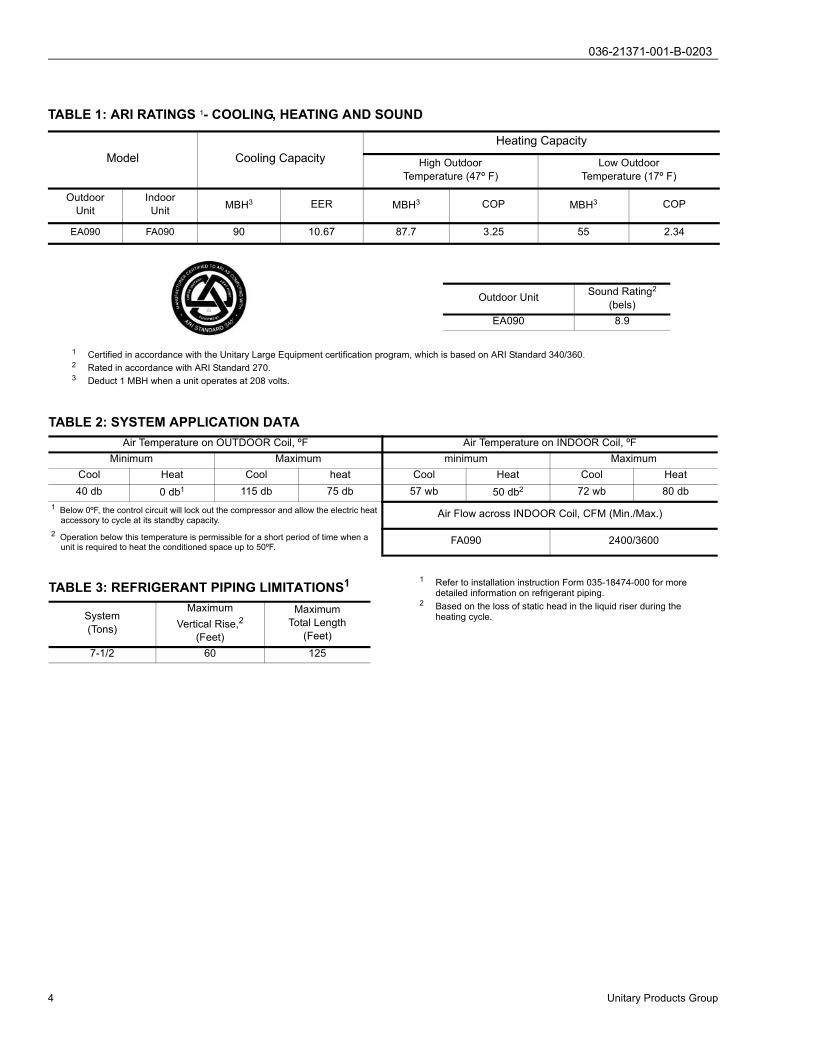
1 Certified in accordance with the Unitary Large Equipment certification program, which is based on ARI Standard 340/360.2 Rated in accordance with ARI Standard 270.3 Deduct 1 MBH when a unit operates at 208 volts.
TABLE 1: ARI RATINGS 1- COOLING, HEATING AND SOUND
Model Cooling CapacityHeating Capacity
High OutdoorTemperature (47º F)
Low OutdoorTemperature (17º F)
OutdoorUnit
IndoorUnit MBH3 EER MBH3 COP MBH3 COP
EA090 FA090 90 10.67 87.7 3.25 55 2.34
Outdoor Unit Sound Rating2
(bels)EA090 8.9
TABLE 2: SYSTEM APPLICATION DATAAir Temperature on OUTDOOR Coil, ºF Air Temperature on INDOOR Coil, ºF
Minimum Maximum minimum MaximumCool Heat Cool heat Cool Heat Cool Heat40 db 0 db1 115 db 75 db 57 wb 50 db2 72 wb 80 db
1 Below 0ºF, the control circuit will lock out the compressor and allow the electric heat accessory to cycle at its standby capacity.
Air Flow across INDOOR Coil, CFM (Min./Max.)
2 Operation below this temperature is permissible for a short period of time when a unit is required to heat the conditioned space up to 50ºF.
FA090 2400/3600
TABLE 3: REFRIGERANT PIPING LIMITATIONS1
System(Tons)
MaximumVertical Rise,2
(Feet)
MaximumTotal Length
(Feet)7-1/2 60 125
1 Refer to installation instruction Form 035-18474-000 for more detailed information on refrigerant piping.
2 Based on the loss of static head in the liquid riser during the heating cycle.

036-21371-001-B-0203
Unitary Products Group 5
SYSTEM FLEXIBILITY
The coils for both the indoor and outdoor units are not onlycircuited and headered for optimum heating and cooling per-formance, but also for ample subcooling during all modes ofoperation. The sub-cooling permits the outdoor unit to bemounted 60 feet over or under the indoor unit without anydanger of flashing liquid refrigerant during the heating or thecooling cycle.
Refer to the REFRIGERANT PIPING table above for moredetailed information on refrigerant pipe limitations.
A = 1-3/8" OD Vapor Line
B = 1-1/8" OD Vapor Line
C = Intermediate Trap - only required when a riser exceeds 50 feet.
D = Inverted Trap - only required when the horizontal run to the unit exceeds 25 feet.

036-21371-001-B-0203
6 Unitary Products Group
TABLE 4: COOLING CAPACITY - EA090
86 83 80 77 74 71 68 86 83 80 77 74 71 6872 99 7.0 59 52 45 39 32 - - 96 7.7 58 51 44 37 31 - -67 91 6.9 73 66 59 52 46 39 32 88 7.6 72 65 58 51 44 37 3162 82 6.7 82 78 71 64 57 50 43 82 7.5 82 77 70 63 56 50 4357 86 6.7 86 83 76 69 62 55 49 89 7.5 87 80 73 66 59 53 4672 102 7.1 66 58 49 41 33 - - 99 7.8 65 57 48 40 32 - -67 94 7.0 81 73 64 56 48 40 32 90 7.7 80 71 63 55 47 38 3062 84 6.8 84 82 77 69 61 52 44 84 7.5 84 81 76 68 60 52 4457 88 6.8 88 87 83 74 66 58 50 91 7.5 90 86 80 71 63 55 4772 105 7.2 73 63 53 44 34 - - 101 7.9 71 62 52 43 33 - -67 96 7.1 89 79 70 60 50 41 31 92 7.7 88 78 68 59 49 39 3062 86 7.0 86 86 83 74 64 54 45 85 7.6 85 85 83 73 64 54 4457 90 6.9 90 90 89 80 70 60 51 93 7.6 93 93 86 77 67 57 4872 106 7.2 75 65 55 45 34 - - 103 7.9 74 64 54 44 34 - -67 97 7.1 92 82 72 61 51 41 31 94 7.7 91 81 70 60 50 40 3062 87 7.0 87 87 86 75 65 55 45 87 7.6 87 87 85 75 65 55 4557 91 6.9 91 91 91 81 71 60 50 94 7.6 94 94 89 79 68 58 4872 107 7.2 78 67 56 45 35 - - 104 7.9 77 66 55 45 34 - -67 99 7.1 95 84 73 63 52 41 31 95 7.7 94 83 73 62 51 40 3062 88 7.0 88 88 88 77 66 56 45 88 7.6 88 88 88 77 66 56 4557 93 6.9 93 93 93 82 71 60 50 96 7.6 96 96 91 81 70 59 49
86 83 80 77 74 71 68 86 83 80 77 74 71 6872 93 8.5 56 49 42 35 29 - - 89 9.3 54 47 40 33 26 - -67 83 8.4 70 63 56 49 42 36 29 79 9.3 68 61 54 48 41 34 2762 79 8.2 79 75 68 61 55 48 41 76 9.0 76 73 66 60 53 46 3957 83 8.3 82 76 69 62 55 48 42 78 9.1 78 72 65 58 51 44 3772 95 8.6 63 55 46 38 30 - - 91 9.4 61 53 45 36 28 - -67 85 8.5 77 70 62 53 45 37 29 80 9.4 75 68 60 52 44 36 2762 81 8.3 81 79 75 67 59 50 42 78 9.1 78 76 74 65 57 49 4157 85 8.3 84 81 76 67 59 51 43 79 9.1 79 76 72 63 55 47 3972 97 8.7 70 60 51 41 31 - - 92 9.5 68 58 49 39 30 - -67 87 8.6 85 77 67 58 48 38 29 82 9.4 82 76 66 57 47 37 2862 82 8.4 82 82 82 72 63 53 43 79 9.2 79 79 81 71 62 52 4257 87 8.4 87 87 82 73 63 54 44 81 9.2 81 81 79 69 59 50 4072 99 8.7 72 62 52 42 32 - - 95 9.5 70 60 50 40 30 - -67 89 8.6 87 79 69 59 49 38 28 84 9.4 84 78 68 57 47 37 2762 84 8.4 84 84 84 73 63 53 43 81 9.2 81 81 82 72 62 51 4157 88 8.4 88 88 85 74 64 54 44 83 9.2 83 83 80 70 60 50 4072 100 8.7 75 64 53 43 32 - - 97 9.5 72 62 51 40 30 - -67 90 8.6 90 82 71 60 49 39 28 86 9.4 86 80 69 58 48 37 2662 86 8.4 86 86 85 75 64 53 42 83 9.2 83 83 83 72 62 51 4057 90 8.4 90 90 87 76 65 55 44 84 9.2 84 84 82 71 61 50 39
3600
2400
2850
3300
3450
Return Dry Bulb (°F)CFM WB(°F)
Return Dry Bulb (°F)
3600
Air On Evaporaor Coil
105°F 115°FTotal
Capacity 1
(MBh)
Total
Input 2
(kW)
Sensible Capacity (MBh) Total
Capacity 1
(MBh)
Total
Input 2
(kW)
Sensible Capacity (MBh)
95°FTotal
Capacity 1
(MBh)
Total
Input 2
(kW)
Sensible Capacity (MBh) Total
Capacity 1
(MBh)
Total
Input 2
(kW)
Sensible Capacity (MBh)Return Dry Bulb (°F)Return Dry Bulb (°F)
Temperature of Air on Condenser Coil
Temperature of Air on Condenser Coil
Air On Evaporaor Coil
85°F
CFM
2400
2850
3300
WB(°F)
3450

036-21371-001-B-0203
Unitary Products Group 7
The capacities shown are gross ratings. For net capacities, determine the KW requirement of the supply air blower motor per the SUPPLY AIR BLOWER PER-FORMANCE table. Convert KW to MBH by the following equation and deduct this equivalent heat from the gross cooling ratings.
Blower Motor Heat (MBH) = Blower Motor KW x 3.415Apply the following correction factors to determine the unit performance at different CFM.These ratings include the compressor KW and the following KW for the outdoor fan motor(s).
NOTE: Sensible capacity can never exceed total capacity. A higher corrected sensible capacity indicates a dry coil, and it should be reduced to the corrected total capacity.
Blower motor KW is not included. Refer to the SUPPLY AIR BLOWER PERFORMANCE table for the KW rating of the supply air blower motor at the design conditions and add this power requirement to the KW rating.
TABLE 4: COOLING CAPACITY - EA090 (CONT.)
% Nominal Supply Air CFM 80 90 100 110 120Total Capacity Correction FactorSensible Capacity Correction FactorKilowatt Correction Factor
0.9630.9350.981
0.9810.9650.992
1.0001.0001.000
1.0151.0491.008
1.0301.0981.019
Nominal Rating
86 83 80 77 74 71 68
72 85 10.2 52 45 38 31 24 - -
67 74 10.1 66 59 53 46 39 32 25
62 74 9.8 74 71 65 58 51 44 37
57 72 9.9 72 67 61 54 47 40 33
72 87 10.3 59 51 43 34 26 - -
67 76 10.2 73 67 59 51 42 34 26
62 75 9.9 75 74 72 64 56 48 39
57 73 10.0 73 71 68 60 51 43 35
72 88 10.4 66 57 47 38 28 - -
67 77 10.3 77 75 65 55 46 36 27
62 76 10.0 76 76 76 70 61 51 41
57 75 10.1 75 75 75 65 56 46 37
72 90 10.4 68 58 48 38 28 - -
67 79 10.3 79 76 66 56 46 36 25
62 78 10.0 78 78 78 70 60 50 40
57 77 10.1 77 77 76 66 56 46 36
72 93 10.3 70 60 49 38 27 - -
67 81 10.3 81 78 67 57 46 35 24
62 80 9.9 80 80 80 70 59 48 38
57 79 10.0 79 79 78 67 56 45 35
1 - These capacities are gross
ratings. For net capacity, deduct
air blower motor, MBh = 3.415 x
kW. Refer to the appropriate
Blower Performance Table for the
kW of the supply air blower motor.
2 - These ratings include the
condenser fan motors (total 1 kW)
and the compressor motors but not
the supply air blower motor.3450
3600
2400
2850
3300
Air On
Evaporaor Coil
Temperature of Air on Condenser Coil
125°FTotal
Capacity1
(MBh)
Total
Input2
(kW)
Sensible Capacity (MBh)
CFM WB(°F)Return Dry Bulb (°F)
Outdoor Unit Size 7-1/2 TonOutdoor Fan Motor KW - 60 HZ 0.83

036-21371-001-B-0203
8 Unitary Products Group
These ratings are based on an outdoor relative humidity of 72%. They include an allowance for defrost but not for the supply air blower motor heat. Refer to the BLOWER PERFORMANCE table for the KW rating of the supply air blower motor at the design conditions. Convert this KW rating to MBH using the following equation and add this equivalent heat to the heating capacity.
Blower Motor Heat (MBH) = Blower Motor KW x (3.415 MBH/KW)Use the following equation to determine the C.O.P. at any operating condition.
C.O.P. = Total MBH (including Blower Motor Heat)/[Total KW (including Blower Motor KW) x 3.415]correct the MBH and KW ratings with the following factors for different supply air CFM’s.These ratings include the compressor KW and the following KW for the outdoor fan motor(s).
NOTE: Apply these factors to the above ratings before correcting for the supply air blower heat and power requirements..
Blower motor KW is not included. Refer to the SUPPLY AIR BLOWER PERFORMANCE table for the KW rating of the supply air blower motor at the design conditions and add this power requirement to the KW rating.
UNIT MODEL EA090
OUTDOOR TEMPERATURE (F) (72% RH)CFM ID DB 0 10 20 30 40 50 60 70
2400 60 MBH 12.237 28.142 44.048 59.954 75.859 91.765 107.671 123.576
2400 KW 2.090 3.179 4.268 5.357 6.447 7.536 8.625 9.714
2400 70 MBH 9.673 25.579 41.485 57.390 73.296 89.201 105.107 121.013
2400 KW 2.576 3.665 4.754 5.844 6.933 8.022 9.111 10.201
2400 80 MBH 9.589 25.495 41.401 57.306 73.212 89.118 105.023 120.929
2400 KW 3.352 4.441 5.530 6.619 7.709 8.798 9.887 10.976
3300 60 MBH 13.565 29.471 45.377 61.282 77.188 93.094 108.999 124.905
3300 KW 1.417 2.506 3.595 4.685 5.774 6.863 7.952 9.041
3300 70 MBH 10.826 26.732 42.637 58.543 74.449 90.354 106.260 122.166
3300 KW 1.852 2.941 4.030 5.119 6.209 7.298 8.387 9.476
3300 80 MBH 10.916 26.822 42.727 58.633 74.539 90.444 106.350 122.256
3300 KW 2.679 3.768 4.857 5.946 7.035 8.125 9.214 10.303
3600 60 MBH 14.284 30.189 46.095 62.001 77.906 93.812 109.718 125.623
3600 KW 1.353 2.442 3.531 4.620 5.710 6.799 7.888 8.977
3600 70 MBH 11.720 27.626 43.531 59.437 75.343 91.248 107.154 123.060
3600 KW 1.839 2.928 4.018 5.107 6.196 7.285 8.374 9.464
3600 80 MBH 11.636 27.542 43.448 59.353 75.259 91.165 107.070 122.976
3600 KW 2.615 3.704 4.793 5.883 6.972 8.061 9.150 10.239
THE MBH AND KW VALUES DO NOT INCLUDE THE SUPPLY AIR BLOWER MOTOR.FOR NET CAPACITY, ADD THE SUPPLY AIR BLOWER MOTOR HEAT (MBH = 3.415 x KW)
Correction Factor 80 90 100 110 120MBHKW
0.961.030
0.981.015
1.001.000
1.020.985
1.040.970
Outdoor Unit Size 7-1/2 TonOutdoor Fan Motor KW - 60 HZ 0.96

036-21371-001-B-0203
Unitary Products Group 9
**These motors will always be wired for a 460 volt power supply. Refer to the wiring diagram inside the motor terminal box when the motor leads have to be reconnected for a 208 or 230 volt power supply.
TABLE 5: ELECTRIC HEAT ACCESSORY
Heater Model Nominal VoltageHeating Capacity
Nominal Defrost Supplemental Standby and EmergencyKW MBH KW MBH KW MBH KW MBH
2HS04501025A 2401
10 34.2 10 34.2 10 34.2 10 34.246A 4802
2HS04501625A 2401
16 54.7 10 34.2 16 54.7 16 54.746A 4802
2HS04502625A 2401
26 88.8 16 54.7 26 88.8 26 88.846A 4802
2HS04503625A 2401
36 123.0 16 54.7 26 88.8 36 123.046A 4802
1 For 208 volts, multiply the MBH and KW values by (208/240)^2 or 0.751.For 208 volts, multiply the MBH and KW values by (230/240)^ 2 or 0.918.
2 For 460 volts, multiply the MBH and KW values by (460/480)^2 or 0.918.
TABLE 6: BLOWER MOTOR AND DRIVE DATAIndoorUnit
Model
MotorHP
BlowerHP
Adjustable Motor Pulley Fixed Blower Pulley BeltPitch Diameter,
(in.)Bore,(in.)
Pitch Diameter,(in.)
Bore,(in.) Designation Pitch Length,
(in.)FA090 1-1/2 690 - 920 2.8 - 3.8 7/8 7.5 1 A36 37.3
*Motor Specifications:
• 1750 RPM • inherently protected• 208/230/460-3-60** • 1.15 service factor• solid base • permanently lubricated
ball bearings• 56 frame
TABLE 7: SUPPLY AIR BLOWER PERFORMANCE FA0901,2
7.5 HEAT PUMP BLOWER PERFORMANCEESP CFM RPM Watts CFM RPM Watts CFM RPM Watts CFM RPM Watts CFM RPM Watts CFM RPM Watts0.2 4152 895 1877 4014 892 1844 3725 819 1378 3443 774 1201 3219 734 1015 2949 691 8550.4 3901 900 1752 3753 897 1714 3404 823 1255 3091 777 1084 2818 736 899 2503 694 7440.6 3617 905 1607 3478 902 1569 3000 837 1118 2671 855 943 2149 740 762 - - -0.8 3232 911 1443 3083 907 1406 2468 831 957 - - - - - - - - -1 2740 916 1222 2431 913 1185 - - - - - - - - - - - -
0 turns 1 turn 2 turns 3 turns 4 turns 5 turns
1 Available static pressure in IWG to overcome the resistance of the duct system and any accessories added to the unit. Refer to the table above for additional motor and drive data and to Table 10 for the resistance of these accessories.
2 Refer to Form 515.41-AD1 for blower performance curves.

036-21371-001-B-0203
10 Unitary Products Group
TABLE 8: SUPPLY AIR PLENUM PERFORMANCE DATA
INDOOR UNIT
MODEL FA
CFM
FACE VELOCITY(FPM)
ANGLE OF DEFLECTION
VERTICALLOUVERS1
(PLAN VIEW)
HORIZONTALLOUVERS2
(ELEVATIONVIEW)
VERTICALLOUVERS1
(PLAN VIEW)
HORIZON-TAL
LOUVERS2
(ELEVATIONVIEW)
VERTICALLOUVERS1
(PLAN VIEW)
HORIZONTALLOUVERS2
(ELEVATIONVIEW)
THROW(FEET3)
SPREAD(FEET)3
THROW(FEET)3
SPREAD(FEET)3
THROW(FEET)3
SPREAD(FEET)3
MIN. MAX. MIN. MAX DROP (FEET)4 MIN. MAX MIN. MAX DROP (FEET)4 MIN. MAX. MIN. MAX. DROP (FEET)4
090
2400 615 47 74 20 29 19 9 34 53 23 33 17 8 26 39 45 65 9 52700 690 53 83 22 32 20 10 39 59 25 36 18 9 29 45 48 71 10 53000 770 59 92 24 35 21 10 42 66 27 40 19 9 32 50 52 78 10 53300 845 65 101 26 38 21 10 46 73 29 44 19 9 35 55 56 85 10 53600 920 71 110 28 41 22 11 50 79 32 47 20 10 38 60 60 91 11 6
1 Adjusting the vertical louvers will vary the throw, the spread and the drop.2 Adjusting the horizontal louvers will only vary the drop.3 The velocity of the air will be 125 ft./min. at the minimum distance and 80 ft./min. at the maximum distance.4 The velocity of the conditioned air at the bottom of the drop will be 50 ft./min. Drafts will occur if the drop extends into the occu-
pied level of the conditioned space.
� � �
� � � � �
� � �
� � � � �
� � �
� � � � �
� � �
� � � � � 18˚� � �
� � � � � 18˚ � � �
� � � � �
18˚
FIGURE 3: FA090 AIRFLOW CHART
7.5-ton Heat Pump
2400
2600
2800
3000
3200
3400
3600
3800
4000
4200
4400
0 0.1 0.2 0.3 0.4 0.5 0.6 0.7 0.8 0.9 1 1.1
Static
CF
M
O turns
1 turn
2 turns
3 turns
4 turns
5 turns

036-21371-001-B-0203
Unitary Products Group 11
ACCESSORIES (FIELD-INSTALLED)
Three-Phase Electric Heaters are available in several capaci-ties to provide maximum flexibility. The heater can beselected to precisely meet the supplemental heating require-ment of the conditioned space.
These heaters are designed for easy field-installation overthe supply air opening of the indoor unit. They have beentested by Underwriters’ Laboratories and will be shipped witha UL label. Every heater will be fully protected against exces-sive current and temperature by fuses and two high limit ther-mostats.
Units with Electric Heat will require only one power supply forboth the heating elements and the supply air blower motor,and the power wiring can be protected by either dual ele-ment/time delay fuses or an inverse time circuit breaker.
Supply Air Plenums and Return Air Grilles (expanded metal)are available for free-standing indoor units located in the con-ditioned space. Both accessories are finished to match theexterior of the basic unit, and both can be applied with eithervertical or horizontal units. The supply air plenums are fullyinsulated and have double-deflection, adjustable grilles.
Base Sections are available to raise vertical indoor unitsabove the floor. Outdoor air may be introduced through thesebases by cutting an access opening for the outdoor air ductconnection. These bases are finished to match the exterior of
the basic unit. They may have to be insulated in the field forcertain applications.
Decorative Coil Guards can be field installed to enhance pro-tection of the unit.
Thermostats with either manual or automatic changeover areavailable for precise control of the temperature within theconditioned space. The manual thermostat has a four-posi-tion selector switch - COOL, OFF, HEAT, and EMERGENCYHEAT, and three stages of control - one stage of cooling andtwo stages of heating. The automatic thermostat has a three-position selector switch - OFF, AUTOMATIC and EMER-GENCY HEAT, and four stages of control - two stages ofcooling and two stages of heating.
Both thermostats have a two-position fan switch, AUTO andON to provide intermittent or continuous blower operation.
NOTE: The automatic changeover thermostat must be usedon units equipped with a field-supplied economizer.
The first cooling stage of the automatic thermostatwill only control the position of the reversing valve;the system will still operate with only one stage ofcooling.
The EMERGENCY HEAT position on the selectorswitch and the second stage of heating will only func-tion on systems with an electric heat accessory.
TABLE 9: STATIC RESISTANCES FOR UNIT ACCESSORIES (IWG)
Unit Model AccessoryCFM
2400 2700 3000 3300 3600
FA090ELECTRIC HEAT
10 KW 0.01 0.01 0.01 0.02 0.0216 KW 0.01 0.02 0.02 0.03 0.0426 KW 0.03 0.04 0.05 0.06 0.0736 KW 0.05 0.07 0.08 0.10 0.11
Supply Air Plenum 0.03 0.03 0.04 0.05 0.06Return Air Grille 0.02 0.03 0.04 0.05 0.06

036-21371-001-B-0203
12 Unitary Products Group
CLEARANCES
CENTER OF GRAVITY
Overhead (Top)1
1 Unit must be installed outdoors. Overhanging structures or shrubs should not obstruct air discharge outlet.
120”Front(Piping and Access Panels 30”
Left Side 24”Right Side 24”Rear 24”
Bottom2
2 Adequate snow clearance must be provided if winter operation is expected.
0” UnitDim. (inches.)
A B C D
EA090 70-1/8 32 29-5/8 16-1/2
FIGURE 4: UNIT DIMENSIONS & CLEARANCES - OUTDOOR UNITS
A�I�R�
OU�T�
A�I�R�
I�N�
A�I�R�
OU�T�
2�-�3�/�4�
3�2�
2�-�1�/�4�
3�2�-�1�/�2� 7�0�-�1�/�8�
8�-�3�/�4�5�-�3�/�8�
C�ON�T�R�OL��B�OX�
A�C�C�E�S�S�
GU�A�GE�
L�I�N�E�
A�C�C�E�S�S� 3�9� 1�-�3�/�8�*��OD��
V�A�P�OR��L�I�N�E�
5�/�8�*��OD�
L�I�QU�I�D��L�I�N�E�
1�4�-�3�/�4�
7�/�8��D�I�A�
C�ON�T�R�OL��W�I�R�I�N�G�
E�N�T�R�Y�
C�OM�P�R�E�S�S�OR��A�N�D��
C�ON�D�E�N�S�E�R��F�A�N��M�OT�OR�
A�C�C�E�S�S�1�-�3�/�8��D�I�A�.�
P�OW�E�R��W�I�R�I�N�G�
E�N�T�R�Y�
6�-�3�/�4�
C�ON�D�E�N�S�E�R��F�A�N��M�OT�OR�
A�C�C�E�SS
7�/�8�"��K�N�OC�K�OU�T�
A�C�C�E�S�S�OR�Y��W�I�R�I�N�G�
E�N�T�R�Y�
6�-�3�/�4�
5�-�7�/�8�
*�A�I�R��ON��3��S�I�D�E�S
EA090(7-1/2 Ton)
All dimensions are in inches. They aresubject to change without notice. Certifieddimensions will be provided upon request.

036-21371-001-B-0203
Unitary Products Group 13
ACCESSORIES
• ELECTRIC HEATER - Add 14-1/4” to unit height when used.
• SUPPLY AIR PLENUM - Add 27-1/2” to unit height when used.
• BASE - Add 20” to unit height when used.
MINIMUM CLEARANCESSide with RETURN AIR opening 24”Side with SUPPLY AIR opening 24”1
1 Overall dimension of the unit will vary if an electric heater, a supply air plenum or a base is used.
Side with PIPING CONNECTIONS 52”2
2 This dimension is required for removal of the coil. Only 26” is required for normal servicing.
Side opposite PIPING CONNECTIONS 12”Side with access for both POWER & CONTROL WIRING --3
3 Although no clearance is required for service and operation, some clearance may be required for routing the power wiring and the control wiring.
Bottom --4
4 Allow enough clearance to trap the condensate drain line.
FIGURE 5: UNIT DIMENSIONS & CLEARANCES- INDOOR UNITS

036-21371-001-B-0203
14 Unitary Products Group
FIGURE 6: FIELD WIRING
������ ������ � �����������
��������� ������ � ��������������� �� ��� �!���� ���� " ��"
��! ���� ��" �"�������" � !�#
�� $��% &� �� ������% �� ��' %���( � �����' )'��%%* ��
�+� ��� , ���% %� ���( $ �� �� ���%�� ���� �� �� �� ��'��� �$
%'� %- � ����� � �� �+� ��� ��'� , ,(.�''% �$ �� ��%�� ����
�' ��� /��..% &��� �� ��� �� ��� ���''� (-
*All OUTDOOR Units and all HEAT PUMP onlyINDOOR Units require dual element, time delayfuses. Circuit breakers can be used in lieu of fusesfor indoor units with an electric heat accessory.
1 Only required when an electric heat accessory isused.
2 Only required with a 16 or 26KW electric heataccessory is used.
3 Only required with a 36KW electric heat accessoryis used.

036-21371-001-B-0203
Unitary Products Group 15
FIGURE 7: ACCESSORY DIMENSIONS
Install the control wiring per basic unit instructionForm 035-18475-000. DO NOT route any field controlwiring through the plenum.
WITHOUT ELECTRIC HEAT - Install the power andthe control wiring per basic unit instruction Form035-18475-000. DO NOT route any wiring through theplenum and DO NOT remove this knockout.

036-21371-001-B-0203
16 Unitary Products Group
TABLE 10: PHYSICAL DATA (OUTDOOR UNIT)DESCRIPTION UNIT MODEL - EA090
Compressor1 Rating - tons 7-1/2
FansQuantity 2Diameter - inches No. of Blades 24/3Nominal CFM 7800
Fan Motors2 HP 3/4RPM 1100
Coil
Rows Deep x Rows High 2 x 36Finned Length - inches 96Face Area - square feet 24.00Tube (Copper) OD - inches 3/8Fins (Aluminum) per inch 16
Refrigerant-22 (Lbs.)Holding Charge 1.50Operating Charge3 18.8
Pumpdown Capacity4 24.6
Unit Weight (Lbs.)Shipping 510Operating 505
1 These compressors are fully hermetic.2 These PSC motors are directly connected to the outdoor fans and have inherent protection, ball bearings and a 48 frame. Rotation
(when viewing shaft end of motor) -090 = CW.3 Includes outdoor unit and matched indoor blower unit, but no piping.4 Based on a 95 ºF ambient.
TABLE 11: PHYSICAL DATA (INDOOR UNIT)DESCRIPTION UNIT MODEL - FA090
Coil
Rows Deep x Rows High 3 x 32Finned Length - inches 45.5Face Area - square feet 10.1Tube (Copper) OD - inches 3/8Fins (Aluminum) per inch 13
Centrifugal Blower (Forward Curve) Diameter x Width - inches 15 X 15Blower Motor1 Nominal Rating - HP 1-1/2
Filters (Throwaway)Quantity Per Unit - 16” x 25” x 1” 4Total Face Area - square feet 11.1
Refrigerant-22 (Lbs.)Holding Charge2 -
Pumpdown Capacity3 16.5
Unit Weight4 (lbs.)Shipping 425Operating 385
Accessory Operating Weights (Lbs.)
Electric Heaters5
10 KW 6316 KW 6626 KW 7136 KW 74
Supply Air Plenum 102Base 60Return Air Grille 15
Shipping Volume (Basic Unit) - cubic feet 45
1 All of these 1750 RPM motors have a solid base, a 56 frame, a 1.15 service factor, inherent protection & permanently lubricated ball bearings. Refer to Table 7 for additional motor & drive data.
2 Although every indoor unit is shipped with a small holding charge, this charge will be lost during installation. Loss of all refrigerant must be reclaimed during installation - NOT vented into the atmosphere. Refer to the above table on the OUTDOOR unit for the system operating charge.
3 Based on a 80ºF ambient.4 Refer to Installation Instruction Form 035-18475-000 for the distributed weight of these indoor units.5 Refer to Table 13 for additional electric heat accessory data.

036-21371-001-B-0203
Unitary Products Group 17
To determine the total circuit length, add the following distances:1 - Outdoor Unit to Indoor Unit ________2 - Indoor Unit to Thermostat ________3 - Thermostat to Indoor Unit ________4 = Indoor Unit to Outdoor Unit ________
Total Circuit Length ________
TABLE 12: PHYSICAL DATA - ELECTRIC HEAT ACCESSORIES
DescriptionNominal Heater Capacity
10 kW 16 KW 26 KW 36 KW
Heater Elements
% Nickel 59.2% Chromium 16.0Coil ID - inches 9/32Watt Density - watts/sq.in. 59Rows Deep 1 2 3 4
Face Area - square feet 3.0
TABLE 13: ELECTRICAL DATA - OUTDOOR UNIT
ModelEFB
Compressor Outdoor Fan Motor Min.CircuitAmps
Max.FuseSize
Min. WireSize,1AWG
PowerSupply RLA LRA Power
FactorPowerSupply Qty. FLA
(Each)
090A25 200/230-3-60 25.6 190.0
0.94 @ 208V208/230-1-60 2 3.03 38.1 60 8
0.84 @ 230V46 460-3-60 12.8 95.0 0.86 460-1-60 2 1.6 19.2 30 10
1 Based on three, 60ºC insulated copper conductors in steel conduit.
TABLE 14: INDOOR UNIT - HEAT PUMP ONLYBlowerMotor
HP
PowerSupply FLA
Max. FuseSize,1AMPS
1 Dual element, time delay fuses.
FA090
1-1/2208-3-60 5.2 15230-3-60 5.0 15460-3-60 2.6 15
TABLE 15: CONTROL WIRE SIZING
Wire Size Max. TotalCircuit Length, (Ft.)
#19 Solid 130#18 Solid 170#18 Stranded 180#16 Stranded 270#14 Stranded 455#12 Stranded 730

036-21371-001-B-0203
18 Unitary Products Group
TABLE 16: HEAT PUMP WITH ELECTRIC HEAT1
NominalHeaterKW2
Power Supply HeaterFLA
Total UnitAmpacity
AMPS
Max, FuseSize,3AMPS
Min. WireSize,4AWG
FA090
10208-3-60 20.8 31.3 35 8230-3-60 24.1 35.1 40 8460-3-60 12.0 17.6 20 12
16208-3-60 33.4 46.9 50 8230-3-60 38.5 53.1 60 6460-3-60 19.2 26.7 30 10
26208-3-60 54.2 73 80 4230-3-60 62.5 83.2 90 4460-3-60 31.3 41.7 45 8
36208-3-60 75.1 99 110 3230-3-60 86.6 113.3 125 2460-3-60 43.3 56.7 60 6
1 Unit with an electric heat accessory will always be wired for a single power supply.2 Refer to the Heating Capacity table for the actual KW and MBH ratings of each heater at the different voltages.3 Inverse time circuit breakers may be used in lieu of dual element, time delay fuses.4 Based on three, insulated copper conductors in steel conduit: 60ºC wire when the total unit ampacity is below 100 amps; 75ºC
wire when the total unit ampacity is 100 amps and above.

036-21371-001-B-0203
Unitary Products Group 19

Subject to change without notice. Printed in U.S.A. 036-21371-001-B-0203Copyright © by Unitary Products Group 42003. All rights reserved. Supersedes: 036-21371-001-A-0402
Unitary 5005 NormanProducts York OKGroup Drive 73069