Embed Size (px)
Citation preview

harris.com
Yemen ISR
CONOPS and Capabilities
8-Nov-13
THIS INFORMATION WAS APPROVED FOR PUBLISHING PER
THE ITAR AS “BASIC MARKETING INFORMATION OF DEFENSE
ARTICLES” OR PER THE EAR AS “ADVERTISING PRINTED MATTER”.

| 2 Presentation Name | 8-Nov-13
Yemen ISR – Table of Contents
1.0 Overview
2.0 CONOPS Example
3.0 Station Assets and Architecture
| 3 Presentation Name | 8-Nov-13
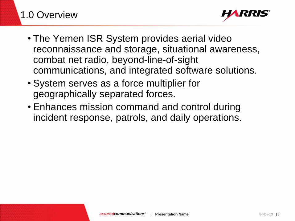
1.0 Overview
• The Yemen ISR System provides aerial video reconnaissance and storage, situational awareness, combat net radio, beyond-line-of-sight communications, and integrated software solutions.
• System serves as a force multiplier for geographically separated forces.
• Enhances mission command and control during incident response, patrols, and daily operations.

| 4 Presentation Name | 8-Nov-13
2.0 CONOPS
• Assumption: Ground, Air and Marine forces are arrayed and stationed along the coast of Yemen.
• Using Harris C4ISR assets, these forces are able to communicate and coordinate their efforts during normal operations.
• Scenario: Aerial video intelligence transmitted to lower echelon forces captures an incident between two outposts. A joint response between Ground, Air and Marine forces is required to counter an attack. Upper echelon Headquarters are notified and able to quickly coordinate and deploy their forces to the Area of Operations.
Coastal Forces Aircraft Video Intelligence

| 5 Presentation Name | 8-Nov-13
2.0 CONOPS

| 6 Presentation Name | 8-Nov-13
2.0 CONOPS
• The above diagram shows the configuration for forces arrayed in a common Area of Operation (AO). It is assumed that the Aircraft is airborne and has full line-of sight (LOS) to the ground and marine resources.
• Video from the Aircraft System is streamed to all members in the AO using multicast routing.
• In order to maximize video speed and resolution (for this scenario), it is recommended that full member network node size is limited to 4 nodes (Aircraft, Marine, Groundstation, and Tactical Convoy Commander) and assets should be within a 35km span. All full members are able to receive (Rx) and transmit (Tx) data, including Situational Awareness (SA).
• Guest node membership is available to all remaining assets (configured for ANW2) including those that join the AO from other units. These assets are able to Rx the Aircraft video stream without loading down the network. Guest members’ GPS coordinates are not updated in the Common Operational Picture (COP), and are unable to Tx or relay data.
• All members (full and guest) can Tx and Rx on the Combat Net Radio (CNR) voice channel.
35km
Network Span

| 7 Presentation Name | 8-Nov-13
2.0 CONOPS
• As mission needs dictate, additional forces may be deployed to the AO. These assets join the network as guests, enabling them to Rx the target video intelligence using Falcon C2View.
• Tactical Chat provides messaging service to full member assets.
• Voice communication is available among all assets.
• Guest members are able to Rx the SA data of the primary force attached to the AO and display the COP with Falcon Command.
• Although guest members can be outside of the recommended 35km span, they must meet a minimum Rx signal strength (configurable) for the network.
35km
Network Span
Falcon Command COP
Falcon C2View

| 8 Presentation Name | 8-Nov-13
2.0 CONOPS – Adaptive Network
• The ANW2 network is capable of changing on the fly. In our scenario for example, an adjacent unit is converging on an objective with the primary unit. As these forces approach the objective, real-time updates to the COP becomes necessary in order to coordinate their efforts. The connections between the Aircraft, Ship #1 and the second TC CDR can be modified such that Ship #1 retains guest membership while the TC CDR gets promoted to full membership and enters the COP.
35km
Network Span
Falcon Command COP
35km
Network Span
Falcon Command COP
TC CDR #1
TC CDR #2
TC CDR #1

| 9 Presentation Name | 8-Nov-13
2.0 CONOPS
• Groundstations have long range HF communications to Headquarters.
• Wireless Messaging Terminal and Tactical Chat provide messaging services between locations.
• Critical intelligence images and SA data can be forwarded to Headquarters.
Falcon Command COP
Falcon C2View
Wireless Messaging
Terminal

| 10 Presentation Name | 8-Nov-13
3.0 Station Assets and Architecture
• The Yemen ISR System is composed of :
– Mulitband Networking Radios (RF-7800M) providing secure voice and high-speed networked data services.
– Wideband HF Radios (RF-7800H) providing beyond line of sight voice and high-speed data.
– Tactical Video Processors (RF-7400E-VP) enable full motion video streaming, storage, and optimization of video parameters matching radio capabilities.
– Mobile Computing Platforms (RF-7800N-CP) integrate video, voice and data communications and provides a managed Ethernet switch for incorporating into existing network infrastructure.
– Rugged Laptops (CF-53/CF-19) with pre-loaded software:
• Falcon Command - Battle Management and Situational Awareness
• Falcon C2View – C4ISR video management
• Tactical Chat – Messaging Services
• Wireless Messaging Terminal – Tactical Email Service
• These assets and capabilities are divided up among 5 types of locations:
– Headquarters (x 2)
– Groundstation (x 10)
– Ship Board (x 8)
– Aircraft (x 12)
– Patrol Vehicle (x 30)

| 11 Presentation Name | 8-Nov-13
3.0 Station Assets and Architecture
• Headquarters:
*** Final System may differ from picture above ***
| 12 Presentation Name | 8-Nov-13
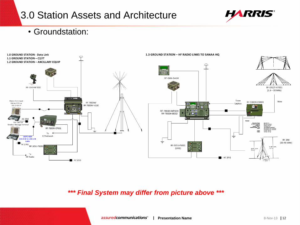
3.0 Station Assets and Architecture
• Groundstation:
*** Final System may differ from picture above ***

| 13 Presentation Name | 8-Nov-13
3.0 Station Assets and Architecture
• Ship Board:
*** Final System may differ from picture above ***

| 14 Presentation Name | 8-Nov-13
3.0 Station Assets and Architecture
• Aircraft:
*** Final System may differ from picture above ***

| 15 Presentation Name | 8-Nov-13
3.0 Station Assets and Architecture
• Patrol Vehicle:
*** Final System may differ from picture above ***


![[XLS]minsvyaz.ruminsvyaz.ru/common/upload/docs/2007061917193vq.xls · Web viewINTRALINK IDR-38 INTRALINK ISR-71 INTRALINK ISR-81 INTRALINK ISR-13 INTRALINK ISR-15 INTRALINK ISR-18](https://img.dokumen.tips/doc/110x75/5b1d3ffb7f8b9acf678b6c15/xls-web-viewintralink-idr-38-intralink-isr-71-intralink-isr-81-intralink-isr-13.jpg)