Embed Size (px)
Citation preview
YAWLEditor Technical Manual
Lindsay Bradford
January 18, 2008
1 Introduction
This is a technical manual for the YAWLEditor (currently at version 2.0). Its intended audi-ence is assumed to have a strong technical background in programming, software design ingeneral, and in the semantics of YAWL. More specifically, Java and UML are used to expressprogramming and design concepts.
This manual is intended to give the reader an introduction and insights into to the editor’sdesign. Please read it before making significant changes to the environment. There are many“odd” features of the editor’s codebase that happen to be that way for very good reasons. Manyof these are legacy concepts from the initial desire to have a prototype. Regardless, however,changing them without appreciating why they are there in the first place has significant po-tential for causing the unprepared long nights, excess caffeine consumption, and a thoroughexploration of one’s knowledge-base of expletives.
There are three main sections to the document. Section 2 describes the very foundations ofthe editor, in terms of it’s core graphing library, the breakdown of packages, extensions made tothe graphing library, and how the software is to be compiled and deployed. Section 3 describesbehaviour that builds upon these foundations, some aspects of which are likely surprise theuninitiated. Section 4 discusses some ideas on possible changes that the author believes shouldbe addressed at some stage in the editor’s life.
2 Foundations
This section describes the very foundations upon which the YAWLEditor has been built. Theeditor has been written in such a way that the core graphing library, JGraph, forms the veryheart of the application. The author’s considered opinion is that a decision to replace the coregraphing library is a decision to rewrite the editor from scratch. It’s reach goes too far, and istoo tightly coupled to the rest of the code for the editor to be considered anything other than an“application of JGraph”.
Section 2.1 covers the motivation for, and basics of using JGraph. Section 2.2 gives a high-level tour of the Java packages of the editor, introducing the nature of classes that are to befound in each package and highlights packages of particular importance. Section 2.3 introduceshow the base JGraph library has been extended to achieve the YAWL editor’s key graphingfunctionality. Section 2.4 describes interesting aspects of the editor’s build script that are not“typical” for constructing software.
YAWLEDITOR TECHNICAL MANUAL - PAGE 1 OF 22

2.1 JGraph
At the inception of the YAWLEditor project, a number of desired requirements for the editorwere listed by the drivers of the project. The editor was to be:
• freely available,
• runnable heterogeneously,
• easy to develop,
• inter-operate easily with the YAWL Engine,
• easy to deliver and run.
The greatest impediment to delivering a prototype IDE for YAWL was that of an adequatelypowerful graphing library. The project could only show quick outcomes by relying on a third-party graphing library that also enabled these requirements.
At the time, the JGraph drawing package was the only package to meet these requirementsfrom the perspective of a drawing environment for YAWL. A close second was the GEF drawingframework that comes with the Eclipse IDE. The final decider against GEF, however, was therequirement that the editor be a plugin to Eclipse, and that users of the editor would needEclipse as a base environment to run within. The authors of GEF stated at the time that it mightbe possible to run GEF independently of Eclispe, but that those who were to try were on theirown if they encountered problems. To the best of the author’s knowledge, JGraph remains thebest choice for the above requirements to this date.
The requirements are re-listed below with a brief description per requirement of JGraph’smatch to the requirement:
Freely available: Written in Java, released under LGPL. There were no runtime environmentlicensing costs for the language, and the library was free to use in programming effortsso long as the LGPL requirements were respected.
Runnable heterogeneously: Java programs allows a high likelihood that they will run withlittle to no changes on different operating systems with compatible JREs. Also, fewheterogeneous languages besides Java and C# had a rich enough GUI environment to beconsidered viable.
Easy to develop: Again, Java is one of the best supported programming languages in terms oflearning and adoption. Though the library was not exactly easy to develop with, it wasthe only free stand-alone Java library being actively supported at the time.
Inter-operate easily with the YAWL Engine: The engine was written in Java, and to lever-age as much of what the engine had to offer as possible, the path of least effort was to callengine API methods in the same language.
Easy to deliver and run: JGraph could be incorporated into an application to produce a stan-dalone Java application. GEF, which shared many of the above requirements until thispoint required the Eclipse IDE to run, and expected an application using GEF to be writ-ten as an Eclipse plugin. At the time, this was not a trivial exercise for an end-user toaccomplish. Opinion by the project owners at the time was that they also disliked the ideaof requiring such a large IDE as a pre-requisite for trying the editor.
YAWLEDITOR TECHNICAL MANUAL - PAGE 2 OF 22
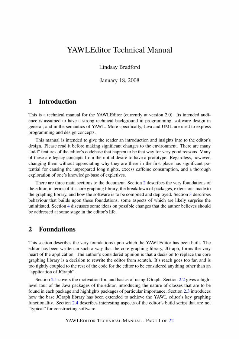
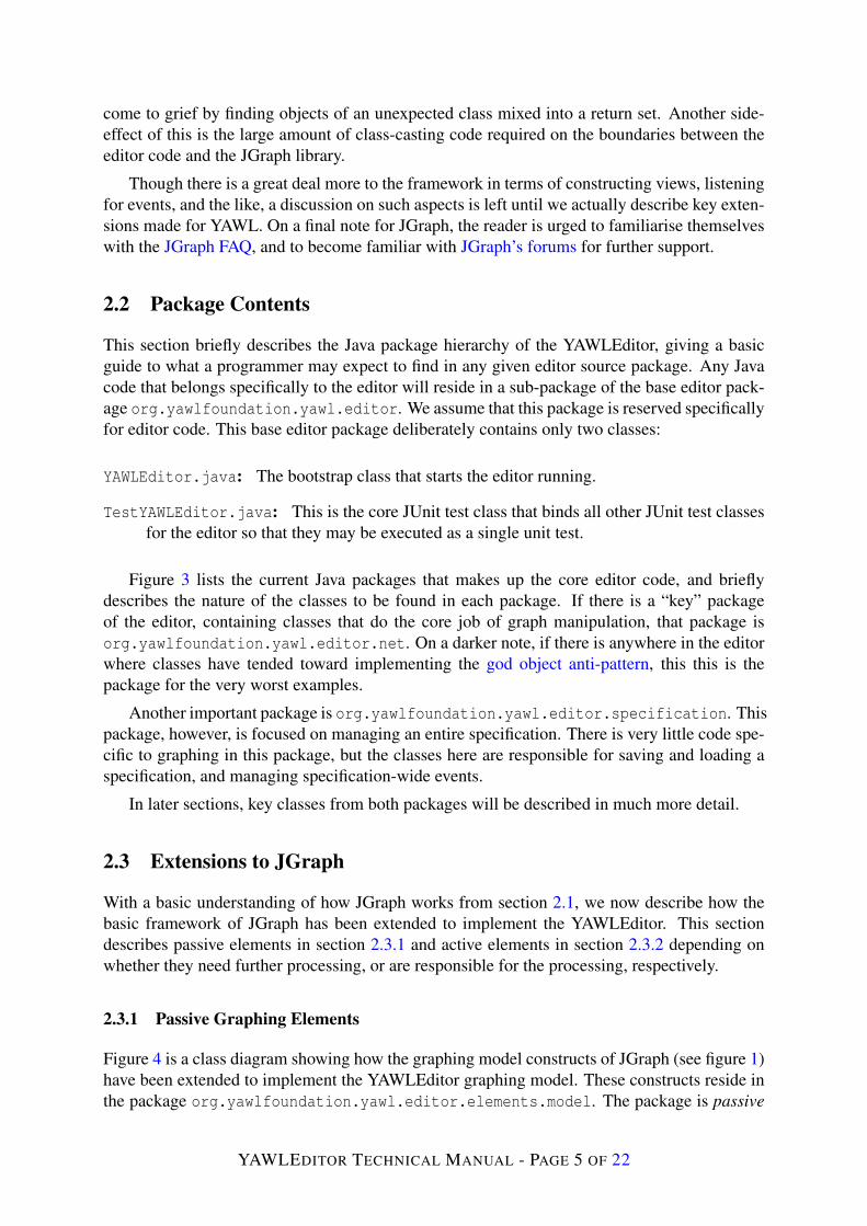
JGraph can be a daunting library to understand initially. The reader is directed to the JGraphtutorial for an official discussion of the framework. The author initially struggled with thistutorial and eventually realised that the top-down approach they used did not address certainkey concepts. A bottom-up approached worked better for the author, and is supplied here inthat hopes that it will help in understanding the framework quickly. A small class diagram ofthe “‘core” JGraph model primitives1 is supplied in figure 1.
o r g . j g r a p h . g r a p h
G r a p h C e l l
E d g eP o r t
c h i l d o f
*
1
c h i l d o f
0 - 1*
h a s s o u r c e*0 - 1
h a s t a r g e t *0 - 1
Figure 1: A class diagram of the primitive model classes of JGraph
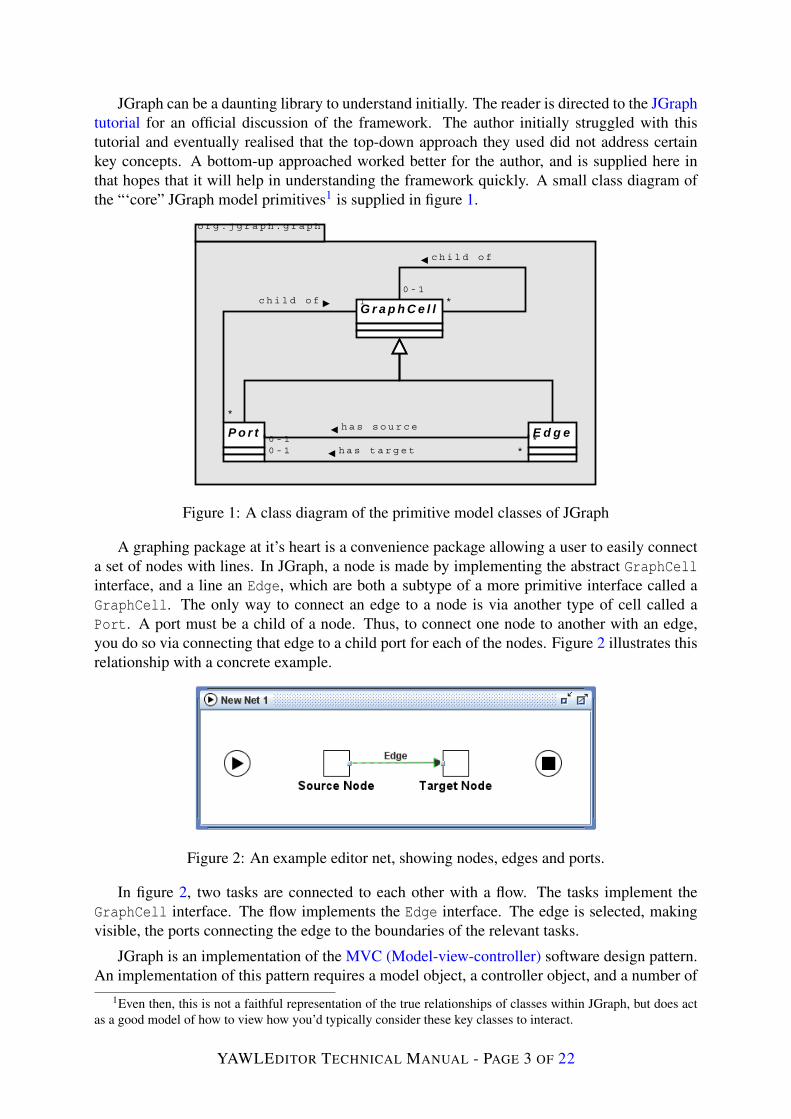
A graphing package at it’s heart is a convenience package allowing a user to easily connecta set of nodes with lines. In JGraph, a node is made by implementing the abstract GraphCellinterface, and a line an Edge, which are both a subtype of a more primitive interface called aGraphCell. The only way to connect an edge to a node is via another type of cell called aPort. A port must be a child of a node. Thus, to connect one node to another with an edge,you do so via connecting that edge to a child port for each of the nodes. Figure 2 illustrates thisrelationship with a concrete example.
Figure 2: An example editor net, showing nodes, edges and ports.
In figure 2, two tasks are connected to each other with a flow. The tasks implement theGraphCell interface. The flow implements the Edge interface. The edge is selected, makingvisible, the ports connecting the edge to the boundaries of the relevant tasks.
JGraph is an implementation of the MVC (Model-view-controller) software design pattern.An implementation of this pattern requires a model object, a controller object, and a number of
1Even then, this is not a faithful representation of the true relationships of classes within JGraph, but does actas a good model of how to view how you’d typically consider these key classes to interact.
YAWLEDITOR TECHNICAL MANUAL - PAGE 3 OF 22

view objects. Very basic versions of each type of class are supplied via DefaultGraphModel,JGraph and GraphLayoutCache for the model, controller and views, respectively. Implemen-tations of the interfaces listed in figure 1 must be placed within a DefaultGraphModel, to beconsidered part of that graph.
An important conceptual note must be made here on how to appropriately use JGraph:
A change to the graph model will only be recognised and responded to if donethrough key methods of the view, controller or graph model objects. If you directlychange the color of a node, say, by programatically updating its colour directly, thecontroller will not know to inform the various views of that node that the colour haschanged, and that they must now redraw themselves.
All changes made to a graph ultimately must go through one of the three methods ofinsert(), remove(), and edit() on DefaultGraphModel. As stated earlier, failure to makechanges via these methods will leave the views out of sync with the base model. It will alsonot record those changes as undoable events, which is typically automatically handled by theJGraph framework. Note that these methods are also supplied on the view and controller classes.It is sometimes easier to use one of these classes, if that is the level that your own code has beenworking on. Note, however, that especially with the view class, things don’t always work asexpected. Some attribute changes will not be reflected in the model, if done from the view.
Changing attributes on JGraph objects warrants some explanation. When first building anobject for placement in a JGraph, the programmer is expected to load a number of attributesinto a HashMap container, and apply these attributes to the object via the map. The object canthen be added to the graph via a call to the graph’s insert() method. Example editor code issupplied in listing 1 to illustrate the point.
Listing 1: Setting attributes on a model objectprivate void buildContent() {
HashMap map = new HashMap();
GraphConstants.setLineEnd(map , GraphConstants.ARROW_TECHNICAL);GraphConstants.setEndFill(map , true);GraphConstants.setLineStyle(map , GraphConstants.STYLE_ORTHOGONAL);GraphConstants.setBendable(map , false);GraphConstants.setEditable(map , true);
GraphConstants.setDisconnectable(map , true);GraphConstants.setConnectable(map , true);
getAttributes().applyMap(map);
setPredicate("true()");setPriority (0);
}
Listing 1 shows code for setting key attributes of flow relations, which are a kind of edgewithin YAWL. The GraphConstants class is used to ensure that the hashmap is built only withtype-safe data that is compatible with a given attribute.
Note also that a great deal of the API for JGraph requires that arrays of the most basic JavaObject be passed around. The JGraph tutorial lists a number of reasons why they feel this isa necessary part of the framework. However, as a user of the framework, the author has often
YAWLEDITOR TECHNICAL MANUAL - PAGE 4 OF 22
come to grief by finding objects of an unexpected class mixed into a return set. Another side-effect of this is the large amount of class-casting code required on the boundaries between theeditor code and the JGraph library.
Though there is a great deal more to the framework in terms of constructing views, listeningfor events, and the like, a discussion on such aspects is left until we actually describe key exten-sions made for YAWL. On a final note for JGraph, the reader is urged to familiarise themselveswith the JGraph FAQ, and to become familiar with JGraph’s forums for further support.
2.2 Package Contents
This section briefly describes the Java package hierarchy of the YAWLEditor, giving a basicguide to what a programmer may expect to find in any given editor source package. Any Javacode that belongs specifically to the editor will reside in a sub-package of the base editor pack-age org.yawlfoundation.yawl.editor. We assume that this package is reserved specificallyfor editor code. This base editor package deliberately contains only two classes:
YAWLEditor.java: The bootstrap class that starts the editor running.
TestYAWLEditor.java: This is the core JUnit test class that binds all other JUnit test classesfor the editor so that they may be executed as a single unit test.
Figure 3 lists the current Java packages that makes up the core editor code, and brieflydescribes the nature of the classes to be found in each package. If there is a “key” packageof the editor, containing classes that do the core job of graph manipulation, that package isorg.yawlfoundation.yawl.editor.net. On a darker note, if there is anywhere in the editorwhere classes have tended toward implementing the god object anti-pattern, this this is thepackage for the very worst examples.
Another important package is org.yawlfoundation.yawl.editor.specification. Thispackage, however, is focused on managing an entire specification. There is very little code spe-cific to graphing in this package, but the classes here are responsible for saving and loading aspecification, and managing specification-wide events.
In later sections, key classes from both packages will be described in much more detail.
2.3 Extensions to JGraph
With a basic understanding of how JGraph works from section 2.1, we now describe how thebasic framework of JGraph has been extended to implement the YAWLEditor. This sectiondescribes passive elements in section 2.3.1 and active elements in section 2.3.2 depending onwhether they need further processing, or are responsible for the processing, respectively.
2.3.1 Passive Graphing Elements
Figure 4 is a class diagram showing how the graphing model constructs of JGraph (see figure 1)have been extended to implement the YAWLEditor graphing model. These constructs reside inthe package org.yawlfoundation.yawl.editor.elements.model. The package is passive
YAWLEDITOR TECHNICAL MANUAL - PAGE 5 OF 22
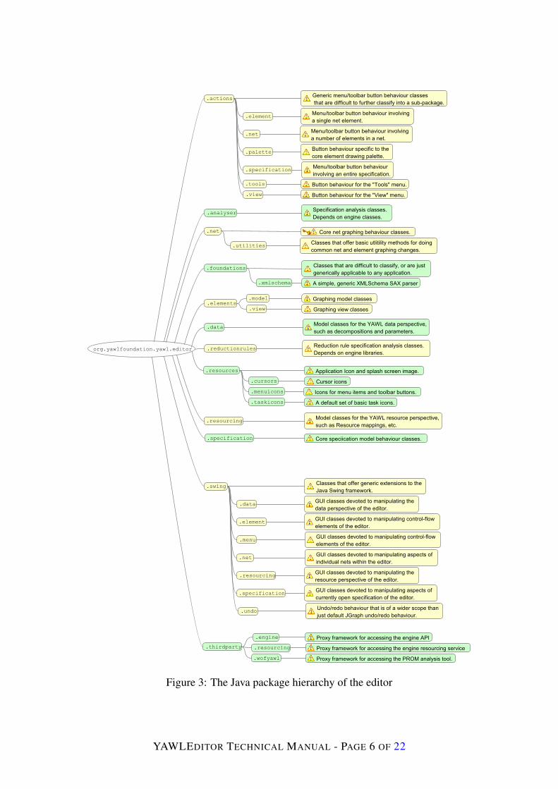
Figure 3: The Java package hierarchy of the editor
YAWLEDITOR TECHNICAL MANUAL - PAGE 6 OF 22
o r g . y a w l f o u n d a t i o n . y a w l . e d i t o r . e l e m e n t s . m o d e l
o r g . j g r a p h . g r a p h
V e r t e x C o n t a i n e rV e r t e x L a b e l0 . . 1 1
D e f a u l t G r a p h C e l l
< < I n t e r f a c e > >
Y A W L C e l l
Y A W L V e r t e x Y A W L F l o w R e l a t i o n
D e f a u l t E d g e
Y A W L P o r t
D e f a u l t P o r t
D e c o r a t o r P o r t
Y A W L C o n d i t i o n
I n p u t C o n d i t i o n C o n d i t i o n O u t p u t C o n d i t i o n
D e c o r a t o r
S p l i t D e c o r a t o r J o i n D e c o r a t o r
1
0 . . 1
0 . . 1 1
5
1
0 . . 1
1
Y A W L T a s k
C o m p o s i t e T a s k A t o m i c T a s k
M u l t i p l e A t o m i c T a s kM u l t i p l e C o m p o s i t e T a s k
< < I n t e r f a c e > >
Y A W L C o m p o s i t e T a s k
< < I n t e r f a c e > >
Y A W L M u l t i p l e I n s t a n c e T a s k
3 . . 4
1
< < I n t e r f a c e > >
P o r t< < I n t e r f a c e > >
E d g e< < I n t e r f a c e > >
G r a p h C e l l
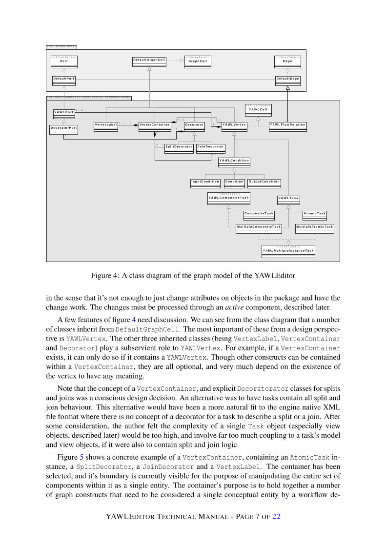
Figure 4: A class diagram of the graph model of the YAWLEditor
in the sense that it’s not enough to just change attributes on objects in the package and have thechange work. The changes must be processed through an active component, described later.
A few features of figure 4 need discussion. We can see from the class diagram that a numberof classes inherit from DefaultGraphCell. The most important of these from a design perspec-tive is YAWLVertex. The other three inherited classes (being VertexLabel, VertexContainerand Decorator) play a subservient role to YAWLVertex. For example, if a VertexContainerexists, it can only do so if it contains a YAWLVertex. Though other constructs can be containedwithin a VertexContainer, they are all optional, and very much depend on the existence ofthe vertex to have any meaning.
Note that the concept of a VertexContainer, and explicit Decoratorator classes for splitsand joins was a conscious design decision. An alternative was to have tasks contain all split andjoin behaviour. This alternative would have been a more natural fit to the engine native XMLfile format where there is no concept of a decorator for a task to describe a split or a join. Aftersome consideration, the author felt the complexity of a single Task object (especially viewobjects, described later) would be too high, and involve far too much coupling to a task’s modeland view objects, if it were also to contain split and join logic.
Figure 5 shows a concrete example of a VertexContainer, containing an AtomicTask in-stance, a SplitDecorator, a JoinDecorator and a VertexLabel. The container has beenselected, and it’s boundary is currently visible for the purpose of manipulating the entire set ofcomponents within it as a single entity. The container’s purpose is to hold together a numberof graph constructs that need to be considered a single conceptual entity by a workflow de-
YAWLEDITOR TECHNICAL MANUAL - PAGE 7 OF 22

signer. Again, the author stresses that without the AtomicTask, there is no purpose to the otherconstructs that have been bound to it.
Figure 5: A concrete example of a VertexContainer binding task elements together.
Note also from figure 4, that there are a number of ports bound to certain key objects. Adesign decision was made to have a number of ports per net graph element, to be positionedalong an appropriate boundary of the graph element. The alternative considered was to havea single port at the centre of a node where all flows for that node could be connected, whichis more in keeping with packages such as Microsoft Visio. This Visio-style approach has alsobeen occasionally asked for in the past. Two insights led the the approach constructed:
• Splits and joins in YAWL overlap in their representative icons. A single port would allowa great deal of ambiguity over the kind of split or join that a task had (a flow could bedrawn running into an or-split, for example, which is also drawn the same way as anor-join). The author decided that to force only outgoing flow from splits, and incomingflows to joins, thus removing a degree of possible confusion around splits and joins.
• The mechanics for having a flow connect to the center of a node, but only drawn to itsedge breaks down when a task has a split and a join on adjacent edges. The bounding-boxof the entire task element set, including the split and join has a small square of whitespacebetween the two decorators, and flows would run only to the edge of this whitespace. Theresult would be a flow that seems to stop short of the task to which it’s connected.
Conditions and tasks both have sub-trees of inheritance from YAWLVertex and each en-code their own specific required model constraints. Note that the class hierarchy depicted infigure 4 introduces a set of methods that allows a particular class to answer questions aboutwhat may validly be done with it, meaning that as far as possible, rules are localised to theclass involving them. For example, a standard Condition allows both incoming and outgo-ing flows. If you were to ask an InputCondition, however, if it allowed incoming flows, itwould answer in the negative. The reader is directed to the interface YAWLCell for a set of basicmethods that all tasks, conditions and flow relations must implement. Further interfaces (seeYAWLCompositeTask for example), deeper in the hierarchy introduce more specialised methodsto enforce requirements particular to certain workflow elements.
The corresponding views of the model objects described above can also be viewed as pas-sive. They simply draw on the screen a representation of their corresponding model objectequivalents. Figure 6 is a class diagram mapping key model classes from figure 4 to theview classes responsible for their rendering. The view classes required reside in the packageorg.yawlfoundation.yawl.editor.elements.view.
YAWLEDITOR TECHNICAL MANUAL - PAGE 8 OF 22
o r g . y a w l f o u n d a t i o n . e d i t o r . e l e m e n t s . v i e w
o r g . y a w l f o u n d a t i o n . e d i t o r . e l e m e n t s . m o d e l
A t o m i c T a s k
M u l t i p l e A t o m i c T a s k
C o m p o s i t e T a s k
M u l t i p l e C o m p o s i t e T a s k
I n p u t C o n d i t i o n
O u t p u t C o n d i t i o n
C o n d i t i o n
D e c o r a t o r
V e r t e x C o n t a i n e r Y A W L P o r tY A W L F l o w R e l a t i o n
o r g . j g r a p h . g r a p h
E d g e V i e w V e r t e x V i e w
1
1
1
1
A t o m i c T a s k V i e w
M u l t i p l e A t o m i c T a s k V i e w
C o m p o s i t e T a s k V i e w
M u l t i p l e C o m p o s i t e T a s k V i e w
I n p u t C o n d i t i o n V i e w
O u t p u t C o n d i t i o n V i e w
C o n d i t i o n V i e w
D e c o r a t o r V i e w
P o r t V i e w
1
1
1
1
1
1
1
1
1
1
1
1
1
1
1
1
1
1
o r g . y a w l f o u n d a t i o n . e d i t o r . n e t
N e t G r a p h N e t C e l l V i e w F a c t o r y
D e f a u l t G r a p h L a y o u t C a c h e
s u p p l i e s v i e w s f o r
1
1
u s e s t o r e n d e r o v e r a l l v i e w
1
1
* *
*
*
*
*
c r e a t e s
1
**
* *
c r e a t e s
1
*
*
*
*
*
*
*
*
*
*
c r e a t e s a m a t c h i n g v i e w f o r m o d e l o b j e c t1
*
Figure 6: A class diagram of how model objects are associated with their views
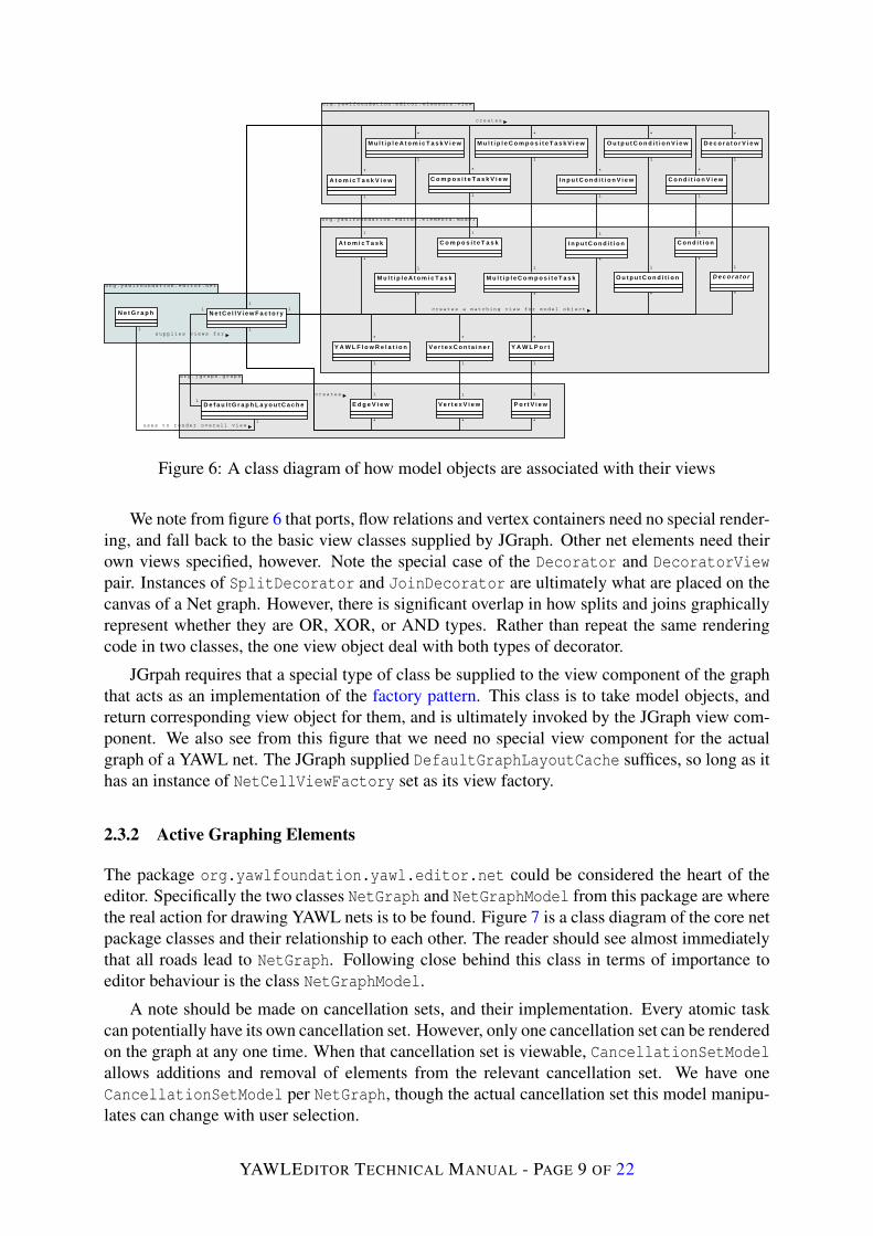
We note from figure 6 that ports, flow relations and vertex containers need no special render-ing, and fall back to the basic view classes supplied by JGraph. Other net elements need theirown views specified, however. Note the special case of the Decorator and DecoratorViewpair. Instances of SplitDecorator and JoinDecorator are ultimately what are placed on thecanvas of a Net graph. However, there is significant overlap in how splits and joins graphicallyrepresent whether they are OR, XOR, or AND types. Rather than repeat the same renderingcode in two classes, the one view object deal with both types of decorator.
JGrpah requires that a special type of class be supplied to the view component of the graphthat acts as an implementation of the factory pattern. This class is to take model objects, andreturn corresponding view object for them, and is ultimately invoked by the JGraph view com-ponent. We also see from this figure that we need no special view component for the actualgraph of a YAWL net. The JGraph supplied DefaultGraphLayoutCache suffices, so long as ithas an instance of NetCellViewFactory set as its view factory.
2.3.2 Active Graphing Elements
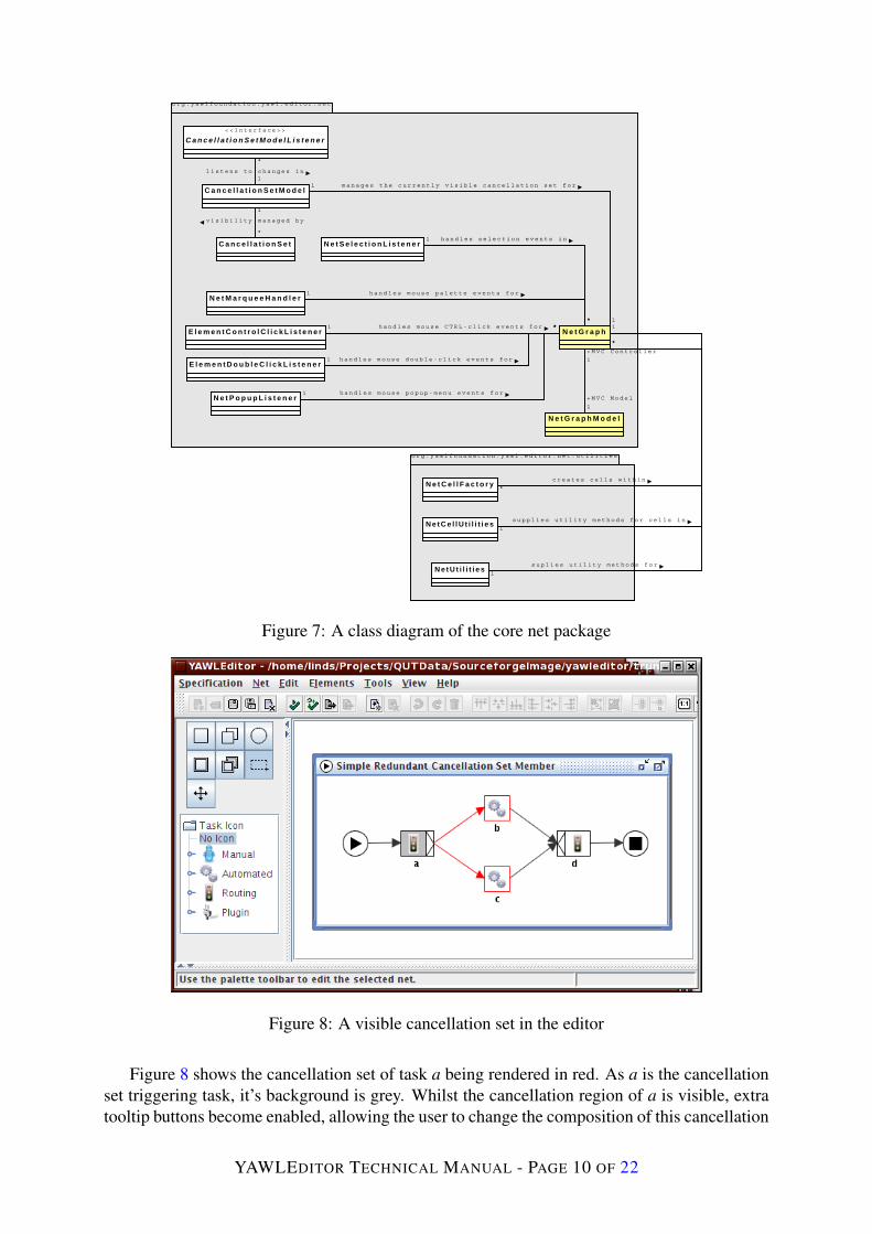
The package org.yawlfoundation.yawl.editor.net could be considered the heart of theeditor. Specifically the two classes NetGraph and NetGraphModel from this package are wherethe real action for drawing YAWL nets is to be found. Figure 7 is a class diagram of the core netpackage classes and their relationship to each other. The reader should see almost immediatelythat all roads lead to NetGraph. Following close behind this class in terms of importance toeditor behaviour is the class NetGraphModel.
A note should be made on cancellation sets, and their implementation. Every atomic taskcan potentially have its own cancellation set. However, only one cancellation set can be renderedon the graph at any one time. When that cancellation set is viewable, CancellationSetModelallows additions and removal of elements from the relevant cancellation set. We have oneCancellationSetModel per NetGraph, though the actual cancellation set this model manipu-lates can change with user selection.
YAWLEDITOR TECHNICAL MANUAL - PAGE 9 OF 22
o r g . y a w l f o u n d a t i o n . y a w l . e d i t o r . n e t
C a n c e l l a t i o n S e t
C a n c e l l a t i o n S e t M o d e l
< < I n t e r f a c e > >
C a n c e l l a t i o n S e t M o d e l L i s t e n e r
l i s t e n s t o c h a n g e s i n
*
1
v i s i b i l i t y m a n a g e d b y
*
1
N e t G r a p h
N e t G r a p h M o d e l
E l e m e n t C o n t r o l C l i c k L i s t e n e r
E l e m e n t D o u b l e C l i c k L i s t e n e r
N e t P o p u p L i s t e n e r
N e t M a r q u e e H a n d l e r
N e t S e l e c t i o n L i s t e n e r
o r g . y a w l f o u n d a t i o n . y a w l . e d i t o r . n e t . u t i l i t i e s
N e t C e l l F a c t o r y
N e t C e l l U t i l i t i e s
N e t U t i l i t i e s
h a n d l e s m o u s e p a l e t t e e v e n t s f o r1
*h a n d l e s m o u s e C T R L - c l i c k e v e n t s f o r1 *
h a n d l e s m o u s e d o u b l e - c l i c k e v e n t s f o r1
*
h a n d l e s m o u s e p o p u p - m e n u e v e n t s f o r1
*
c r e a t e s c e l l s w i t h i n
1
*
+ M V C C o n t r o l l e r
1
+ M V C M o d e l
1
s u p p l i e s u t i l i t y m e t h o d s f o r c e l l s i n
*
1
s u p l i e s u t i l i t y m e t h o d s f o r
*
1
h a n d l e s s e l e c t i o n e v e n t s i n1
*
m a n a g e s t h e c u r r e n t l y v i s i b l e c a n c e l l a t i o n s e t f o r1
1
Figure 7: A class diagram of the core net package
Figure 8: A visible cancellation set in the editor
Figure 8 shows the cancellation set of task a being rendered in red. As a is the cancellationset triggering task, it’s background is grey. Whilst the cancellation region of a is visible, extratooltip buttons become enabled, allowing the user to change the composition of this cancellation
YAWLEDITOR TECHNICAL MANUAL - PAGE 10 OF 22

set. This is a deliberate design choice that varies somewhat from the “lasso” approach describedin the YAWL research publications. The lasso concept proved be difficult to implement, espe-cially when some tasks in a rectangular region of a lasso may not be part of the cancellationset.
There are also a number of classes that register as mouse and keyboard listeners withNetGraph to handle various functionality triggered by these forms of input. Most of theseclasses are rather trivial, and quickly understandable with a quick perusal of the actual code.One, however, is rather complex, and deserves further discussion.
This class is NetMarqueeHandler, and is responsible for dealing with basic drawing on thegraph, taking into account a number of factors, such as the currently selected palette button,and the type of element the mouse was hovering over when a user began using the mouse onthe graph. The key behaviour of this class is to recognise and react to mouse events for placingtasks and conditions on the graph, to allow flows to be drawn between valid net elements, andto allow for the selection of a number of elements for further processing.
Earlier versions of the editor required a “flow palette button” that had be selected to allowflows to be drawn between elements. Several users mentioned that they wished to draw flowswithout having to select the palette button, however. Texts on UI design2 also suggest thatremoving modal behaviour, such as explicitly requiring a flow palette button to be depressedfor drawing a flow, be removed where possible. Thus, NetMarqueeHandler underwent anoverhaul, and implemented a state transition machine that allowed the user to draw flows iftheir mouse was over a valid port, to drag an element if over the element, or drop a new elementonto the graph canvas if there is nothing under the mouse. The state transition diagram usedto initially design the desired change in marquee behaviour is shown in figure 9. It is suppledhere in the hopes of allowing a quick understanding of the state transition machine built intoNetMarqueeHandler.
Over Vertex[overVertex]
mouseMoved()
Over Outgoing Port[overOutgoingPort]
mouseMoved()
Dragging VertexmousePressed()
Idle
[overNothing]
mouseMoved()
[overNothing]
mouseMoved()
Drawing FlowmousePressed()
mouseDragged()
mouseDragged()
mouseReleased()
mouseReleased()
Figure 9: A state transition diagram for NetMarqueeHandler
2See “The Humane Interface” by Jef Raskin for one of the better explanation on why modal UI behaviour is tobe avoided where possible.
YAWLEDITOR TECHNICAL MANUAL - PAGE 11 OF 22
2.4 Build Environment
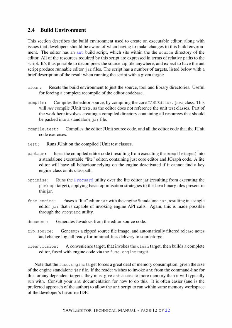
This section describes the build environment used to create an executable editor, along withissues that developers should be aware of when having to make changes to this build environ-ment. The editor has an ant build script, which sits within the the source directory of theeditor. All of the resources required by this script are expressed in terms of relative paths to thescript. It’s thus possible to decompress the source zip file anywhere, and expect to have the antscript produce runnable editor jar files. The script has a number of targets, listed below with abrief description of the result when running the script with a given target:
clean: Resets the build environment to just the source, tool and library directories. Usefulfor forcing a complete recompile of the editor codebase.
compile: Compiles the editor source, by compiling the core YAWLEditor.java class. Thiswill not compile JUnit tests, as the editor does not reference the unit test classes. Part ofthe work here involves creating a compiled directory containing all resources that shouldbe packed into a standalone jar file.
compile.test: Compiles the editor JUnit source code, and all the editor code that the JUnitcode exercises.
test: Runs JUnit on the compiled JUnit test classes.
package: fuses the compiled editor code ( resulting from executing the compile target) intoa standalone executable “lite” editor, containing just core editor and JGraph code. A liteeditor will have all behaviour relying on the engine deactivated if it cannot find a keyengine class on its classpath.
optimise: Runs the Proguard utility over the lite editor jar (resulting from executing thepackage target), applying basic optimisation strategies to the Java binary files present inthis jar.
fuse.engine: Fuses a “lite” editor jar with the engine Standalone jar, resulting in a singleeditor jar that is capable of invoking engine API calls. Again, this is made possiblethrough the Proguard utility.
document: Generates Javadocs from the editor source code.
zip.source: Generates a zipped source file image, and automatically filtered release notesand change log, all ready for minimal-fuss delivery to sourceforge.
clean.fusion: A convenience target, that invokes the clean target, then builds a completeeditor, fused with engine code via the fuse.engine target.
Note that the fuse.engine target forces a great deal of memory consumption, given the sizeof the engine standalone jar file. If the reader wishes to invoke ant from the command-line forthis, or any dependent targets, they must give ant access to more memory than it will typicallyrun with. Consult your ant documentation for how to do this. It is often easier (and is thepreferred approach of the author) to allow the ant script to run within same memory workspaceof the developer’s favourite IDE.
YAWLEDITOR TECHNICAL MANUAL - PAGE 12 OF 22

Note also, the existence of the file build.properties residing in the same directory as theant build script. The build script uses this properties file to identify dependencies the editor hason other technologies. The properties file is also used to apply filter across the editor sourcecode, replacing placeholder text with actual text spread throughout the editor text for the currentbuild (such a release numbers, etc.).
There are two sibling directories to the source directory that are important for generatingan executable editor. These directories are libs and tools, currently containing the standaloneengine jar, and the Proguard utility respectively. As alluded to earlier, Proguard is used to fuseeditor and engine code to create a single standalone editor jar. This utility is not trivial, how-ever, and can cause a great deal of time to be consumed if you want to get it to do much morethan just sticking jar files together. The editor is being optimised via Proguard currently, butattempts to apply similar processing to the standalone engine jar have resulted in missing/bro-ken code in the output result. This was not always the case, but recent releases of the engineseem to be too much for Proguard handle successfully.
When it comes to actually building the editor, the author will typically chooses the packagetarget, which only takes a few seconds to produce a lite editor. The engine standalone jar isleft in the same directory as the freshly minted lite editor to allow the editor access to enginefunctionality. It is only when someone needs a complete standalone editor, or the author ispreparing for an official release of the editor that he will run the fuse.engine target, whichcan take several minutes to complete. Build file deliverables, such as jar files or source zipfiles, are all placed in a distribution directory, created as a sibling to the source directory.
The original rationale for a “lite” editor as well as the full editor stems from the author’slong-held belief that the editor and engine should remain as decoupled as possible. A liteeditor allows the author to quickly ascertain whether the editor will function as intended, evenwithout access to the engine. More will be said on coupling between the editor and engine inlater sections. In recent releases, the lite editor has also started shipping with the automatedWindows installer, which ensures that the editor has access to the standalone engine jar, andreducing the overall installation file size to just what needs to be shipped.
3 Superstructure
This section describes superstructure of the editor, which uses features described in section 2 asthe necessary operational basis for the behaviour described here. The author names behaviour“superstructure”, because in a very real sense, this behaviour relies on the behaviour alreadydescribed in this earlier section.
This section is broken into a number of subsections. Section 3.1 deals with various aspectsto specification management. Section 3.2 describes the typical approach that has been taken tointerfacing with 3rd-party software. Section 3.3 briefly describes Swing undo/redo functionalityextensions that were needed above and beyond basic JGraph undo/redo behaviour. Section 3.4describes the general approach taken to JUnit testing of the editor.
3.1 Specification Management
Section 2.3 covered editor behaviour that involved manipulating a single net’s graph. A speci-fication is composed of several nets, however. This section describes key editor behaviour for
YAWLEDITOR TECHNICAL MANUAL - PAGE 13 OF 22

manipulating a specification. Note that the editor can currently edit only a single specificationat a time. This was a design decision taken early in the life of the editor in order to achieve ausable prototype as quickly as possible. Since then, the desire for editing several specificationshas been raised time and again. The main prohibiter has been time.
The author has put some effort into allowing several specifications to be edited at once, butmuch is yet to be done for this work to be considered complete. Typically, if the author hashad to revisit code assuming a single specification for some reason, he has tried to loosen theone-specification constraint at the same time. Currently most programming constructs aroundspecifications assume that only a single specification is being worked upon. A small amount ofspecification code has been loosened up to allow than one specification loaded into the editor.Most of the core model behaviour for specifications described here resides within the packageorg.yawlfoundation.yawl.editor.specification.
Figure 10 is a class diagram of the key classes in the specification package. Associationswith classes in related packages are shown where the author thought it appropriate.
o r g . y a w l f o u n d a t i o n . y a w l . e d i t o r . s p e c i f i c a t i o n
o r g . y a w l f o u n d a t i o n . y a w l . e d i t o r . t h i r d p a r t y . e n g i n e
S p e c i f i c a t i o n M o d e l
S p e c i f i c a t i o n F i l e M o d e l
A r c h i v i n g T h r e a d
S p e c i f i c a t i o n A r c h i v e H a n d l e r
Y A W L E n g i n e P r o x y
1
1 s u p p l i e s a d e v o t e d I / O t h r e a d f o r1
1
< < I n t e r f a c e > >
S p e c i f i c a t i o n F i l e M o d e l L i s t e n e r
l i s t e n s f o r k e y f i l e - b a s e d e v e n t s o f
*
1
h a n d l e s f i l e e v e n t s f o r
1
1 s a v e s a n d l o a d s
1
1
e n a b l e s e x p o r t , i m p o r t , v a l i d a t i o n a n d a n a l y s i s o f
1
1
< < I n t e r f a c e > >
S p e c i f i c a t i o n M o d e l L i s t e n e r
l i s t e n s f o r s t a t e c h a n g e s i n
*
1S p e c i f i c a t i o n U t i l i t i e s
p r o v i d e s u t i l i t i e s f o r
1
1
S p e c i f i c a t i o n U n d o M a n a g e r
m a n a g e s u n d o / r e d o g r a p h e v e n t s f o r
1
1
b l o c k s m u l t i p l e I / O a t t e m p t s v i a
1
1
S p e c i f i c a t i o n S e l e c t i o n L i s t e n e r< < I n t e r f a c e > >
S p e c i f i c a t i o n S e l e c t i o n S u b s c r i b e r
r e c e i v e s s e l e c t i o n e v e n t s o f i n t e r e s t f r o m
* 1
o r g . y a w l f o u n d a t i o n . y a w l . e d i t o r . n e t
N e t G r a p h
c o n t a i n s
1 +
1
N e t S e l e c t i o n L i s t e n e r
d e l e g a t e s s e l e c t i o n e v e n t p r o c e s s i n g t o1 +
1
r e c e i v e s s e l e c t i o n e v e n t s f r o m
1
1
Figure 10: A class diagram of the core specification package
3.1.1 State Management
The two core specification package classes SpecificationModel and SpecificationFileModeloperate as state transition machines that listeners can react to upon key state change events.
State transition in SpecificatioModel is rather trivial. There are two main states thatit toggles between, namely NO NETS EXIST and NETS EXIST. The first of these states happensonly briefly on a reset of a specification model, as a valid specification must always have at leasta root net. A number of events are also occasionally fired from this class, but are not states assuch, just event notifications that state listeners may also care to know about. These events areNO NET SELECTED, SOME NET SELECTED, and NET DETAIL CHANGED. Classes that implementthe SpecificationModelListener interface will be notified of these events, and react as they
YAWLEDITOR TECHNICAL MANUAL - PAGE 14 OF 22
deem most appropriate.
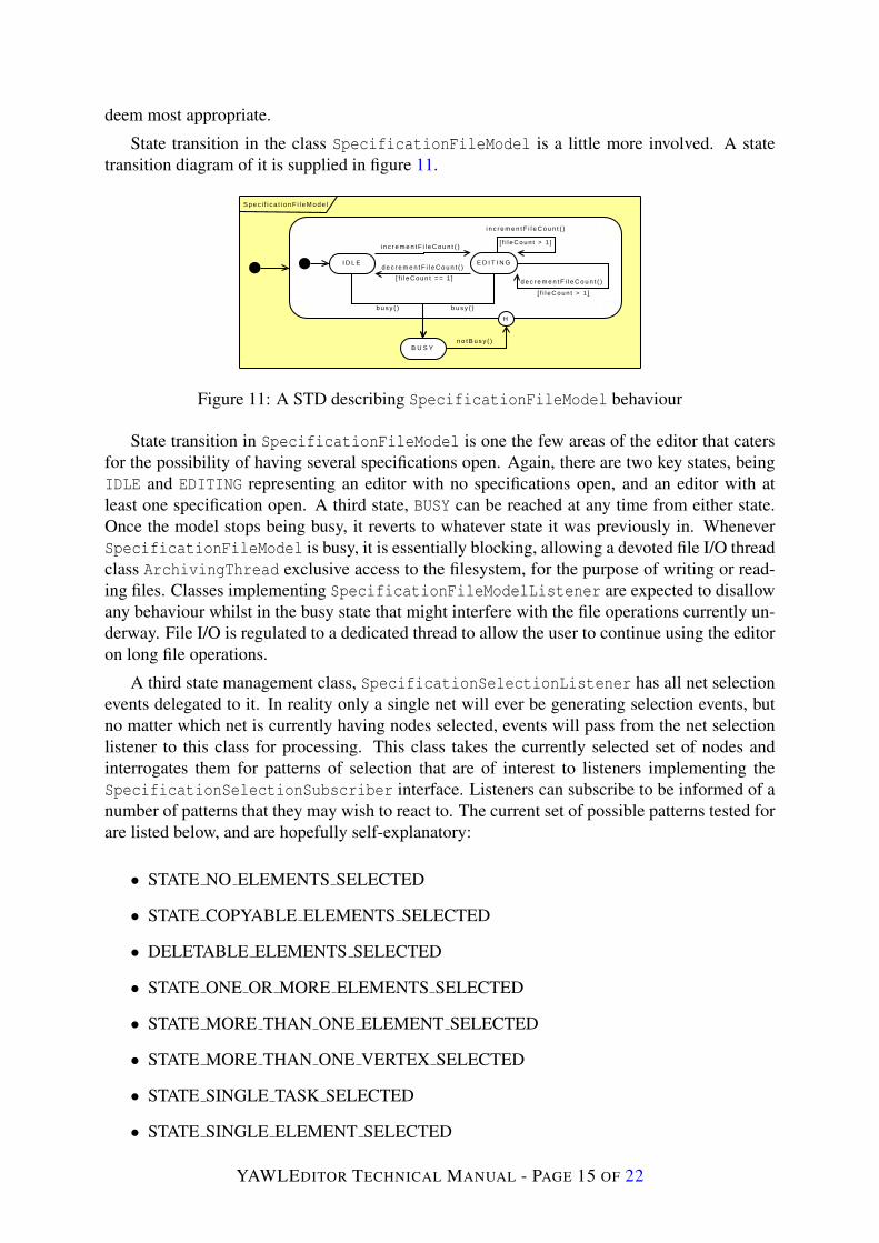
State transition in the class SpecificationFileModel is a little more involved. A statetransition diagram of it is supplied in figure 11.
S p e c i f i c a t i o n F i l e M o d e l
I D L E E D I T I N G
B U S Y
i n c r e m e n t F i l e C o u n t ( )[ f i l eCoun t > 1 ]
i n c r e m e n t F i l e C o u n t ( )
[ f i l eCoun t > 1 ]
d e c r e m e n t F i l e C o u n t ( )[ f i l e C o u n t = = 1 ]
d e c r e m e n t F i l e C o u n t ( )
b u s y ( ) b u s y ( )
H
n o t B u s y ( )
Figure 11: A STD describing SpecificationFileModel behaviour
State transition in SpecificationFileModel is one the few areas of the editor that catersfor the possibility of having several specifications open. Again, there are two key states, beingIDLE and EDITING representing an editor with no specifications open, and an editor with atleast one specification open. A third state, BUSY can be reached at any time from either state.Once the model stops being busy, it reverts to whatever state it was previously in. WheneverSpecificationFileModel is busy, it is essentially blocking, allowing a devoted file I/O threadclass ArchivingThread exclusive access to the filesystem, for the purpose of writing or read-ing files. Classes implementing SpecificationFileModelListener are expected to disallowany behaviour whilst in the busy state that might interfere with the file operations currently un-derway. File I/O is regulated to a dedicated thread to allow the user to continue using the editoron long file operations.
A third state management class, SpecificationSelectionListener has all net selectionevents delegated to it. In reality only a single net will ever be generating selection events, butno matter which net is currently having nodes selected, events will pass from the net selectionlistener to this class for processing. This class takes the currently selected set of nodes andinterrogates them for patterns of selection that are of interest to listeners implementing theSpecificationSelectionSubscriber interface. Listeners can subscribe to be informed of anumber of patterns that they may wish to react to. The current set of possible patterns tested forare listed below, and are hopefully self-explanatory:
• STATE NO ELEMENTS SELECTED
• STATE COPYABLE ELEMENTS SELECTED
• DELETABLE ELEMENTS SELECTED
• STATE ONE OR MORE ELEMENTS SELECTED
• STATE MORE THAN ONE ELEMENT SELECTED
• STATE MORE THAN ONE VERTEX SELECTED
• STATE SINGLE TASK SELECTED
• STATE SINGLE ELEMENT SELECTED
YAWLEDITOR TECHNICAL MANUAL - PAGE 15 OF 22

Behaviour across the various aspects of the editor is only valid when one more more of theabove patterns of selection are true. Such behaviour will implement the previously mentionedinterface and subscribe for patterns where that behaviour can be applied. For example, inputconditions and output conditions cannot be deleted or copied from a net. If a selection in a netselects only an input condition, the copy menu item will know that it has nothing to copy, andstay disabled until such time as a selection event includes net elements that can be copied.
3.1.2 Saving and Loading
The class SpecificationArchiveHandler is responsible for saving and loading YAWLEditorsave files. These save files are, quite literally, an XML serialization of specification modelobjects that has been compressed using the popular Winzip compression algorithm. It is thuspossible to open an editor save file with Winzip or some other compatible compression utilityand interrogate the XML representing the sate of model objects in the editor at save-time.
The author first settled on this method of just XML serialization for state storage and re-trieval as it was the recommended approach suggested by JGraph authors for saving and load-ing a graph. Unfortunately, even small graphs were taking an unacceptably long time to saveand load, and file sizes were disturbingly large for such small graphs. The author found thatcompressing the XML in memory before writing, and reading a smaller file size tended to workbetter for both file size and save/load times.
Part of the problem here is that JGraph is designed to be a generic graphing tool. As aconsequence, every element of a graph comes with a very large number of attributes to allowJGraph the flexibility to be applied in radically different graphing scenarios. The alternativeconsidered, and quickly rejected for the amount of programming effort involved in what wasstill considered a prototype, would to be parse the graph elements and write a save-file format(again, probably XML) that encoded just the bare minimum graphing information needed.
The lion’s share of each save-file is an XML encoding of the state of each NetGraphModelpresent in the specification. Each NetGraphModel in turn, contains model elements from theclasses depicted in figure 4. However, there is more state to a specification than just a setof NetGraphModel instances. To capture state that must be saved and loaded, wider than thescope of NetGraphModel, two more serializable classes are needed. ArchivableNetStateand ArcivableSpecificationState collect together the remaining savable state for nets andspecifications respectively. They reside in org.yawlfoundation.yawl.editor.foundations.
All classes that are to be serialized as part of the editor save/load routine have evolved overtime to be more flexible in terms of adding new state. These classes now uniformly store at-tributes for their instance objects in a Java HashMap called serializationProofAttributeMap.Note that without this approach to saving and loading object attributes, the addition of a newattribute to a class will break save-file backward compatibility, stopping the editor from suc-cessfully loading older specifications that do not have a newly introduced object attribute. Notealso that JGraph employs a similar technique for it’s core graphing elements.
Listing 2 shows example code to highlight the way in which state is expected to resideas attributes in these model objects. As they will ultimate by processed by the Java classesjava.beans.XMLEncoder and java.beans.XMLDecoder, all state to be saved and loaded needto conform to those parts of the Java Bean standard needed by these XML utilities. Specifically,the class needs a no-argument constructor, which will be invoked when the class is initiallyde-serialized, and a get()/set() method pair for each attribute that they wish to serialize.
YAWLEDITOR TECHNICAL MANUAL - PAGE 16 OF 22
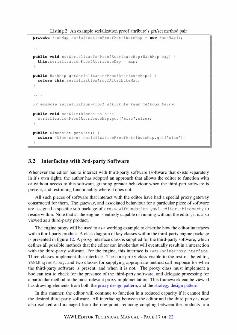
Listing 2: An example serialization proof attribute’s get/set method pairprivate HashMap serializationProofAttributeMap = new HashMap();
...
public void setSerializationProofAttributeMap(HashMap map) {this.serializationProofAttributeMap = map;
}
public HashMap getSerializationProofAttributeMap() {return this.serializationProofAttributeMap;
}
....
// example serialization-proof attribute bean methods below.
public void setSize(Dimension size) {serializationProofAttributeMap.put("size",size);
}
public Dimension getSize() {return (Dimension) serializationProofAttributeMap.get("size");
}
3.2 Interfacing with 3rd-party Software
Whenever the editor has to interact with third-party software (software that exists separatelyin it’s own right), the author has adopted an approach that allows the editor to function withor without access to this software, granting greater behaviour when the third-part software ispresent, and restricting functionality where it does not.
All such pieces of software that interact with the editor have had a special proxy gatewayconstructed for them. The gateway, and associated behaviour for a particular piece of softwareare assigned a specific sub-package of org.yawlfoundation.yawl.editor.thirdparty toreside within. Note that as the engine is entirely capable of running without the editor, it is alsoviewed as a third-party product.
The engine proxy will be used to as a working example to describe how the editor interfaceswith a third-party product. A class diagram of key classes within the third-party engine packageis presented in figure 12. A proxy interface class is supplied for the third-party software, whichdefines all possible methods that the editor can invoke that will eventually result in a interactionwith the third-party software. For the engine, this interface is YAWLEngineProxyInterface.Three classes implement this interface. The core proxy class visible to the rest of the editor,YAWLEngineProxy, and two classes for supplying appropriate method call response for whenthe third-party software is present, and when it is not. The proxy class must implement aboolean test to check for the presence of the third-party software, and delegate processing fora particular method to the most relevant proxy implementation. This framework can be viewedhas drawing elements from both the proxy design pattern, and the strategy design pattern.
In this manner, the editor will continue to function in a reduced capacity if it cannot findthe desired third-party software. All interfacing between the editor and the third party is nowalso isolated and managed from the one point, reducing coupling between the products to a
YAWLEDITOR TECHNICAL MANUAL - PAGE 17 OF 22
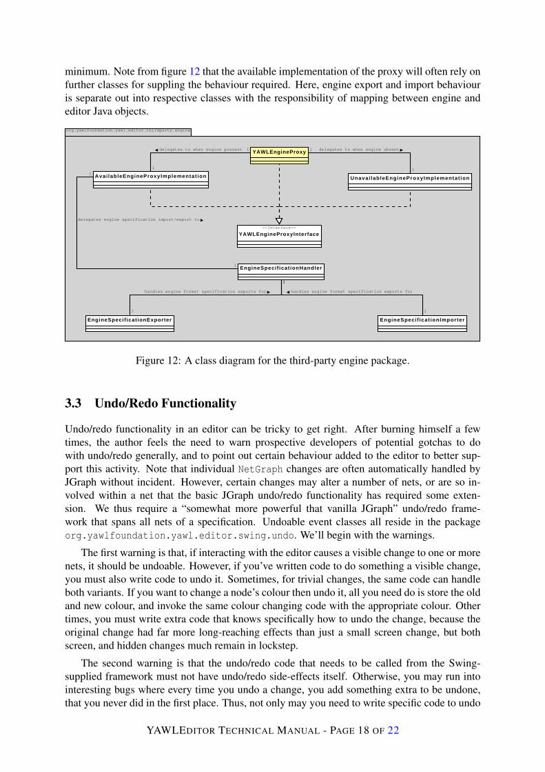
minimum. Note from figure 12 that the available implementation of the proxy will often rely onfurther classes for suppling the behaviour required. Here, engine export and import behaviouris separate out into respective classes with the responsibility of mapping between engine andeditor Java objects.
org.yawlfoundation.yawl.editor.thirdparty.engine
YAWLEngineProxy
<<Interface>>
YAWLEngineProxyInterface
Avai lableEngineProxyImplementat ion Unavai lableEngineProxyImplementat ion
delegates to when engine present 1
1
delegates to when engine absent1
1
EngineSpecif icationHandler
delegates engine specification import/export to
1
1
EngineSpecificationExporter EngineSpecif icationImporter
handles engine format specification exports for
1
1
handles engine format specification exports for
1
1
Figure 12: A class diagram for the third-party engine package.
3.3 Undo/Redo Functionality
Undo/redo functionality in an editor can be tricky to get right. After burning himself a fewtimes, the author feels the need to warn prospective developers of potential gotchas to dowith undo/redo generally, and to point out certain behaviour added to the editor to better sup-port this activity. Note that individual NetGraph changes are often automatically handled byJGraph without incident. However, certain changes may alter a number of nets, or are so in-volved within a net that the basic JGraph undo/redo functionality has required some exten-sion. We thus require a “somewhat more powerful that vanilla JGraph” undo/redo frame-work that spans all nets of a specification. Undoable event classes all reside in the packageorg.yawlfoundation.yawl.editor.swing.undo. We’ll begin with the warnings.
The first warning is that, if interacting with the editor causes a visible change to one or morenets, it should be undoable. However, if you’ve written code to do something a visible change,you must also write code to undo it. Sometimes, for trivial changes, the same code can handleboth variants. If you want to change a node’s colour then undo it, all you need do is store the oldand new colour, and invoke the same colour changing code with the appropriate colour. Othertimes, you must write extra code that knows specifically how to undo the change, because theoriginal change had far more long-reaching effects than just a small screen change, but bothscreen, and hidden changes much remain in lockstep.
The second warning is that the undo/redo code that needs to be called from the Swing-supplied framework must not have undo/redo side-effects itself. Otherwise, you may run intointeresting bugs where every time you undo a change, you add something extra to be undone,that you never did in the first place. Thus, not only may you need to write specific code to undo
YAWLEDITOR TECHNICAL MANUAL - PAGE 18 OF 22

a change, you may also occasionally have to write it in such a way as to offer two variants.One with undo/redo side-effects, and one without. Listing 3 shows an editor class that requiresdifferent code for the undo and redo, that must must also be side-effect free.
Listing 3: Example undoable editor classpublic class UndoableNetAddition extends AbstractUndoableEdit {
private static final long serialVersionUID = 1L;private NetGraphModel addedNet;
public UndoableNetAddition(NetGraphModel addedNet) {this.addedNet = addedNet;
}
public void redo() {SpecificationModel.getInstance().addNetNotUndoable(addedNet);addedNet.getGraph().getFrame().setVisible(true);
}
public void undo() {addedNet.getGraph().getFrame().setVisible(false);SpecificationModel.getInstance(). removeNetNotUndoable(addedNet);
}}
Figure 13 is a class diagram, focusing on the undoable edit presented in listing 3. It showshow all NetGraph instances pass their undoable events to SpecificationUndoManager, whichis capable of applying changes across several nets if needs be. It also points points out thatSpecificationModel creates a new net, and passes a specification-level undoable event forit’s creation to the undo manager. The event code presented knows to invoke methods onSpecificationModel with no undo/redo side-effects for redoing or undoing the addition ofa net to a specification.
org.yawlfoundation.yawl.editor.net
NetGraph
org.yawlfoundation.yawl.editor.specification
Specif icat ionUndoManager manages undo/redo events for1 *
org.yawlfoundation.yawl.editor.swing.undo
UndoableNetAddit ion
Specif icationModel
adds new
1
*
registers specification-wide undo-events with1
1
is registered with1
*
generates and registers
1
*
Figure 13: A class diagram undo/redo management of a specification.
The class SpecificationUndoManager has also been enhanced from a typical JGraph undo
YAWLEDITOR TECHNICAL MANUAL - PAGE 19 OF 22
manager so that the programmer can:
• Briefly refuse to record undoable events. This is useful for situations where we wishto make a visible change that is controlled by a mechanism other than undo/redo. Anexample is the toggling of a visible cancellation set. Whether the set is visible or not iscontrolled by a popup menu-item for a task, and should not be reversed or re-applied viatypical changes, as there is no “real” change happening to the specification here, just avisualisation to highlight aspects of existing state.
• Start and stop compounding edits. Sometimes a large change is composed of a numberof small changes that by default, JGraph would make all individual undoable events.Convenience methods are supplied here to make it easy to combine a number of edits intoa single edit. An example of where this occurs is in NetGraph, where re-labeling a taskis handled by deleting the old VertexLabel attached to a task, creating a new one, andre-balancing other elements in the task’s VertexContainer as appropriate.
3.4 Unit Testing Classes
A small number of JUnit test classes have been written for the editor. Code coverage is notsignificant, given the limited time, and the general difficulty that we always encounter withattempting to apply unit-tests to a predominately GUI codebases. What unit tests there aretypically lie on the border-regions of the interface between the editor and engine, as this hastraditionally been where hard-to-solve compatibility issues have arisen.
The key editor JUnit class is org.yawlfoundation.yawl.editor.TestYAWLEditor.java.This class acts to bootstrap other JUnit classes throughout the editor. Note that the author hasfollowed a convention for JUnit test classes that the reader should be aware of. A JUnit testclass limits it’s focus to a single editor class. It takes the name of the class it tests, and prependsthe text Test to identify the class it tests. Only JUnit classes can start with Test. A JUnit testclass also resides in the same package as the class it tests. As described earlier, the ant buildscript ensures that test classes are not shipped with the final editor, and enables a way of run-ning the JUnit tests outside of an IDE. The build script assumes the above convention in orderto correctly identify the test classes.
The class TestSpecificationEngineHandler, sitting in thirdparty.engine, is oftenpivotal to the continued assurance that the engine and editor interact as intended. This classprogramatically builds a number of specifications, some valid, some deliberately flawed, andasks the available engine-side code to confirm whether the specification is flawed or not.
4 Future Considerations
This final section of the manual lists a number of issues that have been raised from time to timein the past, but has not yet been addressed to the author’s satisfaction in the editor. The authorfeels that eventually, a better solution to existing behaviour mentioned in each subsection musteventually be tackled to finally free the editor of it’s prototype legacy. A common inhibitor forthese items is time. Most of the items listed represent a significant investment in time, and insome cases, with no visible change the the editor’s behaviour to show for the effort.
YAWLEDITOR TECHNICAL MANUAL - PAGE 20 OF 22
4.1 Saving and Loading
The editor has long been criticised for having a different file format to the engine for its spec-ifications. The author still holds to the belief that because the engine has no need for graphinginformation, it should not be forced to accept specifications that describe how a graph repre-sentation of a workflow is to be laid out (consider automated conversion of a process definitionfrom another language to YAWL that has a completely alien graphing approach, but whosefundamental scheduling can be expressed easily by YAWL).
The most appealing idea to date is one where the engine specification allows an optionalsection (separate from the core executable description) that describes graph layout. However,there are still subtle issues to be resolved before naively believing that all we need do is ex-pand the engine specification for graphing. The reader is urged to carefully study the classEngineSpecificationExporter for a number of surprises between how a specification isgraphed, and how it is encoded as engine XML.
A number of examples exist where the editor has had to explicitly add extra engine con-structs to allow the engine to execute a specification correctly, but that has no place in a graphrepresentation of the specification. An example is that the editor generate and insert conditionsthat are implicitly inferred on flows between two tasks whenever such a flow exists in a task’scancellation set. This explicit condition should never be drawn in the editor, however.
The greatest impediment to implementing this idea is simply time. An abstraction of netgraphing must be invented for storing in an engine specification file. Saving editor state mustthen parse every element in the graph and build the relevant XML to describe this abstraction.Similarly for loading a specification, where the abstraction must result in concrete graphingelements. This is not a trivial piece of work, despite optimistic assurances expressed to thecontrary.
4.2 Engine and Editor Coupling
Currently, coupling between the engine and editor is still higher than the author would like. Inorder to validate a specification, the editor builds a set of engine object from the editor model,turns this into engine XML, and asks the engine validation method to supply feedback on theengine XML. All of these activities rely on calls directly into core engine model objects. Thishas allowed a very rapid construction of an editor that can export and validate engine XML, butthe necessary cost is a very tight binding between the editor model and engine model.
The author has long dreamed of a time when an “official” engine XML definition is pub-lished that represents the accepted way of encoding YAWL in XML. With such a definition inplace, the ideal would be to have the editor not rely on engine objects for generating engineXML, but to generate engine compatible XML without the need to call engine library. Thiswould reduce coupling to the engine immensely, allowing a cleaner separation between the twocomponents than is currently possible.
4.3 Data Perspective Complexity
The data perspective of YAWL is complex, and requires deep XMLSchema and XQuery knowl-edge to successfully wield. It is often cited by users as the hardest part of YAWL to understand.The editor currently exposes all of the complexity here to users of the editor, simply because
YAWLEDITOR TECHNICAL MANUAL - PAGE 21 OF 22
abstraction to make it easier to wield the data perspective represents a significant investment intime. Searches, for example, for freeware editors to help construct valid XQuery expressionsdo not exist at the time of writing this document.
Even valid combinations of scope for passing data from a net to a task and back again is nottrivial. The reader is directed to DataVariableSet in org.yawlfoundation.yawl.editor.datafor a decision table describing valid scope combinations.
The common idea put forward for managing data perspective complexity is better editorsupport for the full complexity of the data perspective. Another option that the author hasrecently come to prefer, is revisiting the data perspective to simplify it. For example, convertingvalues as they pass from the net to the task could be removed, and replaced with a simplerapproach where the value passes from net to task unchanged. Any changes needed on the dataneeded is then forced to the task level, which is outside the scope of the engine. A simplifieddata perspective in the engine will result in simplified definition of that perspective in the editor.
4.4 Plugin Framework
Since version 1.5 of the editor, a simple plugin framework has been introduced. At the momentthis framework is primitive, but it has the potential to become a potent extension to the editor.As at version 2.0 of the editor, the plugin framework supports only task icons, and property filesthat describe extended attributes to be attached to task data variables and decompositions. Theauthor sees the plugin framework growing in the short to medium term in at least the followingtwo ways:
• As a mechanism to allow for a library of commonly used decompositions for a particularorganisation.
• In a similar vein, to allow a library of common resourcing specifications to be quicklyattached to a particular task. For instance, perhaps an organisation typically automati-cally allocates work to it’s users via the roles they play in a round-robin fashion, startingthe workitem immediately upon allocation. Such a resourcing decision could be pre-generated and available through the organizations plugin mechanism for quickly attachingto typical tasks in their workflows.
No doubt more behaviour will become candidates for plugin consideration if it represents atypical tightening of generic behavior to fast-track an organizations typical use of the editor.
YAWLEDITOR TECHNICAL MANUAL - PAGE 22 OF 22