Embed Size (px)
Citation preview
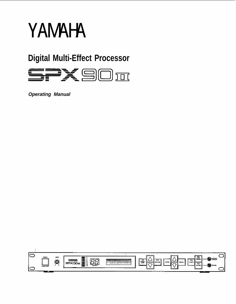
YAMAHADigital Multi-Effect Processor
Operating Manual
/
INTRODUCTION
Congratulations on your purchase of a Yamaha SPX90II Digital Multi-Effect Processor. The SPX90II is an amalgam of advanced acousticalresearch and digital technology designed to provide musicians and homerecording enthusiasts with a wide range of exciting effects.The SPX90II Digital Multi-Effect Processor utilizes highly refined LSI(Large Scale Integration) technology to create natural reverberation. Notonly is its assortment of 30 preset effects comprehensive enough to suitmost studio and performance applications, the SPX90II also allows youto create up to 60 additional effects and store them for instant recall.Your SPX90II can create effects far beyond mere reverberation, thoughthat in itself is of a truly superior quality. A variety of echo, delay, andspecial effects — each with comprehensive parameter adjustments — can beaccessed at the touch of a switch. And as the SPX90II is MIDI-compatible,it can be programmed to apply separate reverberation effects to a varietyof MIDI-compatible instruments.Your SPX90II Digital Multi-Effect Processor will prove extremely usefulin a variety of applications: acoustic electric, PA, MIDI instrument, andhome recording systems. In order to take advantage of the vast potentialof this component, we urge you to study this manual before connectingthe SPX90II to your system.We at Yamaha thank you, and wish you years of enjoyment with yourSPX90II.
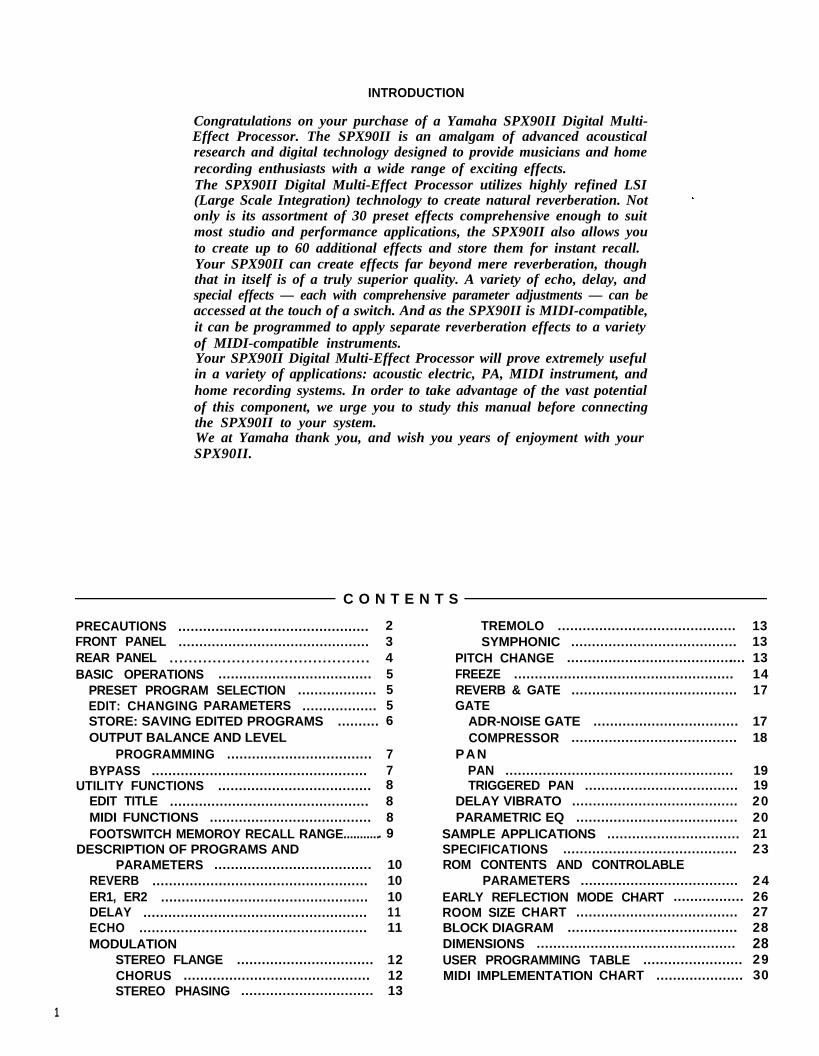
C O N T E N T S
PRECAUTIONS .............................................. 2FRONT PANEL .............................................. 3REAR PANEL ... . . . . . . . . . . . . . . . . . . . . . . . . . . . . . . . . . . . . . . . 4BASIC OPERATIONS ..................................... 5
PRESET PROGRAM SELECTION ................... 5EDIT: CHANGING PARAMETERS .................. 5STORE: SAVING EDITED PROGRAMS .......... 6OUTPUT BALANCE AND LEVEL
PROGRAMMING ................................... 7BYPASS .................................................... 7
UTILITY FUNCTIONS ..................................... 8EDIT TITLE ................................................ 8MIDI FUNCTIONS ....................................... 8FOOTSWITCH MEMOROY RECALL RANGE............ 9
DESCRIPTION OF PROGRAMS ANDPARAMETERS ...................................... 10
REVERB .................................................... 10ER1, ER2 .................................................. 10DELAY ...................................................... 11ECHO ....................................................... 11MODULATION
STEREO FLANGE ................................. 12CHORUS ............................................. 12STEREO PHASING ................................ 13
1
TREMOLO ........................................... 13SYMPHONIC ........................................ 13
PITCH CHANGE ............................................ 13FREEZE ..................................................... 14REVERB & GATE ........................................ 17GATE
ADR-NOISE GATE ................................... 17COMPRESSOR ........................................ 18
PANPAN ....................................................... 19TRIGGERED PAN ..................................... 19
DELAY VIBRATO ........................................ 20PARAMETRIC EQ ....................................... 20
SAMPLE APPLICATIONS ................................ 21SPECIFICATIONS .......................................... 23ROM CONTENTS AND CONTROLABLE
PARAMETERS ...................................... 24EARLY REFLECTION MODE CHART ................. 26ROOM SIZE CHART ....................................... 27BLOCK DIAGRAM ......................................... 28DIMENSIONS ................................................ 28USER PROGRAMMING TABLE ........................ 29MIDI IMPLEMENTATION CHART ..................... 30

PRECAUTIONSNOTE: It is vital to read this section before using your SPX90 II Digital Multi-Effect Processor. This unit utilizes
state-of-the-art digital technology which, although designed to provide years of trouble-free use, requiredcareful handling.
VOLTAGE RATINGSBe sure the AC supply in your area is appropriatefor your SPX90 II.U.S./Canadian Model: 110V — 120V, 50/60Hz.General Model: 220 — 240V, 50/60Hz.
ENVIRONMENTAL TEMPERATUREDo not expose the SPX90 II to excessive heat. Theoperating temperature range of this unit is between0 and 40 degrees centigrade (32 and 104 degreesFahrenheit).
EXTERNAL CLEANINGDo not clean the exterior of the SPX90 II withsolvents such as benzine or paint thinner. Dust, dirt,or fingermarks should simply be removed with asoft, dry cloth. Internal cleaning of the unit shouldonly be performed by a qualified technician.The LCD may not function properly under extremetemperature conditions. It will return to normal aftercooling down to within the proper temperaturerange.
BACKUP BATTERYTo ensure that User Programs are not lost when theSPX90II’s power is turned off, a built-in long-lifebattery acts as a backup. In normal use, this bat-tery lasts 5 years, but it is advisable to change thebattery before this time has elapsed. Contact yourlocal Yamaha dealer for details.NOTE: When you change the battery, the User Pro-
grams may be lost. As a safeguard, takenote of all parameters of your User Programsin the USER PROGRAMMING TABLE accom-panying this manual. The SPX90 II can thenbe reprogrammed once a new battery is in-stalled. The preset programs are permanent,and will not be affected by a change ofbattery.
ERROR MESSAGESWhen power is initially turned ON an automatic cir-cuit test program is executed to ensure properoperation. If an error is encountered, one of thefollowing error messages will be displayed:
E0 : ROM checksum error.E1: CPU RAM read/write error.E2 : External RAM read/write error.
Make a note of the error message and inform theservice personnel when the unit is to be serviced.
FCC CERTIFICATION (USA)
This equipment generates and uses radio frequency Reorient the receiving antenna.energy and if not installed and used properly, that is, in Relocate the computer with respect to the receiver.strict accordance with the manufacturer’s instructions, Move the computer away from the receiver.may cause interference to radio and television reception. Plug the computer into a different outlet so thatIt has been type tested and found to comply with the computer and receiver are on different branch circuits.limits for a Class B computing device in accordance with If necessary, the user should consult the dealer or anthe specifications in Subpart J of Part 15 of FCC Rules, experienced radio/television technician for additionalwhich are designed to provide reasonable protection suggestions. The user may find the following bookletagainst such interference in a residential installation. prepared by the Federal Communications CommissionHowever, there is no guarantee that interference will not helpful :occur in a particular installation. If this equipment does “ How to identify and Resolve Radio-TV interferencecause interference to radio or television reception, which Problems”.can be determined by turning the equipment-off and on, This booklet is available from the U.S. Governmentthe user is encouraged to try to correct the interference Printing Office, Washington, DC 20402, Stockby one or more of the following measures: No. 004-000-00345-4.
2

FRONT PANEL
Power ON/OFF SwitchWhen the power is turned ON, the program whichwas selected immediately before the power wasturned OFF will be re-selected. Due to the safetymuting circuit, no sound will be produced by theSPX90 II for a few seconds after the power isturned ON.Input Level Control (0 ~ 10)Regulates the level of the input signal. Set the IN-PUT LEVEL control while watching the INPUT LEVELmeter. The seven LED meter segments should notall be continuously on when an input signal is ap-plied, as this will result in input amplifier overloadand distortion. When the INPUT LEVEL control is setto “8” on the scale, the input/output gain is 1(unity). A setting of “10” increases gain by about10 dB.Input Level MeterThis easy-to-read LED level meter is a visual aid tosetting appropriate input levels. Generally, the bestinput level setting will produce continuous lightingof the lower green LED segments, while the upperred segments flash only occasionally.
Memory Number LEDThis LED display shows the number of the current-ly selected program. Memory numbers 1 through 30contain factory-preset effects (ROM). Memorynumbers 31 through 90 can be used to store editedversions of the preset effects (RAM).LCD Program and Parameter IndicatorThis high-contrast Liquid Crystal Display indicatesthe effect name and parameter data value.
Parameter KeySelects successive effect parameters. Pressing thiskey sequentially calls the programmable parameterswithin the currently selected effect program. Oncethe desired parameter has been selected, thePARAMETER INCREMENT/DECREMENT keys areused to change the value of that parameter, therebymodifying the effect. The parameters available foreach program are different: refer to the parameterchart on page 24.Parameter Increment/Decrement KeysThese keys are used to change the value of aselected parameter. Press the increment key (up ar-row) to increase the value, or the decrement key(down arrow) to decrease the value.Balance/Output Level KeyAdjusts proportion of effect signal to direct signal.Pressing this key alternately causes the currentbalance and output level values to be displayed onthe LCD. The Parameter Increment/Decrement keysare then used to adjust the displayed values.
Store KeyStores any edited preset effect in a selected RAMmemory position (31 ~ 90).Memory Increment/Decrement KeysThese keys select any desired memory number tocall a specific program or store an edited programin the user memory area. The selected memorynumber is shown on the MEMORY NUMBER display.When a new memory number is called, theMEMORY number display will flash until either theSTORE or RECALL function is activated.Recall KeyPress this key to recall the program that resides inthe selected memory number.Utility KeyMulti-purpose key accesses MIDI control functions,facilitates program title editing and sets footswitch
memory control range. See pages 8 and 9 for details.Foot Trigger KeyWhen this key is pressed and its LED is ON, thefootswitch connected to the Memory/Trigger jackfunctions as a foot trigger for the GATE and FREEZEprograms, rather than for memory selection.Bypass KeyWhen this key is pressed, the effect signal is shutoff and only the direct signal will be output. Directsignal level is affected by the INPUT LEVEL controlse t t ing .Memory/Trigger Footswitch JackFacilitates remote memory selection via optionalfootswitch. The range of memory locations to berecalled by the footswitch can be set with a Utilityprogram. When the foot trigger function (above) isON, the footswitch connected to this jack acts asa trigger footswitch rather than memory control. Useof a Yamaha FC5 Foot Controller is recommended.
Bypass Footswitch JackFacilitates foot control of the BYPASS functiondescribed above. A Yamaha FC-5 Foot Controller isrecommended.
3

REAR PANEL
Remote Control ConnectorPermits remote access to SPX90 II effect programs.The optional remote control unit, model RC7, per-mits direct access to programs 1 through 7 and 31through 37, while all other preset programs may beaccessed sequentially.
U.S. & Canadian models
MIDI THRU ConnectorRe-transmits MIDI data received at the MIDI IN con-nector to subsequent MIDI instruments.
MIDI IN ConnectorPermits SPX90 II effect programs to be automatical-ly selected via a MIDI signal. This connector mustbe connected to the MIDI OUT connector of thetransmitting MIDI instrument via a standard MIDIcable.
Output Level Selector ( —20 db + 4 db)Facilitates SPX90 II source/line level (sensitivity)match ing .
Output Jacks (L and R)These are standard mono 1/4” phone jacks whichdeliver the direct and effect signal to subsequentmixing or amplification equipment. Since theSPX90 II offers stereo output, we recommend thatthe output signal be fed in stereo to a stereo soundsystem in order to take full advantage of the superbstereo effects provided. Output impedance is 600o h m s .
USER LED ON— User programs —
USER LED OFF— Preset programs —
Input Level Selector ( — 20 dB, + 4 dB)Permits SPX90 II source/line level (sensitivity)m a t c h i n g .1. REV HALL 31. USER PROGRAM
2. REV 2 ROOM 32. USER PROGRAM
3. REV 2 VOCAL 33. USER PROGRAM
4. REV 4 PLATE 34. USER PROGRAM
5. EARLY REFLECTION 1 35. USER PROGRAM
6. EARLY REFLECTION 2 36. USER PROGRAM
7. DELAY L,R 37 USER PROGRAM
30. PARAMETRIC EQ(Programs 8 through 30)selected sequentially bypressing OTHERS/ -37-key)
Input jackThis standard unbalanced mono 1/4” phone jack ac-cepts the input signal to the SPX90 II. Input im-pedance is 10 k-ohms.
4

BASIC OPERATIONS
Before actually selecting or editing programs on your SPX90 II, make sure that all connections have been madeproperly, and that the INPUT LEVEL switch, OUTPUT LEVEL switch, and INPUT LEVEL control have been properlyset according to the source signal and equipment to which the SPX90 II signal will be fed.
PRESET PROGRAM SELECTION
Your SPX90 II is equipped with a selection of 30outstanding preset effect programs which are listed inthe ROM CONTENTS AND CONTROLABLEPARAMETERS on page 24. The preset (and user) pro-grams are selected as follows:
1. Use MEMORY INCREMENT/DECREMENT keys toselect desired memory number (remember, 1through 30 are the presets).
2. Press RECALL key to call program in selectedmemory number.
NOTE: The same process is used to select user programs (memory number 31 through 90) onceyou have edited and stored your own programsin user memory.
5
EDITING: CHANGING PARAMETERS
The SPX90 II offers incredible sonic flexibility, as eacheffect type comprises its own set of parameters (seeparameter chart on page 24). These parameters can beadjusted to suit your tastes and the tonal characteristicsof your musical equipment. We therefore recommendthat you examine each preset effect program, andobserve how these parameters affect the sound. Youwill soon discover many new and exciting applicationsfor the SPX90 II’s preset effect programs.
1. Select and recall desired program as describedabove.
2. Press PARAMETER key to access the variousparameters available in the selected program. Eachtime the PARAMETER key is pressed, the nextparameter in the list is called.

3. Use PARAMETER INCREMENT/DECREMENT keysto set desired value of the selected parameter.
NOTE: A description of each parameter and its effectwill be given in the PROGRAMMABLE PARA-METERS section, beginning on page 10.
STORE: SAVING EDITED PROGRAMS
Once you’ve edited parameters on a preset program,those changes will remain in effect only until you select(RECALL) another program. The STORE function,however, allows you to save the edited program in anyone of the user memory locations — from 31 to90 — from which it can then be recalled at any time.
1. Select and edit a program as described above.
2. Use the MEMORY INCREMENT/DECREMENT keysto select a clear memory location between 31 and90.
3. Press the STORE key.
The edited program has now been stored in the selecteduser memory location. The stored program may nowbe recalled at any time by following the normal programselection procedure.
NOTE: If you attempt to store a program in one ofthe read-only preset locations (1 through 30),the SPX90 II will display the “# 1 ~ # 30 READONLY” error message.
: SPX90 II has an Edit Title Function, so you canwhich allows you to provide your own titles foredited programs. (See the UTILITY function onpage 8.)
6

OUTPUT BALANCE AND LEVELPROGRAMMING
The BALANCE key selects the BALANCE and OUTPUTLEVEL functions for all programs.
1. Press the BALANCE key while any parameter isselected.
2. The first function called will be BALANCE. Adjustthe BALANCE of the effected and direct signal be-tween 0 and 100% using the PARAMETER INCRE-MENT/DECREMENT keys.
* Balance = 100% : effect sound only.Balance = 0% : direct sound only.
3. Press the BALANCE key again to call the OUTPUTLEVEL function. Adjust using the PARAMETER IN-CREMENT/DECREMENT keys.
* OUT LVL = 100% : maximum output level.OUT LVL = 0% : no sound will be output.
BYPASS
When the BYPASS key is pressed and its LED lights,the effect signal is defeated and only the direct inputsignal is delivered via the OUTPUT jacks. The BALANCEand OUTPUT LEVEL functions are also bypassed.The BYPASS function can also be activated via afootswitch connected to the BYPASS jack. A normally-closed-type footswitch such as the Yamaha FC-5 mustbe used.
7

UTILITY FUNCTIONSThe UTILITY key provides access to four utility func-tions. These functions are selected in the following se-quence each time the UTILITY key is pressed:
Normal mod EDIT TITLE MIDl CONTROL MlDl PROGRAM CHANGE FOOTSWITCHMEMORY RECALL Normal mode.
The UTILITY key LED will light during selection of thefour utility functions, and will go out when the normalmode is returned to. When the UTILITY LED is ON, thePARAMETER and MEMORY NUMBER INCREMENT/DECREMENT keys will perform special functions asdescribed below, so normal parameter and memoryselection can not be performed until the normal modeis selected.
EDIT TITLEThis function makes it possible to provide new titlesfor programs which you have edited and stored in usermemory (31 through 90). When the EDIT TITLE func-tion is called, the lower line of the LCD will display the“EDIT TITLE” function name, and the upper line willdisplay the title of the currently selected program.The PARAMETER and BALANCE keys can then be us-ed to move the cursor left and right, respectively, toselect the character to be changed. Place the cursorover a character, then use the PARAMETER INCRE-MENT/DECREMENT keys to scroll through thecharacter list, stopping at the desired character. Movethe cursor to the next character location and repeat thisoperation until the new title is complete.The available characters are as follows:
MIDI FUNCTIONSWith the SPX90 II it is possible to select specific pro-grams via external MIDI control. For example, you canset the SPX90 II so that when you select a specificvoice on your MIDI synthesizer, the most appropriateeffect program for that voice is selected automatical-ly. In this case, the SPX90 II is detecting the MIDIProgram Change signal. For the following programsonly, the SPX90 II also detects the MIDI Note ON/OFFsignal:
GATE programs (GATE ON/OFF).PITCH programs (sets pitch).FREEZE programs (begin playback).
For MIDI program change operation, it is possible to pro-gram four independent sets of program change/memorynumber combinations. These are referred to as “banks”in the SPX90 II. For example, you could program thefour banks with different combinations as shown in thechart below.
The second function accessed by the UTILITY key —MIDI CNTRL — permits BANK selection and setting ofthe MIDI channel number on which MIDI programchange data for that BANK will be received. The thirdfunction accessed by the UTILITY key — MIDI PGMCHANGE — makes it possible to set the SPX memorynumber which will be called when a specific MIDI pro-gram change number is received.
8

MIDI Bank and Channel ProgrammingWhen this function is called, the LCD will appear asf o l l o w s :
Use the PARAMETER INCREMENT/DECREMENT keysto select the desired BANK, and the MEMORY INCRE-MENT/DECREMENT keys to select the desired MIDIchannel number for that BANK. When “CH = OMNI”is selected, reception will be carried out on all 16 MIDIchannels simultaneously. When CH = OFF is selected,MIDI reception will be turned OFF.
Setting MIDI Program Number/SPX90 Memory NumberCombinat ions.
When this function is called by pressing the utility keyagain the LCD will appear as follows:
Use the PARAMETER INCREMENT/DECREMENT keysto set the MIDI program number (PGM), and theMEMORY INCREMENT/DECREMENT keys to select theSPX90 II memory number (MEM) to be called whenthat program number is received. For example, if “PGM12 = MEM 4” is set, SPX90 II memory number 4 willautomatically be called whenever voice number 12 isselected on your MIDI synthesizer.The MIDI program number range is from 1 to 128, whilethe SPX90 II memory number range is from 1 to 90.
FOOTSWITCH MEMORY RECALLRANGE
The SPX90 II permits memory number selection via afootswitch plugged into the front-panel MEMORY/TRIGGER jack. The fourth function accessed by theUTILITY key — FOOTSWITCH MEMORY RECALL —permits setting the range of memory numbers to beselected via the footswitch.
If, for example, the RANGE is set to “1 TO 30” asshown on the LCD above, each press on the footswitchwill successively call the next highest memory number:1 2 3 . . . . . . . . 30 1. Note that the sequencereturns to the first number in the range once the highestnumber is passed. Reverse sequences can be pro-grammed by entering the highest number in the rangebefore the lowest.
In this case the sequence is: 34 33 32 31 3 1
9

DESCRIPTION OF PROGRAMS AND PARAMETERS
The preset programs in the SPX90 II fall into the following types: REV (Reverb), ER1 and ER2 (Early Reflections),DELAY, ECHO, MOD (Modulation), GATE, PITCH, FREEZE, PAN, VIBRATO and PEQ (parametric equalizer): Eachof these program types has a specific selection of programmable parameters.“Parameters” indicates the separate, individual functions that make up each effect. There are two types of parametersin the SPX90 II: “invisible” parameters (non-programmable, fixed-value parameters) and programmable parameters(those you can edit, or modify).
Most commonly associated with musical “ambience,”reverberation is a result of myriad reflected soundwaves within an acoustical environment, i.e. a concerthall, auditorium, or soundstage. The SPX90II createsextremely vibrant, natural sounding reverb.
1. TYPE. Range: HALL, RANDOM, REVERSE, PLATE
1. REVERBERATION TIME (R/T). Range: 0.3~99.0setThe length of the time it takes for the level ofreverberation at 1 kHz to decrease by 60 dB-virtually to silence. In a live setting, this depends onseveral factors: room size, room shape, type ofreflective surfaces, among others.
2. ROOM SIZE. Range: 0.1 ~ 20.02. HIGH (High Frequency Reverb Time Ratio). Range:
Natural’ reverberation varies according to the fre-quency of the sound-the higher the frequency, themore the sound tends to be absorbed by walls, fur-nishings, and even air. This parameter permits youto alter the reverberation time of the high frequen-cies in proportion to the mid-frequency reverb time.
3. DELAY Range: 0.1 ~ 1000.0 msecFor a listener in a concert hall, there is a time delaybetween the direct sound of the instrument, and thefirst of the many reflected sounds that together areknown as reverberation. On the SPX90 II, this isknown as the DELAY time.
4. HPF (High Pass Filter). Range: THRU, 32 Hz~1.0 kHzPermits cutting the low frequency content of thereverb signal below the set frequency. When set toTHRU, the HPF is OFF.
5. LPF (Low Pass Filter). Range: 1.0 kHz~ 11 kHz,THRUPermits cutting the high frequency content of thereverb signal above the set frequency. When set toTHRU, the LFP is OFF.
“Early Reflection” effects. ER1 has fewer reflec-tions, and is a LOW DENSITY early reflection effect,while ER2 has more reflections, and is a HIGH DEN-SITY early reflection effect.
TYPE selects the pattern of the earliest reflectionsof the reverb sound. All “Early Reflection” presetsare switchable between 4 different types. These areHALL (a typical grouping of early reflections thatwould occur in a performing environment like a hall),RANDOM (an irregular series of reflections thatcould not occur naturally), PLATE (a typical group-ing of early reflections that would occur in a platereverb unit), and REVERSE (a series of reflectionsthat increase in level, like the effect produced byplaying a recorded reverb/echo backwards). See theE/R Mode chart on page 26.
The ROOM SIZE parameter sets the time “gaps”between the early reflections-directly propor-tionate to the size of the room. The effect of thisparameter also depends on which Early Reflectionmode has been selected. A Room Size Chart can befound on page 27 in this manual.
3. LIVENESS. Range: 0- 10Refers to the rate at which the reflected soundsfade. Set this parameter at zero to simulate anacoustically “dead” room, with absorbent surfacesto “soak up” the reflected sounds. As you increasethe setting, the room appears to contain more “live”surfaces, with the reflected sounds fading moreslowly, as they reflect from wall to wall, until at themaximum setting the effect is of an intensely reflec-tive environment containing many highly polishedsurfaces (tiles, glass, etc).
4. DELAY. Range 0.1 ~ 1800.0 msecThe time delay between the direct sound of the in-strument and the first ‘reflection to reach thelistener’s ear.
5. LPF. Range: 1.0 kHz ~ 11 kHz, THRUSame function as the LPF parameter of the pro-g r a m s . 10
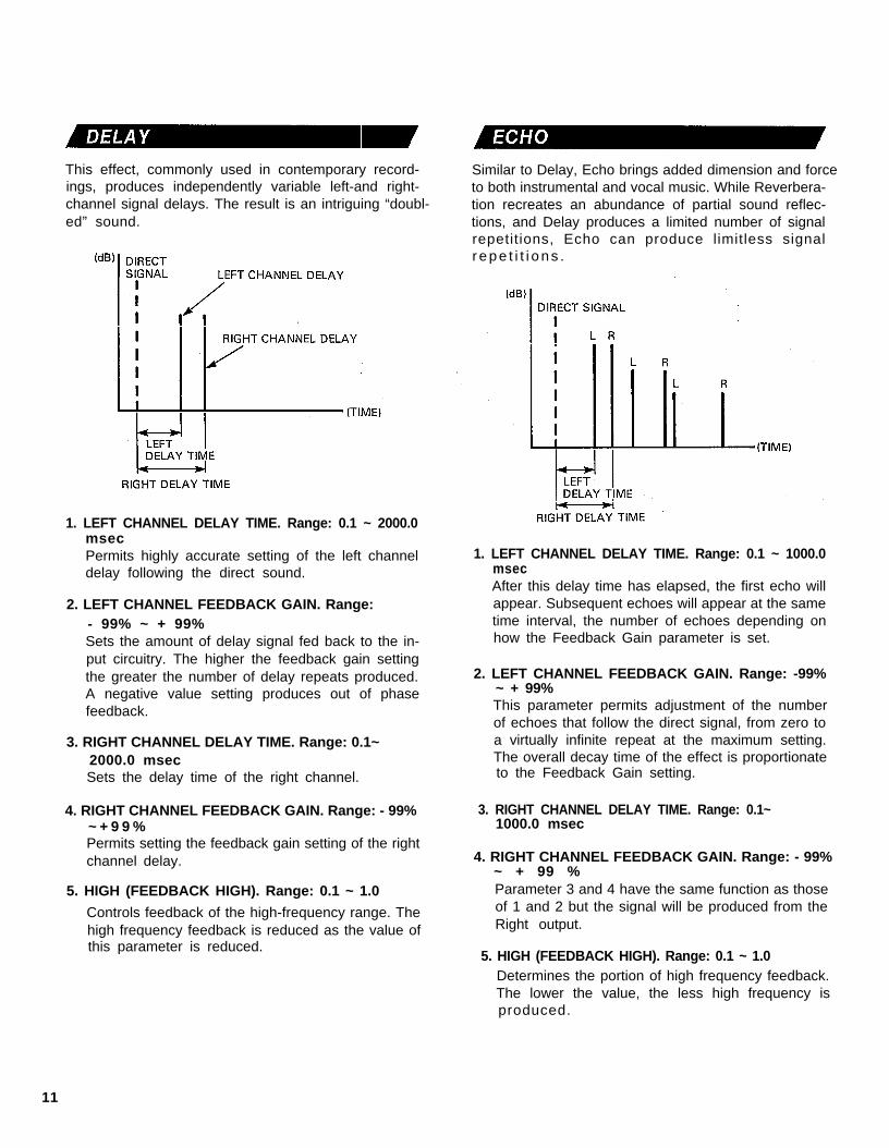
This effect, commonly used in contemporary record-ings, produces independently variable left-and right-channel signal delays. The result is an intriguing “doubl-ed” sound.
1. LEFT CHANNEL DELAY TIME. Range: 0.1 ~ 2000.0msecPermits highly accurate setting of the left channeldelay following the direct sound.
2. LEFT CHANNEL FEEDBACK GAIN. Range:- 99% ~ + 99%Sets the amount of delay signal fed back to the in-put circuitry. The higher the feedback gain settingthe greater the number of delay repeats produced.A negative value setting produces out of phasefeedback.
3. RIGHT CHANNEL DELAY TIME. Range: 0.1~2000.0 msecSets the delay time of the right channel.
4. RIGHT CHANNEL FEEDBACK GAIN. Range: - 99%~ + 9 9 %Permits setting the feedback gain setting of the rightchannel delay. 4. RIGHT CHANNEL FEEDBACK GAIN. Range: - 99%
~ + 99 %5. HIGH (FEEDBACK HIGH). Range: 0.1 ~ 1.0
Controls feedback of the high-frequency range. Thehigh frequency feedback is reduced as the value ofthis parameter is reduced.
Similar to Delay, Echo brings added dimension and forceto both instrumental and vocal music. While Reverbera-tion recreates an abundance of partial sound reflec-tions, and Delay produces a limited number of signalrepetitions, Echo can produce limitless signalr e p e t i t i o n s .
1. LEFT CHANNEL DELAY TIME. Range: 0.1 ~ 1000.0msecAfter this delay time has elapsed, the first echo willappear. Subsequent echoes will appear at the sametime interval, the number of echoes depending onhow the Feedback Gain parameter is set.
2. LEFT CHANNEL FEEDBACK GAIN. Range: -99%~ + 99%This parameter permits adjustment of the numberof echoes that follow the direct signal, from zero toa virtually infinite repeat at the maximum setting.The overall decay time of the effect is proportionateto the Feedback Gain setting.
3. RIGHT CHANNEL DELAY TIME. Range: 0.1~1000.0 msec
Parameter 3 and 4 have the same function as thoseof 1 and 2 but the signal will be produced from theRight output.
5. HIGH (FEEDBACK HIGH). Range: 0.1 ~ 1.0Determines the portion of high frequency feedback.The lower the value, the less high frequency isproduced.
11
STEREO FLANGE
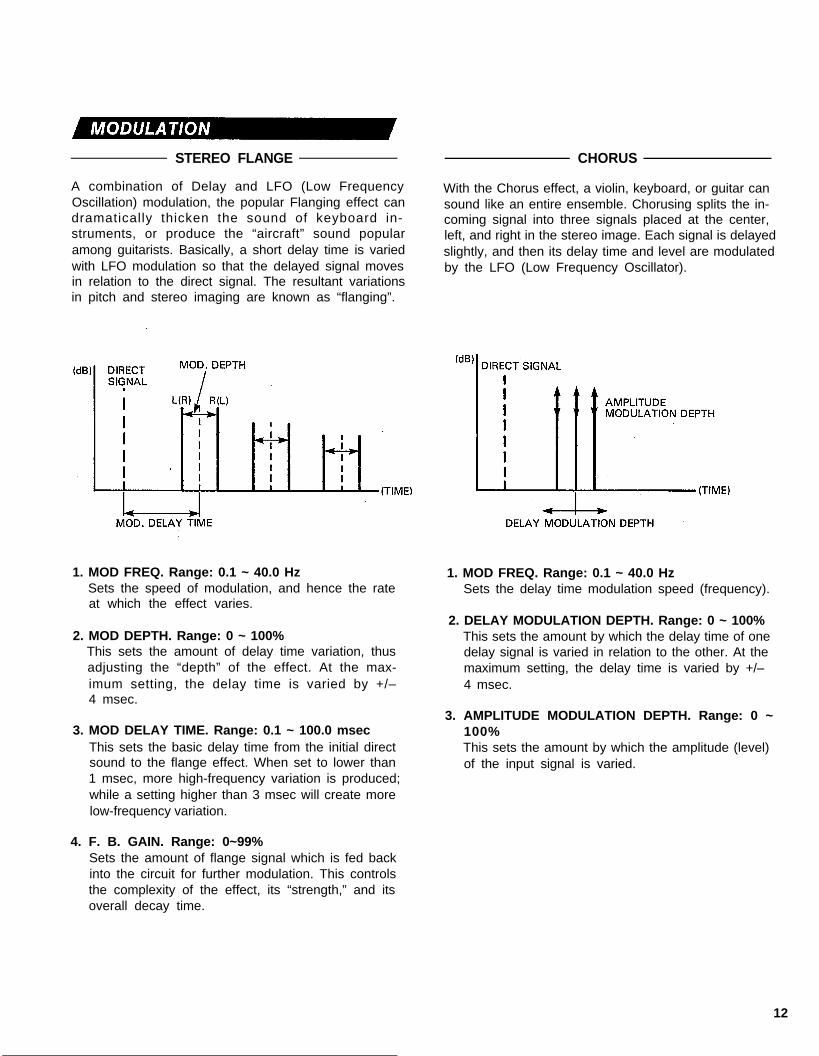
A combination of Delay and LFO (Low FrequencyOscillation) modulation, the popular Flanging effect candramatically thicken the sound of keyboard in-struments, or produce the “aircraft” sound popularamong guitarists. Basically, a short delay time is variedwith LFO modulation so that the delayed signal movesin relation to the direct signal. The resultant variationsin pitch and stereo imaging are known as “flanging”.
1. MOD FREQ. Range: 0.1 ~ 40.0 HzSets the speed of modulation, and hence the rateat which the effect varies.
2. MOD DEPTH. Range: 0 ~ 100%This sets the amount of delay time variation, thusadjusting the “depth” of the effect. At the max-imum setting, the delay time is varied by +/–4 msec.
3. MOD DELAY TIME. Range: 0.1 ~ 100.0 msecThis sets the basic delay time from the initial directsound to the flange effect. When set to lower than1 msec, more high-frequency variation is produced;while a setting higher than 3 msec will create morelow-frequency variation.
4. F. B. GAIN. Range: 0~99%Sets the amount of flange signal which is fed backinto the circuit for further modulation. This controlsthe complexity of the effect, its “strength,” and itsoverall decay time.
CHORUS
With the Chorus effect, a violin, keyboard, or guitar cansound like an entire ensemble. Chorusing splits the in-coming signal into three signals placed at the center,left, and right in the stereo image. Each signal is delayedslightly, and then its delay time and level are modulatedby the LFO (Low Frequency Oscillator).
1. MOD FREQ. Range: 0.1 ~ 40.0 HzSets the delay time modulation speed (frequency).
2. DELAY MODULATION DEPTH. Range: 0 ~ 100%This sets the amount by which the delay time of onedelay signal is varied in relation to the other. At themaximum setting, the delay time is varied by +/–4 msec.
3. AMPLITUDE MODULATION DEPTH. Range: 0 ~100%This sets the amount by which the amplitude (level)of the input signal is varied.
12

STEREO PHASING
The SPX90 II can produce a wide range of Phasing ef-fects from a barely perceptible shift to a rapid pulsa-tion. Phasing lends an animated quality to musical in-strument and vocal recordings:
This effect has the same parameters as STEREOFLANGE, except that the DELAY TIME range is from0.1 to 8.0 msec and omits FB Gain.
P R O G R A M PITCH CHANGE FEED BACK MIDI PITCHCONTROL
PITCH CHANGE A 1 TONE YES YES
PITCH CHANGE B 2TONES(CENTER) NO NOTREMOLO
The TREMOLO effect operates in the same way as theCHORUS effect, except that modulation is deeper andthe delay variation is greater. Refer to STEREO FLANGEfor the description of the parameters.
SYMPHONIC
The programmable parameters for this preset are iden-tical to those for the Stereo Flange preset, omittingFEEDBACK GAIN and MOD DELAY.
This program is used to change the pitch of an inputsignal. Pitch can be changed in semitone incrementsover a plus/minus one-octave range. Fine adjustmentof pitch in one-cent (1/100th of a semitone) incre-ments/decrements is also possible.Pitch change programs B and C permit setting two dif-ferent pitches. This makes it possible to produce har-monizer type effects (i.e. when you play a note theSPX90 II outputs two additional notes), or, if only aslight pitch difference is used, chorus-type effects arecreated.Pitch change programs A and D permit the applicationof feedback so that an echo that changes in pitch witheach repeat can be produced. Programs A and D fur-ther permit pitch control via the MIDI IN connector. AnyMIDI synthesizer, such as the Yamaha DX7, can be us-ed to alter the pitch setting of the program by simplyplaying the appropriate note on the synthesizerkeyboard.
2 TONESPITCH CHANGE C (1 EACH IN N O N O
L & R CH.)
PITCH CHANGE D 1 TONE YES YES
1. PITCH. Range: — 12 ~ + I2Sets the degree of pitch change in semitone steps.+ 12 corresponds to an output pitch one octavehigher than the input pitch, and — 12 produces anoutput pitch one octave lower than the input pitch.
2. FINE. Range: — 100 ~ + 100Adjusts pitch in one-cent increments or decrements.
3. DELAY Range: 0.1 ~ 1800.0 msec (A, B, D), 0.1-900.0 msec (C)Sets the delay between the direct (input signal) andthe pitch-changed output signal.
4. F. B. GAIN. Range: 0 ~ 99% (A, D only)The higher this setting, the more echo repeats areproduced (each changed in pitch from the previousrepeat).
5. BASE KEY. Range: OFF, C1 ~ C6 (A, D only)This parameter sets the “BASE KEY” for an exter-nal MIDI synthesizer used to control the pitch varia-
13

tion of the PITCH CHANGE program. For example,if BASE KEY = C4, then pressing the C3 key on thesynthesizer keyboard will set the pitch change valueto — 12 (one octave down). Pressing D4 on thekeyboard would produce a pitch increase of one tone(+ 2). If a key more than one octave higher or lowerthan the BASE KEY is pressed, the resultant pitchchange setting will still be within the + 12 to — 12range, as shown in the following illustration.If the BASE KEY setting is OFF, pitch can not be con-trolled via the MIDI IN terminal.
The FREEZE programs permit “recording” up to a2,000-millisecond signal in the SPX90 ll memory, andplaying it back as required. The FREEZE programs havetwo basic steps: RECORD and PLAY.With the FREEZE A program it is possible to programa specific segment of the recorded 2,000-millisecondsignal to be replayed by programming the START andEND points.The FREEZE B program does not permit programmingSTART and END points, but the pitch of the recordedsignal can be changed for playback.
1. REC. MODE Selection. Range: Manual, AutoPress the Parameter key and select the Manual modewith the Parameter Increment key or AUTO Modeby pressing the Parameter Decrement key.In the MANUAL mode a Parameter Increment panelkey is pressed to begin recording, while in the AUTOmode recording begins automatically when theSPX90 II detects an input signal.
2. TRIGGER DELAY. Range: — 2000.0 ~ 2000.0 msec.
This parameter determines the actual point at whichrecording begins in relation to the trigger signal. IfTRG DLY is set at 0, recording begins immediatelywhen the FREEZE function is triggered. If a negativeTRG DLY value is set the input signal is delayed sothat in effect recording begins before the functionis triggered.
3. RECORDINGAfter the desired MODE has been set, press thePARAMETER key and the LCD will display the“RECORD” message. Then, enter the standby modeby pressing the PARAMETER DECREMENT key. TheLCD will display the “REC READY” message.
14

TRIGGERING
MANUAL ModeTo actually begin recording if the MANUAL modehas been selected, press the PARAMETER IN-CREMENT key. The SPX90 II will record for2,000 milliseconds.Also the optional foot switch FC-5 can be used.Connect the FC-5 to the MEMORY/TRIGGERFoot Switch Jack and press the FOOT TRIGGERKey. Then FC-5 works as the trigger switch whenit is pressed.
AUTO ModeIf the AUTO mode has been. selected, theSPX90 II will automatically begin recording whenan input signal of sufficient level is detected.The LCD displays “TRIGGER!” when the freezefunction is triggered.When the recording begins the LCD displays" . . . . . "
The freeze (recording) ends automatically after2,000msec and the display says “OK”.
4. OVERDUB RecordingTo “overdub,” or record new material without eras-ing the previously recorded material, use the follow-ing procedure.
1. Press the PARAMETER key until the OVERDUBdisplay appears.
2. Press the PARAMETER DECREMENT key. Thissets the record ready status, and recording willbegin as soon as a trigger signal is received.
l FREEZE operation
* To begin recording again, pressthe parameter decrement key to enterthe Rec Ready Mode.
15

5. PLAYBACKTo play back the recorded material, press thePARAMETER key to enter the playback standbymode. The LCD will display the “PLAY” message.To actual ly play the recording, press thePARAMETER INCREMENT/DECREMENT key. Therecorded material will be played each time thePARAMETER INCREMENT/DECREMENT key ispressed.
To program a specific segment of the recording to beplayed back in the FREEZE A program, set the STARTand END parameters to appropr ia te va lues(0~2000.0). The example below depicts how theSTART and END parameters affect output.
Another way to trigger playback is to use the Input Trig-ger Parameter. Select the input Trigger Parameter andpress the parameter Increment key to enter the stand-by mode. Playback will be automatically triggered whenthe input signal exceeds nominal level.
The FREEZE B program PITCH and FINE parametersfunction identically to those in the PITCH CHANGE pro-gram to change the pitch of the playback signal.Playback start and stop can be triggered by thePARAMETER INCREMENT/DECREMENT keys, footswitch or via a MIDI keyboard connected to the MIDIIN connector. With the FREEZE B program, playing akey on the MIDI keyboard produces the correspondingpitch change in the playback output, and triggersplayback.
6. TRIGGER MASK (FREEZE A). Range: 0 ~ 2000.0 ms.This parameter makes it possible to disable playbackre-triggering for a specified time (0 ~ 2,000 msec).For example, if you wish to prevent re-triggering forthe duration of the entire sample or a portion of thesample, set the TRIGGER MASK parameter for theappropriate length of time. Once playback hasbeen triggered, it can only be triggered againafter the set TRIGGER MASK time has elapsed.
Playback can also be triggered by a footswitch con-nected to the front-panel MEMORY/FOOT TRIGGERjack when the FOOT TRIGGER key is pressed and itsLED is ON. A MIDI keyboard connected to the MIDI INterminal can also be used to trigger playback — simplyplay a note on the keyboard.
16

This program feeds the reverb signal through a gate cir-cuit, making it possible to output only a segment of alonger reverb sound. Parameters provided for the reverbporition of the signal are REV TIME, HIGH, DELAY, HPFand LPF, while parameters for the gate portion areHOLD TIME, RELEASE TIME, and MIDI TRIGGER.
ADR-NOISE GATE
This program uses a gate circuit to pass or shut off theinput signal in a number of ways. It can be used to passjust a short segment of a longer input signal, or it canbe used to pass only signals that exceed a specific level(noise-gate type operation). It is also possible to achievereverse gate effects in which the gain increasesgradually after the gate is triggered.In addition to signal-level triggering, it is also possibleto trigger the gate via a footswitch connected to thefront-panel MEMORY TRIGGER jack when the FOOTTRIGGER key LED is ON.
1. REVERB TIME (R/T). Range: 0.3 ~ 99.0 sec
2. HIGH (High Frequency Reverb Time Ratio).Range: 0.1 ~ 1.0
3. DELAY. Range: 0.1 ~ 1000.0 msec
4. HPF (High Pass Filter). Range: 32 Hz~1.0 kHz,THRU
5. LPF (Low Pass Filter). Range: 1.0 kHz~11 kHz,THRUAll these parameters have the same function asthose of the REV programs. See page 10 for details.
6. TRIGGER LEVEL. Range: 0 ~ 100%Determines the strength (amplitude) of the inputsignal required to trigger opening of the gate. At100%, only extremely high-level input signals willtrigger the gate, while at 0% even this slightest in-put signal will trigger the gate.
7. HOLD TIME. Ragne: 1~30,000 msecThis parameter sets the amount of time the gate is“open,” allowing the reverb sound to come through.
8. RELEASE TIME. Range: 5~32,000 msecThis parameter determines the time it takes fot thegate to close completely after the HOLD TIME.
9. MIDI TRIGGER. Range: ON, OFFWhen ON, a KEY ON signal from an external MIDIkeyboard can be used to trigger the R & G effect.
17
1. TRIGGER LEVEL. Range: 1~100%Determines the strength (amplitude) of the inputsignal required to trigger opening of the gate. At100%, only extremely high level input signals willtrigger the gate, while at 0% even the slightest in-put signal will trigger the gate.
2. TRIGGER DELAY. Range: — 100 ~ 100 msec‘Produces a delay between the time at which thegate is triggered and that at which it actually opens.If a minus value is programmed, the input signalitself is delayed so that, effectively, the gate opensbefore the signal appears.
3. TRIGGER MASK. Range: 5~32,000 msecThis parameter makes it impossible to re-trigger thegate function until the programmed time haselapsed.
4. ATTACK TIME. Range: 5 msec ~ 32,000 msecDetermines how long it takes for the gate to openfully from the time it begins to open.
5. DECAY TIME. Range: 5 msec ~ 32,000 msecDetermines the length of time it takes for the gateto fall to DECAY LEVEL after it is fully open.

6. DECAY LEVEL. Range: 0 ~ 100%Determines the level at which the gate remains openfor the HOLD TIME. The lower the value the lowerthe HOLD gate level.
7. HOLD TIME. Range: 1 msec ~ 30,000 msecDetermines how long the gate stays open, allowingthe input signal to pass.
8. RELEASE TIME. Range: 5 msec ~ 32,000 msecDetermines how long it takes for the gate to closefully from the time it begins to close.
9. MIDI TRIGGER. Range: ON, OFFWhen ON, a KEY ON signal from an external MIDIkeyboard can be used to trigger the gate.
COMPRESSOR
The COMPRESSOR effect reduces the level of the attackportion of a music signal and keeps overall signal levelwithin narrow limits.
1. TRIGGER LEVEL. Range: 1 ~ 100%Determines the strength of the attack signal requiredto trigger the compressor effect.
2. TRIGGER DELAY. Range: — 100 ~ 100 msecProduces a delay between the time at which the ef-fect is triggered and that at which the compressionactually begins. If a negative value is programmed,the input signal is delayed so that effectively, thecompression begins before the signal appears.
3. TRIGGER MASK. Range: 5 ~ 32,000 msecThis parameter makes it impossible to re-trigger thecompressor function until the programmed time haselapsed.
4. ATTACK TIME. Range: 5 msec ~ 32,000 msecDetermines how long it takes until the HOLD level(below) is reached after the effect is triggered.
5. HOLD TIME. Range: 1 msec ~ 30,000 msecDetermines how long the maximum compression ef-fect is maintained after the ATTACK TIME haselapsed.
6. HOLD LEVEL. Range: 0 ~ 100%Determines the actual level to which all input signalswill be compressed during the HOLD TIME. Thesmaller the value, the lower the level of the outputs i g n a l .
7. RELEASE TIME. Range: 5 msec ~ 32,000 msecDetermines how long it takes to return to normallevel once the HOLD TIME has elapsed.
8. MIDI TRIGGER. Range: ON, OFFWhen ON, a KEY ON signal from an external MIDIkeyboard can be used to trigger the compressoreffect.
18

PAN TRIGGERED PAN
This program automatically pans the sound image bet- In this program the pan effect is triggered by the inputween left and right in the stereo sound field. Pan direc- signal or footswitch.tion, speed, and phase can be programmed.
1.1. PAN SPEED. Range: 0.1 ~ 40.0 Hz
Sets the speed of pan.
2. DIRECTION. Range: L R,Determines the direction of
3. DEPTH. Range: 0 ~ 100%
L R , L Rpan.
2.
Sets the degree of level variation. The higher thevalue, the stronger the pan effect.
3.
4.
5.
6.
7.
8.
9.
TRIGGER LEVEL. Range: 1 ~ 100%Determines the strength of the attack signal requiredto trigger the pan effect. The higher the value, thehigher the input signal level required to trigger theeffect.
TRIGGER DELAY. Range: - 100 ~ 100 msecProduces a delay between the time at which the ef-fect is triggered and that at which the pan effect ac-tually begins. If a negative value is programmed, theinput signal is delayed so that effectively, the paneffect begins before the signal appears.
TRIGGER MASK. Range: 5 ~ 32,000 msecThis parameter makes it impossible to re-trigger thepan function until the programmed time has elapsed.
ATTACK TIME. Range: 5 met ~ 32,000 msecDetermines how quickly or slowly the pan effectreaches maximum depth after it is triggered.
PANNING TIME. Range: 5 msec ~ 32,000 msecDetermines how long the maximum-depth pan ef-fect remains active.
RELEASE TIME. Range: 5 msec ~ 32,000 msecDetermines how long it takes for the pan effect tofade out after the PANNING TIME has elapsed.
DIRECTION. Range: L R, L RSets the direction of pan.
L/R BALANCE. Range: 0 ~ 100%Determines the volume balance between the left andright channels.
MIDI TRIGGER. Range: ON, OFFWhen ON, a KEY ON signal from an external MIDIkeyboard can be used to trigger the pan effect.
NOTE: To use footswitch FC-5, connect the FC-5 tothe MEMORY/TRIGGER FOOT Switch Jack andpress the Foot Trigger key.
19
This program makes it possible to add delay vibrato ef-fects to virtually any instrument or sound. When theinput signal exceeds a programmed trigger level, thevibrato effect is cancelled and then gradually builds upto the programmed depth.
1. TRIGGER LEVEL. Range: 1 ~ 100%Determines the input signal level at which thevibrato effect is cancelled and begins to build upagain.
2. VIBRATO DELAY. Range: 1 ~ 30,000 msecDetermines how long the vibrato effect is cancell-ed once triggered.
3. VIBRATO RISE TIME. Range: 5 msec ~ 32,000msecDetermines how long it takes for the vibrato effectto reach maximum depth after the VIBRATO DELAYtime has elapsed.
4. VIBRATO FREQUENCY. Range: 0.1 ~ 20.0 HzThis parameter sets the frequency (speed) of thevibrato effect.
5. VIBRATO DEPTH. Range: 0 ~ 100%Sets the depth (strength) of the vibrato effect.
6. MIDI TRIGGER. Range: ON, OFFWhen ON, a KEY ON signal from an external MIDIkeyboard can be used to trigger the vibrato effect.
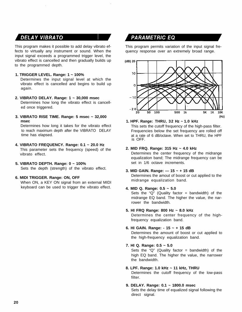
This program permits variation of the input signal fre-quency response over an extremely broad range.
(dB) 20
- 2 020 50 100 500 1k 5K 1K 10K
(Hz)
1. HPF. Range: THRU, 32 Hz ~ 1.0 kHzThis sets the cutoff frequency of the high-pass filter.Frequencies below the set frequency are rolled offat a rate of 6 dB/octave. When set to THRU, the HPFis OFF.
2. MID FRQ. Range: 315 Hz ~ 4.0 kHzDetermines the center frequency of the midrangeequalization band; The midrange frequency can beset in 1/6 octave increments.
3. MID GAIN. Range: — 15 ~ + 15 dBDetermines the amout of boost or cut applied to themidrange equalization band.
4. MID Q. Range: 0.5 ~ 5.0Sets the “Q” (Quality factor = bandwidth) of themidrange EQ band. The higher the value, the nar-rower the bandwidth.
5. HI FRQ Range: 800 Hz ~ 8.0 kHzDetermines the center frequency of the high-frequency equalization band.
6. HI GAIN. Range: - 15 ~ + 15 dBDetermines the amount of boost or cut applied tothe high-frequency equalization band.
7. HI Q. Range: 0.5 ~ 5.0Sets the “Q” (Quality factor = bandwidth) of thehigh EQ band. The higher the value, the narrowerthe bandwidth.
8. LPF. Range: 1.0 kHz ~ 11 kHz, THRUDetermines the cutoff frequency of the low-passfilter.
9. DELAY. Range: 0.1 ~ 1800.0 msecSets the delay time of equalized signal following thedirect signal.
20
SAMPLE APPLICATlONS
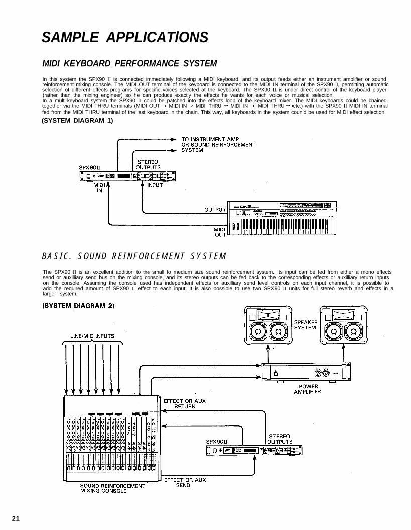
MIDI KEYBOARD PERFORMANCE SYSTEM
In this system the SPX90 II is connected immediately following a MIDI keyboard, and its output feeds either an instrument amplifier or soundreinforcement mixing console. The MIDI OUT terminal of the keyboard is connected to the MIDI IN terminal of the SPX90 II, permitting automaticselection of different effects programs for specific voices selected at the keyboard. The SPX90 II is under direct control of the keyboard player(rather than the mixing engineer) so he can produce exactly the effects he wants for each voice or musical selection.In a multi-keyboard system the SPX90 II could be patched into the effects loop of the keyboard mixer. The MIDI keyboards could be chainedtogether via the MIDI THRU terminals (MIDI OUT MIDI IN MIDI THRU MIDI IN MIDI THRU etc.) with the SPX90 II MIDI IN terminalfed from the MIDI THRU terminal of the last keyboard in the chain. This way, all keyboards in the system counld be used for MIDI effect selection.
(SYSTEM DIAGRAM 1)
B A S I C . S O U N D R E I N F O R C E M E N T S Y S T E M
The SPX90 II is an excellent addition to the small to medium size sound reinforcement system. Its input can be fed from either a mono effectssend or auxilliary send bus on the mixing console, and its stereo outputs can be fed back to the corresponding effects or auxilliary return inputson the console. Assuming the console used has independent effects or auxilliary send level controls on each input channel, it is possible toadd the required amount of SPX90 II effect to each input. It is also possible to use two SPX90 II units for full stereo reverb and effects in alarger system.
21

RECORDING SYSTEM
In a recording system it is most desirable to have the SPX90 II input and outputs available at a patch bay where they may accessed and patchedinto virtually any part of the system. In some cases it might be best to have the SPX90 II connected directly in line between the source andthe mixing console inputs, while in other situations-final mixdown, for example-the SPX90 II should be patched into the mixing console’seffects loop so it may be applied to the entire mix. Naturally, the SPX90 II is also an ideal choice for the truly modern digital sequencer recordingsystem, too.
(SYSTEM DIAGRAM 3)
ELECTRIC GUITAR SYSTEM
The SPX90 II is undoubtedly the ultimate electric guitar effect unit, An electric guitar can be plugged directly into the SPX90 II INPUT jack,and the desired effect selected via the front panel or using the footswitch memory recall function. Even more versatility can be achieved byusing a Yamaha MFC1 MIDI Foot Controller for program selection. Specified programs can be directly selected using the MFC1 footswitches,or a “chain” can be set up to automatically select a specified sequence of programs.
(SYSTEM DIAGRAM 4)
22

SPECIFICATIONS
Number of ChannelsNominal LevelImpedanceLevel ControlLevel Monitor
A/D CONVERSION
Unbalanced x 1 (Phone Jack)- 20 dBm/+4 dBm, Selectable10 k-ohmsVolume, Max, Gain + 12 dB7 points LED
Sampling Freq.QuantizationBand WidthNumber of Channels
31.25 kHzLinear 16 Bit20 Hz to 12 kHz1
D/A CONVERSION
Number of ChannelsSampling Freq.QuantizationBand Width
231.25 kHzLinear 16 Bit20 Hz to 12 kHz
O U T P U T
Number of ChannelsNominal LevelImpedanceMixingBypass
Unbalanced x 2 (Phone Jack)- 20 dBm/+4 dBm, Selectable600 ohmsDirect Signal, Effect SignalON/OFF
MEMORYPresets (ROM)User Memory (RAM)
1 ~ 3 031 ~ 90 (Non Volatile)All parameters except Input Level,can be memorizedKey On triggers the program 18,19, 20, 28 and 29
MIDI CONTROL MIDI Channel (1 to 16, OMNI), (4banks), Program Number (1 to128)Note on/off is recognized only forpitch change A, D-and freeze B
FRONT PANELDisplay
K n o bK e y s
16 character 2 lines LCD x 1, 2digits numeric LED for MemoryNo., 7 points level meter LEDInput Level VolumeParameter/Balance/Data Incre-ment/Data Decrement, MemoryStore/ Recall/Memory numberIncrement/Memory numberDecrement, Utility/Foot Trigger/Bypass
ELECTRICAL CHARACTERISTICSDynamic Range Reverb: more than 75 dB
Delay : more than 81 dBDistortion Bypassed Signal : less than
0.01%Effect Signal less than
0 . 0 3 %Band Width Bypassed Signal : 20 Hz to 20
k H zEffect Signal : 20 Hz to 12
k H z
POWER SUPPLYU. S. & Canadian Models 1.10V-120V, 60HzGeneral Model 220V-240V, 50/60Hz
POWER CONSUMPTIONU. S. & Canadian Models 20WGeneral Model 20W
DIMENSIONS 480mm x 45.2mm x 285mm(W x H x D) (18-7/8” x 1-3/4” x 11-1/4”)
WEIGHT 3.2 kg (7 Ibs)
OPTIONAL REMOTE CONTROL PRESET PROGRAM 1~30, USER(model RC7) MEMORY 31-37
OPTIONAL MIDI FOOT CONTROLLER (model MFC1) Memory Mode 4 + 4 PGM change numbersChain Mode 20 Step x 4 PGM change, control
change data, MIDI start, stop,continue commands
* NOTE:Since natural sounding reverberation is mixed with thedirect sound, and hence does not constitute 100% of thesound, the effective dynamic range will nearly always exceed90 dB.0 dBu is 0.775 volts RMS. This value represents voltage acrossa high impedance input dBu is the equivalent of dBu if specifiedacross a 600 ohm load.
23

ROM CONTENTS AND CONTROLABLE PARAMETERS
24 25

EARLY REFLECTION MODE CHART ROOM SIZE CHART
ROOM SIZE : 1.0 HALL ROOM SIZE : 4.0
ROOM SIZE : 1.0 RANDOM ROOM SIZE : 4.0
ROOM SIZE : 1.0 REVERSE ROOM SIZE : 4.0
ROOM SIZE : 1.0 PLATE ROOM SIZE : 4.0
26 27

BLOCK DIAGRAM
DIMENSIONS
Unit : mm (Inch)
28

USER PROGRAMMING TABLE
29

[ Digital Sound processor ] Date : 11/28, 1980Model SPX90-2 MIDI Implementation Chart Version : 1.0
Recognized Remarks Function . . .
Basic Default 1 - 16 memorizedChannel Changed 1 - 16
Default OMNI OFF/OMNI ON memorizedMode Messages : x
Altered x
Note o 0 - 127 *1Number : True voice
Velocity Note ON xNote OFF x
After Key's xTouch Ch's x
Pitch Bander x
x
x
Control
Change
Prog o 0-127 x2 Change: True #
System Exclusive o
System: Song Pos x: Song Se1 x
Common : Tune x
System :Clock xReal Time :Commands
Aux :Local ON/OFF:All Notes OFF
Mes-:Active Sensesages:Reset x
Notes *l Note ON/OFF is recognized only for pitchchange and freeze B,*2 For program 1 - 128, memory #l - #90 isselected.
Mode 1:OMNI ON, POLY Mode 2 : OMNI ON, MONO o : YesMode 3 : OMNI OFF, POLY Mode 4 : OMNI OFF, MONO x : No
xxx
x

SINCE 1887 Y A M A H ANIPPON GAKKI CO., LTD. HAMAMATSU, JAPAN
SERVICEThe SPX90II is supported by Yamaha’s worldwide networkof factory trained and qualified dealer service personnel. Inthe event of a problem, contact your nearest Yamaha dealer.
Printed in Japan