Embed Size (px)
Citation preview

������������™
Crane Kits¼ - 5 Ton Capacity
Spans to 48 feet
Specifications
Distributed by Tri-State Equipment Company Inc. | [email protected] | (314) 869-7200 | www.tsoverheadcrane.com

This Yale•Lift-Tech bulletin contains specifications and clearancesfor single girder crane kits with spans to 48' and capacities to 5 ton.These bridge kits are available in a wide variety to meet the exactrequirements of your crane application.
Index
Subject Page No.
UnderhungPush Type Kits ............................................................................... 3-5Hand Geared Kits .......................................................................... 6-7Motor Driven Kits ......................................................................... 8-13
Top RunningPush and Hand Geared Kits ...................................................... 14-16Motor Driven Kits ....................................................................... 17-22
General Information .................................................................... 23-24

3
������������™
MaximumCapacity
(tons)
MaximumSpan(ft)
KitCode
Runway BeamFlange
Adj. Range Wheel Type
WheelSize(in)
Max. WheelLoad Per Pair
(lbs)
ApproximateShippingWt. (lbs)
Angle Construction Trucks
1/2 30 905360
3" - 8"Pressed Steel Wheels
4 1444 3001 24
905360
905360SR Spark Resistant Wheels
2 30
9053613-3/8" - 8"
Pressed Steel Wheels 5
2730
310
905362 Forged Steel Wheels
4 320905362PT 3-1/4" Patented Track Wheels
905362SR 3-3/8" - 8" Spark Resistant Wheels
Channel Construction Trucks
336
905368 3-3/8" - 5-1/2"
Forged Steel Wheels
4 4240
380
905368W1 5-1/2" - 8" 390
905368W2 8" - 10-1/2" 400
905368SR 3-3/8" - 5-1/2" Spark Resistant Wheels380
905368PT 3-1/4" Patented Track Wheels
24 905368S 3-3/8" - 5-1/2" 3’ - 0" Short Wheelbase 330
536
905524 4" - 6-1/4"
Forged Steel Wheels
6-1/2 7520
550
905524W1 6-3/8" - 9" 560
905524W2 9" - 11-1/2" 570
905524PT 3-1/4" Patented Track Wheels550
905524SR4" - 6-1/4"
Spark Resistant Wheels
24 905524S 3’ - 0" Short Wheelbase 495
Capacity 1/2 - 5 tons/Spans to 36 feetThese Crane bridge kits contain all the parts needed to buildunderhung single girder crane bridges, except the bridge beam,cross shaft and trolley stop angles. An illustrated, easy-to-understand assembly manual is included in each kit.
Push type kits contain:Each kit includes one pair of end trucks and the requiredhardware for attaching truck frames to bridge I-Beam.
Push Type Underhung Crane Kits
Crane Component - UnderhungPush Type Crane Bridge Kits
Material to be Purchased Locally:• One length of American Standard Section I-Beam or wide
flange which must be a minimum length of 16 inches longerthan the span for 3-ton bridge and 18-1/2 inches longer than thespan for 5-ton bridge. See chart on page 5 to select properbeam size and the charts on page 4 for outline dimensions.
• Four trolley stop angles must be cut to size and attached tobridge beam.

4
������������™Crane Component - Underhung
Push Type Crane Bridge Kits
Push type bridges withangle end trucksCatalog 905360, 905361 and905362
Push type bridges withchannel end trucksCatalog 905368 and 905524

5
������������™
ProductCode
RatedCapacity*
(tons)
Max.Span(ft)
Runway Beam Sizes**
A B C D E
FWheel
Dia.G
Min. H J† K
MinBeamWidth
Min.FlangeWidth
Max.FlangeWidth
Push Type Kit
9053601/2 30
S5x10 3
8
1-1/4 6-1/16
—
1-5/8 4-13/16 48
— 4-3/4 2' - 1-3/4"1 24
9053612 30
S6x12.5 3-3/8
1-3/8 6-1/4 1-1/16 5-7/8 5
905362 1-1/4 6-11/16 1-9/16 5-13/164 8-1/4
905368 336
5-1/2 1-1/8 7-13/16 15/16 1-7/16 5-1/8 14 4 2' - 7"
905524 5 S8x18.4 4 6-1/4 3/4 8-11/16 13/16 1-5/16 8 6-1/2 9-3/8 14-5/8 5-1/2 2' - 8-5/8"
ForSpansto (ft)
Rated Capacity* (tons)
1/4 1/2 1 1-1/2 2 3 4 5
10 S6x12.5 S7x15.3 S7x15.3 S8x18.4 S10x25.4 S12x40.8 S12x40.8 S12x40.8
12 S6x12.5 S7x15.3 S7x15.3 S10x25.4 S10x25.4 S12x40.8 S12x40.8 S18x54.7
14 S7x15.3 S7x15.3 S7x15.3 S10x25.4 S12x31.8 S12x40.8 S12x40.8 S18x54.7
16 S7x15.3 S7x15.3 S8x18.4 S10x25.4 S12x31.8 S12x40.8 S12x40.8 S18x54.7
18 S7x15.3 S7x15.3 S10x25.4 S10x25.4 S12x31.8 S12x40.8 S15x42.9 S18x54.7
20 S7x15.3 S8x18.4 S10x25.4 S12x31.8 S12x31.8 S12x40.8 S18x54.7 S18x54.7
22 S8x18.4 S10x25.4 S10x25.4 S12x31.8 S12x40.8 S18x54.7 S18x54.7 S20x66
24 S8x18.4 S10x25.4 S12x31.8 S12x40.8 S12x40.8 S18x54.7 S18x54.7 S20x66
26 S10x25.4 S10x25.4 S12x31.8 S12x40.8 S15x42.9 S18x54.7 S20x66 S24x80
28 S10x25.4 S10x25.4 S12x40.8 S12x40.8 S18x54.7 S20x66 S20x66 S24x80
30 S10x25.4 S12x31.8 S12x40.8 S18x54.7 S18x54.7 S20x66 S18x54.7C9x13.4 S24x80
32 S10x25.4 S12x31.8 S12x40.8 S18x54.7 S15x42.9C8x11.5 S18x54.7C9x13.4 S18x54.7C9x13.4 S20x66C9x13.4
34 S12x31.8 S12x40.8 S15x42.9 S18x54.7 S15x42.9C8x11.5 S18x54.7C9x13.4 S18x54.7C9x13.4 S20x66C9x13.4
36 S12x31.8 S12x40.8 S18x54.7 S15x42.9C8x11.5 S15x42.9C8x11.5 S18x54.7C9x13.4 S20x66C9x13.4 S20x66C9x13.4
Bridge Girder Beam Sizes For - Push or Hand Geared Crane**
Clearance Dimensions (in.) For Push Type Cranes
**Runway beam sizes shown indicate range of beams that trucks will fit. For proper runway size, consult qualified engineer or architect.End trucks for wider flange beams or 3-1/4" patented track are available.Dimensions A, B, C, D and E are based on minimum beam.
† Dimension with rubber bumpers: 3 ton catalogs 905368 = 7 3/8 and 5 ton catalogs 905524 = 8-7/8.
* Rated capacity is based on maximum combined hoist and trolley weights of 500 pounds for 1/4, 1/2 and 1 ton hoists; 1100 pounds for 1 1/2 and2 ton hoists; 1600 pounds for 3 and 4 ton hoists; 2000 pounds for 5 ton hoists. Bridge designed in accordance with CMAA Specification No. 74.
**Beam sizes listed are American Standard I-Beam and channel sections. Use ASTM A36 grade steel, first quality, free of rust and excessive millscale.
Crane Component - UnderhungPush & Hand Geared Crane Bridge Kits

6
������������™
Max.Capacity
(tons)
Max.Span(ft)
KitCode
EndTruckCode
Number
Kit Consists Of:
WheelSizeandType
Max.WheelLoad
per pair(lbs)
Approx.Shippingwt. (lbs)
Cross ShaftSupport Assembly
Cross ShaftCoupling
Qty.Code
Number Qty.Code
Number
Standard
15 B03/15UHG
9053694’ - 6" WB
1
905373
2
905374
4" dia.geared
solid forgedsteel
wheels
4240
440
22 B03/22UHG 2 2 442
3 29 B03/29UHG 3 3 446
36 B03/36UHG 4 3 448
5
15 B05/15UHG
9055254’ - 6" WB
1 2 6-1/2" dia.geared
solid forgedsteel
wheels
7520
520
22 B05/22UHG 2 2 522
29 B05/29UHG 3 3 526
36 B05/36UHG 4 3 528
Spark Resistant
3
15 B03/15UHGSR
905369SR4’ - 6" WB
1
905373
2
905374
4" dia.gearedbronzewheels
4240
480
22 B03/22UHGSR 2 2 482
29 B03/29UHGSR 3 3 486
36 B03/36UHGSR 4 3 488
5
15 B05/15UHGSR
905525SR4’ - 6" WB
1 26-1/2" dia.
gearedbronzewheels
7520
570
22 B05/22UHGSR 2 2 572
29 B05/29UHGSR 3 3 576
36 B05/36UHGSR 4 3 578
Kit Consists of: 904550 Hand Chain Wheel 2 End Trucks Shaft Diameter is 1"36' Hand Chain Cross Shaft Support as noted above For Runway Flange Widths of 33/8" - 5½" 3 ton1 Hand Chain Link Cross Shaft Coupling as noted above For Runway Flange Widths of 4" - 6¼" 5 ton
Crane Component - UnderhungHand Geared Crane Bridge Kits
Capacity 1/2 - 5 tons/Spans to 36 feetThese Crane bridge kits contain all the parts needed to buildunderhung single girder crane bridges, except the bridge beam,cross shaft and trolley stop angles. An illustrated, easy-to-understand assembly manual is included in each kit.
Hand geared kits contain:
• End trucks (1 pair) complete with driving pinion andattachment hardware
• Cross shaft support (quantity based upon span)• Drive couplings (quantity based upon span)• Chain wheel and chain guide• 36 foot length of hand chain with open connecting link
Material to be Purchased Locally:• One length of American Standard Section I-Beam or wide
flange which must be a minimum length of 16 inches longerthan the span for 3-ton bridge and 18-1/2 inches longer thanthe span for 5-ton bridge. See chart on page 5 to select proper
beam size and the chart on page 7 for outline dimensions.
• Four trolley stop angles must be cut to size and attached tobridge beam.
• Hand Geared Bridges Only. One inch diameter cross shaft isrequired. Length depends on span and is determined byreferring to outline dimensions on page 7.

7
������������™
ProductCode
RatedCapacity
(tons)
Max.Span(ft)
Runway Beam Sizes**
A B C D E
FWheelDia.
GMin. H J† K
MinBeamWidth
Min.FlangeWidth
Max.FlangeWidth
Hand Geared Type End Trucks
905369 336
S6x12.5 3-3/8 5-1/2 1-1/8 7-13/16 15/16 1-7/16 5-1/8 4 8-1/4 14 5-1/4 2’ - 7"
905525 5 S8x18.4 4 6-1/4 3/4 8-11/16 13/16 1-5/16 8 6-1/2 9-3/8 14-5/8 5-1/2 2’ - 8-5/8"
Crane Components - UnderhungHand Geared Crane Bridge Kits
Hand geared bridges withchannel end trucksCatalog 905369 and 905525
**Runway beam sizes shown indicate range of beams that trucks will fit. For proper runway size, consult qualified engineer or architect.End trucks for wider flange beams or 3-1/4" patented track are available.Dimensions A, B, C, D and E are based on minimum beam.
† Dimension with rubber bumpers: 3 ton catalogs 905369 = 7 3/8 and 5 ton catalogs 905525 = 8-7/8.
Clearance Dimensions (in.)

8
������������™
Max.Capacity
(tons)
Max.span(ft)
Speed(fpm)
KitCode
1 Speed
Kit Consists Of:Approx Shipping
(lbs)
EndTrucksCode
NumberGear
Reducer
CrossShaft
Support(Qty)
CrossShaft
Coupling(Qty)
Controls&
Motors1
Speed2
Speed
1/4thru
3
8
55 B03/08UC*55
9053694’-6" WB
905378
0
21 eachControl
1 each½ hp motor
1 eachDisconnect
(see below)
524 54470 B03/08UC*70 905377
110 B03/08UC*110 905376
15
55 B03/15UC*55 905378
1 544 56470 B03/15UC*70 905377
110 B03/15UC*110 905376
22
55 B03/22UC*55 905378
2 564 58470 B03/22UC*70 905377
110 B03/22UC*110 905376
29
55 B03/29UC*55 905378
3
3
586 60670 B03/29UC*70 905377
110 B03/29UC*110 905376
36
55 B03/36UC*55 905378
4 606 62670 B03/36UC*70 905377
110 B03/36UC*110 905376
For runway flange width of 3-3/8" - 5-1/2"Max wheel load per pair - 4240 lbs.Wheels - 4" diameter solid forged steel
* Specify: 1 = Single Speed2 = Two Speed
Motor and Controls for Single Drive Underhung Cranes
Single phase availableNEMA1 Enclosures Standard
Crane Components - UnderhungMotor Driven Crane Bridge Kits
Motor Driven with Single DriveCapacity 1/4 to 3 ton/Spans to 36 feet
208 - 230 Volt 460 Volt 575 volt
1/2 hp Motor(1) req’d
Control(1) req’d
DisconnectSwitch
(1) req’d1/2 hp Motor
(1) req’dControl(1) req’d
DisconnectSwitch
(1) req’d1/2 hp Motor
(1) req’dControl(1) req’d
DisconnectSwitch
(1) req’d
Single Speed
905381 44600301 905388 905381 44600303 905389 905382 44600304 905389
Two Speed
905394 44600341 905388 905395 44600343 905389 905396 44600344 905389

9
������������™
Max.Capacity
(tons)
Max.span(ft)
Speed(fpm)
KitCode
1 Speed
Kit Consists Of:Approx Shipping
(lbs)
EndTrucksCode
NumberGear
Reducer
CrossShaft
Support(Qty)
CrossShaft
Coupling(Qty)
Controls&
Motors1
Speed2
Speed
1/4thru
5
8
50 B05/08UC*50
9055254’-6" WB
905378
0
21 eachControl
1 each½ hp motor
1 eachDisconnect
(see below)
644 66465 B05/08UC*65 905377
100 B05/08UC*100 905376
15
50 B05/15UC*50 905378
1 664 68465 B05/15UC*65 905377
100 B05/15UC*100 905376
22
50 B05/22UC*50 905378
2 684 70465 B05/22UC*65 905377
100 B05/22UC*100 905376
29
50 B05/29UC*50 905378
3
3
704 72465 B05/29UC*65 905377
100 B05/29UC*100 905376
36
50 B05/36UC*50 905378
4 724 74465 B05/36UC*65 905377
100 B05/36UC*100 905376
Crane Components - UnderhungMotor Driven Crane Bridge Kits
– For Runway Flange Widths of 4”-6¼”*Specify: 1=Single Speed Max wheel load per pair - 7520 lbs.
2=Two Speed Wheels - 6½" diameter solid forged steel
Motor and Controls for Single Drive Underhung Cranes
Single phase availableNEMA1 Enclosures StandardControl panel includes mainline contactor, bridge fusing, reversing contactor and 115 volt control circuit transformer.
Motor Driven with Single DriveCapacity 1/4 - 5 ton/Spans to 36 feet
208 - 230 Volt 460 Volt 575 volt
1/2 hp Motor(1) req’d
Control(1) req’d
DisconnectSwitch
(1) req’d1/2 hp Motor
(1) req’dControl(1) req’d
DisconnectSwitch
(1) req’d1/2 hp Motor
(1) req’dControl(1) req’d
DisconnectSwitch
(1) req’d
Single Speed
905381 44600301 905388 905381 44600303 905389 905382 44600304 905389
Two Speed
905394 44600341 905388 905395 44600343 905389 905396 44600344 905389
10
������������™
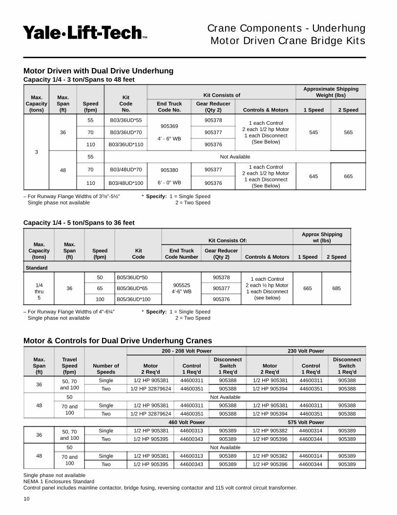
Max.Span(ft)
TravelSpeed(fpm)
Number ofSpeeds
200 - 208 Volt Power 230 Volt Power
Motor2 Req’d
Control1 Req’d
DisconnectSwitch1 Req’d
Motor2 Req’d
Control1 Req’d
DisconnectSwitch1 Req’d
3650, 70
and 100Single 1/2 HP 905381 44600311 905388 1/2 HP 905381 44600311 905388
Two 1/2 HP 32879624 44600351 905388 1/2 HP 905394 44600351 905388
48
50 Not Available
70 and100
Single 1/2 HP 905381 44600311 905388 1/2 HP 905381 44600311 905388
Two 1/2 HP 32879624 44600351 905388 1/2 HP 905394 44600351 905388
460 Volt Power 575 Volt Power
3650, 70
and 100Single 1/2 HP 905381 44600313 905389 1/2 HP 905382 44600314 905389
Two 1/2 HP 905395 44600343 905389 1/2 HP 905396 44600344 905389
48
50 Not Available
70 and100
Single 1/2 HP 905381 44600313 905389 1/2 HP 905382 44600314 905389
Two 1/2 HP 905395 44600343 905389 1/2 HP 905396 44600344 905389
Max.Capacity
(tons)
Max.Span(ft)
Speed(fpm)
KitCodeNo.
Kit Consists ofApproximate Shipping
Weight (lbs)
End TruckCode No.
Gear Reducer(Qty 2) Controls & Motors 1 Speed 2 Speed
3
36
55 B03/36UD*55905369
4’ - 6" WB
905378 1 each Control2 each 1/2 hp Motor1 each Disconnect
(See Below)
545 56570 B03/36UD*70 905377
110 B03/36UD*110 905376
48
55 Not Available
70 B03/48UD*70 905380
6’ - 0" WB
905377 1 each Control2 each 1/2 hp Motor1 each Disconnect
(See Below)
645 665110 B03/48UD*100 905376
Max.Capacity
(tons)
Max.Span(ft)
Speed(fpm)
KitCode
Kit Consists Of:Approx Shipping
wt (lbs)
End TruckCode Number
Gear Reducer(Qty 2) Controls & Motors 1 Speed 2 Speed
Standard
1/4thru
5
36
50 B05/36UD*50
9055254’-6" WB
905378 1 each Control2 each ½ hp Motor1 each Disconnect
(see below)
665 68565 B05/36UD*65 905377
100 B05/36UD*100 905376
Motor Driven with Dual Drive UnderhungCapacity 1/4 - 3 ton/Spans to 48 feet
– For Runway Flange Widths of 33/8”-5½” * Specify: 1 = Single SpeedSingle phase not available 2 = Two Speed
Crane Components - UnderhungMotor Driven Crane Bridge Kits
Motor & Controls for Dual Drive Underhung Cranes
Capacity 1/4 - 5 ton/Spans to 36 feet
Single phase not availableNEMA 1 Enclosures StandardControl panel includes mainline contactor, bridge fusing, reversing contactor and 115 volt control circuit transformer.
– For Runway Flange Widths of 4”-6¼” * Specify: 1 = Single SpeedSingle phase not available 2 = Two Speed
11
������������™
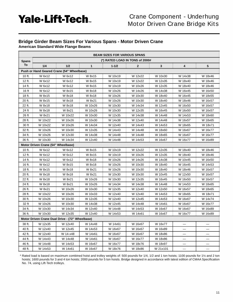
BEAM SIZES FOR VARIOUS SPANS
SpansTo
(*) RATED LOAD IN TONS of 2000#
1/4 1/2 1 1-1/2 2 3 4 5
Push or Hand Geared Crane (54" Wheelbase)
10 ft. W 6x12 W 6x12 W 8x15 W 10x19 W 12x22 W 10x30 W 14x38 W 18x46
12 ft. W 6x12 W 6x12 W 8x15 W 10x19 W 12x22 W 12x35 W 18x40 W 18x46
14 ft. W 6x12 W 6x12 W 8x15 W 10x19 W 10x26 W 12x35 W 18x40 W 18x46
16 ft W 6x12 W 8x15 W 8x18 W 10x26 W 14x26 W 14x38 W 16x45 W 16x50
18 ft. W 8x15 W 8x18 W 8x18 W 10x26 W 10x30 W 18x40 W 16x45 W 18x55
20 ft. W 8x15 W 8x18 W 8x21 W 10x26 W 10x30 W 18x40 W 18x46 W 16x57
22 ft. W 8x18 W 8x18 W 10x26 W 10x30 W 14x34 W 12x45 W 16x50 W 16x57
24 ft W 8x18 W 8x21 W 10x26 W 10x30 W 12x35 W 16x45 W 16x50 W 16x57
26 ft W 8x21 W 10x22 W 10x30 W 12x35 W 14x38 W 14x48 W 14x53 W 18x60
28 ft. W 10x22 W 10x26 W 10x30 W 14x38 W 12x40 W 14x48 W 16x57 W 18x65
30 ft W 10x22 W 10x26 W 14x34 W 12x40 W 14x43 W 14x53 W 18x65 W 18x71
32 ft. W 10x26 W 10x30 W 12x35 W 14x43 W 14x48 W 18x60 W 16x67 W 16x77
34 ft. W 10x26 W 12x30 W 14x38 W 14x48 W 14x48 W 18x65 W 16x67 W 16x77
36 ft. W 10x30 W 14x34 W 12x40 W 14x48 W 14x53 W 16x67 W 16x77 W 16x89
Motor Driven Crane (54" Wheelbase)
10 ft. W 6x12 W 6x12 W 8x15 W 10x19 W 12x22 W 12x35 W 18x40 W 18x46
12 ft. W 6x12 W 6x12 W 8x15 W 10x19 W 10x26 W 12x35 W 18x40 W 18x46
14 ft. W 6x12 W 6x12 W 8x18 W 10x26 W 14x26 W 14x38 W 10x45 W 16x50
16 ft. W 6x12 W 8x15 W 8x18 W 10x26 W 10x30 W 18x40 W 16x45 W 14x53
18 ft. W 8x15 W 8x18 W 8x21 W 10x26 W 10x30 W 18x40 W 18x46 W 16x57
20 ft. W 8x18 W 8x18 W 8x21 W 10x30 W 10x30 W 10x45 W 12x50 W 16x57
22 ft. W 8x18 W 8x21 W 10x26 W 10x30 W 12x35 W 16x45 W 16x50 W 16x57
24 ft. W 8x18 W 8x21 W 10x26 W 14x34 W 14x38 W 14x48 W 14x53 W 18x65
26 ft. W 8x21 W 10x26 W 10x30 W 12x35 W 12x40 W 12x50 W 16x57 W 18x65
28 ft. W 10x22 W 10x26 W 10x33 W 12x40 W 12x40 W 14x53 W 18x65 W 18x71
30 ft. W 10x26 W 10x30 W 12x35 W 12x40 W 12x45 W 14x53 W 16x67 W 14x74
32 ft W 10x26 W 10x30 W 14x38 W 12x45 W 14x48 W 14x61 W 16x67 W 16x77
34 ft. W 10x30 W 14x34 W 12x40 W 14x48 W 14x53 W 16x67 W 16x67 W 16x89
36 ft. W 10x30 W 12x35 W 12x40 W 14x53 W 14x61 W 16x67 W 16x77 W 16x89
Motor Driven Crane Dual Drive - (72" Wheelbase)
38 ft. W 12x35 W 12x40 W 14x48 W 14x61 W 16x67 W 16x77 — —
40 ft. W 12x40 W 12x45 W 14x53 W 16x67 W 16x67 W 16x89 — —
42 ft. W 12x40 W 14-x48 W 14x61 W 16x67 W 16x67 W 18x86 — —
44 ft. W 14x43 W 14x48 W 14x61 W 16x67 W 16x77 W 18x86 — —
46 ft. W 14x48 W 14x53 W 16x67 W 16x77 W 18x76 W 18x97 — —
48 ft. W 14x53 W 14x61 W 16x67 W 18x76 W 18x86 W 21x101 — —
Crane Component - UnderhungMotor Driven Crane Bridge Kits
* Rated load is based on maximum combined hoist and trolley weights of: 500 pounds for 1/4, 1/2 and 1 ton hoists; 1100 pounds for 1½ and 2 tonhoists; 1600 pounds for 3 and 4 ton hoists; 2000 pounds for 5 ton hoists. Bridge designed in accordance with latest edition of CMAA SpecificationNo. 74, using Lift-Tech trolleys.
Bridge Girder Beam Sizes For Various Spans - Motor Driven CraneAmerican Standard Wide Flange Beams

12
������������™
(**) BEAM SIZES FOR VARIOUS SPANS
SpansTo
(*) RATED LOAD IN TONS of 2000#
1/4 1/2 1 1-1/2 2 3 4 5
Motor Driven Crane (54" Wheelbase)
10 ft. S 6x12.5 S 6x12.5 S 6x12.5 S 10x25.4 S 10x25.4 S 12x40.8 S 12x40.8 S 12x40.8
12 ft S 6x12.5 S 6x12.5 S 7x15.3 S 10x25.4 S 12x31.8 S 12x40.8 S 12x40.8 S 18x54.7
14 ft. S 6x12.5 S 6x12.5 S 7x15.3 S 10x25.4 S 12x31.8 S 12x40.8 S 12x40.8 S 18x54.7
16 ft S 6x12.5 S 7x15.3 S 8x18.4 S 10x25.4 S 12x31.8 S 12x40.8 S 18x54.7 S 18x54.7
18 ft. S 7x15.3 S 8x18.4 S 10x25.4 S 12x31.8 S 12x31.8 S 18x54.7 S 18x54.7 S 20x66
20 ft. S 7x15 3 S 8x18.4 S 10x25.4 S 12x31.8 S 12x40.8 S 18x54.7 S 18x54.7 S 20x66
22 ft S 8x18 4 S 10x25.4 S 12x31.8 S 12x40.8 S 12x40.8 S 18x54.7 S 20x66 S 20x66
24 ft. S 10x25.4 S 10x25.4 S 12x31.8 S 12x40.8 S 18x54.7 S 20x66 S 20x66 S 24x80
26 ft. S 10x25 4 S 10x25.4 S 12x40.8 S 18x54.7 S 18x54.7 S 20x66 S 18x54.7 w/C 9x13.4 S 24x80
28 ft S 10x25.4 S 12x31.8 S 12x40.8 S 18x54.7 S 12x40.8 w/C 8x11.5 S 18x54.7 w/C 9x13.4 S 18x54.7 w/C 9x13.4 S 20x66 w/C 9x13.4
30 ft. S 10x25.4 S 12x31.8 S 12x40.8 S 18x54.7 S 12x40.8 w/C 8x11.5 S 18x54.7 w/C 9x13.4 S 18x54.7 w/C 9x13.4 S 20x66 w/C 9x13.4
32 ft. S 12x31.8 S 12x40.8 S 18x54.7 S 12x40.8 w/C 8x11.5 S 15x42.9 w/C 8x11.5 S 18x54.7 w/C 9x13.4 S 18x54.7 w/C 10x15.3 S 20x66 w/C 9x13.4
34 ft. S 12x40.8 S 12x40.8 S 18x54.7 S 15x42.9 w/C 8x11.5 S 15x42.9 w/C 8x11.5 S 18x54.7 w/C 9x13.4 S 20x66 w/C 9x13.4 S 20x66 w/C 9x13.4
36 ft. S 12x40.8 S 12x40.8 S 12x31.8 w/C 9x13.4 S 15x42.9 w/C 8x11.5 S 15x42.9 w/C 8x11.5 S 18x54.7 w/C 12x20.7 S 20x66 w/C 9x13.4 S 20x66 w/C 12x20.7
Crane Component - UnderhungMotor Driven Crane Bridge Kits
* Rated load is based on maximum combined hoist and trolley weights of: 500 pounds for 1/4, 1/2 and 1 ton hoists; 1100 pounds for 1½ and 2 tonhoists; 1600 pounds for 3 and 4 ton hoists; 2000 pounds for 5 ton hoists. Bridge designed in accordance with latest edition of CMAA SpecificationNo. 74, using Lift-Tech trolleys.
** Beam sizes listed are American Standard I-Beam and Channel sections. Use ASTM A36 grade steel, first quality, free of rust and excessive millscale.
Bridge Girder Selection Table "S" Beams (American Standard I-Beams and Channel Sections)

13
������������™
ProductCode
RatedCapacity
(tons)
*Max.Span(ft)
Runway Beam Sizes**
A B C D E
FWheel
Dia.G
Min. H J† K
Max.WheelLoad
Per Pair(lbs)
Approx.Shipping
Wt(lbs)
MinBeamWidth
Min.FlangeWidth
Max.FlangeWidth
905369 1/4 - 3 36 S6x12.5 3-3/8 5-1/2 1-1/8 7-13/16 15/16 1-7/16 5-1/8 4 8-1/4 14 4 2’ - 7" 4240 400
905525 5 36 S8x18.4 4 6-1/4 3/4 8-11/16 13/16 1-5/16 8 6-1/2 9-3/8 14-5/8 5-1/2 2’ - 8-5/8" 7520 480
Crane Component - UnderhungMotor Driven Crane Bridge Kits
Clearance Dimensions (in.)
**Runway beam sizes shown indicate range of beams that trucks will fit. For proper runway size, consult qualified engineer or architect.End trucks for wider flange beams or 3-1/4" patented track are available.Dimensions A, B, C, D and E are based on minimum beam.
† Dimension with rubber bumpers: 3 ton catalogs 905369 = 7 3/8 and 5 ton catalogs 905525 = 8-7/8.* For spans from 36' up to 48' consult factory.
Dual Drive
Single Drive

14
������������™Crane Component - Top Running
Push & Hand Geared Crane Bridge Kits
Push & Hand Geared Type KitsCapacity 1/2 - 5 tons/Spans to 36 feet
Crane bridge kits contain all the parts needed to build top runningsingle girder crane bridges, except for the bridge beam, cross shaft(when required) and trolley stop angles.
Push type kits contain:
• End trucks (1 pair)
• Complete attachment hardware
Hand geared kits contain:
• End trucks (1 pair) complete with driving pinion andattachment hardware
• Cross shaft support (quantity based upon span)
• Drive couplings (quantity based upon span)
• Chain wheel and chain guide
• 36 foot length of hand chain with open connectinglink
Material to be purchased locally:
• American standard section I-beam or wide flangethat is at least 9 1/4" longer than the bridge span
• Four trolley stop angles must be cut to size andattached to bridge beam
• For hand geared bridges only: 1" diameter crossshaft to match span. Please refer to dimensionchart on page 16
Each kit includes one pair of end trucks and the required hardware to attach truck frames to bridge I-beam.
Push Type Top Running Kits
KitCode
MaximumCapacity
(tons)
MaximumSpan(ft) Description
MaximumWheel Load
Per Pair(lbs)
ApproximateShipping Wt.
(lbs)
904535
5
36
8" Ductile Iron Wheels4’-6" WB
6500
450
904535SR8" Spark Resistant Wheels
4’-6" WB
904535S 248" Ductile Iron Wheels3’-0" Short Wheel Base
405

15
������������™
Max.Capacity
(tons)
Max.Span(ft)
KitCode
EndTruckCode
Number
Kit Consists Of:
Approx.Shippingwt. (lbs)
WheelSizeandType
Max.WheelLoad
per pair(lbs)
Cross ShaftBearing Assembly Cross Shaft Coupling
Qty.Code
Number Qty.Code
Number
Standard
1/4thru
5
15 B05/15TH
9045364’ - 6" WB
1
904540
2
905374
5008" dia.gearedductile
iron
650022 B05/22TH 2 2 515
29 B05/29TH 3 3 532
36 B05/36TH 4 3 549
Spark Resistant
1/4thru
5
15 B05/15THSR
904536SR4’ - 6" WB
1
904540
2
905374
550
8" dia.gearedbronze
650022 B05/22THSR 2 2 565
29 B05/29THSR 3 3 582
36 B05/36THSR 4 3 599
Hand Geared Top RunningCapacity 1/4 - 5 tons/Spans to 36 feet
Kit Consists of: 904550 Hand Chain Wheel 2 End Trucks Shaft Diameter is 1”36’ Hand Chain Cross Shaft Bearing as noted above1 Hand Chain Link Cross Shaft Coupling as noted above
Bridge Girder Beam Sizes For Push or Hand Geared Cranes**
* Rated capacity is based on maximum combined hoist and trolley weights of 500 pounds for 1/4, 1/2 and 1 ton hoists; 1100 pounds for 1 1/2 and2 ton hoists; 1600 pounds for 3 and 4 ton hoists; 2000 pounds for 5 ton hoists. Bridge designed in accordance with CMAA Specification No. 74.
**Beam sizes listed are American standard I-Beam and channel sections. Use ASTM A36 grade steel, first quality, free of rust and excessive millscale.
Crane Component - Top RunningPush & Hand Geared Crane Bridge Kits
ForSpansto (ft)
Rated Capacity* (tons)
1/4 1/2 1 1-1/2 2 3 4 5
10 S6x12.5 S7x15.3 S7x15.3 S8x18.4 S10x25.4 S12x40.8 S12x40.8 S12x40.8
12 S6x12.5 S7x15.3 S7x15.3 S10x25.4 S10x25.4 S12x40.8 S12x40.8 S18x54.7
14 S7x15.3 S7x15.3 S7x15.3 S10x25.4 S12x31.8 S12x40.8 S12x40.8 S18x54.7
16 S7x15.3 S7x15.3 S8x18.4 S10x25.4 S12x31.8 S12x40.8 S12x40.8 S18x54.7
18 S7x15.3 S7x15.3 S10x25.4 S10x25.4 S12x31.8 S12x40.8 S15x42.9 S18x54.7
20 S7x15.3 S8x18.4 S10x25.4 S12x31.8 S12x31.8 S12x40.8 S18x54.7 S18x54.7
22 S8x18.4 S10x25.4 S10x25.4 S12x31.8 S12x40.8 S18x54.7 S18x54.7 S20x66
24 S8x18.4 S10x25.4 S12x31.8 S12x40.8 S12x40.8 S18x54.7 S18x54.7 S20x66
26 S10x25.4 S10x25.4 S12x31.8 S12x40.8 S15x42.9 S18x54.7 S20x66 S24x80
28 S10x25.4 S10x25.4 S12x40.8 S12x40.8 S18x54.7 S20x66 S20x66 S24x80
30 S10x25.4 S12x31.8 S12x40.8 S18x54.7 S18x54.7 S20x66 S18x54.7C9x13.4 S24x80
32 S10x25.4 S12x31.8 S12x40.8 S18x54.7 S15x42.9C8x11.5 S18x54.7C9x13.4 S18x54.7C9x13.4 S20x66C9x13.4
34 S12x31.8 S12x40.8 S15x42.9 S18x54.7 S15x42.9C8x11.5 S18x54.7C9x13.4 S18x54.7C9x13.4 S20x66C9x13.4
36 S12x31.8 S12x40.8 S18x54.7 S15x42.9C8x11.5 S15x42.9C8x11.5 S18x54.7C9x13.4 S20x66C9x13.4 S20x66C9x13.4

16
������������™
Beams (Depth) D
6", 7", 8", 10" & 12" 3-1/4"
15", 18" & 20" 4-3/4"
J=7-3/4" + D + 3"
Beams (Depth) D
6", 7", 8", 10" & 12" 3-1/4"
15", 18" & 20" 4-3/4"
J=7-3/4" + D + 3"
Crane Component - Top RunningPush & Hand Geared Crane Bridge Kits
Push Type
Outline Dimensions
Hand Geared

17
������������™
208 - 230 Volt 460 Volt 575 volt
1/2 hpMotor
(1) req’dControl(1) req’d
DisconnectSwitch
(1) req’d
1/2 hpMotor
(1) req’dControl(1) req’d
DisconnectSwitch
(1) req’d
1/2 hpMotor
(1) req’dControl(1) req’d
DisconnectSwitch
(1) req’d
Single Speed
905381 44600381 905388 905381 44600383 905389 905382 44600384 905389
Two Speed
905394 44600391 905388 905395 44600393 905389 905396 44600394 905389
Motor Driven with Single DriveCapacity 1/4 - 5 ton/Spans to 36 feet
Single Phase AvailableNEMA 1 Enclosures StandardControl panel includes mainline contactor, bridge fusing, reversing contactor and 115 volt control circuit transformer.
*Specify: 1=Single Speed2=Two Speed
Crane Component - Top RunningMotor Driven Crane Bridge Kits
Motor & Controls for Single Drive Top Running Cranes
Max.Capacity
(tons)
Max.Span(ft)
Speed(fpm)
KitCode
Kit Consists Of:Approx. Shipping
wt (lbs)
End TruckCode
NumberGear
Reducer
Cross ShaftSupport
(Qty)
Cross ShaftCoupling
(Qty)Controls &
Motors 1 Speed 2 Speed
Standard
1/4thru
5
8
50 B05/08TC*50
9045364’-6" WB
905378
0
2 1 eachControl
1 each½ hp Motor
1 eachDisconnect
(see below)
529 55470 B05/08TC*70 905377
100 B05/08TC*100 905376
15
50 B05/15TC*50 905378
1 544 56970 B05/15TC*70 905377
100 B05/15TC*100 905376
22
50 B05/22TC*50 905378
2 559 58470 B05/22TC*70 905377
100 B05/22TC*100 905376
29
50 B05/29TC*50 905378
3
3
576 60170 B05/29TC*70 905377
100 B05/29TC*100 905376
36
50 B05/36TC*50 905378
4 591 61670 B05/36TC*70 905377
100 B05/36TC*100 905376

18
������������™
Max.Capacity
(tons)
Max.Span(ft)
Speed(fpm)
RailSize
(# / yd)
Kit Consists ofApproximate Shipping
Weight (lbs)
Kit CodeNumber
End TruckCode Number
Gear Reducer(Qty. 2)
Controls&
Motor 1 Speed 2 Speed
5
36
50
25 to 40
B05/36TD*50904536
4’ - 6" WB
9053781 each Control
2 each 1/2 hp Motor1 each Disconnect
(See Page 19)
575 61570 B05/36TD*70 905377
100 B05/36TD*100 905376
48
50
40
Not Available
70 B05/48TD*70 904549
6’ - 0" WB
905377 1 each Control2 each 3/4 hp Motor1 each Disconnect
(See Page 19)
675 715100 B05/48TD*100 905376
Crane Component - Top RunningMotor Driven Crane Bridge Kits
Motor Driven with Dual DriveCapacity 1/4 to 5 ton/Spans to 48 feet
*Specify: 1=Single Speed2=Two Speed
Top RunningSingle Drive Kit
Top RunningDual Drive Kit
19
������������™
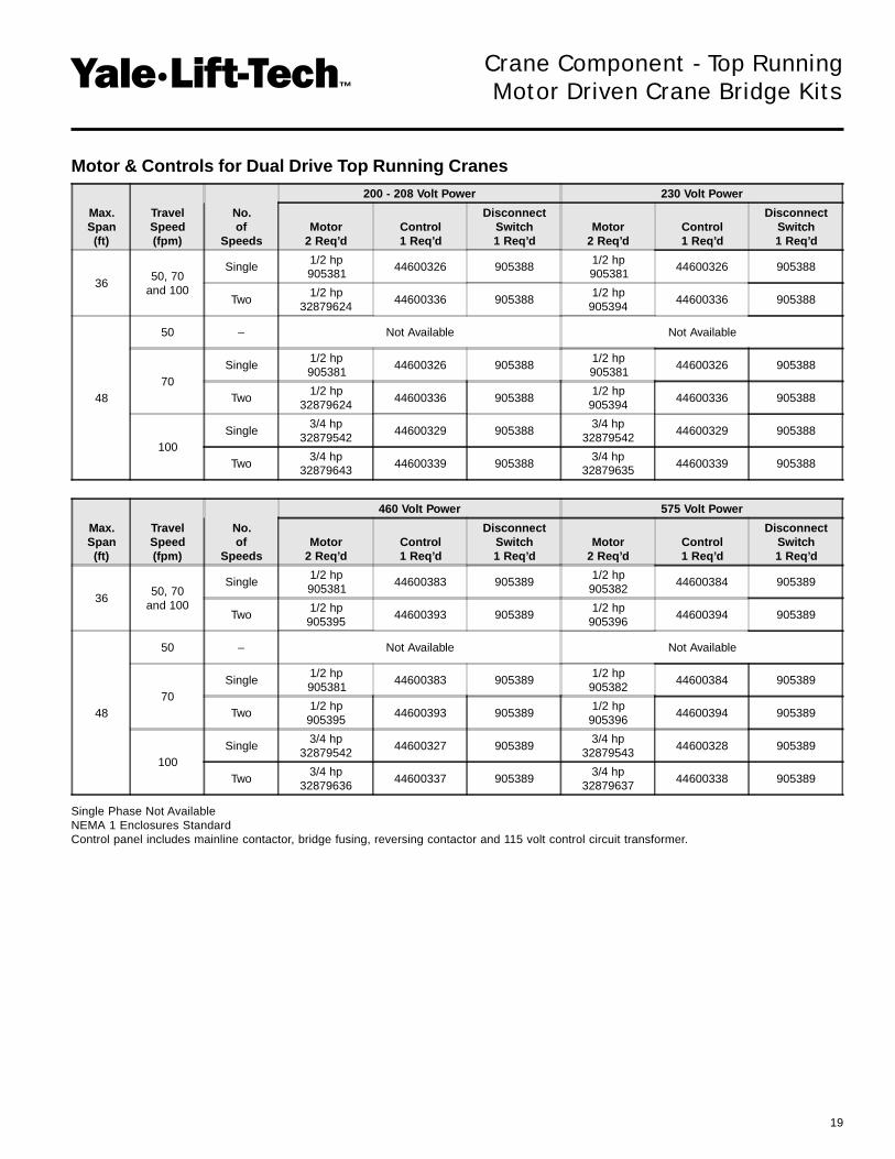
Max.Span(ft)
TravelSpeed(fpm)
No.of
Speeds
460 Volt Power 575 Volt Power
Motor2 Req’d
Control1 Req’d
DisconnectSwitch1 Req’d
Motor2 Req’d
Control1 Req’d
DisconnectSwitch1 Req’d
3650, 70
and 100
Single1/2 hp905381
44600383 9053891/2 hp
90538244600384 905389
Two1/2 hp
90539544600393 905389
1/2 hp905396
44600394 905389
48
50 – Not Available Not Available
70Single
1/2 hp905381
44600383 9053891/2 hp
90538244600384 905389
Two1/2 hp
90539544600393 905389
1/2 hp905396
44600394 905389
100Single
3/4 hp32879542
44600327 9053893/4 hp
3287954344600328 905389
Two3/4 hp
3287963644600337 905389
3/4 hp32879637
44600338 905389
Single Phase Not AvailableNEMA 1 Enclosures StandardControl panel includes mainline contactor, bridge fusing, reversing contactor and 115 volt control circuit transformer.
Crane Component - Top RunningMotor Driven Crane Bridge Kits
Motor & Controls for Dual Drive Top Running Cranes
Max.Span(ft)
TravelSpeed(fpm)
No.of
Speeds
200 - 208 Volt Power 230 Volt Power
Motor2 Req’d
Control1 Req’d
DisconnectSwitch1 Req’d
Motor2 Req’d
Control1 Req’d
DisconnectSwitch1 Req’d
3650, 70
and 100
Single1/2 hp905381
44600326 9053881/2 hp905381
44600326 905388
Two1/2 hp
3287962444600336 905388
1/2 hp905394
44600336 905388
48
50 – Not Available Not Available
70Single
1/2 hp905381
44600326 9053881/2 hp905381
44600326 905388
Two1/2 hp
3287962444600336 905388
1/2 hp905394
44600336 905388
100Single
3/4 hp32879542
44600329 9053883/4 hp
3287954244600329 905388
Two3/4 hp
3287964344600339 905388
3/4 hp32879635
44600339 905388

20
������������™
(**) BEAM SIZES FOR VARIOUS SPANS
SpansTo
(*) RATED LOAD IN TONS OF 2000#
1/4 1/2 1 1-1/2 2 3 4 5
Motor Driven Crane - 54" Wheelbase
10 ft. S 6x12.5 S 6x12.5 S 6x12.5 S 10x25.4 S 10x25.4 S 12x40.8 S 12x40.8 S 12x40.8
12 ft. S 6x12.5 S 6x12.5 S 7x15.3 S 10x25.4 S 12x31.8 S 12x40.8 S 12x40.8 S 18x54.7
14 ft. S 6x12.5 S 6x12.5 S 7x15.3 S 10x25.4 S 12x31.8 S 12x40.8 S 12x40.8 S 18x54.7
16 ft. S 6x12.5 S 7x15.3 S 8x18.4 S 10x25.4 S 12x31.8 S 12x40.8 S 18x54.7 S 18x54.7
18 ft. S 7x15.3 S 8x18.4 S 10x25.4 S 12x31.8 S 12x31.8 S 18x54.7 S 18x54.7 S 20x66
20 ft. S 7x15.3 S 8x18.4 S 10x25.4 S 12x31.8 S 12x40.8 S 18x54.7 S 18x54.7 S 20x66
22 ft. S 8x18.4 S 10x25.4 S 12x31.8 S 12x40.8 S 12x40.8 S 18x54.7 S 20x66 S 20x66
24 ft. S 10x25.4 S 10x25.4 S 12x31.8 S 12x40.8 S 18x54.7 S 20x66 S 20x66 S 24x80
26 ft. S 10x25.4 S 10x25.4 S 12x40.8 S 18x54.7 S 18x54.7 S 20x66 S 18x54.7 w/C 9x13.4 S 24x80
28 ft. S 10x25.4 S 12x31.8 S 12x40.8 S 18x54.7 S 12x40.8 w/C 8x11.5 S 18x54.7 w/C 9x13.4 S 18x54.7 w/C 9x13.4 S 20x66 w/C 9x13.4
30 ft. S 10x25.4 S 12x31.8 S 12x40.8 S 18x54.7 S 12x40.8 w/C 8x11.5 S 18x54.7 w/C 9x13.4 S 18x54.7 w/C 9x13.4 S 20x66 w/C 9x13.4
32 ft. S 12x31.8 S 12x40.8 S 18x54.7 S 12x40.8 w/C 8x11.5 S 15x42.9 w/C 8x11.5 S 18x54.7 w/C 9x13.4 S 18x54.7 w/C 10x15.3 S 20x66 w/C 9x13.4
34 ft. S 12x40.8 S 12x40.8 S 18x54.7 S 15x42.9 w/C 8x11.5 S 15x42.9 w/C 8x11.5 S 18x54.7 w/C 9x13.4 S 20x66 w/C 9x13.4 S 20x66 w/C 9x13.4
36 ft. S 12x40.8 S 12x40.8 S 12x31.8 w/C 9x13.4 S 15x42.9 w/C 8x11.5 S 15x42.9 w/C 8x11.5 S 18x54.7 w/C 20x20.7 S 20x66 w/C 9x13.4 S 20x66 w/C 12x20.7
Bridge Girder Beam Sizes For Top Running Motor Driven CranesAmerican Standard I-Beams and Channel Selections
Crane Component - Top RunningMotor Driven Crane Bridge Kits
* Rated capacity is based on maximum combined hoist and trolley weights of 500 pounds for 1/4, 1/2 and 1 ton hoists: 1100 pounds for 1-1/2 and2 ton hoists; 1600 pounds for 3 and 4 ton hoists; 2000 pounds for 5 ton hoists. Bridge designed in accordance with CMAA Specification No. 74.Use ASTM A36 grade steel, first quality, free of rust and excessive mill scale.
** Beam sizes listed are American Standard I-Beam and Channel sections. Use ASTM A36 grade steel, first quality, free of rust and excessive millscale.

21
������������™
BEAM SIZES FOR VARIOUS SPANS
SpansTo
(*) RATED LOAD IN TONS OF 2000#
1/4 1/2 1 1-1/2 2 3 4 5
Push or Hand Geared Crane - 54" Wheelbase
10 ft. W 6x12 W 6x12 W 8x15 W 10x19 W 12x22 W 10x30 W 14x38 W 18x46
12 ft. W 6x12 W 6x12 W 8x15 W 10x19 W 12x22 W 12x35 W 18x40 W 18x46
14 ft. W 6x12 W 6x12 W 8x15 W 10x19 W 10x26 W 12x35 W 18x40 W 18x46
16 ft. W 6x12 W 8x15 W 8x18 W 10x26 W 14x26 W 14x38 W 16x45 W 16x50
18 ft. W 8x15 W 8x18 W 8x18 W 10x26 W 10x30 W 18x40 W 16x45 W 18x55
20 ft. W 8x15 W 8x18 W 8x21 W 10x26 W 10x30 W 18x40 W 18x46 W 16x57
22 ft. W 8x18 W 8x18 W 10x26 W 10x30 W 14x34 W 12x45 W 16x50 W 16x57
24 ft. W 8x18 W 8x21 W 10x26 W 10x30 W 12x35 W 16x45 W 16x50 W 16x57
26 ft. W 8x21 W 10x22 W 10x30 W 12x35 W 14x38 W 14x48 W 14x53 W 18x60
28 ft. W 10x22 W 10x26 W 10x30 W 14x38 W 12x40 W 14x48 W 16x57 W 18x65
30 ft. W 10x22 W 10x26 W 14x34 W 12x40 W 14x43 W 14x53 W 18x65 W 18x71
32 ft. W 10x26 W 10x30 W 12x35 W 14x43 W 14x48 W 18x60 W 16x67 W 16x77
34 ft. W 10x26 W 12x30 W 14x38 W 14x48 W 14x48 W 18x65 W 16x67 W 16x77
36 ft. W 10x30 W 14x34 W 12x40 W 14x48 W 14x53 W 16x67 W 16x77 W 16x89
Motor Driven Crane - Single Drive - 36" and 54" Wheelbase
10 ft. W 6x12 W 6x12 W 8x15 W 10x19 W 12x22 W 12x35 W 18x40 W 18x46
12 ft. W 6x12 W 6x12 W 8x15 W 10x19 W 10x26 W 12x35 W 18x40 W 18x46
14 ft. W 6x12 W 6x12 W 8x18 W 10x26 W 14x26 W 14x38 W 10x45 W 16x50
16 ft. W 6x12 W 8x15 W 8x18 W 10x26 W 10x30 W 18x40 W 16x45 W 14x53
18 ft. W 8x15 W 8x18 W 8x21 W 10x26 W 10x30 W 18x40 W 18x46 W 16x57
20 ft. W 8x18 W 8x18 W 8x21 W 10x30 W 10x30 W 10x45 W 12x50 W 16x57
22 ft. W 8x18 W 8x21 W 10x26 W 10x30 W 12x35 W 16x45 W 16x50 W 16x57
24 ft. W 8x18 W 8x21 W 10x26 W 14x34 W 14x38 W 14x48 W 14x53 W 18x65
26 ft. W 8x21 W 10x26 W 10x30 W 12x35 W 12x40 W 12x50 W 16x57 W 18x65
28 ft. W 10x22 W 10x26 W 10x33 W 12x40 W 12x40 W 14x53 W 18x65 W 18x71
30 ft. W 10x26 W 10x30 W 12x35 W 12x40 W 12x45 W 14x53 W 16x67 W 14x74
32 ft. W 10x26 W 10x30 W 14x38 W 12x45 W 14x48 W 14x61 W 16x67 W 16x77
34 ft. W 10x30 W 14x34 W 12x40 W 14x48 W 14x53 W 16x67 W 16x67 W 16x89
36 ft. W 10x30 W 12x35 W 12x40 W 14x53 W 14x61 W 16x67 W 16x77 W 16x89
Motor Driven Crane - Dual Drive - 72" Wheelbase
38 ft. W12x35 W12x40 W14x48 W14x61 W16x67 W16x77 W16x89 W18x97
40 ft. W12x40 W12x45 W14x53 W16x67 W16x67 W16x89 W18x86 W21x101
42 ft. W12x40 W14x48 W14x61 W16x67 W16x67 W18x86 W18x97 W21x101
44 ft. W14x43 W14x48 W14x61 W16x67 W16x77 W18x86 W21x101 W21x111
46 ft. W14x48 W14x53 W16x67 W16x77 W18x76 W18x97 W21x101 W21x111
48 ft. W14x53 W14x61 W16x67 W18x76 W18x86 W21x101 W21x111 W21x122
American Standard Wide Flange Beam Selections
* Rated capacity is based on maximum combined hoist and trolley weights of 500 pounds for 1/4, 1/2 and 1 ton hoists: 1100 pounds for 1-1/2 and2 ton hoists; 1600 pounds for 3 and 4 ton hoists; 2000 pounds for 5 ton hoists. Bridge designed in accordance with CMAA Specification No. 74.Use ASTM A36 grade steel, first quality, free of rust and excessive mill scale.
Crane Component - Top RunningMotor Driven Crane Bridge Kits

22
������������™
Beams (Depth) D
6", 7", 8", 10" & 12" 3-1/4"
15", 18" & 20" 4-3/4"
J=7-3/4" + D + 3"
Crane Component - Top RunningMotor Driven Crane Bridge Kits
Single Drive
Dual Drive - 36' Spans*
Beams (Depth) D
6", 7", 8", 10" & 12" 3-1/4"
15", 18" & 20" 4-3/4"
J=7-3/4" + D + 3"
* For spans from 36' up to 48' consult factory.

23
������������™
Top RunningEnd truck frames are steel channel box section weldment for a strong, rigid construction. End truck plates serve as rail sweeps forbridge protection and anti-drop stops, as required by CMAA Specification No. 74. The standard truck wheelbase is 4’-6” or 6'-0",suitable for spans to 36 feet or 48 feet respectively, meeting the CMAA span to wheelbase ratio limit of 8 to 1. Wheels are 8” diameterof high strength ductile iron, with a hardness of 220 BHN. Wheels have cylindrical tread designed for a minimum recommended railof ASCE 20 lbs. Maximum size runway rail for minimum CMAA Specification No. 74 float of ¾” is ASCE 45 lbs. Width between wheelflanges is 2-3/4”. Wheel bearings are lifetime lubricated precision ball bearings. They provide a minimum of 5000 hours performancein accordance with CMAA Specification No. 74. Maximum allowable wheel load (determined in accordance with CMAA SpecificationNo. 74) is 6500 pounds (per pair).
UnderhungThe end truck is a rigid steel weldment, reinforced at the wheel axles and girder connection. The truck is welded of formed channelsides and structural steel plates complete with welded girder pads and end plates forming a rigid “U” shaped structure. The wheelsare solid forged steel and rotate on two sealed lifetime-lubricated ball bearings. The wheels are heat treated with a hardness of 300BHN. The single flange wheels have a compound tread for operation on American Standard I-beam or wide flange beams. Wheeldiameter is 4 inch on 3 ton trucks and 6 ½ inch on 5 ton trucks. Patented track wheels are available for both capacities. The push typeand geared type underhung end trucks are designed in accordance with CMAA Specification No. 74. The maximum wheel load isdetermined in accordance with CMAA Specification No. 74.
Gear ReducersA right-angle, shaft mounted worm drive gear reducer can be mounted at either end of the bridge. The gear reducers can be mountedon either top running or underhung end trucks. Traverse reducer provides stopping motion of the bridge within a distance in feet equalto 10 percent of full load speed in feet per minute (traveling at maximum speed with maximum rated load).
3-Ton 36' Span 3-Ton 48' Span 5-Ton 36' Span 5-Ton 36' Span 5-Ton 48' Span CatalogUnderhung Underhung Underhung Top Running Top Running Number
Traverse Speed 110 fpm 110 fpm 100 fpm 100 fpm 100 fpm 905376Traverse Speed 70 fpm 70 fpm 65 fpm 70 fpm 70 fpm 905377Traverse Speed 55 fpm – 50 fpm 50 fpm – 905378
Cross Shaft SupportThe cross shaft support, with its antifriction lifetime-lubricated bearings, support the cross shaft. For hand geared and single drivemotor driven cranes, cross shafts are required. The cross shafts are to be 1” diameter AISI 1018 cold drawn steel.
Cross Shaft CouplingThe cross shaft couplings connect the cross shaft to the pinion shaft at each end truck, as well as couple sections of cross shaft.
MotorDrive motor is a ½ or a ¾ horsepower, NEMA design 30-minute rated TENV with Class “F” insulation squirrel cage motor. The motoris provided with thermal overload protection as standard, C-faced mounted to the gear reducer. Single speed, two speed, three phase,and single phase motors (½ hp only) are available. Voltages available in single and two speed are 208-230-460-575 volt-3ph-60Hz,Voltages available in single speed only are 115-230 volt-1ph-60 Hz. Consult factory for any other special speeds or voltages that arenot shown.
Control PanelThe control panels include mainline contactor, 115-volt control circuit transformer with fused secondary terminal strip, bridge fusingand reversing contactor in a NEMA 1 enclosure. NEMA 4/12 panels are available as an option.
Fused Disconnect SwitchFused disconnect switch box has positive power disconnect and crane fusing. NEMA 1 enclosure is standard with NEMA 4/12available as an option.
Bridge Brake (optional)Bridge brake is a disc type that is available as an option. The bridge’s standard drive reducer is a worm that will stop the crane withinthe CMAA and OSHA requirements.
Hand Geared & MotorizedCrane Components

24
������������™
Electronic Acceleration Control (optional)The electronic acceleration control is a solid state device for controlling the torque and time of acceleration of the bridge crane. Theelectronic acceleration control provides a more controlled acceleration and is less load sensitive than conventional ballast resistors.
Air Motor Drive Package – Catalog Number 904558 (optional)Air motor drive packages are available in capacities up to 5 tons and spans to 36 feet. They can be mounted on the formed channeltype end trucks that have geared wheels and drive pinions. Only one drive is required. The package includes air motor, gear reducer,control head with pendant throttle and air hose assembly with an 8’drop. Variable traverse speeds from 0-70 fpm are achievable. Filter,lubricator and regulator are recommended options.
Bridge Bumpers (optional)Heavy duty rubber bumpers help cushion bridge end stop impact.
Other Options AvailableVariable Frequency ControlBallast ResistorsThermal Overload RelaysSpark Resistance (Hand-geared and push type trucks)Patented track
Hand Geared & MotorizedCrane Components
Improper application, installation, and use of cranekits can result in personal injury.
TO AVOID INJURY:
DO read, apply and install per assembly manual.
DO install trolley stops.
DO NOT exceed maximum capacity
DO NOT use to lift people or loads over people.
WARNING

Notes

Notes

Notes

Printed in U.S.A. / Copyright 2006 Yale•Lift-Tech division of Columbus McKinnon Corporation No. CS/L-1003-0206
414 West Broadway Ave.P.O. Box 769Muskegon, Michigan 49443-0769
Distributed by Tri-State Equipment Company [email protected]
Tel: (314) 869-7200