Embed Size (px)
Citation preview
Yagi Tun ing & Assembly Data Introduction Your new Antenex Yagi antenna has been designed for accuracy, durability and value. Electrical designs are optimized using the latest in computer aided technology. For fully welded and anodized models, all critical element to boom joints are welded, the entire antenna is anodized, a heavy duty anodized cast mounting kit is included and the antenna is internally matched. This provides for extremely high durability, resistance to corrosion and an accurate radiation pattern. Warning! Use extreme caution when installing this antenna. Electrocution and/or death can occur if this antenna comes in contact with or comes near electric power lines. __________________________________________________________________________400 to 1000 MHz Pre-Assembled & Welded Yagi Antennas The internally matched, fully assembled and welded Yagi antenna for frequencies above 400 MHz is factory tuned to the middle of the operating frequency range. The antenna features broad bandwidth and low VSWR across the band. No further adjustment to the antenna is necessary. It is suggested, however that before permanently mounting the antenna it should be checked for low VSWR. This can be done by temporarily positioning the antenna on a mast at least four (4) feet above the ground and away from surrounding objects. Apply RF power to the antenna and check for resonance. Upon installation of the antenna, after installing the coax to the end of the boom, be sure to relieve the strain on the feed joint. This can be accomplished by looping the coax to the mast, secure the coax to the mast with a nylon tie and then route it down the mast to the fi nal amplifi er.__________________________________________________________________________VHF User-Assembled Yagi Antenna Follow the instructions listed below to assemble your VHF Yagi Antenna:
Assembly Steps 1. Unpack the antenna and locate the following parts: Boom (1-1/4" dia. for fi ve element model, 7/8" dia. for three element model) 3/8" Diameter Elements (Y—3 = three elements, Y—5 = fi ve elements) Gamma Match parts bag Mounting Bracket parts bag
2. To assemble a factory tuned model, locate the 3/8" diameter elements and proceed to step fi ve.
3. Field tunable models are shipped with the 3/8" diameter elements trimmed to the lowest frequency. In order to tune your antenna to another frequency in its range, locate the elements and proceed to step four.
4. Find the proper element dimension chart for your antenna on the next page and trim each element according to your operating frequency. Use care to trim equal lengths from each end of each element as there is a threaded mounting hole at the center. This mounting hole must be at the center of the element after trimming!
5. Insert the elements into their respective locations through the boom starting with R1 (the refl ector el e ment) in the hole closest to the mounting holes. Then insert Dr, D1, etc., in that order. Secure the el e ments with the stainless steel 10-32 hex bolts and #10 lock washers provided. Complete the element installation by inserting the black end caps onto the ends of each element.
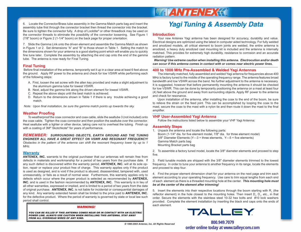
6. Locate the Connector/Brass tube assembly in the Gamma Match parts bag and insert the assembly tube fi rst through the connector bracket then thread the connector into the bracket. Be sure to tighten the connector fully. A drop of Locktite® or other threadlock may be used on the connector threads to eliminate the possibility of the connector loosening. See Figure 1 (7/8" boom) or Figure 2 (1-1/4" boom) on the back page for proper orientation.
7. Slide the Gamma Link onto the driven element and assemble the Gamma Match as shown in Figure 1 or 2. Set dimensions “A” and “B” to those shown in Table 1. Setting the match to the dimensions shown for your antenna is a good starting point which will enable you to quickly fi ne tune later. Complete the assembly by attaching the end cap onto the end of the gamma tube. The antenna is now ready for Final Tuning.
Final Tuning Before fi nal installation of the antenna, tem po rari ly set it up in a clear area at least 6 feet above the ground. Apply RF power to the antenna and check for low VSWR while performing each of the following steps:
A. First, loosen the set screw with the allen key provided and make a slight adjustment to the aluminum gamma tube for lowest VSWR. B. Next, adjust the gamma link along the driven element for lowest VSWR. C. Repeat the above steps until the best match is achieved. D. Return to the dimensions shown in Table 1 if there is any trouble achieving a good match.
Note: Upon fi nal installation, be sure the gamma match points up towards the sky.
Weather Proofi ng To weatherproof the coax connector and coax cable, slide the sealtube 3 (not included) onto the coax cable. Tighten the coax connector and then position the sealtube over the connector. Heat sealtube with a lighter or other device, taking care not to overheat the tubing. Finish up with a coating of 3M® Skotchkote® for years of performance.
REMEMBER: SUR ROUND ING OB JECTS, EARTH GROUND AND THE TUNING EN GI NEER ALL HAVE A GREAT EFFECT ON VSWR AND RES O NANT FRE QUEN CY! Obstacles in the pattern of the antenna can shift the resonant frequency lower by up to 1 MHz.
WarrantyANTENEX, INC. warrants to the original purchaser that our antennas will remain free from defects in ma te ri als and workmanship for a period of two years from the purchase date. If any such defect is discovered within the warranty period, ANTENEX, INC. will at its sole op-tion, repair or replace your product free of charge. This warranty applies only if the product is used as designed, and is void if the product is abused, disassembled, tampered with, used unreasonably, or fails as a result of normal wear. Furthermore, this warranty applies only to defects which occur where the proper product is selected as rec om mend ed by ANTENEX, INC. and is used in the fashion recommended by ANTENEX, INC. This warranty is in lieu of all other warranties, expressed or implied, and is limited to a period of two years from the date of original purchase. ANTENEX, INC. is not liable for incidental or consequential damages of any kind. Any warranty extended herein shall be limited to the price paid to ANTENEX, INC. for the defective product. Where the period of warranty is governed by state or local law such period shall control.
WARNING!
YOU CAN BE KILLED IF THIS ANTENNA COMES NEAR OR IN CONTACT WITH AN ELECTRIC POWER LINE. ALWAYS USE CAUTION WHEN INSTALLING THIS ANTENNA. STAY AWAY FROM ALL OVERHEAD WIRES OF ANY KIND.
© 1990-2003 Antenex, Inc. All Rights Reserved 800.949.7079 order online today at www.talleycom.com

40
39
38
37
36
35
34
33
32
31
30174172170168166164162160158156154152150
40
39
38
37
36
35
34
33
32
31
30174172170168166164162160158156154152150
39
38
37
36
35
34
150148146144142140138136
Y1363 Y1365
Y1503 Y150533
43
42
41
40
R
DD
1
R1
R
D
D D
1
R
1 3-
R
DD
1
R1
40
41
42
43
33
34
35
36
37
38
39
136 138 140 142 144 146 148 150
R
D
D
1
R
1- D3
03/09/95 TB 1050INS1.CAD
220 223 226 229 232 235 238 241 244 247 250
19
20
21
22
23
24
25
26
Y2203
Y2503
Y2205
Y2505
RDD
1
R
1
25
24
23
22
21
20
19
18
17
16
15286283280277274271268265262259256253250
R
DD
1
R
1
18
27
28
15
16
17
18
19
20
21
22
23
24
25
18
23
22
21
20
19
250247244241238235232229226223220
250 253 256 259 262 265 268 271 274 277 280 283 286
R
RD1D
24
25
26
27
28
1
R
1
D
D
R
-D2
-D2
03/09/95 TB 1050INS2.CAD
Gamma Match Silver Series
Phone: 630-351-9007 • Fax: 630-351-9009 • www.antenex.com • N:\Instruction Sheets\2003\yagi1_031403.pdf © 1990-2003 Antenex, Inc. All Rights Reserved
Gamma Match Dimensions (Table 1)Model Freq. Dim "A" Dim "B" Model Freq. Dim "A" Dim "B"Y1363 136 7-5/8" 4" Y2203 220 6-3/4" 3-3/8"Y1365 136 6-7/8" 3" Y2205 220 4-3/8" 1-2"Y1503 150 4-3/8" 2-3/8" Y2503 250 7-5/8" 2-1/4"Y1505 150 4-5/8" 3-5/8" Y2505 250 7-1/4" 2"
6 Element Yagi
R1 D1 D2 D3 D4 D5
R2
D1
R1
All graphs shown in inches
All graphs shown in inches
800.949.7079 order online today at www.talleycom.com