Embed Size (px)
Citation preview

BY HYDROHOIST BOATLIFTS
INSTALLATION MANUAL
US PATENT # 6,422,167 B1
Document Revision: June 21st 2018
800.825.3379 BOATLIFT.COM

INTRODUCTION
At HydroHoist® Marine Group, we take pride in bringing the most advanced, easy to use, minimum mainte-
nance boat lift system to the market today. The installation of this lift is simplified by its lightweight design
and simple operation. In the pages that follow, we will take you step by step through the entire installation pro-
cess, including the lofting and lowering of the boat. We urge you to read this manual before attempting an in-
stallation.
Before you begin…
The HarborHoistTM G1.5 can be assembled easily by 2 people in a single afternoon. Review all the parts, hard-
ware, and required tool listed below to familiarize yourself with the product before you begin to assemble and
don’t forget...safety first. You may contact out Technical Support Team to answer any questions.
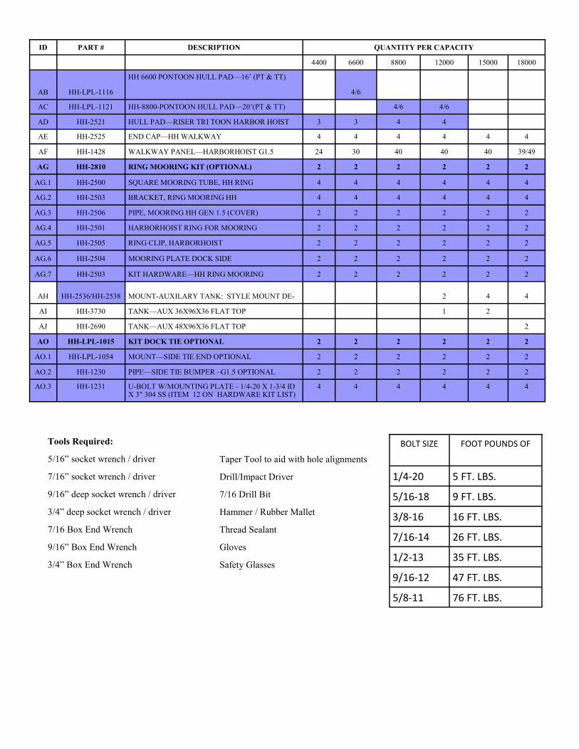
(ITEMS IN BLUE ARE OPTIONAL THERE NEED AND QTY WILL CHANGE WITH LIFT ORDERED)(PT = PONTOON/ TT = TRITOOON)
ID PART # DESCRIPTION QUANTITY PER CAPACITY
4400 6600 8800 12000 15000 18000
A HH-2601 TOP PLATE—HH ALUMINUM GEN 1 MOD 4 6 8 8 8 8
B HH-LPL-1024 GASKET—TOP HARBOR HOIST 4 6 8 8 8 8
C HH-LPL-1025 STRAP PLATE—ALUM. HH 8 12 16 16 16 16
D HH-LPL-1040 CHANNEL—SUPPORT HH 8 12 16 16 16 16
E HH-LPL-1027 GASKET—BOTTOM—HARBORHOIST 8 12 16 16 16 16
F HH-3000 TANK—HARBOR HOIST G1.5 4 6 8 8 8 8
G HH-LPL-1028 GASKET - UNDERNEATH - HARBORHOIST 8 12 16 16 16 16
H HH-LPL-1033 TUBE—SPACER, 3X3 ALUMINUM 4 4 4 4 4 4
I HH-LPL-1034 BEAM—48IN SPAN—ALUM. HH. 4 6 6 6 6
J HH-2519 BEAM—84IN SPAN—ALUM HH 2
K HH-2515 SUPPORT—WALKWAY HARBORHOIST 6 8 8 8 8
L HH-2518 SUPPORT—WALKWAY HARBORHOIST 4400 4
M HH-LPL-1018 I BEAM-84IN 4 6 8 8
AM HH-LPL-1036 108” BEAM (OPTIONAL ON V-HULL STD ON PT 4 6 8 8 8 8
AN HH-4310 100” V-FRAME (OPTIONAL ON 44-88 STD ON 12- 4 6 8 8 8 8
O HH-2912 HULL PADS, ALUMINUM 12FT,HARBOR HOIST 2
P HH-2916 HULL PADS, ALUMINUM 16FT, HARBORHOIST 2
Q HH-2920 HULL PADS, ALUMINUM 20FT, HARBORHOIST 2 2 2 2
R HH-LPL-1013 BRACKET - HULL SUPPORT - STD. HH 8 12 16 16 16 16
S HH-2740 CONTROL—HARBORHOIST GEN 1.5 4V 1 1 1
T HH-2750 CONTROL—HARBOR HOIST GEN 1.5 5V 1 1 1
U 3072516 HOSE - RUBBER 1-1/4 in. ID X 50 ft. - CUT 1
V 3072510 HOSE - RUBBER 1-1/4 in. ID X 75 ft. - CUT 1
W 3072517 HOSE - RUBBER 1-1/4 in. ID X 100 ft. - CUT 1 1 1 1
X HH-2517 CONTROL—STAND HH AUTOMATIC 1 1 1 1 1 1
Z HH-LPL-1001 BRACKET—PONTOON HH (PT;TT) 6 6 8 8 8 8
AA HH-LPL-1112 HH 4400-PONTOON HULL PAD—12’ 4/6
ID PART # DESCRIPTION QUANTITY PER CAPACITY
4400 6600 8800 12000 15000 18000
AB HH-LPL-1116
HH 6600 PONTOON HULL PAD—16’ (PT & TT)
4/6
AC HH-LPL-1121 HH-8800-PONTOON HULL PAD—20’(PT & TT) 4/6 4/6
AD HH-2521 HULL PAD—RISER TRI TOON HARBOR HOIST 3 3 4 4
AE HH-2525 END CAP—HH WALKWAY 4 4 4 4 4 4
AF HH-1428 WALKWAY PANEL—HARBORHOIST G1.5 24 30 40 40 40 39/49
AG HH-2810 RING MOORING KIT (OPTIONAL) 2 2 2 2 2 2
AG.1 HH-2500 SQUARE MOORING TUBE, HH RING 4 4 4 4 4 4
AG.2 HH-2503 BRACKET, RING MOORING HH 4 4 4 4 4 4
AG.3 HH-2506 PIPE, MOORING HH GEN 1.5 (COVER) 2 2 2 2 2 2
AG.4 HH-2501 HARBORHOIST RING FOR MOORING 2 2 2 2 2 2
AG.5 HH-2505 RING CLIP, HARBORHOIST 2 2 2 2 2 2
AG.6 HH-2504 MOORING PLATE DOCK SIDE 2 2 2 2 2 2
AG.7 HH-2503 KIT HARDWARE—HH RING MOORING 2 2 2 2 2 2
AH HH-2536/HH-2538 MOUNT-AUXILARY TANK: STYLE MOUNT DE- 2 4 4
AI HH-3730 TANK—AUX 36X96X36 FLAT TOP 1 2
AJ HH-2690 TANK—AUX 48X96X36 FLAT TOP 2
AO HH-LPL-1015 KIT DOCK TIE OPTIONAL 2 2 2 2 2 2
AO.1 HH-LPL-1054 MOUNT—SIDE TIE END OPTIONAL 2 2 2 2 2 2
AO.2 HH-1230 PIPE—SIDE TIE BUMPER –G1.5 OPTIONAL 2 2 2 2 2 2
AO.3 HH-1231 U-BOLT W/MOUNTING PLATE - 1/4-20 X 1-3/4 ID X 3" 304 SS (ITEM 12 ON HARDWARE KIT LIST)
4 4 4 4 4 4
Taper Tool to aid with hole alignments
Drill/Impact Driver
7/16 Drill Bit
Hammer / Rubber Mallet
Thread Sealant
Gloves
Safety Glasses
Tools Required:
5/16” socket wrench / driver
7/16” socket wrench / driver
9/16” deep socket wrench / driver
3/4” deep socket wrench / driver
7/16 Box End Wrench
9/16” Box End Wrench
3/4” Box End Wrench
BOLT SIZE FOOT POUNDS OF
1/4-20 5 FT. LBS.
5/16-18 9 FT. LBS.
3/8-16 16 FT. LBS.
7/16-14 26 FT. LBS.
1/2-13 35 FT. LBS.
9/16-12 47 FT. LBS.
5/8-11 76 FT. LBS.

2ID PART # DESCRIPTION QUANTITY PER CAPACITY
4400 6600 8800 12000 15000 18000
1 HH-2650 KIT BOX—HH G1.5 TANK SET 2 3 4 4 4 4
1.1 HH-LPL-1503 U-BOLT—.375 X 3 X 5 SS 16 24 32 32 32 32
1.2 HH-LPL-1504 U-BOLT—.375 X 3 X 6 SS 16 24 32 32 32 32
1.3 HH-LPL-1006 BOLT—5 IN FLAT HEAD SS 16 24 32 32 32 32
1.4 HH-LPL-1501 BOLT—HX HEAD—1/4-20X1.5” SS 16 24 32 32 32 32
1.5 HH-LPL-1508 WASHER—FLAT—1/2 X 2 OD SS 16 24 32 32 32 32
1.6 2090216 WASHER—FLAT—1/4” SS 32 48 64 64 64 64
1.7 HH-LPL-1505 WASHER—LOCK 3/8 SS 64 96 128 128 128 128
1.8 HH-1916 WASHER—LOCK 1/2” SCREW SIZE 18-8 SS 4 6 8 8 8 8
1.9 HH-2603 NUT—3/8-16 BRASS 64 96 128 128 128 128
1.10 HH-2100 NUT, 1/2-13 BRASS NYLOCK 16 24 32 32 32 32
1.11 HH-1926 NUT—HEX 1/2—13 BRASS 20 30 40 40 40 40
1.12 HH-LPL-1502 NUT—1/4-20—SS NYLOCK 16 24 32 32 32 32
1.13 HH-2602 LIFTING RING—1.5 X 4 STAINLESS STEEL 4 6 8 8 8 8
1.14 HH-1016 STUB TUBE ASSEMBLY HH G2 4 6 8 8 8 8
1.15 HH-LPL-1031 BUSHING—NYLON—HH TANK 8 12 16 16 16 16
1.16 2090242 WASHER—FLT—3/8” SS 32 48 64 64 64 64
2 HH-2660 KIT HARDWARE HULL PAD TANK SET 2 3 4 4 4 4
3 HH-2689 KIT HARDWARE HOSE CLAMPS 4400 1
3.1 2090907 CLAMP—HOSE—#24 GEAR—SS300 8
4 HH-2687 KIT HARDWARE HOSE CLAMPS 6600 1
4.1 2090907 CLAMP—HOSE—#24 GEAR—SS300 16
4.2 2093005 TEE - 1 1/4—NYLON HOSE INSERT BARBED 2
5 HH-2685 KIT HARDWARE HOSE CLAMPS 8800 1 1 1 1
5.1 2090907 CLAMP—HOSE—#24 GEAR—SS300 24 24 24 24
5.2 2093005 TEE - 1 1/4—NYLON HOSE INSERT BARBED 4 4 4 4
6 HH-2655 KIT HARDWARE CONTROL MOUNT G1.5 1 1 1 1 1 1
6.1 HH-1913 BOLT CARRIAGE 1/2-13 X 1.5 SS 4 4 4 4 4 4
6.2 HH-2509 BOLT 1/4-20 X 1IN SS HHCS 4 4 4 4 4 4
6.3 HH-1971 SCREW—#12-24 X 3/4 SS 18-8 8 8 8 8 8 8
6.4 HH-1916 WASHER—LOCK 1/2” SCREW 18-8 SS 4 4 4 4 4 4
6.5 HH-1926 NUT—HEX 1/2-13 BRASS 4 4 4 4 4 4
6.6 HH-2508 WASHER—LOCK 1/4” SS 4 4 4 4 4 4
6.7 HH-1972 WASHER—LOCK #12 18-8 SS 8 8 8 8 8 8
6.8 HH-1973 NUT—#12-24 HEX HEAD 18-8 SS 8 8 8 8 8 8
7 HH-2675 KIT, HARDWARE, PONTOON (PER TANK SET) 3 3 4 4 4 4
7.1 HH-1942 CARRIAGE BOLT-1/4-20 X 2 1/4 SS 12 12 16 16 16 16

ID PART # DESCRIPTION QUANTITY PER CAPACITY
4400 6600 8800 12000 15000 18000
7 HH-2675 KIT, HARDWARE, PONTOON (PER TANK SET) (PT-TT) 3 3 4 4 4 4
7.1 HH-1942 CARRIAGE BOLT-1/4-20 X 2 1/4 SS 12 12 16 16 16 16
7.2 HH-2508 WASHER, LOCK 1/4” SS 12 12 16 16 16 16
7.3 HH-1941 NUT, 1/4-20 STAINLESS STEEL 12 12 16 16 16 16
8 HH-2656 KIT—HARDWARE TRITOON (SINGLE BRACKET) (TT) 3 3 4 4
8.1 HH-2604 BOLT—1/2-13 X 1.5 SS 12 12 16 16
8.2 HH-1916 WASHER—LOCK 1/2” SCREW 18-8 SS 12 12 16 16
8.3 HH-1926 NUT—HEX 1/2-13—BRASS 12 12 16 16
9 HH-2503 KIT, HARDWARE HARBORHOIST RING MOORING 2 2 2 2 2 2
9.1 HH-1902 BOLT—1/2-13 X 4 SS HHG2 16 16 16 16 16 16
9.2 HH-1930 BOLT—CARR—1/2-13 X 3.5 18-8 SS 4 4 4 4 4 4
9.3 HH-1916 WASHER—LOCK 1/2” SCREW 18-8 SS 20 20 20 20 20 20
9.4 HH-1926 NUT—HEX 1/2-13 BRASS 20 20 20 20 20 20
10 HH-2672 HARDWARE KIT—AUX. TANK (STRAIGHT FRAME) 1 2
10.1 HH-1946 BOLT—CARR 5/16-18 X 2.75 SS 8 16
10.2 HH-1961 BOLT—CARR 5/16-18 X 1.25 SS 12 24
10.3 HH-1947 WASHER—FENDER 5/16IN ID X 2IN OD SS 16 32
10.4 HH-1948 WASHER—LOCK 5/16 SS 20 40
10.5 HH-1949 NUT—5/16-18—BRASS 20 40
10.6 HH-1962 CLAMP—HARBORHOIST AUX TANK SS 12 24
11 HH-2668 KIT—HARDWARE HULL PAD ALUMINUM 2 3 4 4 4 4
11.1 HH-LPL-1504 U-BOLT—.375X3X6 SS 8 12 16 16 16 16
11.2 HH-2607 BOLT—3/8-16 X 4 SS 8 12 16 16 16 16
11.3 HH-2606 WASHER—FLAT –3/8 SS 8 12 16 16 16 16
11.4 HH-LPL-1505 WASHER– LOCK—3/8 SS 24 36 48 48 48 48
11.5 HH-2603 NUT—3/8-16 BRASS 24 36 48 48 48 48
12 HH-1231 U-BOLT W/MOUNTING PLATE - 1/4-20 X 1-3/4 ID X 3" 304 SS 4 4 4 4 4 4
13 HH-2673 AUX. TANK KIT –V FRAME OPTIONAL 1 2 2
13.1 HH-1944 BOLT-CARR 5/16-18 X 4 18-8 SS 12 24 24
13.2 HH-1946 BOLT-CARR 5/16-18 X 2.75 18-8 SS 6 12 12
13.3 HH-1949 NUT - 5/16-18 - BRASS 18 36 36
13.4 HH-1947 WASHER - FENDER 5/16IN ID X 2IN OD SS 12 24 24
13.5 HH-1948 WASHER – LOCK 5/16 SS 18 36 36
13.6 HH-2539 PLATE - AUX. TANK CONNEECTION HARBORHOIST 6 12 12

STEP 1: STRAP ASSEMBLY— (Repeat this step for each tanks supplied)
STEP 2: ATTACH CHANNEL SUPPORTS TO STRAP ASSEMBLY
Parts Required (Per Tank)
[A] Top Plate x1
[B] Top Gasket x1
[C] Strap Plate x2
Hardware Required
1 HW Tank Set Kit
1.1 U-Bolt 3/8-16 x 3 x 5 x4
1.4 Bolt—Hex 1/4-20 x 1.5 x4
1.6 Washer-Flat 1/4” x8
1.8 Washer—Lock 1/2” 18-8 SS x1
1.11 Nut—Hex 1/2-13 Brass x1
1.12 Nut—1/4-20 SS Nylock x4
1.13 Lifting Ring—1.5 x 4 SS x1
1.12
1) Attach B to A using 1/4-20 x 1.5” bolts,
2 1/4” flat washers per bolt, and 1/4-
20 Nylocks
2) Insert 5” U-Bolts through C and A. (U-
Bolts become captured once this as-
sembly is placed on the tank, Optional-
ly you can put the washers and nuts
from step 5, instruction 3, on the U-
bolts to help retain them)
Parts Required (Per Tank)
[D] Channel Support x1
[E] Bottom Gasket x1
Hardware Required
1 HW Tank Set Kit
1.2 U-Bolt 3/8-16 x 3 x 6 x4
1.3 Bolt—5 IN Flat Head SS x4
1.11 Nut—Hex 1/2-13 Brass x1
1.15 Bushing—Nylon—HH Tank x4
D
E
1.2
1.3
1.11
1.15
1) Attach D to E using the 5” flat head SS bolts,
nylon bushings, and 1/2-13 Brass nuts. Be
sure to capture the Strap assembly between
the two parts as shown.
2) Place the U bolts in place as shown (the U will
be in the slot). Optional: You can loosely
attach the hardware from step 6 instruction 3
on now to help retain the U-Bolts.
A
B
C
1.1
1.4
1.6
1.6
1.13
1.8
1.11
1.12

STEP 3: ATTACH TANK STRAPS TO TANKS
STEP 4: CONNECT STUB TUBES
Parts Required (per Tank)
[F] Tank—HH G1.5 x1
[F] Gasket—Underneath—HH x2
Hardware Required
1 HW Tank Set Kit
1.5 Washer-Flat-1/2X2 OD SS x4
1.9 Nut, 1/2-13 Brass Nylock x4
1) Place the assembly from the previous step on top of the
tank with the straps placed in the recesses along the
inside of the tank top. Push the top plate and gasket
down as tight as you can get it. (depending on the tem-
perature you may not get the gasket to sit flush with
the top of the tank) Also be sure to push the channel
support / Bottom Gasket down as tight as you can get
them as well.
2) Roll the tanks on their back, or lift them in the air if you
have that availability and install the underneath gasket
(rounded side toward the top of the tank) with 2 ea.
1/2”x2”OD Washers and 1/2-13 Brass Nylock nuts per
strap.
G
1.5 1.9 F
Tank shown on back as indicated in direction 2
1) Apply thread sealant to the stub tube threads (TFE PASTE, WHITE
SLOW SETTING IS RECOMMENDED)
2) Screw stub tube into tank, as the threads start to tighten up start
looking for the direction you want the hose to point so that you
can determine if you can turn the stub another full turn to reach
that position or not. You do not want to overshoot the position as
backing the stub tube off could result in a leaking fitting.
3) Attach Hose ends to the stub tubes, with a hose clamp. Make sure
elbows and hoses are routed the correct directions (4 tank—
toward center of lift / 6 Tank—Front 4 tanks to the Rear, Rear 2
toward the front / 8 Tank—Front 2 tanks per side towards each
other, and Rear 2 tanks also toward each other). Routing and
length can be found later in this manual (Step 12). Hose and hose
1.14
Parts Required (4400/6600/8800 & Up)
[U/V/W] Hose—Cut 50/75/100 ft.
Hardware Required (4400/6600/8800 & Up)
1 Kit Box HHG1.5 Tank Set x2/3/4
1.14 Stub Tube Assembly x4/6/8
3/4/5 Hardware Hose Clamps x1/1/1
3/4/5.1 Hose Clamp #24 x4/6/8
STUB TUBE
NOTE: FOR DEEP V-HULLS THAT REQUIRE MORE WATER DEPTH, (TYPICALLY 8800 & UP) STUB
TUBE ASSEMBLY MAY NEED TO BE SHORTENED . TANK SET1 (BOW TANKS) ARE NEVER SHORT-
ENED. FROM THE 2ND TANK SET BACK, YOU CAN SHORTEN TUBES AS FOLLOWS ON CHART.
M
N
1.7
1.9
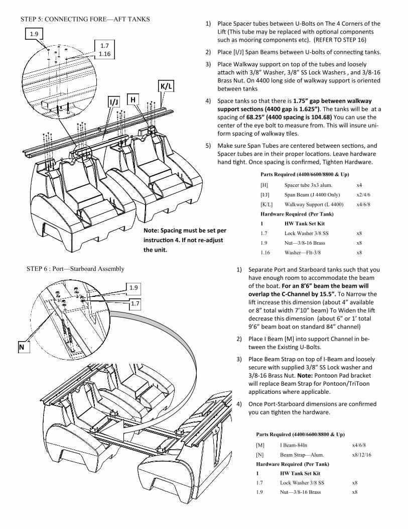
STEP 6 : Port—Starboard Assembly
1) Separate Port and Starboard tanks such that you have enough room to accommodate the beam of the boat. For an 8’6” beam the beam will overlap the C-Channel by 15.5”. To Narrow the lift increase this dimension (about 4” available or 8” total width 7’10” beam) To Widen the lift decrease this dimension (about 6” or 1’ total 9’6” beam boat on standard 84” channel)
2) Place I Beam [M] into support Channel in be-tween the Existing U-Bolts.
3) Place Beam Strap on top of I-Beam and loosely secure with supplied 3/8” SS Lock washer and 3/8-16 Brass Nut. Note: Pontoon Pad bracket will replace Beam Strap for Pontoon/TriToon applications where applicable.
4) Once Port-Starboard dimensions are confirmed you can tighten the hardware.
Parts Required (4400/6600/8800 & Up)
[M] I Beam-84In x4/6/8
[N] Beam Strap—Alum. x8/12/16
Hardware Required (Per Tank)
1 HW Tank Set Kit
1.7 Lock Washer 3/8 SS x8
1.9 Nut—3/8-16 Brass x8
STEP 5: CONNECTING FORE—AFT TANKS
1) Place Spacer tubes between U-Bolts on The 4 Corners of the Lift (This tube may be replaced with optional components such as mooring components etc). (REFER TO STEP 16)
2) Place [I/J] Span Beams between U-bolts of connecting tanks.
3) Place Walkway support on top of the tubes and loosely attach with 3/8” Washer, 3/8” SS Lock Washers , and 3/8-16 Brass Nut. On 4400 long side of walkway support is oriented between tanks
4) Space tanks so that there is 1.75” gap between walkway support sections (4400 gap is 1.625”). The tanks will be at a spacing of 68.25” (4400 spacing is 104.68) You can use the center of the eye bolt to measure from. This will insure uni-form spacing of walkway tiles.
5) Make sure Span Tubes are centered between sections, and Spacer tubes are in their proper locations. Leave hardware hand tight. Once spacing is confirmed, Tighten Hardware.
Parts Required (4400/6600/8800 & Up)
[H] Spacer tube 3x3 alum. x4
[I/J] Span Beam (J 4400 Only) x2/4/6
[K/L] Walkway Support (L 4400) x4/6/8
Hardware Required (Per Tank)
1 HW Tank Set Kit
1.7 Lock Washer 3/8 SS x8
1.9 Nut—3/8-16 Brass x8
1.16 Washer—Flt-3/8 x8
H I/J
K/L
1.7 1.16
1.9
Note: Spacing must be set per
instruction 4. If not re-adjust
the unit.
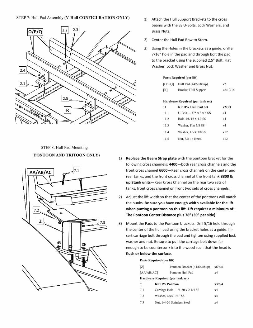
STEP 7: Hull Pad Assembly (V-Hull CONFIGURATION ONLY) 1) Attach the Hull Support Brackets to the cross
beams with the SS U-Bolts, Lock Washers, and
Brass Nuts.
2) Center the Hull Pad Bow to Stern.
3) Using the Holes in the brackets as a guide, drill a
7/16” hole in the pad and through bolt the pad
to the bracket using the supplied 2.5” Bolt, Flat
Washer, Lock Washer and Brass Nut.
Parts Required (per lift)
[O/P/Q] Hull Pad (44/66/88up) x2
[R] Bracket Hull Support x8/12/16
Hardware Required (per tank set)
11 Kit HW Hull Pad Set x2/3/4
11.1 U-Bolt—.375 x 3 x 6 SS x4
11.2 Bolt, 3/8-16 x 4.0 SS x4
11.3 Washer, Flat 3/8 SS x4
11.4 Washer, Lock 3/8 SS x12
11.5 Nut, 3/8-16 Brass x12
O/P/Q
R
2.2 2.3
2.1
2.5
2.4
1) Replace the Beam Strap plate with the pontoon bracket for the
following cross channels: 4400—both rear cross channels and the
front cross channel 6600—Rear cross channels on the center and
rear tanks, and the front cross channel of the front tank 8800 &
up 8tank units—Rear Cross Channel on the rear two sets of
tanks, front cross channel on front two sets of cross channels.
2) Adjust the lift width so that the center of the pontoons will match
the bunks. Be sure you have enough width available for the lift
when putting a pontoon on this lift. Lift requires a minimum of:
The Pontoon Center Distance plus 78” (39” per side)
3) Mount the Pads to the Pontoon brackets. Drill 5/16 hole through
the center of the hull pad using the bracket holes as a guide. In-
sert carriage bolt through the pad and tighten using supplied lock
washer and nut. Be sure to pull the carriage bolt down far
enough to be countersunk into the wood such that the head is
flush or below the surface.
Parts Required (per lift)
[Z] Pontoon Bracket (44/66/88up) x6/6/8
[AA/AB/AC] Pontoon Hull Pad x4
Hardware Required (per tank set)
7 Kit HW Pontoon x3/3/4
7.1 Carriage Bolt—1/4-20 x 2 1/4 SS x4
7.2 Washer, Lock 1/4” SS x4
7.3 Nut, 1/4-20 Stainless Steel x4
Z
AA/AB/AC
7.2
7.1
7.3
STEP 8: Hull Pad Mounting
(PONTOON AND TRITOON ONLY)

STEP 9: Hull Pad Assembly
(TRITOON ONLY)
1) Follow the steps for a pontoon for the outside tubes
2) Determine if there is any offset for the Center tube. For no offset
the distance from the I-beam to the top edge of the V is approx.
7.62” (measure from the I-beam to a point on the pontoon brack-
et and set the tritoon bracket at the same height, adjust as need-
ed for offsets)
3) Place the clamps on either side of the riser tube and bolt togeth-
er with the provided hardware. Tighten just enough to provide
enough friction to hold the riser in place. Make any additional
adjustments needed
4) Tighten the clamp bolts and install the Hull Pads as described in
Step 8 Instruction 3 for the pontoon Pads.
Parts Required (per lift)
[AD] Tritoon Riser (44/66/88up) x3/3/4
[AE] Bracket Clamp Riser (44/66/88) x6/6/8
[AA/AB/AC] Pontoon Hull Pad x2
Hardware Required (per tank set)
7 Kit HW Pontoon x3/3/4
7.1 Carriage Bolt—1/4-20 x 2 1/4 SS x4
7.2 Washer, Lock 1/4” SS x4
7.3 Nut, 1/4-20 Stainless Steel x4
8 Kit HW Tritoon x3/4
8.1 Bolt—1/2-13 x 1.5 SS x4
8.2 Washer—Lock 1/2” 18-8 SS x4
8.3 Nut—Hex 1/2-13—Brass x4
Top Edge of V
AD
AE
AA/AB/AC 7.1
7.2
7.3
8.1
8.2
8.3
ADDITIONAL HULL PAD INFORMATION—
BUNK VALUES (SEPERATION DISTANCES MEASURED INSIDE TO INSIDE OF RECTANGULAR TUBE, Left section of chart shows pad separation and max dead rise angle to maintain 1” minimum clearance listed top to bottom. The Right section lists dead rise angles (in 5 degree increments) from left to right. Looking down the columns lists the clearance values for the Pad separation listed at the Far Left of the chart. Place the hull pads as wide as possible and still have clearance between the hull and I-beam. Be sure to check the boat, boat trailer, or consult the boat manufacturer to insure the location you choose is clear of any underwater obstructions such as speedometer sensors, water pickups, Fins, etc. The hull pads can be placed on the lift such that the front is narrower than the rear if needed, however be sure that if you need to do this the hull pad does not cross a strake or other feature on the hull that would result in a concentrated loading condition. The chart above is based on the dead rise angle and separation distance and is provided as a starting point only.

STEP 10: Control Stand Mounting—
1) Determine where you where on the walkway you want to mount the control (For best leveling it is recommend-ed to locate the control as near to the center of the lift as possible, although it can be mounted at other locations along the walkway if needed). For most lifts the control will be mounted at one end of a walkway section in be-tween two tanks, fot the 6600 it typically will be in the middle of the center tank walkway. It can be mounted either Port or Starboard side.
2) Set stand on the walkway support member. Place Car-riage bolts (6.1) through the base of Control Stand and through the holes in the Walkway support. Secure with a lock washer, and Brass nut. The carriage bolts can be inserted from either the top or bottom, however a more finished look is achieved when the carriage bolt is on the top side of the control stand. Use this orientation when possible.
Parts Required (4400/6600/8800 up)
[X] Control Stand HH Auto
Hardware Required
6 Kit HW Control Mount x1
6.1 Bolt Carriage 1/2-13 x 1.5 x4
6.4 Washer Lock 1/2” 18-8 SS x4
6.5 Nut—Hex 1/2-13 Brass x4
X
6.1
6.4
6.5
STEP 11 CONTROL MOUNTING
Parts Required (4400/66600/8800/12000/15000/18000)
[S] Control—HH G1.5 4 valve x1/1/1/0/0/0
[T] Control—HH G1.5 5 valve x0/0/0/1/1/1
Hardware Required:
6 Kit HW Control Mount G1.5
6.2 Bolt—1/4-20 x 1 SS HHCS x4
6.6 Washer—Lock 1/4” SS x4
1) Attach the Control unit [S/T] to the Control
Stand using the supplied 1/4-20 x 1” SS Bolts
(6.6) and 1/4” SS Lock Washers (6.7).
The control you receive will depend on the size of
the lift ordered. The 4400/6600/8800 will come with
the 4 Valve Control [S] and the 1200/15000/18000
will come standard with the 5 valve Control [T]

STEP 12 TANK PLUMBING—
Rear Port
Rear Starboard
Exhaust
Front Starboard
Front Port
Parts Required (4400/66600/8800 &up)
[U/V/W] Hose (50/75/100 ft) x1/1/1
Hardware Required:
3/4/5 Hardware Hose Clamps x1/1/1
3/4/5.1 Hose Clamp—#24 x4/10/16
4/5.2 Tee—1/1/4” Nylon Hose Barb x0/2/4
Front tanks—4 and 6 tank units: Connect Hos-
es from stub tubes to corresponding Control con-
nection (Front Port / Front Starboard) with sup-
plied Hose Clamps (3.1/4.1). 8 Tank units: Con-
nect Hoses from front 2 tanks of each side to a
Tee (located between the 2 tanks) using the sup-
plied hose clamps (5.1).Attach another length of
hose to the Tees and follow the routing in the
diagrams to connect the hoses to corresponding
connections on the Control (Front Port / Front
Starboard). Rear tanks—4 Tank units: Same
process as Front to Control connections (Rear
Port / Rear Starboard) 6 and 8 Tank Units:
Same process as 8 Tank Front except using the 2
rear tanks on each side and connecting to Control
Connections Rear Port / Rear Starboard.
5 Valve
Rear Port
Rear Starboard
Exhaust
Front Starboard
Front Port
Auxiliary
Front tanks—Connect Hoses from front 2 tanks
of each side to a Tee (located between the 2
tanks) using the supplied hose clamps
(5.1).Attach another length of hose to the Tees
and follow the routing in the diagrams to connect
the hoses to corresponding connections on the
Control (Front Port / Front Starboard).
Rear tanks—Same process as the front except
using the 2 rear tanks on each side and connect-
ing to Control Connections Rear Port / Rear Star-
board.
Auxiliary Tank(s) - For a single Auxiliary tank,
Connect the hose from the tank to the Auxiliary
port on the control. For dual Auxiliary tanks,
connect the two tanks together using one of the
supplied tees. Once that is done, connect the teed
tanks to the Auxiliary port on the control follow-
ing the routing diagrams.
4 Valve

STEP 12 ROUTING DIAGRAMS—
18’ 18’
7’ 7’
4 Tank Hose Routing
7’
21’ 22’
9’ 2’-9” 2’-9” T
2’-9” 2’-9’ T
6 Tank Hose Routing

STEP 14—Walkway Pads
STEP 13—walkway end caps 1) Place End Cap on walkway ends and using the
supplied hardware to attach the cover plate to
the walkway, the tabs on the top side should
extend above the top of the walkway support.
Parts Required
[AE] End Cap—HH Walkway x4
Hardware Required:
6 Kit HW Control Mount x1
6.3 Screw-#12-24 X 3/4 SS 18-8 x8
6.7 Washer—Lock #12 18-8 SS x8
6.8 Nut—#12-24 HH 18-8 SS x8
AE
6.3
6.7 6.8
Parts Required (4/6/8 tank)
[AF] Walkway Panel — HarborHoist G1.5 x23/29/39
AF 1) Snap the walkway panel over the Walkway
support making sure to align the locks with
the recesses in the support. For the end pieces
make sure the end cap tabs align with the slot
on the underside of the panel. The tabs will
lock in to the slot when properly assembled.
Locking tab properly aligned
with support recess
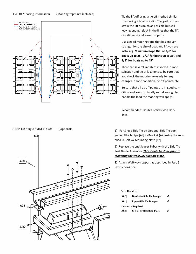
Tie Off Mooring information — (Mooring ropes not included)
STEP 16: Single Sided Tie Off — (Optional)
Parts Required
[A02] Bracket—Side Tie Bumper x2
[A01] Pipe—Side Tie Bumper x2
Hardware Required
[A03] U-Bolt w/Mounting Plate x4
Tie the lift off using a tie off method similar
to mooring a boat in a slip. The goal is to re-
strain the lift as much as possible but still
leaving enough slack in the lines that the lift
can still raise and lower properly.
Use a good mooring rope that has enough
strength for the size of boat and lift you are
installing. Minimum Rope Dia. of 3/8” for
boats up to 25’, 1/2” for boats up to 35’, and
5/8” for boats up to 45’.
There are several variables involved in rope
selection and tie of locations so be sure that
you check the mooring regularly for any
changes in rope condition, tie off points, etc.
Be sure that all tie off points are in good con-
dition and are structurally sound enough to
handle the load the mooring will apply.
Recommended: Double Braid Nylon Dock
lines.
1) For Single Side Tie off Optional Side Tie post
guide: Attach pipe [AL] to Bracket {AK} using the sup-
plied U-Bolt w/ Mounting plate [12]
2) Replace the end Spacer Tubes with the Side Tie
Post Guide Assembly. This should be done prior to
mounting the walkway support plate.
3) Attach Walkway support as described in Step 5
Instructions 3-5.
A01
A02
A03

Parts Required (per Mooring Pole)
AG Ring Mooring Kit x1
AG.1 Square Mooring Tube x2
AG.2 Bracket, Ring Mooring x2
AG.3 Pipe (cover) x1
AG.4 Ring for Mooring x1
AG.6 Dock Side Mooring Plate x1
Hardware Required
9 Hardware Kit Ring Mooring x1
9.1 1/2-13 x 4 SS Bolt x8
9.2 1/2-13 x 3.5 SS Carriage Bolt x2
9.3 1/2” Lock Washer x10
9.4 1/2” Hex Nut Brass x10
STEP 17: Ring Mooring— (Optional)
1) Slide Cover (AG.3) over Sq. Mooring Tube (AG.1)
2) Connect bracket (AG.2) to both Sq. Mooring tubes (AG.1) tubes at one end. This will require 4 1/2”-13 bolts, 4 lock washers, and 4 brass nuts.
3) Slide the mooring ring (AG.4) over the tube with the cover on it.
4) Attach second bracket (AG.2) as you did in step 2.
5) Attach the Dock Side Mooring Plate (AG.6) as shown using the supplied 1/2-13 carriage bolt, 1/2” lock washers, and 1/2” Brass nuts.
AG.1
AG.2
AG.3
AG.4
AG.6
9.1
9.2
9.3
9.4
1) Determine the location the lift will be mounted in prior to installing the Ring Mooring.
2) Locate Center line of first mooring pole. Location will be the center of the Eye Bolt of the first tank.
3) Determine were the second mooring ring pole assembly needs to be installed. (measure between I-bolts to confirm) 4400 = 104.68” 6600 = 136.5 8800 (and up 8 main tank units) = 204.75”
4) Mount the plate to the Dock. (Hardware required and qty. will depend on the style of dock and will need to be provided) If mounting to a sea wall or mooring pole the Mounting plate can be removed and the box frame mounted direct.
5) Place the Mooring Ring Clip (AG.5) around the ring as shown.
6) Remove the Eye Bolt from the Top Plate
7) Align the holes in the clip with the top plate hole. (one leg of the clip on top one under the plate)
8) Replace the I-Bolt and tighten. (May need to compress the clip a little to get the nut and lock washer back on.)
STEP 18: Attaching Ring Mooring
Parts Required (per Mooring Pole)
AG Ring Mooring Kit x1
AG.5 Mooring Ring Clip x1
AG.5
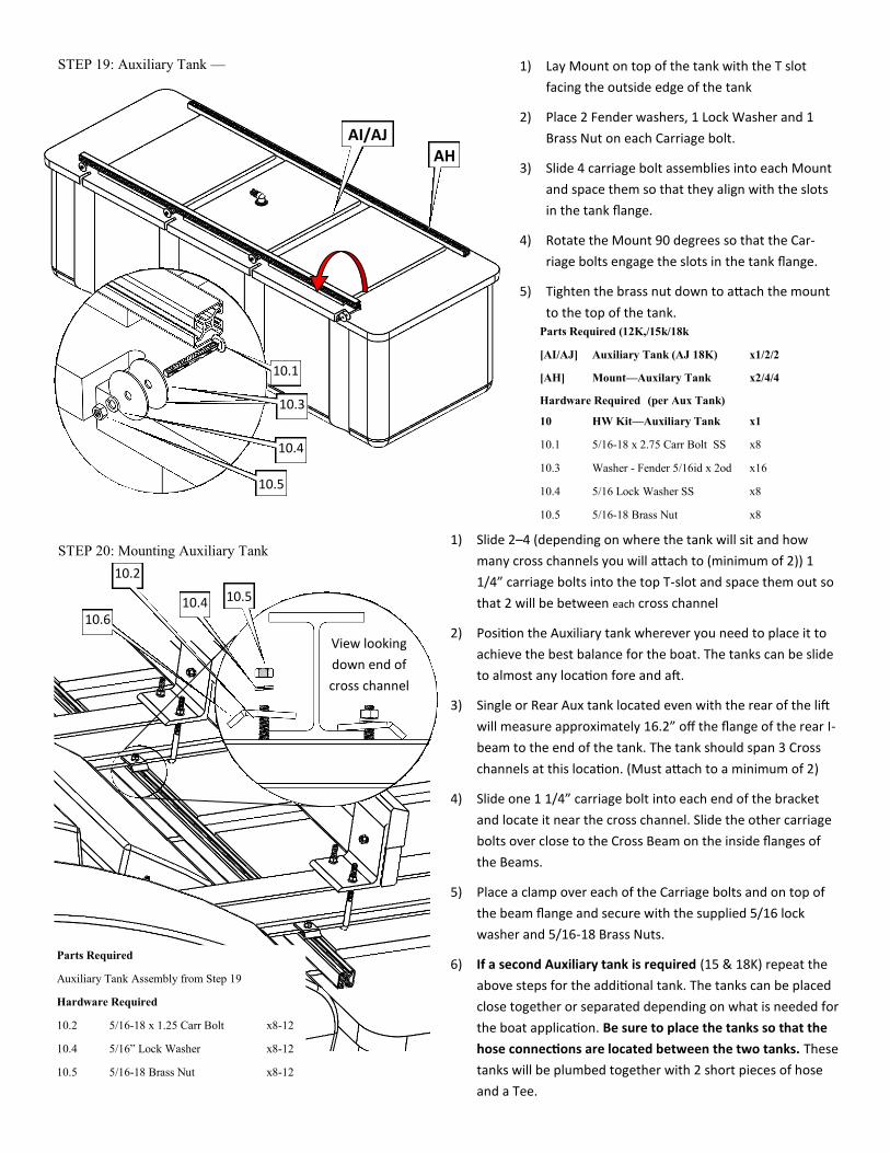
Parts Required (12K,/15k/18k
[AI/AJ] Auxiliary Tank (AJ 18K) x1/2/2
[AH] Mount—Auxilary Tank x2/4/4
Hardware Required (per Aux Tank)
10 HW Kit—Auxiliary Tank x1
10.1 5/16-18 x 2.75 Carr Bolt SS x8
10.3 Washer - Fender 5/16id x 2od x16
10.4 5/16 Lock Washer SS x8
10.5 5/16-18 Brass Nut x8
STEP 19: Auxiliary Tank —
STEP 20: Mounting Auxiliary Tank
Parts Required
Auxiliary Tank Assembly from Step 19
Hardware Required
10.2 5/16-18 x 1.25 Carr Bolt x8-12
10.4 5/16” Lock Washer x8-12
10.5 5/16-18 Brass Nut x8-12
1) Lay Mount on top of the tank with the T slot
facing the outside edge of the tank
2) Place 2 Fender washers, 1 Lock Washer and 1
Brass Nut on each Carriage bolt.
3) Slide 4 carriage bolt assemblies into each Mount
and space them so that they align with the slots
in the tank flange.
4) Rotate the Mount 90 degrees so that the Car-
riage bolts engage the slots in the tank flange.
5) Tighten the brass nut down to attach the mount
to the top of the tank.
AI/AJ AH
10.1
10.3
10.4
10.5
1) Slide 2–4 (depending on where the tank will sit and how
many cross channels you will attach to (minimum of 2)) 1
1/4” carriage bolts into the top T-slot and space them out so
that 2 will be between each cross channel
2) Position the Auxiliary tank wherever you need to place it to
achieve the best balance for the boat. The tanks can be slide
to almost any location fore and aft.
3) Single or Rear Aux tank located even with the rear of the lift
will measure approximately 16.2” off the flange of the rear I-
beam to the end of the tank. The tank should span 3 Cross
channels at this location. (Must attach to a minimum of 2)
4) Slide one 1 1/4” carriage bolt into each end of the bracket
and locate it near the cross channel. Slide the other carriage
bolts over close to the Cross Beam on the inside flanges of
the Beams.
5) Place a clamp over each of the Carriage bolts and on top of
the beam flange and secure with the supplied 5/16 lock
washer and 5/16-18 Brass Nuts.
6) If a second Auxiliary tank is required (15 & 18K) repeat the
above steps for the additional tank. The tanks can be placed
close together or separated depending on what is needed for
the boat application. Be sure to place the tanks so that the
hose connections are located between the two tanks. These
tanks will be plumbed together with 2 short pieces of hose
and a Tee.
10.2
10.6 10.4 10.5
View looking
down end of
cross channel
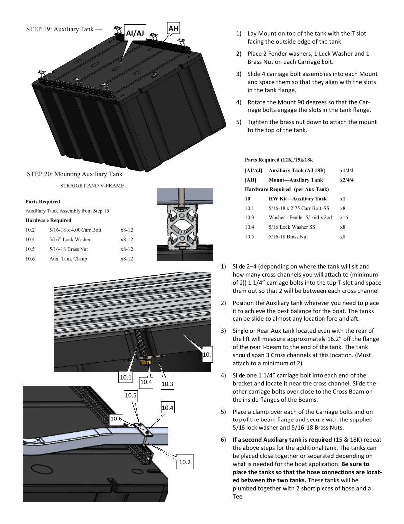
Parts Required (12K,/15k/18k
[AI/AJ] Auxiliary Tank (AJ 18K) x1/2/2
[AH] Mount—Auxilary Tank x2/4/4
Hardware Required (per Aux Tank)
10 HW Kit—Auxiliary Tank x1
10.1 5/16-18 x 2.75 Carr Bolt SS x8
10.3 Washer - Fender 5/16id x 2od x16
10.4 5/16 Lock Washer SS x8
10.5 5/16-18 Brass Nut x8
STEP 19: Auxiliary Tank —
STEP 20: Mounting Auxiliary Tank
STRAIGHT AND V-FRAME
Parts Required
Auxiliary Tank Assembly from Step 19
Hardware Required
10.2 5/16-18 x 4.00 Carr Bolt x8-12
10.4 5/16” Lock Washer x8-12
10.5 5/16-18 Brass Nut x8-12
10.6 Aux. Tank Clamp x8-12
1) Lay Mount on top of the tank with the T slot facing the outside edge of the tank
2) Place 2 Fender washers, 1 Lock Washer and 1 Brass Nut on each Carriage bolt.
3) Slide 4 carriage bolt assemblies into each Mount and space them so that they align with the slots in the tank flange.
4) Rotate the Mount 90 degrees so that the Car-riage bolts engage the slots in the tank flange.
5) Tighten the brass nut down to attach the mount to the top of the tank.
AH
10.5
1) Slide 2–4 (depending on where the tank will sit and how many cross channels you will attach to (minimum of 2)) 1 1/4” carriage bolts into the top T-slot and space them out so that 2 will be between each cross channel
2) Position the Auxiliary tank wherever you need to place it to achieve the best balance for the boat. The tanks can be slide to almost any location fore and aft.
3) Single or Rear Aux tank located even with the rear of the lift will measure approximately 16.2” off the flange of the rear I-beam to the end of the tank. The tank should span 3 Cross channels at this location. (Must attach to a minimum of 2)
4) Slide one 1 1/4” carriage bolt into each end of the bracket and locate it near the cross channel. Slide the other carriage bolts over close to the Cross Beam on the inside flanges of the Beams.
5) Place a clamp over each of the Carriage bolts and on top of the beam flange and secure with the supplied 5/16 lock washer and 5/16-18 Brass Nuts.
6) If a second Auxiliary tank is required (15 & 18K) repeat the above steps for the additional tank. The tanks can be placed close together or separated depending on what is needed for the boat application. Be sure to place the tanks so that the hose connections are locat-ed between the two tanks. These tanks will be plumbed together with 2 short pieces of hose and a Tee.
10.2
10.6
10.4
10.4 10.1
10.
10.3
AI/AJ
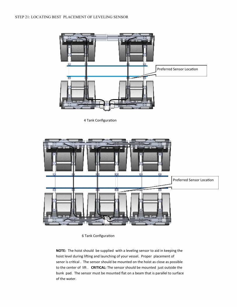
STEP 21: LOCATING BEST PLACEMENT OF LEVELING SENSOR
Preferred Sensor Location
4 Tank Configuration
6 Tank Configuration
Preferred Sensor Location
NOTE: The hoist should be supplied with a leveling sensor to aid in keeping the
hoist level during lifting and launching of your vessel. Proper placement of
senor is critical . The sensor should be mounted on the hoist as close as possible
to the center of lift . CRITICAL: The sensor should be mounted just outside the
bunk pad. The sensor must be mounted flat on a beam that is parallel to surface
of the water.

1) The sensor should be through bolted to the
mounting plate with the supplied hardware.
2) The sensor assembly should be oriented so
the sensor is mounted FACE UP on the cross
beam with the cable existing the sensor aft
of the lift.
3) Utilize the zip ties to fixture the sensor as-
sembly to the cross beam using the sup-
plied #6 self tapping screws.
4) Secure the sensor cable along the frame
back to the controller utilizing the zip ties.
Use #6 3/8” length
self tapping screws
FACE UP

Controller Setup and Operation
Thank You
We would like to a moment to thank you for purchasing a HarborHoistTM G1.5 lift.
We believe our lifts are the easiest to use on the market today and know that your
new lift will give you many years of trouble free service. The following pages will
provide you the necessary information for maintaining your new lift, as well as in-
structions on its use. Your new HarborHoistTM G1.5 lift is the result of extensive re-
search, design and development in environments where corrosion, marine growth,
and severe weather encourage lifting boats out of the water to help protect your
investment. As the leader in the industry, the HarborHoistTM G1.5 lift offers fea-
tures provided exclusively by HydroHoist ® Marine Group.
WARNING: Do not operate lift without the ini-
tial control setup. Damage to your lift or boat
can result from NOT programming controller
properly. Consult certified installer or facto-
ry for initial set-up
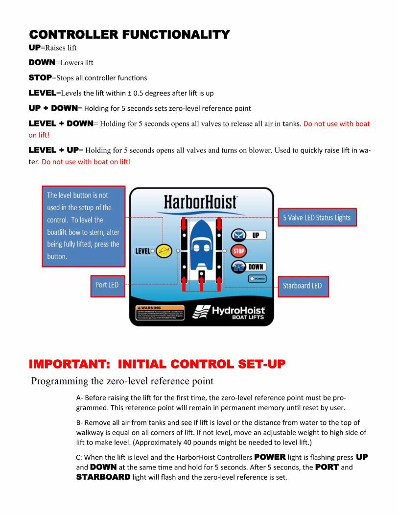
CONTROLLER FUNCTIONALITY UP=Raises lift
DOWN=Lowers lift
STOP=Stops all controller functions
LEVEL=Levels the lift within ± 0.5 degrees after lift is up
UP + DOWN= Holding for 5 seconds sets zero-level reference point
LEVEL + DOWN= Holding for 5 seconds opens all valves to release all air in tanks. Do not use with boat
on lift!
LEVEL + UP= Holding for 5 seconds opens all valves and turns on blower. Used to quickly raise lift in wa-
ter. Do not use with boat on lift!
IMPORTANT: INITIAL CONTROL SET-UP
Programming the zero-level reference point
A- Before raising the lift for the first time, the zero-level reference point must be pro-
grammed. This reference point will remain in permanent memory until reset by user.
B- Remove all air from tanks and see if lift is level or the distance from water to the top of
walkway is equal on all corners of lift. If not level, move an adjustable weight to high side of
lift to make level. (Approximately 40 pounds might be needed to level lift.)
C: When the lift is level and the HarborHoist Controllers POWER light is flashing press UP
and DOWN at the same time and hold for 5 seconds. After 5 seconds, the PORT and
STARBOARD light will flash and the zero-level reference is set.

General Operation
Familiarize yourself with the Control Box. We have created a simple to use 4 BUTTON user interface,
consisting of a UP, STOP, DOWN, and LEVEL buttons. These are the basic functions for the oper-
ating the HarborHoistTM G1.5 lift. Internal to the Control are state of the art valve controls and circuitry
that will insure that your lift comes up level each and every time you lift your boat from the water.
Lowering the Lift
• Make sure the Power LED is illuminated and flashing
• Press the DOWN button. This will open the valves.
• Allow the lift to submerge (Walkways will remain above water)
• Untie lift safety lines from boat
• Everyone may board the boat after the boat clears the lift
Raising the Lift
Float boat into established pick up position on lift
Tie off safety lines to the boat
Everyone must exit the boat before lifting.
Press UP button
Once the lift is fully raised, air bubbles will be visible exiting from all tanks.
Press STOP on Control
Leveling the Lift
In the raise function the controller will keep the lift within ±2 degrees for speed of operation. If the lift
needs to be leveled once all the way up, press the yellow LEVEL button and the lift will automatically
level the lift. The controller will release air our of the appropriate tank(s) to level the lift within ± 0.5 de-
grees.

Safety Tips
• Test GFCI on a monthly basis
To test:
• Plug in cord to power source
• Observe Light is on
• Push “test” bserve light is off
• Press “reset” and verify light is on
• Keep GFCI and plug out of water
• Keep Children away
• Do not overload the lift.
• Do not allow yourself to be distracted or walk away from the lift during operation.
• Make sure bilge pump is set for automatic.
NOTE: Significant water accumulation in the bilge may overload the lift.
• Make sure any ballast tanks are empty before lifting the boat.
• Lift is not designed for lifting people.
• No persons should be under the boat while it is in the suspended position.
• Weight must be distributed equally side to side and bow to stern before lifting, Otherwise the
boat will not center properly and appear to be crooked on the lift.
TEST
RESET
INDICATOR
LIGHT

Preventative Maintenance
• Because of the harsh environments in which the HarborHoistTM G1.5 can be
installed, it is very important to inspect your HarborHoistTM occasionally to
ensure it is at peak performance. On a monthly basis inspect the following:
• GFI trips and resets properly when the TEST and RESET buttons are pressed.
• All air hoses are firmly attached and there are no apparent leaks present.
• All the aluminum components are structurally sound and no heavy corrosion
is visible.
• The wood hull pads are structurally sound with no severe cracking.
• All mounting / attachment brackets are secure.
• If rope mooring is used, inspect the ropes for any issues that may compro-
mise the integrity.
• Most importantly, run your blower fan at least once a month even during the
off season. Press UP button on the control and let it run about a minute to
help keep the motor contacts and brushes clean.

Boat Fitment
Take care to clear shafts, thru hull fittings, chines, etc. Keel of boat must NOT rest on cross beam and should
clear the beam by at least 1 inch. Center of gravity of the the boat, must be in the the center of the lift (unless
Auxiliary tanks are used) bow to stern and port to starboard. This will evenly distribute the load over the lift
allowing for maximum lift height and maintains the appearance of the lift floating level.
For boats with Auxiliary Tanks— The goal here is to have the same lifting forces behind the CG of the boat as
you do in front in order to achieve good balance. The simple method for this is to make sure you have the same
amount of tank forward of the CG of the boat as you do behind the CG. For Auxiliary tank lifts that means we
can adjust the 8’ long center tanks to help accomplish this. Additional adjustment can be done by shifting the
boat fore and aft. The main tanks have a total tank length of 43’4” of tank for an 8 main tank unit. A 12K lift
has an additional 8’ of tank available, the 15K and 18K have 16’ additional each (18K are wider deeper tanks).
The CG of the boat when located with the transom at the end of the lift, should never be forward of the Center
of the lift. This condition suggests another set of Main tanks may be needed due to length (If it is over by less
than 18” the boat can be shifted back. If the Auxiliary tank (s) is completely behind the CG of the boat moving
the tank further back, amplifies the lifting effect of the rear. (Much like moving the smaller child further away
from the pivot on a teeter totter). If you need to move the Auxiliary tank back further than the end of the lift,
be sure you have enough space available between the outdrives and the tanks to avoid damage to one or the
other.
Important Notes:
It is the responsibility of the End User to insure that:
1) The lift is installed by a certified HydroHoist Installer.
2) The end user needs to understand how to operate the lift in a safe manner.
3) The end user should understand the need for regular inspection of the lift components.
4) Be sure the end user is informed and understands all safety and warning labels affixed to equipment.
No alterations or modifications may be made to the HydroHoist equipment without the express written consent
of HydroHoist Marine Group. Re-Installation, adjusting the bunks, and or adjusting the tank beam spacing of
the equipment must be performed to the standards set forth by HydroHoist Marine Group. It is the obligation
of the end user to inform any operators of the equipment of the above conditions. Owners Manuals and Safety
Warning Decals are available on request for HydroHoist Marine Group.
![Lofting Rev 3 Final 2009-07-30.pptx [Read-Only]adfisher/7962-09/Lofting-HO.pdf · 8/1/2009 1 July30, 2009 Brake & Wheel Assembly Team What is Lofting? A loft combines two or more](https://img.dokumen.tips/doc/110x75/5b854b5a7f8b9ae5498e16cf/lofting-rev-3-final-2009-07-30pptx-read-only-adfisher7962-09lofting-hopdf.jpg)