Embed Size (px)
Citation preview
arX
iv:c
ond-
mat
/061
1395
v2 [
cond
-mat
.sof
t] 2
5 M
ar 2
008
Structure of polydisperse inverse ferrofluids:
Theory and computer simulation
Y. C. Jian, Y. Gao and J. P. Huang∗
Surface Physics Laboratory and Department of Physics,
Fudan University, Shanghai 200433, China
R. Tao
Department of Physics, Temple University, Philadelphia, Pennsylvania 19122
(Dated: August 30, 2018)
Abstract
By using theoretical analysis and molecular dynamics simulations, we investigate the structure of col-
loidal crystals formed by nonmagnetic microparticles (ormagnetic holes) suspended in ferrofluids (called
inverse ferrofluids), by taking into account the effect of polydispersity in size of the nonmagnetic micropar-
ticles. Such polydispersity often exists in real situations. We obtain an analytical expression for the inter-
action energy of monodisperse, bidisperse, and polydisperse inverse ferrofluids. Body-centered tetragonal
(bct) lattices are shown to possess the lowest energy when compared with other sorts of lattices, and thus
serve as the ground state of the systems. Also, the effect of microparticle size distributions (namely, poly-
dispersity in size) plays an important role in the formationof various kinds of structural configurations.
Thus, it seems possible to fabricate colloidal crystals by choosing appropriate polydispersity in size.
∗ Corresponding author. Electronic address: [email protected]
1

I. INTRODUCTION
In recent years, inverse ferrofluids with nonmagnetic colloidal microparticles suspended in a
host ferrofluid (also called magnetic fluid)1−3 have drawn considerable attention for its potential
application in its industrial applications and potential use in biomedicine.4−11 The size of the non-
magnetic microparticles are about1 ∼ 100µm, which can be easily made in experiments, such as
polystyrene microparticles. The inverse ferrofluid systemcan be modelled in a dipolar interaction
approximation. Here, the dipolar interaction approximation is actually the first-order approxima-
tion of multipolar interaction. Because the nonmagnetic microparticles are much larger than the
ferromagnetic nanoparticles in a host ferrofluid, the host can theoretically be treated as a uniform
continuum background in which the much larger nonmagnetic microparticles are embedded. If
an external magnetic field is applied to the inverse ferrofluid, the nonmagnetic microparticles sus-
pended in the host ferrofluid can be seen to posses an effective magnetic moment but opposite in
direction to the magnetization of the host ferrofluid. As theexternal magnetic field increases, the
nonmagnetic microparticles aggregate and form chains parallel with the applied magnetic field.
These chains finally aggregate to a column-like structure, completing a phase transition process,
which is similar to the cases of electrorheological fluids and magnetorheological fluids under exter-
nal electric or magnetic fields. The columns can behave as different structures like body-centered
tetragonal (bct) lattices, face centered cubic (fcc) lattices, hexagonal close packed (hcp) lattices,
and so on. In this work, we assume that the external magnetic field is large enough to form differ-
ent lattice structures. The actual value of the external magnetic field needed to form such structures
is related to the volume fraction of the nonmagnetic microparticles and the magnetic properties of
the host ferrofluid.
In this work, we shall use the dipole-multipole interactionmodel12 to investigate the structure
of inverse ferrofluids. In ref 12, Zhang and Widom discussed how the geometry of elongated
microparticles will affect the interaction between two droplets, and introduced higher multipole
moments’ contribution by using a dipole and multipole (dipole-multipole) interaction model to
give a more exact expression of interaction energy than using the dipole and dipole (dipole-dipole)
interaction model. The leading dipole-dipole force does not reflect the geometry relation between
the microparticles nearby, while the dipole-multipole model includes the contributions from the
size mismatch and is simpler and practical than the multipolar expansion theory13,14 in dealing with
the complex interaction between microparticles for its accuracy. Size distributions can be regarded
2

as a crucial factor which causes depletion forces in colloidal droplets.15 Even though researchers
have tried their efforts to fabricate monodisperse systemsfor obtaining optimal physical or chemi-
cal properties,16,17 polydispersity in size of microparticles often exists in real situations,18−22 since
the microparticles always possess a Gaussian or log-normaldistribution. Here we consider size
distributions as an extra factor affecting the interactionenergy. Polydisperse ferrofluid models are
usually treated in a global perspective using chemical potential or free energy methods,6,23,24 while
the current model concerns the local nature in the crystal background. A brief modelling is carried
out for the size distribution picture in the formation of crystal lattices. The purpose of this paper
is to use this model to treat the structure formation in monodisperse, bidisperse, and polydisperse
inverse ferrofluids, thus yielding theoretical predictions for the ground state for the systems with
or without microparticle size distributions (or polydispersity in size). It is found that when the
size mismatch is considered between the microparticles, the interaction between them becomes
complex and sensitive to the different configurations. Thismethod can also be extended to other
ordered configurations in polydisperse crystal systems.
This paper is organized as follows. In Section II, based on the dipole-multipole interaction
model, we present the basic two-microparticle interactionmodel to derive interaction potentials.
In Sections III and IV, we apply the model to three typical structures of colloid crystals formed in
inverse ferrofluids, and then investigate the ground state in two different configurations by taking
into account the effect of size distributions. As an illustration, in Section V we perform molecular
dynamics simulations to give a picture of the microparticlesize distribution in the formation of a
bct lattice in bidisperse inverse ferrofluids. The paper ends with a discussion and conclusion in
Section VI.
II. INTERACTION MODEL FOR TWO NONMAGNETIC MICROPARTICLES
We start by considering a simple situation in which two nonmagnetic spherical microparticles
(or calledmagnetic holes) are put nearby inside a ferrofluid which is homogeneous at the scale of
a sphere in an applied uniform magnetic fieldH, see Figure 1. The nonmagnetic microparticles
create holes in the ferrofluid, and corresponding to the amount and susceptibility of the ferrofluid,
they possess the effective magnetic moment, which can be described by25 m = − χf
1+ 2
3χfV H =
−χV H, whereχf (or χ) means the magnetic susceptibility of the host (or inverse)ferrofluid.
When the two nonmagnetic microparticles placed together with distancerij away, we can view
3
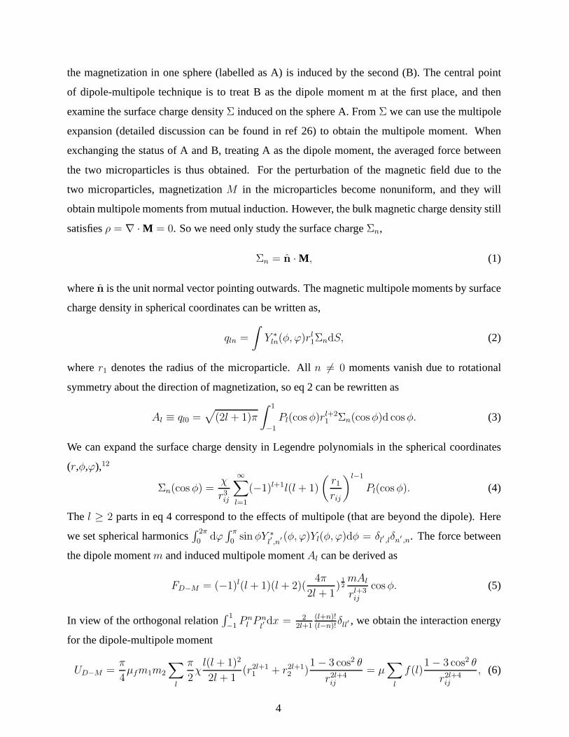
the magnetization in one sphere (labelled as A) is induced bythe second (B). The central point
of dipole-multipole technique is to treat B as the dipole moment m at the first place, and then
examine the surface charge densityΣ induced on the sphere A. FromΣ we can use the multipole
expansion (detailed discussion can be found in ref 26) to obtain the multipole moment. When
exchanging the status of A and B, treating A as the dipole moment, the averaged force between
the two microparticles is thus obtained. For the perturbation of the magnetic field due to the
two microparticles, magnetizationM in the microparticles become nonuniform, and they will
obtain multipole moments from mutual induction. However, the bulk magnetic charge density still
satisfiesρ = ∇ · M = 0. So we need only study the surface chargeΣn,
Σn = n · M , (1)
wheren is the unit normal vector pointing outwards. The magnetic multipole moments by surface
charge density in spherical coordinates can be written as,
qln =
∫
Y ∗ln(φ, ϕ)r
l1ΣndS, (2)
wherer1 denotes the radius of the microparticle. Alln 6= 0 moments vanish due to rotational
symmetry about the direction of magnetization, so eq 2 can berewritten as
Al ≡ ql0 =√
(2l + 1)π
∫ 1
−1
Pl(cosφ)rl+21 Σn(cosφ)d cosφ. (3)
We can expand the surface charge density in Legendre polynomials in the spherical coordinates
(r,φ,ϕ),12
Σn(cos φ) =χ
r3ij
∞∑
l=1
(−1)l+1l(l + 1)
(
r1
rij
)l−1
Pl(cos φ). (4)
The l ≥ 2 parts in eq 4 correspond to the effects of multipole (that arebeyond the dipole). Here
we set spherical harmonics∫ 2π
0dϕ
∫ π
0sinφY ∗
l′,n
′ (φ, ϕ)Yl(φ, ϕ)dφ = δl′ ,lδn′ ,n. The force between
the dipole momentm and induced multipole momentAl can be derived as
FD−M = (−1)l(l + 1)(l + 2)(4π
2l + 1)1
2
mAl
rl+3ij
cosφ. (5)
In view of the orthogonal relation∫ 1
−1P nl P
nl′dx = 2
2l+1(l+n)!(l−n)!
δll′ , we obtain the interaction energy
for the dipole-multipole moment
UD−M =π
4µfm1m2
∑
l
π
2χl(l + 1)2
2l + 1(r2l+1
1 + r2l+12 )
1− 3 cos2 θ
r2l+4ij
= µ∑
l
f(l)1− 3 cos2 θ
r2l+4ij
, (6)
4
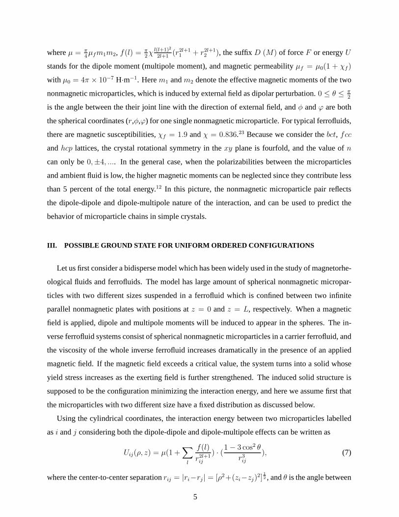
whereµ = π4µfm1m2, f(l) = π
2χ
l(l+1)2
2l+1(r2l+1
1 + r2l+12 ), the suffixD (M) of forceF or energyU
stands for the dipole moment (multipole moment), and magnetic permeabilityµf = µ0(1 + χf)
with µ0 = 4π × 10−7 H·m−1. Herem1 andm2 denote the effective magnetic moments of the two
nonmagnetic microparticles, which is induced by external field as dipolar perturbation.0 ≤ θ ≤ π2
is the angle between the their joint line with the direction of external field, andφ andϕ are both
the spherical coordinates (r,φ,ϕ) for one single nonmagnetic microparticle. For typical ferrofluids,
there are magnetic susceptibilities,χf = 1.9 andχ = 0.836.23 Because we consider thebct, fcc
andhcp lattices, the crystal rotational symmetry in thexy plane is fourfold, and the value ofn
can only be0,±4, .... In the general case, when the polarizabilities between themicroparticles
and ambient fluid is low, the higher magnetic moments can be neglected since they contribute less
than 5 percent of the total energy.12 In this picture, the nonmagnetic microparticle pair reflects
the dipole-dipole and dipole-multipole nature of the interaction, and can be used to predict the
behavior of microparticle chains in simple crystals.
III. POSSIBLE GROUND STATE FOR UNIFORM ORDERED CONFIGURATI ONS
Let us first consider a bidisperse model which has been widelyused in the study of magnetorhe-
ological fluids and ferrofluids. The model has large amount ofspherical nonmagnetic micropar-
ticles with two different sizes suspended in a ferrofluid which is confined between two infinite
parallel nonmagnetic plates with positions atz = 0 andz = L, respectively. When a magnetic
field is applied, dipole and multipole moments will be induced to appear in the spheres. The in-
verse ferrofluid systems consist of spherical nonmagnetic microparticles in a carrier ferrofluid, and
the viscosity of the whole inverse ferrofluid increases dramatically in the presence of an applied
magnetic field. If the magnetic field exceeds a critical value, the system turns into a solid whose
yield stress increases as the exerting field is further strengthened. The induced solid structure is
supposed to be the configuration minimizing the interactionenergy, and here we assume first that
the microparticles with two different size have a fixed distribution as discussed below.
Using the cylindrical coordinates, the interaction energybetween two microparticles labelled
asi andj considering both the dipole-dipole and dipole-multipole effects can be written as
Uij(ρ, z) = µ(1 +∑
l
f(l)
r2l+1ij
) · (1− 3 cos2 θ
r3ij), (7)
where the center-to-center separationrij = |ri−rj | = [ρ2+(zi−zj)2]
1
2 , andθ is the angle between
5
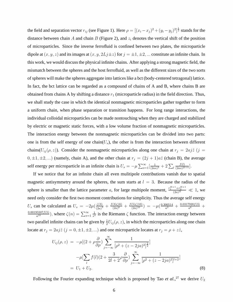
the field and separation vectorrij (see Figure 1). Hereρ = [(xi−xj)2+(yi−yj)
2]1
2 stands for the
distance between chainA and chainB (Figure 2), andzi denotes the vertical shift of the position
of microparticles. Since the inverse ferrofluid is confined between two plates, the microparticle
dipole at(x, y, z) and its images at(x, y, 2Lj±z) for j = ±1,±2, ... constitute an infinite chain. In
this work, we would discuss the physical infinite chains. After applying a strong magnetic field, the
mismatch between the spheres and the host ferrofluid, as wellas the different sizes of the two sorts
of spheres will make the spheres aggregate into lattices like a bct (body-centered tetragonal) lattice.
In fact, the bct lattice can be regarded as a compound of chains of A and B, where chains B are
obtained from chains A by shifting a distancer1 (microparticle radius) in the field direction. Thus,
we shall study the case in which the identical nonmagnetic microparticles gather together to form
a uniform chain, when phase separation or transition happens. For long range interactions, the
individual colloidal microparticles can be made nontouching when they are charged and stabilized
by electric or magnetic static forces, with a low volume fraction of nonmagnetic microparticles.
The interaction energy between the nonmagnetic microparticles can be divided into two parts:
one is from the self energy of one chain(Us), the other is from the interaction between different
chains(Uij(ρ, z)). Consider the nonmagnetic microparticles along one chainat rj = 2ajz (j =
0,±1,±2, ...) (namely, chain A), and the other chain atrj = (2j + 1)az (chain B), the average
self energy per microparticle in an infinite chain isUs = −µ∑∞
s=1[1
(2as)3+ 2
∑
lf(l)
(2as)2l+4 ].
If we notice that for an infinite chain all even mulitipole contributions vanish due to spatial
magnetic antisymmetry around the spheres, the sum starts atl = 3. Because the radius of the
sphere is smaller than the lattice parametera, for large multipole moment,r2l+1
1+r2l+1
2
(2a)2l≪ 1, we
need only consider the first two moment contributions for simplicity. Thus the average self energy
Us can be calculated asUs = −2µ( ζ(3)
(2a)3+ f(3)ζ(6)
(2a)6+ f(5)ζ(10)
(2a)10) = −µ(0.300514
a3+ 0.0317920f(3)
a6+
0.00195507f(5)a10
), whereζ(n) =∑∞
s=11sn
is the Riemannζ function. The interaction energy between
two parallel infinite chains can be given by12Uij(ρ, z), in which the microparticles along one chain
locate atrj = 2ajz (j = 0,±1,±2, ...) and one microparticle locates atrj = ρ+ zz,
Uij(ρ, z) = −µ[(2 + ρ∂
∂ρ)
∞∑
j=−∞
1
[ρ2 + (z − 2ja)2]3
2
]
−µ[∑
l
f(l)(2 +3
2l + 2ρ∂
∂ρ)
∞∑
j=−∞
1
[ρ2 + (z − 2ja)2]l+2]
= U1 + U2. (8)
Following the Fourier expanding technique which is proposed by Taoet al.,27 we deriveU2
6
which is the second part ofUij(ρ, z) as
U2 = −µ∑
l
f(l)
4aρ2l+3[−(2l + 1)
√πΓ(l + 3
2)
Γ(l + 3)+ 2
1
2−l(
sρ
a)l+
3
2πl+2 cos(sπz
a) · S] (9)
with
S =∞∑
s=1
(K 5
2
( sπρ)
Γ(l + 3)+
4K 3
2
( sπρ)
Γ(l + 2)). (10)
HereKi(x) represents theith order modified Bessel function,Γ(x) theΓ function, ands denotes
the index in Fourier transformation.26 And the dipole-dipole energyU1 is written as
U1 = − µ
a3
∞∑
s=1
2π2s2K0(sπρ
a) cos(
sπz
a). (11)
We obtain the expression forUij(ρ, z), and the interaction energy per nonmagnetic microparti-
cle U(ρ, z) is Us +12
∑
k Uij(ρ, z), where∑
k denotes the summation over all chains except the
considered microparticle. For the same reason of approximation discussed above, we need only
choose the first two terms(l = 3 andl = 5) in the calculation.
The interaction between chain A and chain B depends on the shift z, the lattice structure
and the nonmagnetic microparticle size. An estimation of the interaction energy per nonmag-
netic microparticle includes the nearest and next-nearestneighboring chains, here we could
discuss three most common lattice structures:bct, fcc, and hcp lattices. For the above lat-
tices, their corresponding energy ofUij(ρ, z) can be respectively approximated asUij,bct(ρ, z) =
4Uij(√3a, z = 0)− 4Uij(
√6a, z = 0), Uij,fcc(ρ, z) = 4Uij(
√3a, z = 0)− 2Uij(2a, z = 0), and
Uij,hcp(ρ, z) = 3Uij(√3a, z = 0)− 4Uij(2a, z = 0).
Figure 3 shows, for different lattices, the dependence ofUij(ρ, z) on the vertical position shift
z, which determines whether the interaction is attractive orrepulsive.Uij(ρ, z) reflects the energy
difference between chain A and chain B for (a)bct, (b) fcc, and (c)hcp lattices. It is evident
that, for the same lattice structure,Uij(ρ, z) is minimized when the size difference between chain
A and chain B is the smallest. For the sake of comparison, we also plot the results obtained by
considering the dipole-dipole interaction only. Comparing the different lattices, we find that the
bct lattice possesses the smallest energy at the equilibrium point, thus being the most stable.
Figure 4 displays the interaction energyU(ρ, z) as a function of the lattice constanta for the
bct lattice. It is shown that as the lattice constant increases,the dipole-multipole effect becomes
weaker and weaker, and eventually it reduces to the dipole-dipole effect. In other words, as the
lattice constant is smaller, one should take into account the dipole-multipole effect. In this case,
the effect of polydispersity in size can also play an important role.
7
Figure 5 displays the interaction energy per nonmagnetic microparticleU(ρ, z) vs the lattice
parametera for different lattice structures. Thebct structure also proves to be the most stable state
while thehcp lattice has the highest energy. It also shows that the energygap betweenbct lattice
andfcc lattice exists but is small. Figure 6(a) shows that the energy gap∆U = Ubct−Ufcc is about
0.5 percent of the interaction energy value. In this aspect,thebct lattice proves always to be a more
stable structure comparing withfcc. As the radius of microparticles increases, the energy gap
betweenbct andfcc lattice enlarges accordingly. That is, thebct lattice becomes much more stable.
Figure 6(b) shows thebct lattice energyU(ρ, z) in respect of different sizes of microparticles
for chain A and chain B. It can be seen that the close touching packing (r1 = r2 = a) has
the lowest energy state. However, also from the graph, the crystal with the same microparticle
size (monodisperse system) may not be the lowest energy state, which gives a possible way of
fabricating different crystals by tuning the distributionof microparticle size.
IV. POLYDISPERSE SYSTEM WITH RANDOM DISTRIBUTIONS
In Section III, we have discussed the structure and interaction in a bidisperse inverse ferrofluid
(namely, containing microparticles with two different sizes). But the interaction form in poly-
disperse crystal system is complex and sensitive to the microstructure in the process of crystal
formation. Now we investigate the structure of polydisperse inverse ferrofluids with microparti-
cles of different sizes in a random configuration. To proceed, we assume that the average radiusr
satisfies the Gaussian distribution
P (r) =1√2πσ
exp
(
−(r − r0)2
2σ2
)
, (12)
whereσ denotes the standard deviation of the distribution of microparticle radius, which describes
the degree of polydispersity. Integrating eq 9 byr1 and r2, we could get the average dipole-
multipole energyU 2. Doing the same calculation to self energyUs, we can get the average inter-
action energyU(ρ, z) = Us +U1 +U 2, where the microparticle sizer1 andr2 are replaced by the
mean radiusr0. The microparticle sizes will be distributed in a wider range as long as a largerσ
is chosen.
Figure 7(a) shows the ground state interaction energy ofbct lattice for different polydisperse
distributions. As the degree of polydispersityσ increases, the energyU(ρ, z) drops fast, especially
when the distribution of microparticle size gathers aroundr = a. It shows that the inverse fer-
8
rofluid crystal in the formation of ground state tends to include microparticles possessing more
different sizes. The crystal configuration energy of two uniform chains with identical micropar-
ticle aggregation is also plotted in the graph. Here we consider two cases. First, we assume the
microparticles in chain A and chain B are identical,r1 = r2 = r0. As r0 increases, the behavior of
energy decreasing is discovered to be similar with the random configuration withσ = 0.2r0. Sec-
ond, we set for one chain, such as chain B, the microparticle size r2 = a to be unchanged, while
the microparticle sizer1 of chain A increases. It shows that thebct lattice energy for the second
case is lower than the first case and two other random configurations. And it also shows that the
random configuration is not always the state with the lowest energy. It proves that polydisperse
systems are sensitive to many factors which can determine the microstructure. Figure 7(b) shows
the energy gap between bct and fcc lattices for different distribution deviationσ. It is evident that
higherσ leads to larger energy difference between bct and fcc, especially at largerr0. In other
words, at largerr0 and/orσ, bct lattices are much more stable thanfcc.
V. MOLECULAR-DYNAMIC SIMULATIONS
Here we use a molecular-dynamic simulation, which was proposed by Taoet al.,28 in order
to briefly discuss the structure formation of bidisperse inverse ferrofluids. The simulation herein
involves dipolar forces, multipole forces, viscous drag forces and the Brownian force. The mi-
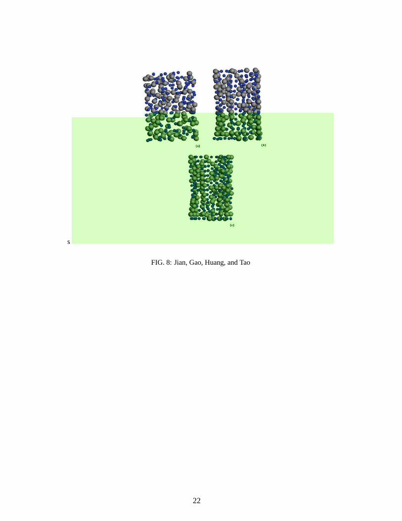
croparticles are confined in a cell between two parallel magnetic pole plates, and they are ran-
domly distributed initially, as shown in Figure 8(a). The motion of a microparticlei is described
by a Langevin equation,
mad2~ri
dt2= ~Fi − 3πση
d~ri
dt+ ~Ri(t), (13)
where the second term in the right-hand side is the Stokes’s drag force,Ri is the Brownian force,
and
Fi =∑
i 6=j
(fij + frepij ) + fwall
i . (14)
Herefij = −∇U(ρ, z), whilefrepij , fwall
i andRi(t), have the similar expressions as those in ref 27
and the references therein. In eq 13,ma andσ are respectively the average mass and diameter of
microparticles. Figure 8 shows the inverse ferrofluid structure with the parameters, magnetic field
H = 14Oe, temperatureT = 300K, A′ ≡ µfm1m2
3π2σ6η2ma = 10−2, andB′ ≡
√6πkBTσ9η/τ
3µfm1m2= 10−4.
HereA′
denotes the ratio of a dipolar force to a viscous force,B′
the ratio of Brownian force to a
9

dipolar force,kB the Boltzmann constant, andτ the subinterval time step.
We take into account a bidisperses system that contains two kinds of microparticles with dif-
ferent sizes, as shown in Figure 8. In details, this figure displays the configuration of microparticle
distribution in a bidisperse system at (a) the initial state, (b) the state after 15 000 time steps, and
(c) the state after 80 000 time steps. The order of Figure 8(c)is better than Figure 8(b). Here we
should remark that 80 000 steps give the sufficient long time steps to reach the equilibrium state
for the case of our interest. The structure for the bi-disperse system in Figure 8(b) and (c) has
the following features: (i) In the field direction, the largespheres form the main chains from one
plate to the other, where the large spheres touch each other.(ii) The large spheres also form many
smallbct lattice grains. However, they do not form a largebct lattice. (iii) The small spheres fill
the gaps between thesebct lattice grains. From Figure 8, it is observed that, for the parameters
currently used, the order of a bidisperse system (which is abct-like structure) is not as good as that
of monodisperse system (no configurations shown herein). Weshould remark that the long-range
interaction can yield the above-mentioned bct lattice structure, but some perturbations caused by
the Brownian movement existing in the system can change it toanother lattice structure which
has similar free energy. Therefore, for the bi-disperse system of our interest, the large spheres
form the main chains from one plate to the other in the field direction, thus forming many small
bct-like lattice structures. While small spheres fill the gaps between these bct-like lattices, they
themselves do not form a bct-like lattice due to such perturbations. Here we should also mention
that the degree of order of a specific system depends on the choice of various physical parameters,
for example, the size of microparticles and so forth.
VI. SUMMARY
In summary, by using theoretical analysis and molecular dynamics simulations, we investi-
gate the structure of colloidal crystals formed by nonmagnetic microparticles (or magnetic holes)
suspended in a host ferrofluid, by taking into account the effect of polydispersity in size of the non-
magnetic microparticles. We obtain an analytical expression for the interaction energy of monodis-
perse, bidisperse, and polydisperse inverse ferrofluids. The bct lattices are shown to possess the
lowest energy when compared with other sorts of lattices, and thus serve as the ground state of the
systems. Also, the effect of microparticle size distributions (namely, polydispersity in size) plays
an important role in the formation of various kinds of structural configurations. Thus, it seems
10
possible to fabricate colloidal crystals by choosing appropriate polydispersity in size. As a matter
of fact, it is straightforward to extend the present model tomore ordered periodic systems,29 in
which the commensurate spacings can be chosen as equal or different.
Acknowledgments
Two of us (Y.C.J. and J.P.H.) are grateful to Dr. Hua Sun for valuable discussion. This work was
supported by the National Natural Science Foundation of China under Grant No. 10604014, by
the Shanghai Education Committee and the Shanghai Education Development Foundation (”Shu
Guang” project), by the Pujiang Talent Project (No. 06PJ14006) of the Shanghai Science and
Technology Committee, and by Chinese National Key Basic Research Special Fund under Grant
No. 2006CB921706. Y.C.J. acknowledges the financial support by Tang Research Funds of Fudan
University, and by the ”Chun Tsung” Scholar Program of FudanUniversity.
11
References and Notes
(1) Odenbach S.,Magnetoviscous Effects in FerrofluidsSpringer, Berlin, 2002.
(2) Meriguet G.; Cousin F.; Dubois E.; Boue F.; Cebers A.; Farago B.; and Perzynski W.J.
Phys. Chem. B2006, 110, 4378.
(3) Sahoo Y.; Goodarzi A.; Swihart M. T.; Ohulchanskyy T. Y.;Kaur N.; Furlani E. P.; and
Prasad P. N.J. Phys. Chem. B2005, 109, 3879.
(4) Toussaint R.; Akselvoll J.; Helgesen G.; Skjeltorp A. T.; and Flekkøy E. G.Phys. Rev. E.
2004, 69, 011407.
(5) Skjeltorp A. T.Phys. Rev. Lett.1983, 51, 2306.
(6) Zubarev A. Y. and Iskakova L. Y.Physica A2003, 335, 314.
(7) Chantrell R. and Wohlfart E.J. Magn. Magn. Mater.1983, 40, 1.
(8) Rosensweig R. E.Annu. Rev. Fluid Mech.1987, 19, 437.
(9) Ugelstad J. et al,Blood Purif.1993, 11, 349.
(10) Hayter J. B.; Pynn R.; Charles S.; Skjeltorp A. T.; Trewhella J.; Stubbs G.; and Timmins
P.Phys. Rev. Lett.1989, 62, 1667.
(11) Koenig A.; Hebraud P.; Gosse C.; Dreyfus R.; Baudry J.;Bertrand E.; and Bibette J.Phys.
Rev. Lett.2005, 95, 128301.
(12) Zhang H. and Widom M.Phys. Rev. E.1995, 51, 2099.
(13) Friedberg R. and Yu Y. K.Phys. Rev. B.1992, 46, 6582.
(14) Clercx H. J. H. and Bossis G.Phys. Rev. B.1993, 48,2721.
(15) Mondain-Monval O.; Leal-Calderon F.; Philip J.; and Bibette J.Phys. Rev. Lett.1995, 75,
3364.
(16) Sacanna S. and Philipse A. P.Langmuir2006, 22, 10209.
(17) Claesson E. M. and Philipse A. P.Langmuir2005, 21, 9412.
(18) Dai Q. Q.; Li D. M.; Chen H. Y.; Kan S. H.; Li H. D.; Gao S. Y.;Hou Y. Y.; Liu B. B. and
Zou G. T.J. Phys. Chem. B2006,110, 16508.
(19) Ethayaraja M.; Dutta K.; and Bandyopadhyaya R.J. Phys. Chem. B2006, 110, 16471.
(20) Jodin L.; Dupuis A. C.; Rouviere E.; and Reiss P.J. Phys. Chem. B2006, 110, 7328.
(21) Gao L. and Li Z. Y.J. Appl. Phys.2002, 91, 2045.
(22) Wei E. B.; Poon Y. M.; Shin F. G.; and Gu G. Q.Phys. Rev. B2006, 74, 014107.
(23) Kristof T. and Szalai I.Phys. Rev. E2003, 68, 041109.
12
(24) Huang J. P. and Holm C.Phys. Rev. E2004, 70, 061404.
(25) J.Cernak, G. Helgesen, and A. T. Skjeltorp,Phys. Rev. E2004, 70, 031504.
(26) Jackson J. D.,Classical Electrodynamics, 3rd edition Wiley, New York, 1999, Chapter 4.
(27) Tao R. and Sun J. M.Phys. Rev. Lett.1991, 67, 398.
(28) Tao R. and Jiang Q.Phys. Rev. Lett.1994, 73, 205.
(29) Gross M. and Wei C.Phys. Rev. E2000, 61, 2099.
13

Figure captions
Figure 1. Schematic graph showing two nonmagnetic microparticles (magnetic hole) of radius
r1 andr2, suspended in a ferrofluid under an applied magnetic fieldH.
Figure 2. Three different lattices,bct, fcc, andhcp, which are composed of non-touching
microparticles with different size distribution.
Figure 3. The dependence of interaction energyUI(ρ, z) (in units ofµ0) versus vertical shiftz
for different lattices: (a)bct, (b) fcc, and (c)hcp. In the legend, ”dipole-dipole” denotes the case
that the dipole-dipole interaction is only considered for calculating the interaction energy.
Figure 4. The interaction energyU(ρ, z) versus lattice constanta. The solid line stands for the
case in which the dipole-dipole interaction is only considered.
Figure 5. The interaction energy per microparticleU(ρ, z) versus lattice constanta for different
lattices,bct, fcc, andhcp.
Figure 6. (a) The energy gap∆U = Ubct − Ufcc (in units of µ0) versus different size of
nonmagnetic microparticles in chain A and chain B; (b) Thebct lattice energyU(ρ, z) (in units of
µ0) versus different sizes of nonmagnetic microparticles in chain A and chain B.
Figure 7. (a) The ground state interaction energy of abct lattice versus microparticle sizer0
for random polydispersity configuration (solid, dashed, and dotted lines) and a configuration com-
posed of two different uniform chains (dash-dotted and short-dash-dotted lines). (b) The energy
gap∆U betweenbct andfcc lattices for random polydispersity versusr0.
Figure 8. The configuration of nonmagnetic microparticle distribution at (a) the initial state,
(b) the state after 15000 time steps, and (c) the state after 80000 time steps.
14
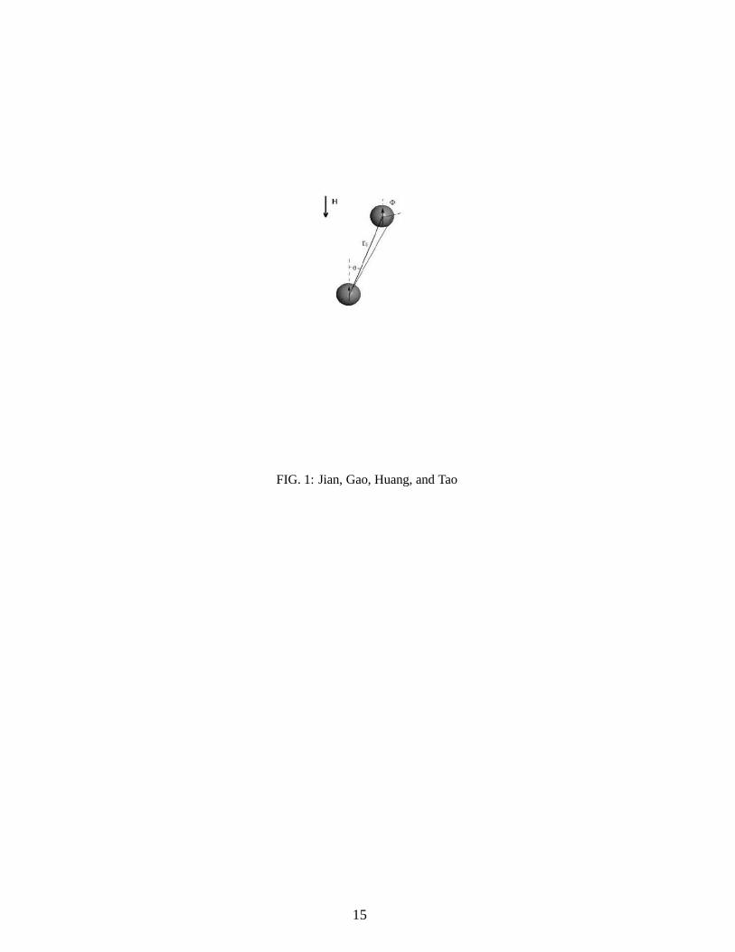
FIG. 1: Jian, Gao, Huang, and Tao
15
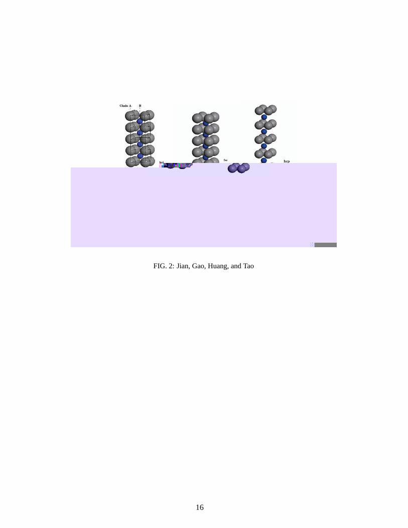
FIG. 2: Jian, Gao, Huang, and Tao
16

FIG. 3: Jian, Gao, Huang, and Tao
17

FIG. 4: Jian, Gao, Huang, and Tao
18

FIG. 5: Jian, Gao, Huang, and Tao
19
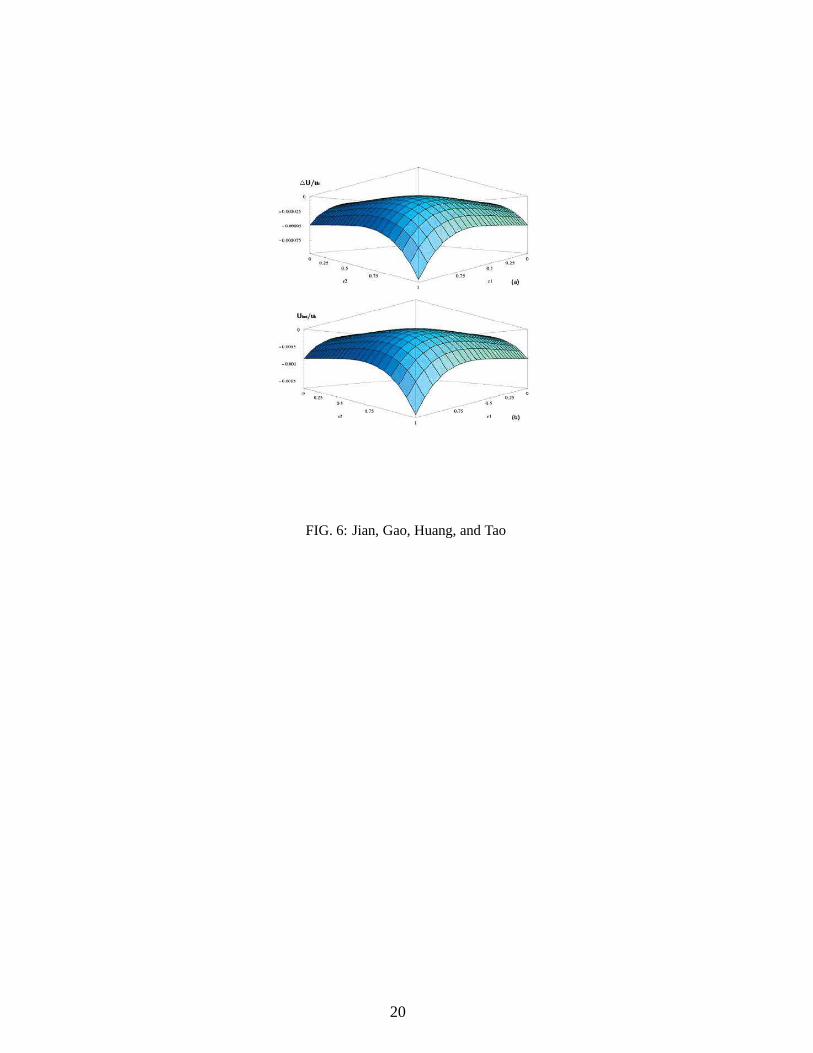
FIG. 6: Jian, Gao, Huang, and Tao
20
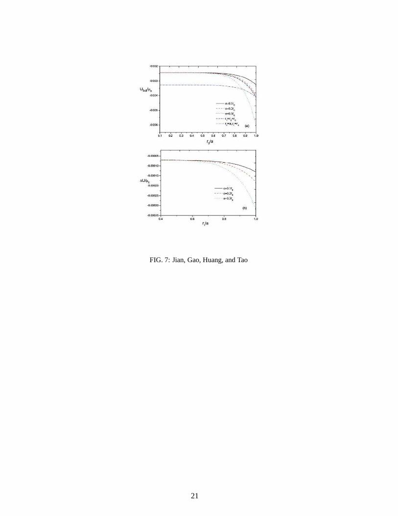
FIG. 7: Jian, Gao, Huang, and Tao
21
s
FIG. 8: Jian, Gao, Huang, and Tao
22