Embed Size (px)
Citation preview
Technical Data
XM Monitoring Modules SpecificationsCatalog Numbers 1440 Series
The XM® series of intelligent I/O modules process, in real-time, the critical parameters that are used to assess the current health and predict the future health of industrial machinery. This real-time processing provides machinery protection and reduces downtime. Use the XM modules in a standalone system, or integrate them with existing automation and control systems.
Type Module Cat. No. Page
Measurement modules XM DYN Dynamic Measurement Module 1440-DYN02-01RJ 2
XM-124 Standard Dynamic Measurement Module 1440-SDM02-01RA 6
XM-220 Dual Speed Module 1440-SPD02-01RB 12
Relay modules XM-441 Expansion Relay Module 1440-REX00-04RD 17
XM-442 Voted EODS Relay Module 1440-REX03-04RG 20
Accessories Terminal Bases 1440-TB-A, 1440-TB-B, 1440-TB-D, 1440-TB-G, 1440-TBS-J
23
Serial Configuration Utility N/A 24
Fuse Kit 1440-5AFUSEKIT 24
Serial Communication Cable 1440-SCDB9FXM2 25
ControlNet Adapter 1440-ACNR 25
XM Monitoring Modules Specifications
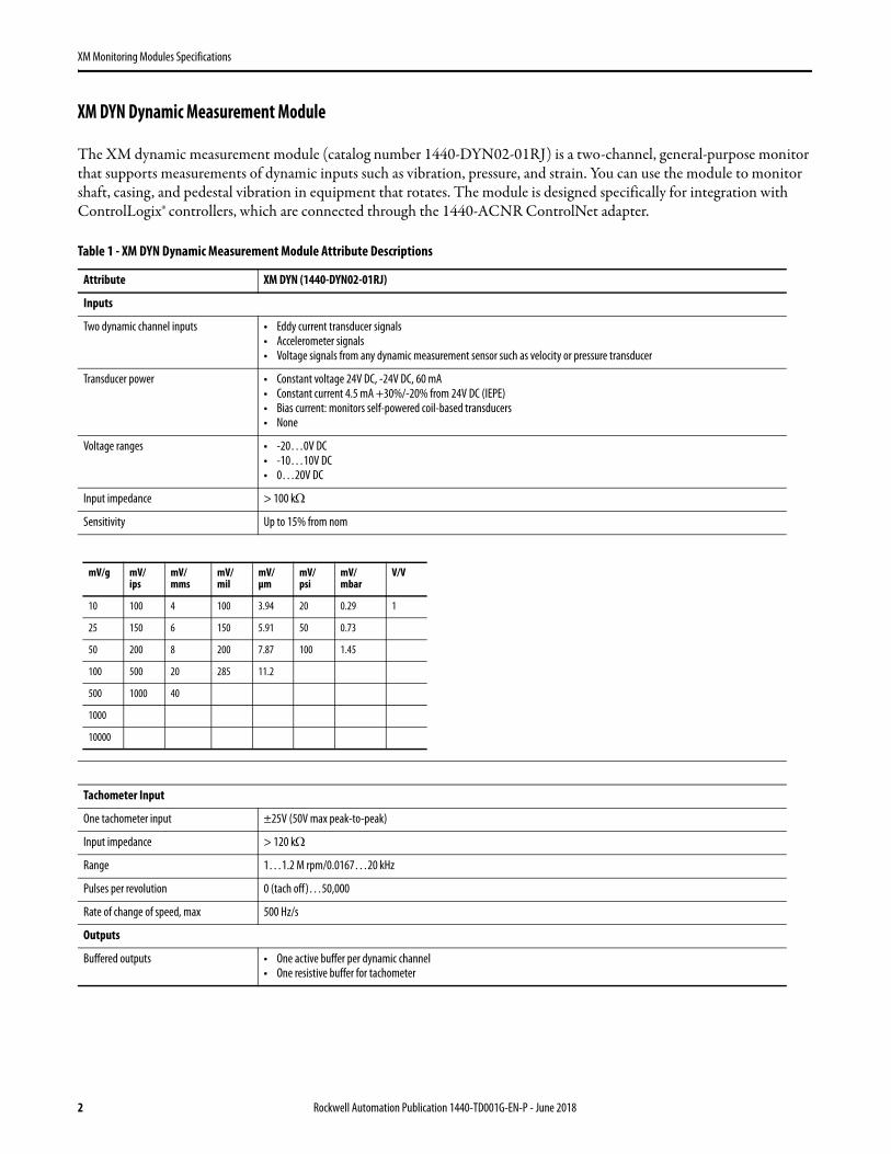
XM DYN Dynamic Measurement Module
The XM dynamic measurement module (catalog number 1440-DYN02-01RJ) is a two-channel, general-purpose monitor that supports measurements of dynamic inputs such as vibration, pressure, and strain. You can use the module to monitor shaft, casing, and pedestal vibration in equipment that rotates. The module is designed specifically for integration with ControlLogix® controllers, which are connected through the 1440-ACNR ControlNet adapter.
Table 1 - XM DYN Dynamic Measurement Module Attribute Descriptions
Attribute XM DYN (1440-DYN02-01RJ)
Inputs
Two dynamic channel inputs • Eddy current transducer signals• Accelerometer signals• Voltage signals from any dynamic measurement sensor such as velocity or pressure transducer
Transducer power • Constant voltage 24V DC, -24V DC, 60 mA• Constant current 4.5 mA +30%/-20% from 24V DC (IEPE)• Bias current: monitors self-powered coil-based transducers• None
Voltage ranges • -20…0V DC• -10…10V DC• 0…20V DC
Input impedance > 100 k
Sensitivity Up to 15% from nom
Tachometer Input
One tachometer input ±25V (50V max peak-to-peak)
Input impedance > 120 k
Range 1…1.2 M rpm/0.0167…20 kHz
Pulses per revolution 0 (tach off)…50,000
Rate of change of speed, max 500 Hz/s
Outputs
Buffered outputs • One active buffer per dynamic channel• One resistive buffer for tachometer
mV/g mV/ips
mV/mms
mV/mil
mV/μm
mV/psi
mV/mbar
V/V
10 100 4 100 3.94 20 0.29 1
25 150 6 150 5.91 50 0.73
50 200 8 200 7.87 100 1.45
100 500 20 285 11.2
500 1000 40
1000
10000
2 Rockwell Automation Publication 1440-TD001G-EN-P - June 2018

XM Monitoring Modules Specifications
Indicators
Status indicators • Module• Network• Channel 0• Channel 1• Tachometer• Setpoint multiplier• Virtual relay
Communication
XM bus • Autobaud 125 Kbps, 250 Kbps, or 500 Kbps• Max distance: 10 m (32.81 ft)• Node number that is mechanically set to simplify installation and commissioning• Customizable poll assembly optimizes space utilization within scanner• Logix Controller integration over the ControlNet network Via 1440-ACNR Adapter
Signal Conditioning
Sampling mode • Selectable per channel• Asynchronous
– FMAX: 1 Hz…20 kHz• Synchronous
– FMAX: 10 < Orders x Speed (Hz) < 5000– Order range: 4…200– Min FMAX: 10 Hz– Max FMAX: 5000 Hz
Resolution • A/D conversion: 24 bits• Dynamic range: 80 dBfs (0.01% fs), 90 dBfs, typical
FFT lines 100, 200, 400, 800
Integration None, single, or double
High pass analog filters • -3 dB corners: 0.2, 1, 5, 10, 40 HzRoll off: -30 dB/octave for the 0.2 Hz filter, otherwise 24 dB/octave• Spike Energy• gSE HPF: 200, 500, 1000, 2000, 5000 HzRoll off: -12 dB/octave
Low pass filter • Applied to integrated acceleration measurements• -6 dB corner: 2 kHzRoll off: -12 dB/octave
Units g, ips, mm/s, mils, μm, PSI, mbar, volt
Measurements
Types • FFT and time waveform• Asynchronous or synchronous
Real time Overall• RMS• Peak (true or calculated)• Peak-to-peak (true or calculated)• Optional low pass filter
– -3 dB corner: 200 Hz…20 kHz– Roll off: -24 dB/octave
• Gap (or transducer bias voltage)• Speed• SMAX magnitude• SMAX phase
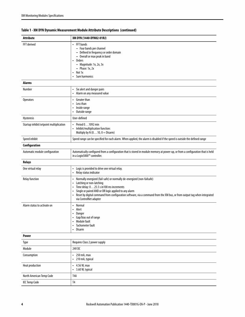
Table 1 - XM DYN Dynamic Measurement Module Attribute Descriptions (continued)
Attribute XM DYN (1440-DYN02-01RJ)
Rockwell Automation Publication 1440-TD001G-EN-P - June 2018 3
XM Monitoring Modules Specifications
FFT derived • FFT bands– Four bands per channel– Defined in frequency or order domain– Overall or max peak in band
• Orders– Magnitude: 1x, 2x, 3x– Phase: 1x, 2x
• Not 1x• Sum harmonics
Alarms
Number • Six alert and danger pairs• Alarm on any measured value
Operators • Greater than• Less than• Inside range• Outside range
Hysteresis User-defined
Startup inhibit/setpoint multiplication • Period 0…1092 min• Inhibit/multiplication function:
Multiply by N (0…10, 0 = Disarm)
Speed inhibit Speed range can be specified for each alarm. When applied, the alarm is disabled if the speed is outside the defined range
Configuration
Automatic module configuration Automatically configured from a configuration that is stored in module memory at power-up, or from a configuration that is held in a Logix5000™ controller.
Relays
One virtual relay • Logic is provided to drive one virtual relay. • Relay status indicator
Relay function • Normally energized (fail-safe) or normally de-energized (non-failsafe)• Latching or non-latching• Time delay: 0…25.5 s in100 ms increments• Single or paired AND or OR logic applied to any alarm• Reset by digital command from configuration software, via a command from the XM bus, or from output tag when integrated
via ControlNet adapter
Alarm status to activate on • Normal• Alert• Danger• Gap/bias out of range• Module fault• Tachometer fault• Disarm
Power
Type Requires Class 2 power supply
Module 24V DC
Consumption • 250 mA, max• 210 mA, typical
Heat production • 4.56 W, max• 3.60 W, typical
North American Temp Code T4A
IEC Temp Code T4
Table 1 - XM DYN Dynamic Measurement Module Attribute Descriptions (continued)
Attribute XM DYN (1440-DYN02-01RJ)
4 Rockwell Automation Publication 1440-TD001G-EN-P - June 2018
XM Monitoring Modules Specifications
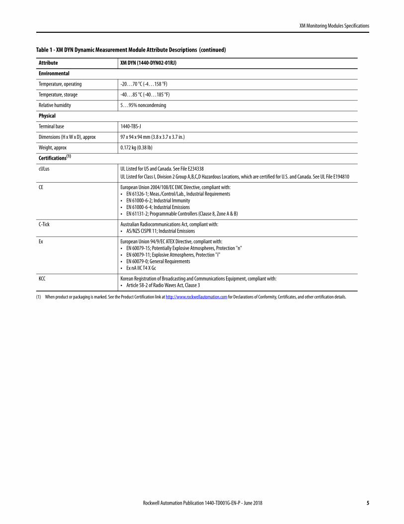
Environmental
Temperature, operating -20…70 °C (-4…158 °F)
Temperature, storage -40…85 °C (-40…185 °F)
Relative humidity 5…95% noncondensing
Physical
Terminal base 1440-TBS-J
Dimensions (H x W x D), approx 97 x 94 x 94 mm (3.8 x 3.7 x 3.7 in.)
Weight, approx 0.172 kg (0.38 lb)
Certifications(1)
cULus UL Listed for US and Canada. See File E234338UL Listed for Class I, Division 2 Group A,B,C,D Hazardous Locations, which are certified for U.S. and Canada. See UL File E194810
CE European Union 2004/108/EC EMC Directive, compliant with:• EN 61326-1; Meas./Control/Lab., Industrial Requirements• EN 61000-6-2; Industrial Immunity• EN 61000-6-4; Industrial Emissions• EN 61131-2; Programmable Controllers (Clause 8, Zone A & B)
C-Tick Australian Radiocommunications Act, compliant with:• AS/NZS CISPR 11; Industrial Emissions
Ex European Union 94/9/EC ATEX Directive, compliant with:• EN 60079-15; Potentially Explosive Atmospheres, Protection "n"• EN 60079-11; Explosive Atmospheres, Protection "i"• EN 60079-0; General Requirements• Ex nA IIC T4 X Gc
KCC Korean Registration of Broadcasting and Communications Equipment, compliant with: • Article 58-2 of Radio Waves Act, Clause 3
(1) When product or packaging is marked. See the Product Certification link at http://www.rockwellautomation.com for Declarations of Conformity, Certificates, and other certification details.
Table 1 - XM DYN Dynamic Measurement Module Attribute Descriptions (continued)
Attribute XM DYN (1440-DYN02-01RJ)
Rockwell Automation Publication 1440-TD001G-EN-P - June 2018 5

XM Monitoring Modules Specifications
XM-124 Standard Dynamic Measurement Module
The XM-124 module (catalog number 1440-SDM02-01RA) is a two-channel, general-purpose monitor that supports dynamic measurements such as vibration, pressure, strain, and spike energy (gSE). The module also supports static (DC) thrust and eccentricity measurements.
The XM-124 consolidates and improves on most of the functionality that is provided by the earlier XM-120, XM-120E, XM-121, XM-122 and XM-123 modules. It also provides the same basic, single-channel, thrust measurement as the XM-320 module. The XM-124 is suitable for monitoring almost any rotating machine, including steam turbines, aeroderivative and industrial gas turbines, hydro turbines, motors, pumps, fans, compressors, and gearboxes.
Table 2 - XM-124 Standard Dynamic Measurement Module Attribute Descriptions
Attribute XM-124 (1440-SDM02-01RA)
Inputs
Two dynamic channel inputs • Eddy current transducer signals• Accelerometer signals• Voltage signals from any dynamic measurement device, such as a velocity or pressure transducer
Transducer power • Constant voltage: 24V DC, -24V DC, 40 mA• Constant current 4.5 mA ± 30% / -20% from 24V DC (IEPE)• None (voltage input)• Tachometer can be powered, constant voltage, or configured as voltage input
Voltage range • -20…0V DC• -10…10V DC• 0…20V DC
Input impedance > 100 k
Sensitivity Up to 15% from nom
Tachometer Input
One tachometer input • ±25V (50V max peak-to-peak)• 1…50,000 events/revolution
Input impedance > 120 k
Range • 1…1,200,000 rpm• 0.0167…20,000 Hz
Pulses per revolution 0 (tach off)…50,000
Rate of change of speed, max 500 Hz/s
mV/g mV/ips
mV/mms
mV/mil
mV/μm
mV/psi
mV/mbar
V/V
10 100 4 100 3.94 20 0.29 1
25 150 6 150 5.91 50 0.73
50 200 8 200 7.87 100 1.45
100 500 20 285 11.2
500 1000 40
1000
10000
6 Rockwell Automation Publication 1440-TD001G-EN-P - June 2018

XM Monitoring Modules Specifications
Outputs
4…20 mA • Each output is independently programmed to represent any measured parameter, from either channel• Two isolated outputs• 300 max load
Buffered outputs • One active buffer per dynamic channel• One resistive buffer for tachometer
Indicators
Status indicators • Module• Network• Channel 1• Channel 2• Tachometer• Setpoint multiplier• Virtual relay
Communication
DeviceNet network • Standard DeviceNet protocol for all functions (not power—module power is provided independently)• Available EDS file supports most DeviceNet compliant systems• Communication rate that is set automatically by bus master to 125 Kbps, 250 Kbps, or 500 Kbps• Configurable I/O Poll Response message helps optimize space utilization within scanner input tables:
– Selectable poll response assembly– Selectable poll response size (bytes)
Serial • RS-232 via mini-connector or terminal base unit• Communication rate that is fixed at 19.2 Kbps• Local configuration via the Serial Configuration Utility
Signal Conditioning
Sampling mode • Selectable per channel• Dynamic Measurements
– Asynchronous FMAX: 1 Hz…20 kHz– Synchronous
• Order range: 4…200– Min FMAX: 10 Hz– Max FMAX: 5000 Hz, Measured: Orders x Speed (Hz)
• Spike Energy
• Static Measurements– Eccentricity Peak-to-Peak Eccentricity
• Thrust Normal mode (single channel measurement)
Resolution • A/D conversion: 24 bits• Dynamic range: 80 dBfs (0.01% fs), 90 dBfs, typical
FFT lines 100, 200, 400, 800, 1600
Integration None, single, or double
High pass analog filters • -3 dB corners: 0.2, 1, 5, 10, 40 HzRoll off: -30 dB/octave for the 0.2 Hz filter, otherwise 24 dB/octave
Low pass analog filter • Applied to integrated acceleration measurements• -3 dB corner: 5 kHzRoll off: -18 dB/octave
Table 2 - XM-124 Standard Dynamic Measurement Module Attribute Descriptions (continued)
Attribute XM-124 (1440-SDM02-01RA)
Rockwell Automation Publication 1440-TD001G-EN-P - June 2018 7

XM Monitoring Modules Specifications
Low pass digital filter Independently configured per channel• Optional Overall LP Filter• 100…20000 Hz • Spike Energy• Spectra FMAX: 10…5000 Hz• Roll Off: -24 dB/octave
Tracking digital filter Independently configured per channel• Tracked speed multiple: 0.1…20.0 times the measured (tachometer) rpm• Constant Q: 1…200• Constant bandwidth: 0.1…25 Hz• Roll off: -36 dB/octave, typical
Band pass digital filter Independently configured per channel• Frequency, min 25…1000 Hz• Frequency, max 100…5500 Hz• Roll off: -60 dB/octave
Units g, ips, mm/s, mils, μm, PSI, mbar, volt
Data(1)
Complex data • Spectra (synchronous or asynchronous)• Waveform (synchronous or asynchronous)• Simultaneous waveforms (synchronous)• gSE Spectra
Accuracy, min • ±1% of full scale range for the channel• ±1% of alarm setpoint for speed
Measurements(2)
Types • FFT and time waveform• Asynchronous or synchronous
Real time • Overall• RMS• Peak (true or calculated)• Peak-to-peak (true or calculated)• gSE(5)
• Optional low pass filter– -3 dB corner: 200 Hz…20 kHz– Roll off: -24 dB/octave
• Gap (or transducer bias voltage)• Speed• SMAX magnitude• SMAX phase• Band pass filter value• Tracking filter magnitude• Tracking filter phase• Thrust position• Eccentricity
FFT derived • FFT bands– Four bands per channel– Defined in frequency or order domain– Overall or max peak in band
• Orders– Magnitude: 1x, 2x, 3x– Phase: 1x, 2x
• Not 1x• Sum harmonics
Table 2 - XM-124 Standard Dynamic Measurement Module Attribute Descriptions (continued)
Attribute XM-124 (1440-SDM02-01RA)
8 Rockwell Automation Publication 1440-TD001G-EN-P - June 2018

XM Monitoring Modules Specifications
Data Buffers
Delta time buffer • Number of records: 2048• Delta time interval: 1…3600 s• Trigger mode: Relay is activated or trigger event (such as DeviceNet command from a controller or host)
Delta rpm buffer • Number of records: 512• Delta speed interval: 1…3600 rpm• Trigger mode: Startup collects data in increasing rpm direction only; coast-down collects data in both
increasing and decreasing directions• The data that is collected in the buffer is user configurable and can contain up to 16 of the measurements
Spectra or waveform Saved upon same trigger as delta time buffer
Alarms
Number Sixteen alarm and danger pairs
Alarm parameters Any measured parameter
Operators • Greater than• Less than• Inside range• Outside range
Hysteresis User configurable in software
Startup inhibit/setpoint multiplication • Period: 0…1092 min, adjustable in 0.1 min increments• Inhibit/multiplication function:
Multiply by N (0…10, 0 = Disarm)
Speed inhibit A speed range can be specified for each alarm. When applied, the alarm is disabled when speed is outside of the defined range.
Relays
Number • Single on-board relay, Single Pole Single Throw (SPST), one Form A• Four additional DPDT relays when interconnected to an XM-441 expansion relay module, or• Four virtual relays whose status can be used by remote control systems or the XM-440 master relay module,
also four DPDT relays
Rating (resistive) • Capacity, nominal: 1.5 A @ 24V DC• Capacity, min 100 μA @ 100 mV DC• Power, max 41.4 W• Voltage, max 27.6V DC• Current, max 1.5 A
Expected life (min operations) • Mechanical: 2x10⁷
• Electrical @ 20 cpm– 1.5 A, 24V DC: 10^5
Failsafe • Normally energized (fail-safe) or• Normally de-energized (non-fail-safe)
Latching • Latching• Non-latching
Time delay 0…25.5 s, adjustable in 100 ms increments
Logic Single or paired AND or OR logic applied to any alarm
Reset • Local reset switch on top of module• Remote reset switch that is wired to terminal base• Digital reset command via serial or DeviceNet interface
Table 2 - XM-124 Standard Dynamic Measurement Module Attribute Descriptions (continued)
Attribute XM-124 (1440-SDM02-01RA)
Rockwell Automation Publication 1440-TD001G-EN-P - June 2018 9

XM Monitoring Modules Specifications
Activation on • Alarm status– Normal– Alert– Danger– Disarm– Transducer fault– Module fault– Tacho fault
Peak speed capture The XM-124 retains the value of the highest speed that is observed since module power was cycled or the peak speed value was manually reset
Configuration
Nonvolatile configuration • A copy of the module configuration is retained in nonvolatile memory from which the configuration is loaded upon powerup
• The configuration that is stored in nonvolatile memory can be deleted only by a module-reset command that is sent via a serial interface, using the Serial Configuration Utility or via a DeviceNet interface from any compliant software application
Module
Power supply • 24V DC• 350 mA• Requires Class 2/SELV/PELV power supply
Power dissipation 8.7 W, max
Isolation voltage • 50V (continuous), basic insulation type between uninsulated live parts and the enclosure with the relay contacts open and closed
• Type tested at 707V DC for 60 s between uninsulated live parts and the enclosure with the relay contacts open and closed
• Type tested at 707V DC for 60 s between supply and output terminals
Wiring category(3) • 2 - on signal ports• 1 - on power and relay ports• 2 - on DeviceNet ports• 3 - on serial ports
North American temp code T5
IEC temp code T4
Environmental
Temperature, operatingIEC 60068-2-1 (Test Ad, Operating Cold),IEC 60068-2-2 (Test Bd, Operating Dry Heat),IEC 60068-2-14 (Test Nb, Operating Thermal Shock)
-20…65 °C (-4…149 °F)
Temperature, surrounding air max 65 °C (149 °F)
Temperature, storageIEC 60068-2-1 (Test Ab, Unpackaged Nonoperating Cold),IEC 60068-2-2 (Test Bb, Unpackaged Nonoperating Dry Heat),IEC 60068-2-14 (Test Na, Unpackaged Nonoperating Thermal Shock)
-40…85 °C (-40…185 °F)
Relative humidityIEC 60068-2-30 (Test Db, Unpackaged Damp Heat)
5…95% noncondensing
VibrationIEC 60068-2-6 (Test Fc, Operating)
5 g @ 10…500 Hz
Shock, operatingIEC 60068-2-27 (Test Ea, Unpackaged Shock)
15 g
Shock, nonoperatingIEC 60068-2-27 (Test Ea, Unpackaged Shock)
30 g
EmissionsCISPR11 (IEC 61000-6-4)
Class A
Table 2 - XM-124 Standard Dynamic Measurement Module Attribute Descriptions (continued)
Attribute XM-124 (1440-SDM02-01RA)
10 Rockwell Automation Publication 1440-TD001G-EN-P - June 2018

XM Monitoring Modules Specifications
ESD immunityIEC 61000-4-2
• 6 kV contact discharges• 8 kV air discharges
Radiated RF immunityIEC 61000-4-3
• 10V/m with 1 kHz sine-wave 80% AM from 80…2000 MHz• 10V/m with 200 Hz 50% pulse 100% AM at 900 MHz• 10V/m with 200 Hz 50% pulse 100% AM at 1890 MHz• 3V/m with 1 kHz sine-wave 80% AM from 2000…2700 MHz
EFT/B immunityIEC 61000-4-4
• ±3 kV at 5 kHz on power ports• ±3 kV at 5 kH on signal ports• ±3 kV at 5 kHz on DeviceNet ports
Surge transient immunityIEC 61000-4-5
• ±1 kV line-line (DM) and ±2 kV line-earth (CM) on power and relay ports• ±2 kV line-earth (CM) on shielded signal ports• ±2 kV line-earth (CM) on DeviceNet ports
Conducted RF immunityIEC 61000-4-6
10V rms with 1 kHz sine-wave 80% AM from 150 kHz…80 MHz
Enclosure type rating None (open-style)
Physical
Terminal base 1440-TB-A (XM-940) Series C
Dimensions (H x W x D), approx 97 x 94 x 94 mm, (3.8 x 3.7 x 3.7 in.)
Weight • Module: 0.172 kg (0.38 lb)• Terminal base: 0.172 kg (0.38 lb)
Certifications(4)
c-UL-us UL Listed for Class I, Division 2 Group A,B,C,D Hazardous Locations, certified for U.S. and Canada. See UL File E194810.
CE European Union 2004/108/EC EMC Directive, compliant with:• EN 61326-1; Meas./Control/Lab., Industrial Requirements• EN 61000-6-2; Industrial Immunity• EN 61000-6-4; Industrial Emissions• EN 61131-2; Programmable Controllers (Clause 8, Zone A & B)
RCM Australian Radiocommunications Act, compliant with:• AS/NZS CISPR 11; Industrial Emissions
Ex European Union 94/9/EC ATEX Directive, compliant with:• EN 60079-15; Potentially Explosive Atmospheres, Protection "n"• EN 60079-11; Explosive Atmospheres, Protection "i"• EN 60079-0; General Requirements • II 3 G Ex nAC• [ic] IIC T4 Gc X
KC Korean Registration of Broadcasting and Communications Equipment, compliant with:• Article 58-2 of Radio Waves Act, Clause 3
(1) Complex data is available when the channel is configured for dynamic measurements.
(2) Measurement availability is dependent on channel configuration.
(3) Use this Conductor Category information for planning the conductor routing. See Industrial Automation Wiring and Grounding Guidelines, publication 1770-4.1.
(4) When product or packaging is marked. See the Product Certification link at http://www.rockwellautomation.com for Declarations of Conformity, Certificates, and other certification details.
(5) gSE Measurements can be configured to update continuously, or to alternate with standard acceleration or velocity measurements. The gSE Overall updates in "real-time" only when configured for continuous update.
Table 2 - XM-124 Standard Dynamic Measurement Module Attribute Descriptions (continued)
Attribute XM-124 (1440-SDM02-01RA)
Rockwell Automation Publication 1440-TD001G-EN-P - June 2018 11

XM Monitoring Modules Specifications
XM-220 Dual Speed Module
The XM-220 module (catalog number 1440-SPD02-01RB) measures speed, rotor acceleration, and peak speed and can detect zero speed, locked rotor, and reverse rotation. The module can also serve as a component of an Electronic Overspeed Detection System (EODS).
Table 3 - XM-220 Dual Speed Module
Attribute XM-220 (1440-SPD02-01RB)
Inputs
Two tachometer inputs • ±25V (50V max peak-to-peak)• Eddy current transducer signals• Magnetic pickups• TTL output devices
Input impedance 120 k min
Speed/frequency range • 1…1,200,000 rpm• 0.0167…20,000 Hz
Speed measurement error • 1…240 rpm: ±0.2 rpm• 241…12,000 rpm: ±2 rpm• 12,001…20,400 rpm: ±5 rpm• 20,401…120,000 rpm: ±20 rpm • 120,001…360,000 rpm: ±50 rpm• 360,001…1,200,000 rpm: ±160 rpm
Outputs
4…20 mA outputs • Each output is independently programmed to represent speed or acceleration, from either channel• Two isolated outputs• 300 max load• One active buffer per input channel
Buffered outputs • Output range configurable by wiring: – -24…9V– -5…24V– -5…9V
• Third buffered output available when the module is configured for single redundant channel mode. Outputs a CMOS (0…5V) level square-wave that corresponds to the active input signal
Sensor Fault Detection
Eddy current transducer Bias voltage is compared with the fault limits
Magnetic pickups A current source is available for biasing passive magnetic pickups to detect open or short circuits
Indicators
Status indicators • Module - red/green• Network - red/green• Channel 1 - yellow/red• Channel 2 - yellow/red• Startup - yellow• Relay - red• AUX - reserved for future use
12 Rockwell Automation Publication 1440-TD001G-EN-P - June 2018

XM Monitoring Modules Specifications
Communication
DeviceNet network • Standard DeviceNet protocol for all functions (not power—module power is provided independently)
• Available EDS file supports most DeviceNet compliant systems• Communication rate that is automatically set by bus master to 125 Kbps, 250 Kbps, or 500 Kbps• Configurable I/O Poll Response message helps optimize space utilization within scanner input tables:
– Selectable poll response assembly– Selectable poll response size (bytes)
Serial • RS-232 via mini-connector or terminal base unit• Communication rate that is fixed at 19.2 Kbps• Local configuration via the Serial Configuration Utility
Measurements
Units • rpm• Direction of rotation• Acceleration in rpm/min
Measured parameters • Forward• Reverse• rpm• Direction of rotation• Acceleration in rpm/min
Peak speed capture The module retains the value of the highest speed that is observed since module power was cycled or the peak speed value was manually reset
Measurement Modes
Dual channel Two sensors are used independently to perform two separate speed, acceleration and peak speed measurements
Single redundant channel One sensor is used to perform the speed, acceleration, and peak speed measurements. If the current sensor fails, the module automatically switches to the second (redundant) sensor
Reverse rotation Two sensors are used to monitor both speed and direction. The two sensors must be mounted out of phase from each other so that the rotational direction can be determined by monitoring which sensor the shaft keyway passes first
Alarms
Number Eight alarms, which are fixed per channel
Alarm parameters Alarm and danger pair that is provided for each of:• Speed• Acceleration• Zero speed• Locked rotor
Operators • Greater than• Less than• Inside range• Outside range
Hysteresis User configurable in software
Relays
Number • Single on-board relay, two sets of contacts - DPDT (two Form C)• Four additional relays when interconnected to an XM-441 expansion relay module, or • Four virtual relays whose status can be used by remote control systems or the XM-440 master relay
module
Table 3 - XM-220 Dual Speed Module (continued)
Attribute XM-220 (1440-SPD02-01RB)
Rockwell Automation Publication 1440-TD001G-EN-P - June 2018 13
XM Monitoring Modules Specifications
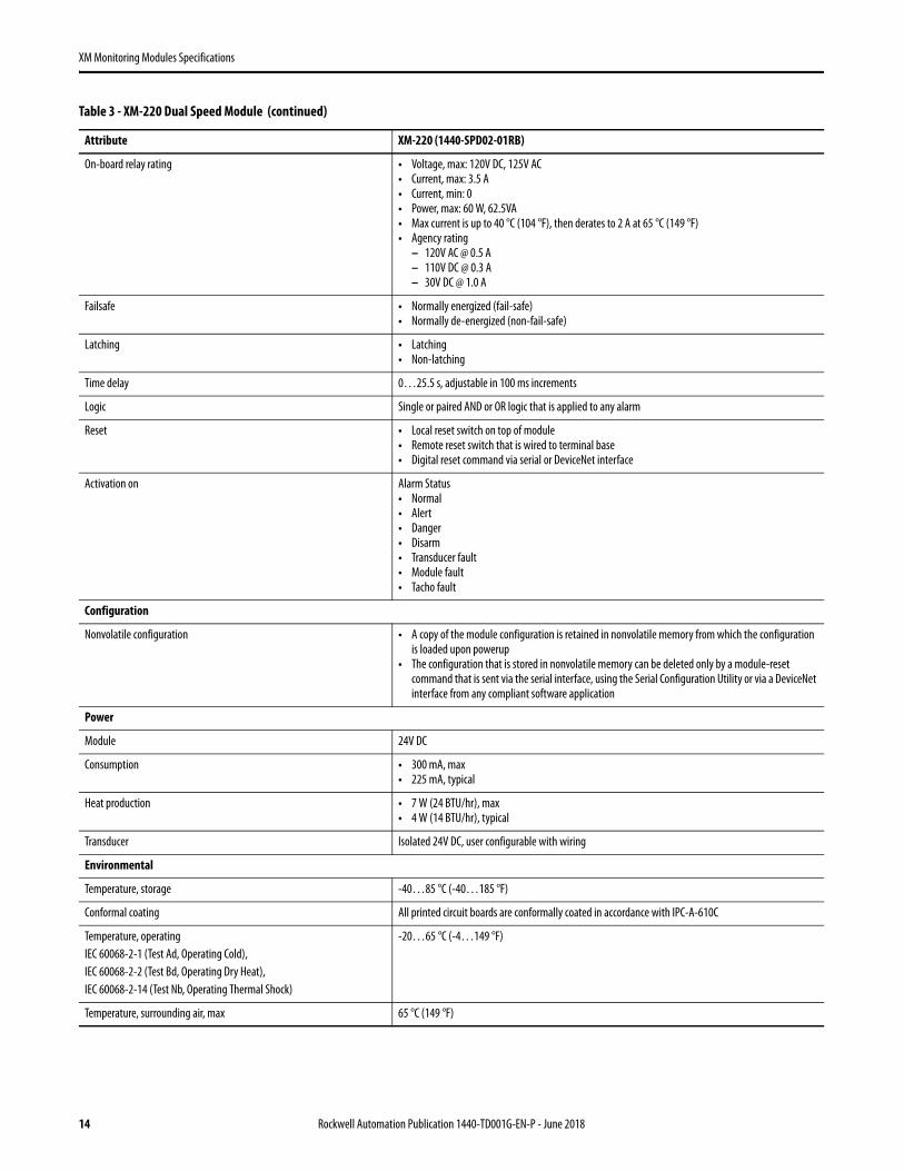
On-board relay rating • Voltage, max: 120V DC, 125V AC• Current, max: 3.5 A• Current, min: 0• Power, max: 60 W, 62.5VA• Max current is up to 40 °C (104 °F), then derates to 2 A at 65 °C (149 °F)• Agency rating
– 120V AC @ 0.5 A– 110V DC @ 0.3 A– 30V DC @ 1.0 A
Failsafe • Normally energized (fail-safe)• Normally de-energized (non-fail-safe)
Latching • Latching• Non-latching
Time delay 0…25.5 s, adjustable in 100 ms increments
Logic Single or paired AND or OR logic that is applied to any alarm
Reset • Local reset switch on top of module• Remote reset switch that is wired to terminal base• Digital reset command via serial or DeviceNet interface
Activation on Alarm Status• Normal• Alert• Danger• Disarm• Transducer fault• Module fault• Tacho fault
Configuration
Nonvolatile configuration • A copy of the module configuration is retained in nonvolatile memory from which the configuration is loaded upon powerup
• The configuration that is stored in nonvolatile memory can be deleted only by a module-reset command that is sent via the serial interface, using the Serial Configuration Utility or via a DeviceNet interface from any compliant software application
Power
Module 24V DC
Consumption • 300 mA, max• 225 mA, typical
Heat production • 7 W (24 BTU/hr), max• 4 W (14 BTU/hr), typical
Transducer Isolated 24V DC, user configurable with wiring
Environmental
Temperature, storage -40…85 °C (-40…185 °F)
Conformal coating All printed circuit boards are conformally coated in accordance with IPC-A-610C
Temperature, operatingIEC 60068-2-1 (Test Ad, Operating Cold),IEC 60068-2-2 (Test Bd, Operating Dry Heat),IEC 60068-2-14 (Test Nb, Operating Thermal Shock)
-20…65 °C (-4…149 °F)
Temperature, surrounding air, max 65 °C (149 °F)
Table 3 - XM-220 Dual Speed Module (continued)
Attribute XM-220 (1440-SPD02-01RB)
14 Rockwell Automation Publication 1440-TD001G-EN-P - June 2018
XM Monitoring Modules Specifications
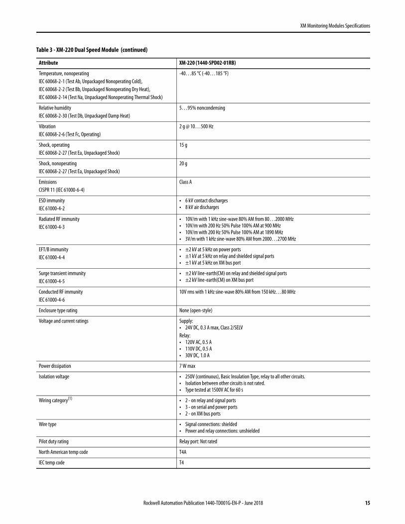
Temperature, nonoperatingIEC 60068-2-1 (Test Ab, Unpackaged Nonoperating Cold),IEC 60068-2-2 (Test Bb, Unpackaged Nonoperating Dry Heat),IEC 60068-2-14 (Test Na, Unpackaged Nonoperating Thermal Shock)
-40…85 °C (-40…185 °F)
Relative humidityIEC 60068-2-30 (Test Db, Unpackaged Damp Heat)
5…95% noncondensing
VibrationIEC 60068-2-6 (Test Fc, Operating)
2 g @ 10…500 Hz
Shock, operatingIEC 60068-2-27 (Test Ea, Unpackaged Shock)
15 g
Shock, nonoperatingIEC 60068-2-27 (Test Ea, Unpackaged Shock)
20 g
EmissionsCISPR 11 (IEC 61000-6-4)
Class A
ESD immunityIEC 61000-4-2
• 6 kV contact discharges• 8 kV air discharges
Radiated RF immunityIEC 61000-4-3
• 10V/m with 1 kHz sine-wave 80% AM from 80…2000 MHz• 10V/m with 200 Hz 50% Pulse 100% AM at 900 MHz• 10V/m with 200 Hz 50% Pulse 100% AM at 1890 MHz• 3V/m with 1 kHz sine-wave 80% AM from 2000…2700 MHz
EFT/B immunityIEC 61000-4-4
• ±2 kV at 5 kHz on power ports• ±1 kV at 5 kHz on relay and shielded signal ports• ±1 kV at 5 kHz on XM bus port
Surge transient immunityIEC 61000-4-5
• ±2 kV line-earth(CM) on relay and shielded signal ports• ±2 kV line-earth(CM) on XM bus port
Conducted RF immunityIEC 61000-4-6
10V rms with 1 kHz sine-wave 80% AM from 150 kHz…80 MHz
Enclosure type rating None (open-style)
Voltage and current ratings Supply:• 24V DC, 0.3 A max, Class 2/SELVRelay:• 120V AC, 0.5 A• 110V DC, 0.5 A• 30V DC, 1.0 A
Power dissipation 7 W max
Isolation voltage • 250V (continuous), Basic Insulation Type, relay to all other circuits.• Isolation between other circuits is not rated.• Type tested at 1500V AC for 60 s
Wiring category(1) • 2 - on relay and signal ports• 3 - on serial and power ports• 2 - on XM bus ports
Wire type • Signal connections: shielded• Power and relay connections: unshielded
Pilot duty rating Relay port: Not rated
North American temp code T4A
IEC temp code T4
Table 3 - XM-220 Dual Speed Module (continued)
Attribute XM-220 (1440-SPD02-01RB)
Rockwell Automation Publication 1440-TD001G-EN-P - June 2018 15

XM Monitoring Modules Specifications
Physical
Terminal base 1440-TB-B
Dimensions (H x W x D), approx 97 x 94 x 94 mm (3.8 x 3.7 x 3.7 in.)
Certification(2)
(when product is marked)
c-CSA-us CSA Certified Process Control Equipment for Class I, Division 2 Group A,B,C,D Hazardous Locations, certified for US and Canada. See CSA File 150115.
CE European Union 2004/108/EC EMC Directive, compliant with:• EN 61326-1; Meas./Control/Lab., Industrial Requirements• EN 61000-6-2; Industrial Immunity• EN 61000-6-4; Industrial Emissions• EN 61131-2; Programmable Controllers (Clause 8, Zone A & B)European Union 2006/95/EC LVD, compliant with:EN 61131-2; Programmable Controllers (Clause 11)
C-Tick Australian Radiocommunications Act, compliant with:• AS/NZS CISPR 11; Industrial Emissions
Ex European Union 94/9/EC ATEX Directive, compliant with:• EN 60079-15; Potentially Explosive Atmospheres, Protection "n"• EN 60079-11; Explosive Atmospheres, Protection "i"• EN 60079-0; General Requirements• II 3 G Ex nAC [ic] IIC T4X Gc• when used at or below 60V AC or 75V DC
KC Korean Registration of Broadcasting and Communications Equipment, compliant with:• Article 58-2 of Radio Waves Act, Clause 3
(1) Use this Conductor Category information for planning the conductor routing. See Industrial Automation Wiring and Grounding Guidelines, publication 1770-4.1.
(2) See the Product Certification link at http://www.rockwellautomation.com for Declarations of Conformity, Certificates, and other certification details.
Table 3 - XM-220 Dual Speed Module (continued)
Attribute XM-220 (1440-SPD02-01RB)
16 Rockwell Automation Publication 1440-TD001G-EN-P - June 2018

XM Monitoring Modules Specifications
XM-441 Expansion Relay Module
The XM-441 expansion relay (catalog number 1440-REX00-04RD) adds four relays to any XM measurement module or to the XM-440 master relay.
Table 4 - XM-441 Expansion Relay Module Attribute Descriptions
Attribute XM-441 (1440-REX00-04RD)
Indicators
Status indicators • Module power -green• Relay 1 - red• Relay 2 - red• Relay 3 - red• Relay 4 - red
Communication
Host communication The XM-441 module communicates to a host module via the side connector of the terminal base. If the host is an XM-440 master relay module, then you can place two XM-441 modules immediately to the right of the XM-440 module. All XM measurement modules support just one expansion module, which must be connected directly to and on the right of the host module
Relays
Number Four relays, two sets of contacts each - DPDT (two Form C)
Contacts 250V AC, 50/60 Hz @ 3 A resistive
Failsafe • Normally energized (fail-safe)• Normally de-energized (non-failsafe)
Other features These features are managed by the host XM module:• Latching• Time delay• Logic• Reset• Activation
Environmental
Temperature, storage -40…85 °C (-40…185 °F)
Conformal coating All printed circuit boards are conformally coated in accordance with IPC-A-610C
Temperature, operating IEC 60068-2-1 (Test Ad, Operating Cold), IEC 60068-2-2 (Test Bd, Operating Dry Heat), IEC 60068-2-14 (Test Nb, Operating Thermal Shock)
-20…65 °C (-4…149 °F)
Temperature, surrounding air, max. 65 °C (149 °F)
Temperature, nonoperating IEC 60068-2-1 (Test Ab, Unpackaged Nonoperating Cold), IEC 60068-2-2 (Test Bb, Unpackaged Nonoperating Dry Heat), IEC 60068-2-14 (Test Na, Unpackaged Nonoperating Thermal Shock)
-40…85 °C (-40…185 °F)
Relative humidity IEC 60068-2-30 (Test Db, Unpackaged Damp Heat)
5…95% noncondensing
Vibration IEC 60068-2-6 (Test Fc, Operating)
2 g @ 10…500 Hz
Shock, operating IEC 60068-2-27 (Test Ea, Unpackaged Shock)
15 g
Shock, nonoperating IEC 60068-2-27 (Test Ea, Unpackaged Shock)
20 g
Rockwell Automation Publication 1440-TD001G-EN-P - June 2018 17
XM Monitoring Modules Specifications
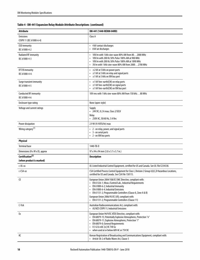
Emissions CISPR 11 (IEC 61000-6-4)
Class A
ESD immunity IEC 61000-4-2
• 4 kV contact discharges• 8 kV air discharges
Radiated RF immunityIEC 61000-4-3
• 10V/m with 1 kHz sine-wave 80% AM from 80…2000 MHz • 10V/m with 200 Hz 50% Pulse 100% AM at 900 MHz • 10V/m with 200 Hz 50% Pulse 100% AM at 1890 MHz • 3V/m with 1 kHz sine-wave 80% AM from 2000…2700 MHz
EFT/B immunityIEC 61000-4-4:
• ±2 kV at 5 kHz on power ports • ±1 kV at 5 kHz on relay and signal ports • ±1 kV at 5 kHz on XM bus port
Surge transient immunityIEC 61000-4-5
• ±1 kV line-earth(CM) on relay ports• ±1 kV line-earth(CM) on signal ports• ±1 kV line-earth(CM) on XM bus port
Conducted RF immunityIEC 61000-4-6
10V rms with 1 kHz sine-wave 80% AM from 150 kHz…80 MHz
Enclosure type rating None (open-style)
Voltage and current ratings Supply• 24V DC, 0.2 A max, Class 2/SELV Relay• 250V AC, 50/60 Hz, 3 A Res
Power dissipation 2.9 W (9.9 BTU/hr) max
Wiring category(1) • 2 - on relay, power, and signal ports• 3 - on serial ports• 2 - on XM bus ports
Physical
Terminal base 1440-TB-D
Dimensions (H x W x D), approx 97 x 94 x 94 mm (3.8 x 3.7 x 3.7 in.)
Certification(2)
(when product is marked)Description
c-UL-us UL Listed Industrial Control Equipment, certified for US and Canada. See UL File E234338.
c-CSA-us CSA Certified Process Control Equipment for Class I, Division 2 Group A,B,C,D Hazardous Locations, certified for US and Canada. See CSA File 150115.
CE European Union 2004/108/EC EMC Directive, compliant with:• EN 61326-1; Meas./Control/Lab., Industrial Requirements• EN 61000-6-2; Industrial Immunity• EN 61000-6-4; Industrial Emissions• EN 61131-2; Programmable Controllers (Clause 8, Zone A & B)European Union 2006/95/EC LVD, compliant with:• EN 61131-2; Programmable Controllers (Clause 11)
C-Tick Australian Radiocommunications Act, compliant with:• AS/NZS CISPR 11; Industrial Emissions
Ex European Union 94/9/EC ATEX Directive, compliant with:• EN 60079-15; Potentially Explosive Atmospheres, Protection "n"• EN 60079-11; Explosive Atmospheres, Protection "i"• EN 60079-0; General Requirements• II 3 G Ex nAC [ic] IIC T4X Gc• when used at or below 60V AC or 75V DC
KC Korean Registration of Broadcasting and Communications Equipment, compliant with:• Article 58-2 of Radio Waves Act, Clause 3
Table 4 - XM-441 Expansion Relay Module Attribute Descriptions (continued)
Attribute XM-441 (1440-REX00-04RD)
18 Rockwell Automation Publication 1440-TD001G-EN-P - June 2018

XM Monitoring Modules Specifications
Wire Type • Signal connections: shielded• Power and Relay connections: unshielded
Pilot Duty Rating Relay ports: Not rated
North American Temp Code T4A
IEC Temp Code T4
(1) Use this Conductor Category information for planning the conductor routing. See Industrial Automation Wiring and Grounding Guidelines, publication 1770-4.1.
(2) See the Product Certification link at http://www.rockwellautomation.com for Declarations of Conformity, Certificates, and other certification details.
Table 4 - XM-441 Expansion Relay Module Attribute Descriptions (continued)
Attribute XM-441 (1440-REX00-04RD)
Rockwell Automation Publication 1440-TD001G-EN-P - June 2018 19

XM Monitoring Modules Specifications
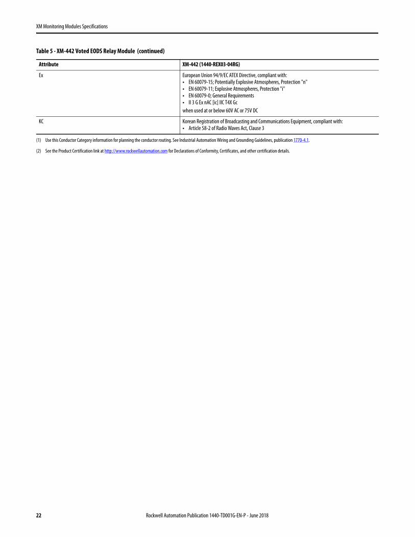
XM-442 Voted EODS Relay Module
The XM-442 module (catalog number 1440-REX03-04RG) combines with three XM-220 modules to provide an API-compliant, triple-redundant Electronic Overspeed Detection System (EODS).
Table 5 - XM-442 Voted EODS Relay Module
Attribute XM-442 (1440-REX03-04RG)
Indicators
Status indicators • Module power - red/green• Shutdown relay - red• Alarm relay - red
Communication
Host communication The XM-442 module communicates to the speed modules connected to it only via the three digital inputs on the front of the terminal base. Power and communication pass through the side connector of the terminal base but are not used by the XM-442 module
Relays
Number Four relays, two sets of contacts each - DPDT (2 Form C)
Contacts • 250V AC, 50/60 Hz @ 3 A resistive• 150V DC, 1.6 A Resistive
Failsafe Normally energized
Latching The shutdown and alarm relays latch when the conditions that activate them are met
Logic • Two-out-of-three• One-out-of-three
Activation Low logic level (< 0.8V) on the overspeed/circuit fault inputs
Reset • Local reset switch on top of module• Remote reset switch that is wired to terminal base
Power
Voltage and current ratings Supply:• 24V DC, 0.2 A max, Class 2/SELVRelay:• 250V AC, 50/60 Hz, 3 A Res• 150V DC, 1.6 A Res
Heat production 2.9 W (9.9 BTU/hr), max
Environmental
Temperature, storage -40…85 °C (-40…185 °F)
Conformal coating All printed circuit boards are conformally coated in accordance with IPC-A-610C
Temperature, operatingIEC 60068-2-1 (Test Ad, Operating Cold),IEC 60068-2-2 (Test Bd, Operating Dry Heat),IEC 60068-2-14 (Test Nb, Operating Thermal Shock)
-20…65 °C (-4…149 °F)
Temperature, surrounding air, max 65 °C (149 °F)
Temperature, nonoperatingIEC 60068-2-1 (Test Ab, Unpackaged Nonoperating Cold),IEC 60068-2-2 (Test Bb, Unpackaged Nonoperating Dry Heat),IEC 60068-2-14 (Test Na, Unpackaged Nonoperating Thermal Shock)
-40…85 °C (-40…185 °F)
Relative humidityIEC 60068-2-30 (Test Db, Unpackaged Damp Heat)
5…95% noncondensing
20 Rockwell Automation Publication 1440-TD001G-EN-P - June 2018

XM Monitoring Modules Specifications
VibrationIEC 60068-2-6 (Test Fc, Operating)
2 g @ 10…500 Hz
Shock, operatingIEC 60068-2-27 (Test Ea, Unpackaged Shock)
15 g
Shock, nonoperatingIEC 60068-2-27 (Test Ea, Unpackaged Shock)
20 g
EmissionsCISPR 11 (IEC 61000-6-4)
Class A
ESD immunityIEC 61000-4-2
• 4 kV contact discharges• 8 kV air discharges
Radiated RF immunityIEC 61000-4-3
• 10V/m with 1 kHz sine-wave 80% AM from 80…2000 MHz• 10V/m with 200 Hz 50% Pulse 100% AM at 900 MHz• 10V/m with 200 Hz 50% Pulse 100% AM at 1890 MHz• 3V/m with 1 kHz sine-wave 80% AM from 2000…2700 MHz
EFT/B immunityIEC 61000-4-4
• ±2 kV at 5 kHz on power ports• ±1 kV at 5 kHz on relay and signal ports• ±1 kV at 5 kHz on XM bus port
Surge transient immunityIEC 61000-4-5
• ±1 kV line-earth(CM) on relay ports• ±1 kV line-earth(CM) on signal ports• ±1 kV line-earth(CM) on XM bus port
Conducted RF immunityIEC 61000-4-6
10V rms with 1 kHz sine-wave 80% AM from 150 kHz…80 MHz
Enclosure type rating None (open-style)
Power dissipation 2.9 W max
Wiring category(1) • 2 - on relay, power, and signal ports• 3 - on serial ports• 2 - on XM bus ports
Wire type • Signal connections: shielded• Power and relay connections: unshielded
Pilot duty rating Relay ports: Not rated
North American temp code T4A
IEC temp code T4
Physical
Terminal base 1440-TB-G
Dimensions (H x W x D), approx 97 x 94 x 94 mm (3.8 x 3.7 x 3.7 in.)
Certification(2) (when product is marked)
c-CSA-us CSA Certified Process Control Equipment for Class I, Division 2 Group A,B,C,D Hazardous Locations, certified for US and Canada. See CSA File 150115.
CE European Union 2004/108/EC EMC Directive, compliant with:• EN 61326-1; Meas./Control/Lab., Industrial Requirements• EN 61000-6-2; Industrial Immunity• EN 61000-6-4; Industrial Emissions• EN 61131-2; Programmable Controllers (Clause 8, Zone A & B)European Union 2006/95/EC LVD, compliant with:• EN 61131-2; Programmable Controllers (Clause 11)
C-Tick Australian Radiocommunications Act, compliant with:• AS/NZS CISPR 11; Industrial Emissions
Table 5 - XM-442 Voted EODS Relay Module (continued)
Attribute XM-442 (1440-REX03-04RG)
Rockwell Automation Publication 1440-TD001G-EN-P - June 2018 21
XM Monitoring Modules Specifications
Ex European Union 94/9/EC ATEX Directive, compliant with:• EN 60079-15; Potentially Explosive Atmospheres, Protection "n"• EN 60079-11; Explosive Atmospheres, Protection "i"• EN 60079-0; General Requirements• II 3 G Ex nAC [ic] IIC T4X Gcwhen used at or below 60V AC or 75V DC
KC Korean Registration of Broadcasting and Communications Equipment, compliant with:• Article 58-2 of Radio Waves Act, Clause 3
(1) Use this Conductor Category information for planning the conductor routing. See Industrial Automation Wiring and Grounding Guidelines, publication 1770-4.1.
(2) See the Product Certification link at http://www.rockwellautomation.com for Declarations of Conformity, Certificates, and other certification details.
Table 5 - XM-442 Voted EODS Relay Module (continued)
Attribute XM-442 (1440-REX03-04RG)
22 Rockwell Automation Publication 1440-TD001G-EN-P - June 2018

XM Monitoring Modules Specifications
Accessories
Terminal BasesTable 6 - Terminal Bases Specifications
NA Temp Code T4A T4A T4A T4A T4A
Attribute XM-124 (1440-TB-A)
XM-941 (1440-TB-B)
XM-943 (1440-TB-D)
XM-946 (1440-TB-G)
XM-DYN (1440-TBS-J)
Supported XM Modules
XM-124 XM-220, XM-320 XM-441 XM-442 XM DYN
Environmental
Temperature, operating -20…65 °C (-4…149 °F)
Temperature, storage -40…85 °C (-40…185 °F)
Relative humidity 95% noncondensing
Physical
Dimensions (H x W x D) 97 x 94 x 94 mm (3.8 x 3.7 x 3.7 in.)
Side connector Interconnect to adjacent modules passes primary power (3 A max), DeviceNet protocol and power (300 mA max), and the circuits necessary to support expansion modules.
Terminal screw torque 0.8 N•m (7 lb•in)
Certifications(1)
(1) When product or packaging is marked. See the Product Certification link at http://www.rockwellautomation.com for Declarations of Conformity, Certificates, and other certification details.
CE European Union 2004/108/EC EMC Directive, compliant with:• EN 61326-1; Meas./Control/LabIndustrial Requirements• EN 61000-6-2; Industrial Immunity• EN 61000-6-4; Industrial Emissions• EN 61131-2; Programmable Controllers (Clause 8, Zone A & B)
C-Tick Australian Radiocommunications Act, compliant with:• AS/NZS CISPR 11; Industrial Emissions
Ex • European Union 94/9/EC ATEX Directive, compliant with:• EN 60079-15; Potentially Explosive Atmospheres, Protection "n"• EN 60079-11; Explosive Atmospheres, Protection "i"• EN 60079-0; General Requirements II 3 G Ex nAC [ic] IIC T4X Gc when used at or
below 60V AC or 75V DC
c-CSA-us CSA Certified Process Control Equipment for Class I, Division 2 Group A,B,C,D Hazardous Locations, certified for US and Canada. See CSA File 150115.
c-UL-us UL Listed, certified for U.S. and Canada. See UL File E234338UL Listed for Class I, Division 2 Group A,B,C,D Hazardous Locations, certified for U.S. and Canada. See UL File E194810.
Rockwell Automation Publication 1440-TD001G-EN-P - June 2018 23

XM Monitoring Modules Specifications
Serial Configuration Utility
Use the XM Serial Configuration Utility to commission and configure XM modules. The utility ships with each XM module and can be downloaded from http://www.rockwellautomation.com/support/.
From the support website, choose Downloads>Firmware Updates>Condition Monitoring.
Fuse Kit
The fuse kit limits the available current from listed safety extra low voltage or protected extra low voltage (PELV) sources. The kit lets you use safety extra low voltage or PELV supplies as an alternative to a listed Class 2 power source for an XM monitoring system.
Attribute Serial Configuration Utility
Operating systems Microsoft Windows: NT, 2000, XP
Computer requirements • Computer with an available RS-232 serial port Recommended: 400 MHz CPU, 128+ MB RAM, 10 MB free disk space
• Almost any up-to-date computer can be used for module configuration. The recommended configuration is suggested for systems that are heavily used or that are used to view live data
Security Password facility that precludes unauthorized use.
DeviceNet address management 0…63
Additional features • Auto save configuration• Alarm and relay management• Module firmware update• Store highest tachometer speed with reset
Supported XM modules • XM-120 standard vibration• XM-120E eccentricity• XM-121 low frequency vibration• XM-121A absolute shaft vibration• XM-122 gSE vibration• XM-123 aeroderivative• XM-124 standard dynamic• XM-160 direct vibration• XM-161 direct vibration with 4…20 mA output• XM-162 direct vibration with eddy current probe power• XM-220 dual speed• XM-320 position• XM-360 process• XM-361 universal temperature• XM-362 thermocouple temperature• XM-440 master relay
Plots • Spectra• Time waveform• Trend• Level• Alarm and relay statusThe available plots depend on the module providing the data
Attribute Fuse Kit (1440-5AFUSEKIT)
Fuse Bussmann model MDA-5-R
Wire (0.2…6 mm2 (30…10 AWG) solid or stranded
Tightening torque 0.5…0.6 N•m (4.5…5.3 lb•in)
Stripping length 10 mm (0.4 in.)
24 Rockwell Automation Publication 1440-TD001G-EN-P - June 2018

XM Monitoring Modules Specifications
Serial Communication Cable
The serial communication cable connects a computer to an XM module for configuration by using the XM Serial Configuration Utility.
ControlNet Adapter
The ControlNet adapter (cat. no. 1440-ACNR) bridges an XM bus network and a ControlNet network. Use only with 1…10 XM dynamic measurement modules (cat. no. DYN02-01RJ).
Attribute Communication Cable (1440-SCDB9FXM2)
Length 2 m (6.56 ft)
Connectors 9-pin female serial to micro-USB
Table 7 - ControlNet Adapter Attribute Descriptions
Attribute ControlNet Adapter (1440-ACNR)
I/O Capacity
XM modules, max 10 XM dynamic measurement modules (cat.no. 1440-DYN02-01RJ)
ControlNet communication rate 5 M (fixed value)
XM bus communication rate 500 Kbps (fixed value)
Technical
Status indicators • Module• Backplane (XM bus)• ControlNet A• ControlNet B
Power consumption, max 2.4 W
Power dissipation, max 2.4 W
Thermal dissipation 8.194 BTU/hr
Input over voltage protection Reverse-polarity protected
Isolation voltage Tested @ 900V AC for 60 s between XM bus-to-ControlNet network and ControlNet network-to-user power
Field power Class 2 power supply• Voltage: 24V DC• Current: 120 mA
Wiring
Power conductor wire size 22…14 AWG (0.34…2.1 mm2) solid or stranded copper wire that is rated at 75 °C (167 °F) or greater 1.2 mm (3/64 in.) insulation max
Wiring category(1) • 1 - on power ports• 2 - on communication ports
Screw torque 0.8 N•m (7 lb•in)
Physical
Dimensions (H x W x D), approx 86.4 x 94 x 68.6 mm (3.4 x 3.7 x 2.7 in.)
Weight, approx 0.2 kg (0.44 lb)
Rockwell Automation Publication 1440-TD001G-EN-P - June 2018 25

XM Monitoring Modules Specifications
Environmental
Temperature, operatingIEC 60068-2-1 (Test Ad, Operating Cold),IEC 60068-2-2 (Test Bd, Operating Dry Heat),IEC 60068-2-14 (Test Nb, Operating Thermal Shock)
-20…70 °C (-4…158 °F)
Temperature, surrounding air, max. 70 °C (158 °F)
Temperature, nonoperatingIEC 60068-2-1 (Test Ab, Unpackaged Nonoperating Cold),IEC 60068-2-2 (Test Bb, Unpackaged Nonoperating Dry Heat),IEC 60068-2-14 (Test Na, Unpackaged Nonoperating Thermal Shock)
-40…85 °C (-40…185 °F)
Relative humidityIEC 60068-2-30 (Test Db, Unpackaged Damp Heat)
5…95% noncondensing
Shock, operatingIEC 60068-2-27 (Test Ea, Unpackaged Shock)
15 g
Shock, nonoperatingIEC 60068-2-27 (Test Ea, Unpackaged Shock)
20 g
VibrationIEC 60068-2-6 (Test Fc, Operating)
5 g @ 10…500 Hz
EmissionsCISPR 11 (IEC 61000-6-4)
Class A
ESD ImmunityIEC 61000-4-2
• 6 kV contact discharges• 8 kV air discharges
Radiated RF ImmunityIEC 61000-4-3
• 10V/m with 1 kHz sine-wave 80% AM from 80…2000 MHz• 10V/m with 200 Hz 50% Pulse 100% AM at 900 MHz• 10V/m with 200 Hz 50% Pulse 100% AM at 1890 MHz• 3V/m with 1 kHz sine-wave 80% AM from 2000…2700 MHz
Conducted RF ImmunityIEC 61000-4-6
10V rms with 1 kHz sine-wave 80% AM from 150 kHz…80 MHz
Enclosure Type Rating None (open-style)
Isolation Voltage • 50V (continuous), Basic Insulation Type, between ControlNet to system and ControlNet to power.• Type tested at 900V AC for 60 s
Wire Size Power connections• 0.34…2.1 mm2 (22…14 AWG) • Solid or stranded copper wire that is rated at 75 °C (167 °F) or greater 1.2 mm (3/64 in.) insulation max.
North American temp code T4A
IEC Temp Code T4
Certifications(2)
CE European Union 2004/108/EC EMC Directive, compliant with:• EN 61326-1; Meas./Control/Lab.,Industrial Requirements• EN 61000-6-2; Industrial Immunity• EN 61000-6-4; Industrial Emissions• EN 61131-2; Programmable Controllers (Clause 8, Zone A & B)
C-Tick Australian Radiocommunications Act, compliant with:• AS/NZS CISPR 11; Industrial Emissions• AS/NZS CISPR 11; Industrial Emissions
Table 7 - ControlNet Adapter Attribute Descriptions (continued)
Attribute ControlNet Adapter (1440-ACNR)
26 Rockwell Automation Publication 1440-TD001G-EN-P - June 2018

XM Monitoring Modules Specifications
Additional Resources
These documents contain additional information concerning related products from Rockwell Automation®.
You can view or download publications at http://www.rockwellautomation.com/literature/. To order paper copies of technical documentation, contact your local Allen-Bradley distributor or Rockwell Automation sales representative.
Ex European Union 94/9/EC ATEX Directive, compliant with:• EN 60079-15; Potentially Explosive Atmospheres, Protection "n"• EN 60079-11; Explosive Atmospheres, Protection "i"• EN 60079-0; General Requirements • II 3 G Ex nA nL IIC T4X Gc when used at or below 60V AC or 75V DC
KCC Korean Registration of Broadcasting and Communications Equipment, compliant with:• Article 58-2 of Radio Waves Act, Clause 3
c-UL-us UL Listed, certified for U.S. and Canada. See UL File E234338UL Listed for Class I, Division 2 Group A,B,C,D Hazardous Locations, certified for U.S. and Canada. See UL File E194810.
(1) Use this Conductor Category information for planning the conductor routing. See Industrial Automation Wiring and Grounding Guidelines, publication 1770-4.1.
(2) When product or packaging is marked. See the Product Certification link at http://www.rockwellautomation.com for Declarations of Conformity, Certificates, and other certification details.
Resource Description
Industrial Automation Wiring and Grounding Guidelines, publication 1770-4.1 Provides general guidelines for installing a Rockwell Automation industrial system.
Product Certifications website, http://www.ab.com Provides declarations of conformity, certificates, and other certification details.
Table 7 - ControlNet Adapter Attribute Descriptions (continued)
Attribute ControlNet Adapter (1440-ACNR)
Rockwell Automation Publication 1440-TD001G-EN-P - June 2018 27

Allen-Bradley, Rockwell Software, Rockwell Automation, LISTEN. THINK. SOLVE, ControlLogix, and Logix5000 are trademarks of Rockwell Automation, Inc.
Trademarks not belonging to Rockwell Automation are property of their respective companies.
Publication 1440-TD001G-EN-P - June 2018 Supersedes Publication 1440-TD001F-EN-P - November 15 Copyright © 2018 Rockwell Automation, Inc. All rights reserved. Printed in the U.S.A.
Important User Information
Read this document and the documents listed in the additional resources section about installation, configuration, and operation of this equipment before you install, configure, operate, or maintain this product. Users are required to familiarize themselves with installation and wiring instructions in addition to requirements of all applicable codes, laws, and standards.
Activities including installation, adjustments, putting into service, use, assembly, disassembly, and maintenance are required to be carried out by suitably trained personnel in accordance with applicable code of practice.
If this equipment is used in a manner not specified by the manufacturer, the protection provided by the equipment may be impaired.
In no event will Rockwell Automation, Inc. be responsible or liable for indirect or consequential damages resulting from the use or application of this equipment.
The examples and diagrams in this manual are included solely for illustrative purposes. Because of the many variables and requirements associated with any particular installation, Rockwell Automation, Inc. cannot assume responsibility or liability for actual use based on the examples and diagrams.
No patent liability is assumed by Rockwell Automation, Inc. with respect to use of information, circuits, equipment, or software described in this manual.
Reproduction of the contents of this manual, in whole or in part, without written permission of Rockwell Automation, Inc., is prohibited.
Documentation Feedback
Your comments will help us serve your documentation needs better. If you have any suggestions on how to improve this document, complete this form, publication RA-DU002, available at http://www.rockwellautomation.com/literature/.
Rockwell Otomasyon Ticaret A.Ş., Kar Plaza İş Merkezi E Blok Kat:6 34752 İçerenköy, İstanbul, Tel: +90 (216) 5698400
Rockwell Automation maintains current product environmental information on its website athttp://www.rockwellautomation.com/rockwellautomation/about-us/sustainability-ethics/product-environmental-compliance.page.