Embed Size (px)
Citation preview

8.010 Subject to change
Order numberXL-032-… XL-040-… XL-050-… XL-063-… XL-080-… XL-100-… XL-125-…Please complete according
to order code.
Piston-Ø mm 32 40 50 63 80 100 125Connection G 1/8 G 1/4 G 1/4 G 3/8 G 3/8 G 1/2 G 1/2Piston rod thread M10 x 1.25 M12 x 1.25 M16 x 1.5 M16 x 1.5 M 20 x 1.5 M 20 x 1.5 M 27 x 2Cushioning length mm1) 27 29 32 32 32 32 42Operating pressure 1 … 10 bar (14.5 … 145 psi)
Temperature range – 20 °C . . . + 80 °C (– 10 °C . . . + 150 °C on request)– 4 °F … + 176 °F (+14 °F … 302 °F on request)
Medium filtered/lubricated or filtered/non-lubricated airStandard stroke mm 2) 25, 40, 50, 80, 100, 125, 160, 200, 250, 320, 400, max. 2800 (type 070 max. 500 mm)lengthsMaterials Cylinder tube: Al-profile (anodized)
End caps: Al-die-cast (painted)Piston rod: chromium-plated (standard) – stainless steel (see order code)Seals: PU/NBR
1) = cylinder type 070: front cushion length at l 32 is 21 mm, at l 40 is 20 mm, at l 50 and 63 is 27 mm.2) = refer to “Critical Load Diagram” on page 8.240 to determine critical values on the piston rod.
Pneumatic cylinders, piston-Ø 32 – 125 mmDouble acting with magnetic pistonDIN ISO 15552
Technical data for series
XL
Order code
Design and functionDouble acting Al-profile cylinder with integrated sensor grooves, adjustable cushions and permanent magnetfor proximity sensors. The sensors can be installed directly into the sensor grooves of the Al-profile.Standard stroke lengths in table below, additional lengths on request.Cylinders of this series are available in explosion proof design in accordance with 94/9/EG (ATEX). For furtherdetails see chapter 12 of this catalogue.
XL-032-0250-000
Series Piston-Ø Strokelength(mm)
Type of cylinder000 – piston rod stainless steel050 – standard
(steel piston rod, chromium plated)070 – twin piston rod l 32 – 63 mm
(piston rod material see page 8.014)
400 – double-ended piston rod, stainless steel450 – double-ended piston rod,
standard (steel piston rod, chromium-plated)
XL = Standard type, following pages.
XLBS = Cylinder with brake system, see page 8.022.
XLR = Cylinder with locked end position, see page 8.024.
000, 050 400, 450
070
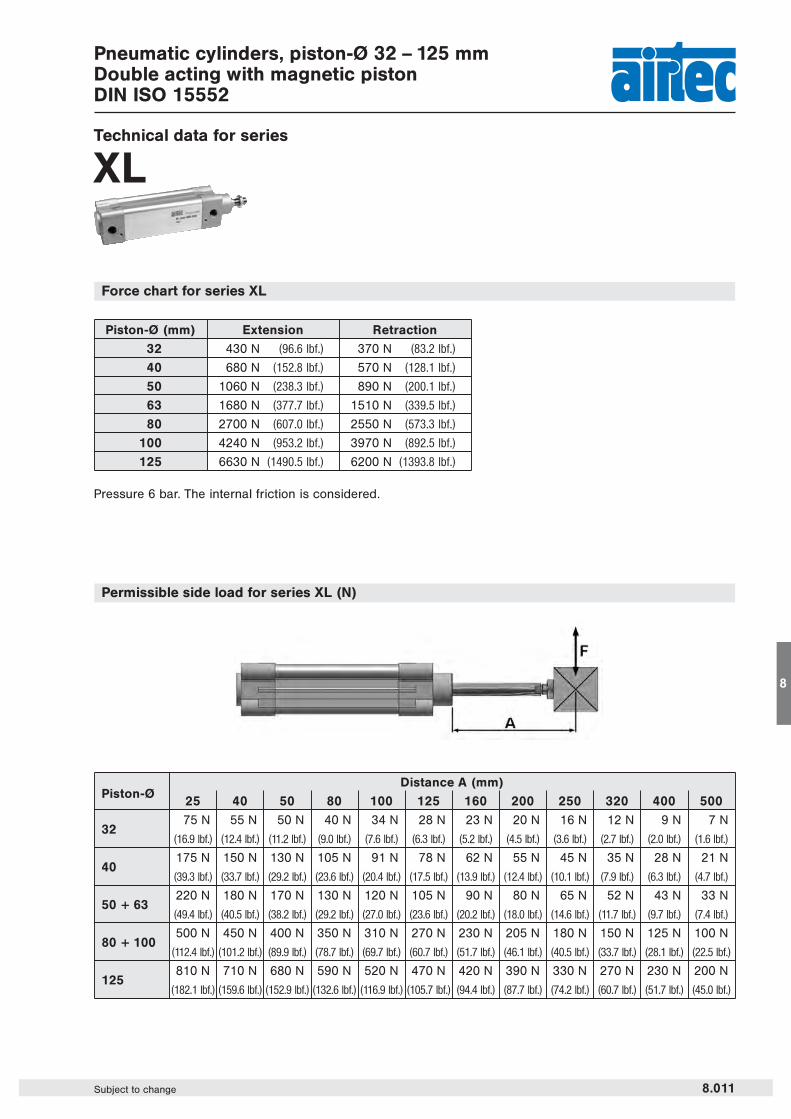
Distance A (mm)Piston-Ø
25 40 50 80 100 125 160 200 250 320 400 500
3275 N 55 N 50 N 40 N 34 N 28 N 23 N 20 N 16 N 12 N 9 N 7 N
(16.9 lbf.) (12.4 lbf.) (11.2 lbf.) (9.0 lbf.) (7.6 lbf.) (6.3 lbf.) (5.2 lbf.) (4.5 lbf.) (3.6 lbf.) (2.7 lbf.) (2.0 lbf.) (1.6 lbf.)
40175 N 150 N 130 N 105 N 91 N 78 N 62 N 55 N 45 N 35 N 28 N 21 N
(39.3 lbf.) (33.7 lbf.) (29.2 lbf.) (23.6 lbf.) (20.4 lbf.) (17.5 lbf.) (13.9 lbf.) (12.4 lbf.) (10.1 lbf.) (7.9 lbf.) (6.3 lbf.) (4.7 lbf.)
50 + 63220 N 180 N 170 N 130 N 120 N 105 N 90 N 80 N 65 N 52 N 43 N 33 N
(49.4 lbf.) (40.5 lbf.) (38.2 lbf.) (29.2 lbf.) (27.0 lbf.) (23.6 lbf.) (20.2 lbf.) (18.0 lbf.) (14.6 lbf.) (11.7 lbf.) (9.7 lbf.) (7.4 lbf.)
80 + 100500 N 450 N 400 N 350 N 310 N 270 N 230 N 205 N 180 N 150 N 125 N 100 N
(112.4 lbf.) (101.2 lbf.) (89.9 lbf.) (78.7 lbf.) (69.7 lbf.) (60.7 lbf.) (51.7 lbf.) (46.1 lbf.) (40.5 lbf.) (33.7 lbf.) (28.1 lbf.) (22.5 lbf.)
125810 N 710 N 680 N 590 N 520 N 470 N 420 N 390 N 330 N 270 N 230 N 200 N
(182.1 lbf.) (159.6 lbf.) (152.9 lbf.) (132.6 lbf.) (116.9 lbf.) (105.7 lbf.) (94.4 lbf.) (87.7 lbf.) (74.2 lbf.) (60.7 lbf.) (51.7 lbf.) (45.0 lbf.)
Piston-Ø (mm) Extension Retraction
32 430 N (96.6 lbf.) 370 N (83.2 lbf.)
40 680 N (152.8 lbf.) 570 N (128.1 lbf.)
50 1060 N (238.3 lbf.) 890 N (200.1 lbf.)
63 1680 N (377.7 lbf.) 1510 N (339.5 lbf.)
80 2700 N (607.0 lbf.) 2550 N (573.3 lbf.)
100 4240 N (953.2 lbf.) 3970 N (892.5 lbf.)
125 6630 N (1490.5 lbf.) 6200 N (1393.8 lbf.)
Pneumatic cylinders, piston-Ø 32 – 125 mmDouble acting with magnetic pistonDIN ISO 15552
Technical data for series
XL
8.011Subject to change
8
Permissible side load for series XL (N)
Force chart for series XL
Pressure 6 bar. The internal friction is considered.

Piston-Ø 32 40 50 63 80 100 125
Mass at 0 mm stroke in kg 0.617 0.925 1.421 1.950 3.250 4.396 6.391(1.360 lbs.) (2.039 lbs.) (3.133 lbs.) (4.299 lbs.) (7.165 lbs.) (9.691 lbs.) (14.089 lbs.)
add-on per 100 mm stroke 0.286 0.403 0.528 0.597 0.861 0.946 1.517(0.630 lb.) (0.888 lb.) (1.164 lbs.) (1.316 lbs.) (1.898 lbs.) (2.085 lbs.) (3.344 lbs.)
Pneumatic cylinders, piston-Ø 32 – 125 mmDouble acting with magnetic pistonDIN ISO 15552
Dimensions for series
XL (Type for order code: –000 and –050)
8.012 Subject to change
An
view A
Piston-A Ø B Ø BA BG Ø D2 E EE J4 KK L2 L3Ø
32 22 30 30 16.5 12 47 G 1/8 6 M 10 x 1.25 18 5
40 24 35 35 16.5 16 54 G 1/4 9 M 12 x 1.25 22 5
50 32 40 40 17.5 20 63 G 1/4 8 M 16 x 1.5 25.5 5
63 32 45 45 17.5 20 74 G 3/8 9.5 M 16 x 1.5 25 5
80 40 45 45 17.5 25 93.5 G 3/8 14 M 20 x 1.5 35 0
100 40 55 55 17.5 25 110 G 1/2 15 M 20 x 1.5 38 0
125 54 60 60 20.5 32 137.5 G 1/2 15 M 27 x 2 46 0d11 d11
Piston-L7 L8 PL RT SW SW1 SW2 TG VA VD WHØ
32 11.5 94 12.5 M6 10 17 6 32.5 4 9.5 26
40 13 105 14 M6 13 19 6 38 4 9.5 30
50 12.75 106 14 M8 17 24 8 46.5 4 9.5 37
63 14.5 121 16.5 M8 17 24 8 56.5 4 9.5 37
80 13.75 128 17 M10 22 30 6 72 4 10 46
100 15.5 138 18 M10 22 30 6 89 4 10 51
125 20 160 18 M12 27 41 8 110 6 11 65

Pneumatic cylinders, piston-Ø 32 – 125 mmDouble acting with magnetic pistonDIN ISO 15552
8.013Subject to change
8
Piston-Ø 32 40 50 63 80 100 125
Mass at 0 mm stroke in kg 0.702 1.065 1.713 2.208 3.780 5.057 9.387(1.548 lbs.) (2.348 lbs.) (3.776 lbs.) (4.868 lbs.) (8.333 lbs.) (11.149 lbs.) (20.694 lbs.)
add-on per 100 mm stroke 0.374 0.559 0.768 0.837 1.243 1.328 2.143(0.824 lb.) (1.232 lbs.) (1.693 lbs.) (1.845 lbs.) (2.740 lbs.) (2.928 lbs.) (4.724 lbs.)
Dimensions for series
XL (Type for order code: –400 and –450)
An
view A
Piston-L7 L8 PL RT SW SW1 SW2 TG VD WH ZMØ
32 11.5 94 12.5 M6 10 17 6 32.5 9.5 26 146
40 13 105 14 M6 13 19 6 38 9.5 30 165
50 12.75 106 14 M8 17 24 8 46.5 9.5 37 180
63 14.5 121 16.5 M8 17 24 8 56.5 9.5 37 195
80 13.75 128 17 M10 22 30 6 72 10 46 220
100 15.5 138 18 M10 22 30 6 89 10 51 240
125 20 160 18 M12 27 41 8 110 10 65 290
Kolben-A Ø B BG Ø D2 E EE J4 KK L2 L3Ø
32 22 30 16.5 12 47 G 1/8 6 M 10 x 1.25 18 5
40 24 35 16.5 16 54 G 1/4 9 M 12 x 1.25 22 5
50 32 40 17.5 20 63 G 1/4 8 M 16 x 1.5 25.5 5
63 32 45 17.5 20 74 G 3/8 9.5 M 16 x 1.5 25 5
80 40 45 17.5 25 93.5 G 3/8 14 M 20 x 1.5 35 0
100 40 55 17.5 25 110 G 1/2 15 M 20 x 1.5 38 0
125 54 60 20.5 32 137.5 G 1/2 15 M 27 x 2 46 0-2 d11 f 7

Pneumatic cylinders, piston-Ø 32 – 63 mmwith twin piston rod (non-rotating)
8.014 Subject to change
Dimensions for series
Piston-Ø 32 40 50 63
Mass at 0 mm stroke in kg 0.744 (1.640 lbs.) 1.121 (2.471 lbs.) 1.641 (3.618 lbs.) 2.678 (5.904 lbs.)
add-on per 100 mm stroke 0.277 (0.610 lb.) 0.370 (0.815 lb.) 0.464 (1.023 lbs.) 0.669 (1.475 lbs.)
view A
XL (Type for order code: –070)
Piston-Ø Ø A Ø B C D5 D7 E EE F Ø G I2 KK
32 8 30 35 32.5 M6 46.5 G 1/8 12 32 19 M6
40 10 35 45 38 M6 53 G 1/4 17 40 22.5 M8
50 12 40 55 46.5 M8 65 G 1/4 14 50 30 M8
63 16 45 65 56.5 M8 75 G 3/8 14 63 38 M10
An
Piston-Ø L1 L2 L3 L4 L5 L6 L7 L8 SW 1 SW 2 SW 3
32 4 15 28.8 4 100 128 76 16 3 6 3
40 4 15 33 4 114 142 88 16 3 6 3
50 5 18 33.8 4 116 151 88 21.5 3 8 4
63 5 22 35 4 124 161 96 21.5 3 8 5
Materials: Piston rod for Ø 32 and 40 mm = stainless steelPiston rod for Ø 50 and 63 mm = steel (chromium plated)
Accessories for pneumatic cylindersseries XLDIN ISO 15552
8.015Subject to change
8
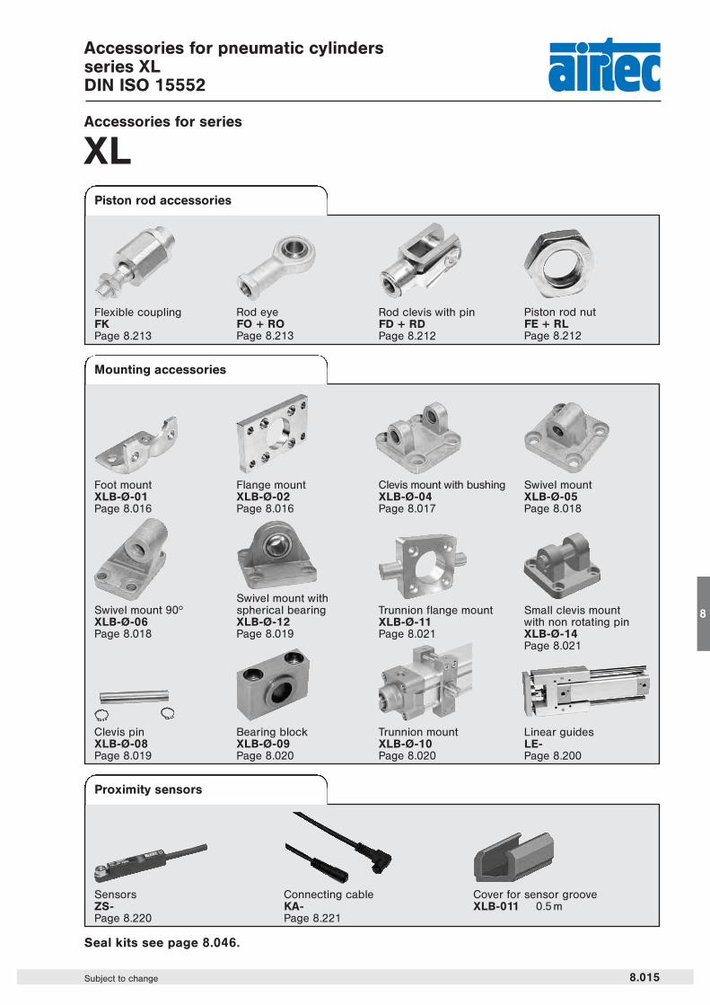
Rod clevis with pinFD + RDPage 8.212
Accessories for series
XLPiston rod accessories
Proximity sensors
Mounting accessories
Flexible couplingFKPage 8.213
Foot mountXLB-Ø-01Page 8.016
Flange mountXLB-Ø-02Page 8.016
Clevis mount with bushingXLB-Ø-04Page 8.017
Swivel mountXLB-Ø-05Page 8.018
Trunnion mountXLB-Ø-10Page 8.020
Bearing blockXLB-Ø-09Page 8.020
Clevis pinXLB-Ø-08Page 8.019
Swivel mount withspherical bearingXLB-Ø-12Page 8.019
Swivel mount 90hXLB-Ø-06Page 8.018
SensorsZS-Page 8.220
Connecting cableKA-Page 8.221
Cover for sensor grooveXLB-011 0.5 m
Rod eyeFO + ROPage 8.213
Piston rod nutFE + RLPage 8.212
Linear guidesLE-Page 8.200
Seal kits see page 8.046.
Trunnion flange mountXLB-Ø-11Page 8.021
Small clevis mount with non rotating pinXLB-Ø-14Page 8.021

Accessories for cylindersseries XL
8.016 Subject to change
Mounting accessories for series
XLFoot mount1 pair
Order number Ø D E Ø FB L4 MF R S TF TG UF
XLB-032-02 30 45 7 5 10 32 M 6 x 20 64 32.5 80
XLB-040-02 35 52 9 5 10 36 M 6 x 20 72 38 90
XLB-050-02 40 65 9 6.5 12 45 M 8 x 20 90 46.5 110
XLB-063-02 45 75 9 6.5 12 50 M 8 x 20 100 56.5 120
XLB-080-02 45 95 12 9 16 63 M 10 x 25 126 72 150
XLB-100-02 55 115 14 9 16 75 M 10 x 25 150 89 170
XLB-125-02 60 140 16 10.5 20 90 M 12 x 25 180 110* 205
H11 H13 – 0.5 JS14 JS14 JS14 ± 0.2* ± 0.3
Order number Ø AB AH AO AU AT E L7 R2 S TG TG2 TR
XLB-032-01 7 32 11 24 4 45 30 15 M 6 x 20 32.5 16.25 32
XLB-040-01 10 36 8 28 4 52 30 17.5 M 6 x 20 38 19 36
XLB-050-01 10 45 15 32 5 65 36 20 M 8 x 20 46.5 23.25 45
XLB-063-01 10 50 13 32 5 75 35 22.5 M 8 x 20 56.5 28.25 50
XLB-080-01 12 63 14 41 6 95 47 22.5 M 10 x 20 72 36 63
XLB-100-01 14.5 71 16 41 6 115 53 27.5 M 10 x 20 89 44.5 75
XLB-125-01 16.5 90 25 45 8 140 70 30 M 12 x 25 110* 55 90
H14 JS16 ± 0.2 H15 ± 0.2* ± 0.3 JS14
Material: steel (zinc-plated)
Material: steel (zinc-plated)
Flange mount
DIN 7984
DIN EN ISO4762
Accessories for cylindersseries XL
8.017Subject to change
8
Mounting accessories for series
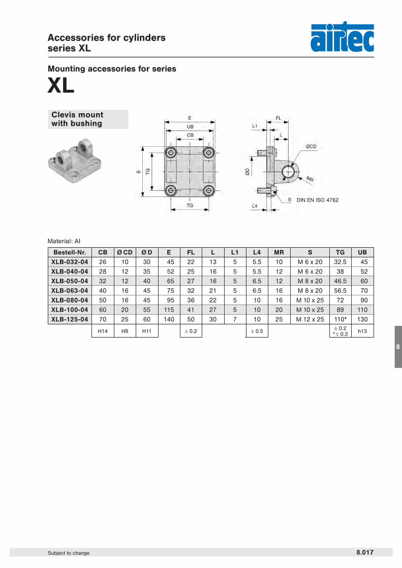
XLClevis mountwith bushing
Material: Al
Bestell-Nr. CB Ø CD Ø D E FL L L1 L4 MR S TG UB
XLB-032-04 26 10 30 45 22 13 5 5.5 10 M 6 x 20 32.5 45
XLB-040-04 28 12 35 52 25 16 5 5.5 12 M 6 x 20 38 52
XLB-050-04 32 12 40 65 27 16 5 6.5 12 M 8 x 20 46.5 60
XLB-063-04 40 16 45 75 32 21 5 6.5 16 M 8 x 20 56.5 70
XLB-080-04 50 16 45 95 36 22 5 10 16 M 10 x 25 72 90
XLB-100-04 60 20 55 115 41 27 5 10 20 M 10 x 25 89 110
XLB-125-04 70 25 60 140 50 30 7 10 25 M 12 x 25 110* 130
H14 H9 H11 ± 0.2 ± 0.5 ± 0.2* ± 0.3 h13
DIN EN ISO 4762

Accessories for cylindersseries XL
8.018 Subject to change
Mounting accessories for series
XL
Order number BR BT Ø CK Ø D EA EM GL Ø HB L2 LD PH RA TE UL UR
XLB-032-06 10 8 10 21 10 26 21 6.6 1.6 3 32 18 38 51 31
XLB-040-06 11 10 12 21 15 28 24 6.6 1.6 3 36 22 41 54 35
XLB-050-06 13 12 12 21 16 32 33 9 1.6 3 45 30 50 65 45
XLB-063-06 15 14 16 21 16 40 37 9 1.6 3 50 35 52 67 50
XLB-080-06 15 14 16 21 20 50 47 11 2.5 3 63 40 66 86 60
XLB-100-06 19 17 20 11 20 60 55 11 2.5 3 71 50 76 96 70
XLB-125-06 22.5 20 25 21 30 70 70 14 3.2 3 90 60 94 124 90H9 JS14 H13 JS15 JS14 JS14
Order number Ø CD Ø D E EW FL L L1 L4 MR S TG
XLB-032-05 10 30 45 26 22 13 5 5.5 10 M 6 x 20 32.5
XLB-040-05 12 35 52 28 25 16 5 5.5 12 M 6 x 20 38
XLB-050-05 12 40 65 32 27 16 5 6.5 12 M 8 x 20 46.5
XLB-063-05 16 45 75 40 32 21 5 6.5 16 M 8 x 20 56.5
XLB-080-05 16 45 95 50 36 22 5 10 16 M 10 x 25 72
XLB-100-05 20 55 115 60 41 27 5 10 20 M 10 x 25 89
XLB-125-05 25 60 140 70 50 30 7 10 25 M 12 x 25 110*
H9 H11 ± 0.2 ± 0.5 ± 0.2* ± 0.3
Swivel mount
Material: Al
Swivel mount 90°
Material: Al
DIN EN ISO 4762
Accessories for cylindersseries XL
8.019Subject to change
8
Mounting accessories for series
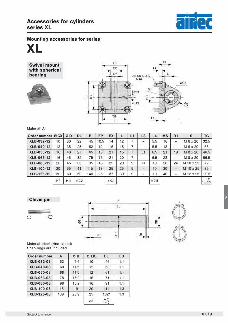
XLSwivel mountwith sphericalbearing
Order number A Ø B Ø EK EL LB
XLB-032-08 53 9.6 10 46 1.1
XLB-040-08 60 11.5 12 53 1.1
XLB-050-08 68 11.5 12 61 1.1
XLB-063-08 78 15.2 16 71 1.1
XLB-080-08 98 15.2 16 91 1.1
XLB-100-08 118 19 20 111 1.3
XLB-125-08 139 23.9 25 132* 1.3
e 8 + 2* + 3
Order number Ø CX Ø D DL E EP EX L L1 L3 L4 MS R1 S TG
XLB-032-12 10 30 22 45 10.5 14 12 7 – 5.5 16 – M 6 x 20 32.5
XLB-040-12 12 35 25 52 12 16 15 7 – 5.5 18 – M 6 x 20 38
XLB-050-12 16 40 27 65 15 21 15 7 51 6.5 21 19 M 8 x 20 46.5
XLB-063-12 16 45 32 75 15 21 20 7 – 6.5 23 – M 8 x 20 56.5
XLB-080-12 20 45 36 95 18 25 20 9 74 10 28 24 M 10 x 25 72
XLB-100-12 20 55 41 115 18 25 25 9 – 10 30 – M 10 x 25 89
XLB-125-12 30 60 50 140 25 37 30 9 – 10 40 – M 12 x 25 110*
H7 H11 ± 0.2 ± 0.1 ± 0.5 ± 0.2* ± 0.3
Material: Al
Clevis pin
Material: steel (zinc-plated)Snap rings are included.
Mounting accessories for series
XL
Accessories for cylindersseries XL
8.020 Subject to change
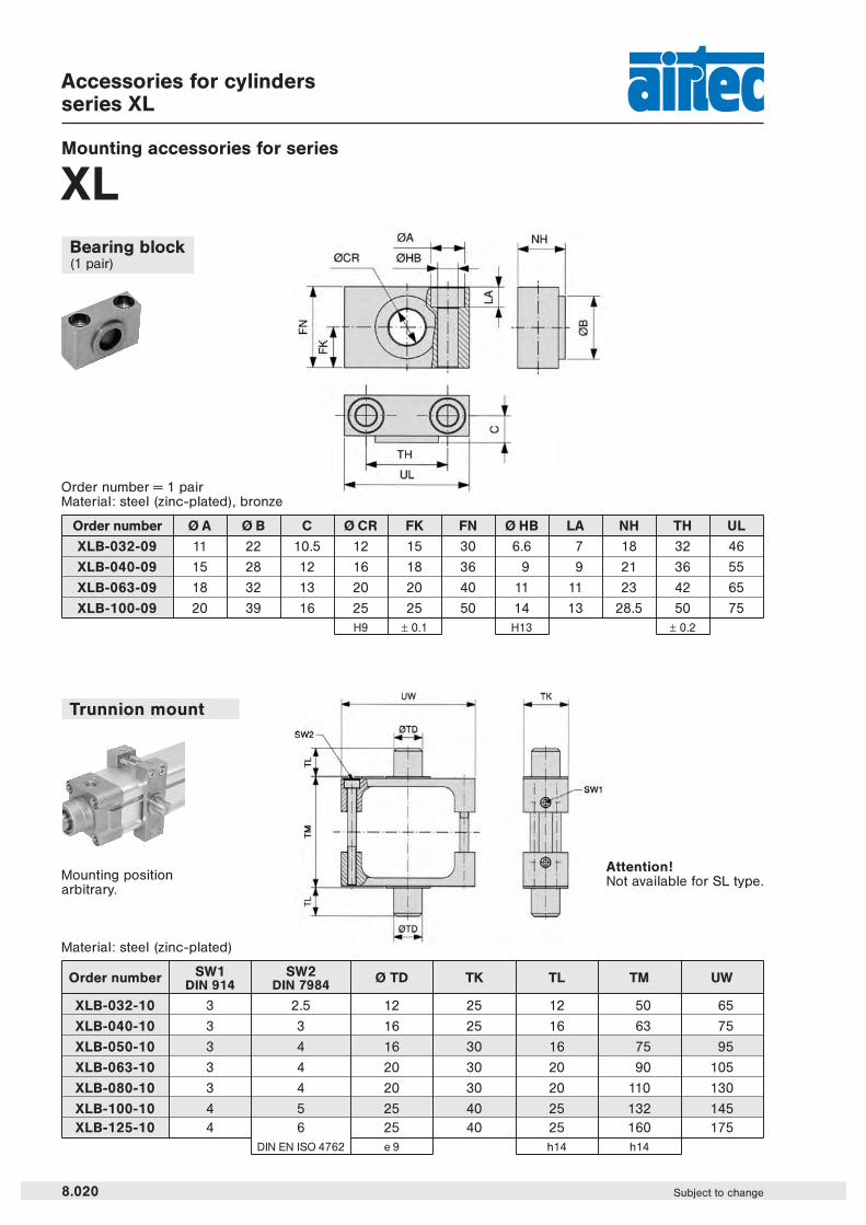
Bearing block(1 pair)
Order number Ø A Ø B C Ø CR FK FN Ø HB LA NH TH UL
XLB-032-09 11 22 10.5 12 15 30 6.6 7 18 32 46
XLB-040-09 15 28 12 16 18 36 9 9 21 36 55
XLB-063-09 18 32 13 20 20 40 11 11 23 42 65
XLB-100-09 20 39 16 25 25 50 14 13 28.5 50 75H9 ± 0.1 H13 ± 0.2
Order number SW1 SW2 Ø TD TK TL TM UWDIN 914 DIN 7984
XLB-032-10 3 2.5 12 25 12 50 65
XLB-040-10 3 3 16 25 16 63 75
XLB-050-10 3 4 16 30 16 75 95
XLB-063-10 3 4 20 30 20 90 105
XLB-080-10 3 4 20 30 20 110 130
XLB-100-10 4 5 25 40 25 132 145XLB-125-10 4 6 25 40 25 160 175
DIN EN ISO 4762 e 9 h14 h14
Trunnion mount
Material: steel (zinc-plated)
Material: steel (zinc-plated), bronzeOrder number = 1 pair
Mounting positionarbitrary.
Attention!Not available for SL type.

Accessories for cylindersseries XL
Mounting accessories for series
XL
8.021Subject to change
8
Trunnion flange mount
Material of clevis: Alof pin: steel (zinc-plated)
Order number CF CG CP D E FM L1 L4 L10 R4 S SR TG
XLB-032-14 10 14 34 30 45 22 5 5.5 9 17 M 6 x 20 10 32.5
XLB-040-14 12 16 40 35 52 25 5 5.5 9 20 M 6 x 20 12 38
XLB-050-14 16 21 45 40 65 27 5 6.5 11 22 M 8 x 20 14 46.5
XLB-063-14 16 21 51 45 75 32 5 6.5 11 25 M 8 x 20 18 56.5
XLB-080-14 20 25 65 45 95 36 5 10 14 30 M 10 x 25 20 72
XLB-100-14 20 25 75 55 115 41 5 10 14 32 M 10 x 25 22 89
XLB-125-14 30 37 97 60 140 50 7 10 20 42 M 12 x 25 25 110*
F7 D10 d 12 H11 ± 0.2 ± 0.5 ± 0.2* ± 0.3
Order number D L L4 S TD TG TK TL Ø TM US
XLB-032-11 30 6.5 8 M 6 x 20 12 32.5 14 12 50 46
XLB-040-11 35 9 13 M 6 x 25 16 38 19 16 63 59
XLB-050-11 40 9 11 M 8 x 25 16 46.5 19 16 75 69
XLB-063-11 45 11.5 16 M 8 x 30 20 56.5 24 20 90 84
XLB-080-11 45 11.5 14 M 10 x 30 20 72 24 20 110 102
XLB-100-11 55 14 19 M 10 x 35 25 89 29 25 132 125H11 + 0.2 e9 ± 0.2 h14 h14
Material: steel (zinc-plated)
Small clevis mount with non rotating pin

Order number Ø
VS-XL-032-01 32 mm
VS-XL-040-01 40 mm
VS-XL-050-01 50 mm
VS-XL-063-01 63 mm
VS-XL-080-01 80 mm
VS-XL-100-01 100 mm
VS-XL-125-01 125 mm
Order number Ø
VS-XL-032-02 32 mm
VS-XL-040-02 40 mm
VS-XL-050-02 50 mm
VS-XL-063-02 63 mm
VS-XL-080-02 80 mm
VS-XL-100-02 100 mm
VS-XL-125-02 125 mm
Pos. Part Quantity
1 Wiper and seal element 1
2 Cushion seal 2
3 O-ring 2
4 Piston 1
Grease 1
Seal kitsfor series XL and XLVK
8.046 Subject to change
For cylinders with piston rod on one side
Seal kits – standard
Seal kits – Viton
Content

Order number Ø
VS-XL-032-03 32 mm
VS-XL-040-03 40 mm
VS-XL-050-03 50 mm
VS-XL-063-03 63 mm
VS-XL-080-03 80 mm
VS-XL-100-03 100 mm
VS-XL-125-03 125 mm
Order number Ø
VS-XL-032-04 32 mm
VS-XL-040-04 40 mm
VS-XL-050-04 50 mm
VS-XL-063-04 63 mm
VS-XL-080-04 80 mm
VS-XL-100-04 100 mm
VS-XL-125-04 125 mm
Seal kitsfor series XL and XLVK
8.047Subject to change
Pos. Part Quantity
1 Wiper and seal element 2
2 Cushion seal 2
3 O-ring 2
4 Piston 1
Grease 1
For cylinders with piston rod on both sides
Seal kits – standard
Seal kits – Viton
Content
8

OverviewPiston rod accessories
8.211Subject to change
8
Series Cylinder Ø Piston rod Rod clevis Piston rod Flexible Rod eyemm thread nut coupling
HM Ø 8 and 10 M 4 RD-10 RL-10 – –
NXD Ø 12
HM Ø 12 and 16 M 6 RD-16 RL-16 FK-16 RO-16
NXD Ø 16
HM Ø 20 M 8 RD-20 RL-20 FK-20 RO-20
XV Ø 20 and 25
NXD Ø 20 to 40
HM Ø 25M 10 x 1.25 RD-25 RL-25 FK-32 RO-25
XL Ø 32
XV Ø 32 and 40
HM Ø 32 M 10 RD-32 RL-32 FK-33 RO-32
HM Ø 40 M 12 RD-40 RL-40 FK-41 RO-40
HM Ø 50 and 63 M 16 RD-63 RL-50/63 – RO-50
NXD Ø 50 and 63 M 12 x 1.25 FD-40 FE-40 FK-40 FO-40XL Ø 40
XV Ø 50 and 63
NXD Ø 80 M 16 x 1.5 FD-63 FE-63 FK-63 FO-63XL Ø 50 and 63
NXD Ø 100
XL Ø 80 and 100 M 20 x 1.5 FD-80 FE-80 FK-80 FO-80
XV Ø 80 and 100
XL Ø 125 M 27 x 2 FD-125 FE-125 FK-125 FO-125
XG Ø 160 and 200 M 36 x 2 FD-200 FE-200 FK-200 FO-160/200
XG Ø 250 M 42 x 2 FD-250 FE-250 – –
XG Ø 320 M 48 x 2 FD-320 FE-320 – –
Assignment to series

Piston rod accessories
Rod clevis with pin
Material: steel (zinc-plated)
Piston rod nut
8.212 Subject to change
Material: steel (zinc-plated)spring steel
Rod clevis FD-125 and FD-200, pin with snap rings.
Order number A B C D E F G H
RD-10 M 4 8 16 11.5 4 21 8 4
RD-16 M 6 12 24 16 6 31 12 6
RD-20 M 8 16 32 22 8 42 16 8
RD-25 M 10 x 1.25 20 40 26 10 52 20 10
RD-32 M 10 20 40 26 10 52 20 10
RD-40 M 12 24 48 32 12 62 24 12
RD-63 M 16 32 64 36 16 83 32 16
FD-40 M 12 x 1.25 24 48 32 12 62 24 12
FD-63 M 16 x 1.5 32 64 40 16 83 32 16
FD-80 M 20 x 1.5 40 80 50 20 105 40 20
FD-125 M 27 x 2 54 110 65 30 148 55 30
FD-200 M 36 x 2 72 144 84 35 188 70 35
FD-250 M 42 x 2 84 168 104.5 40 232 85 40
FD-320 M 48 x 2 96 192 117.5 50 265 96 50
Order number A B C
RL-10 M 4 3.2 7
RL-16 M 6 5 10
RL-20 M 8 6.5 13
RL-25 M 10 x 1.25 6 17
RL-32 M 10 6 17
RL-40 M 12 7 19
RL-50/63 M 16 8 24
FE-40 M 12 x 1.25 7 19
FE-63 M 16 x 1.5 8 24
FE-80 M 20 x 1.5 9 30
FE-125 M 27 x 2 12 41
FE-200 M 36 x 2 14 55
FE-250 M 42 x 2 16 65
FE-320 M 48 x 2 18 75
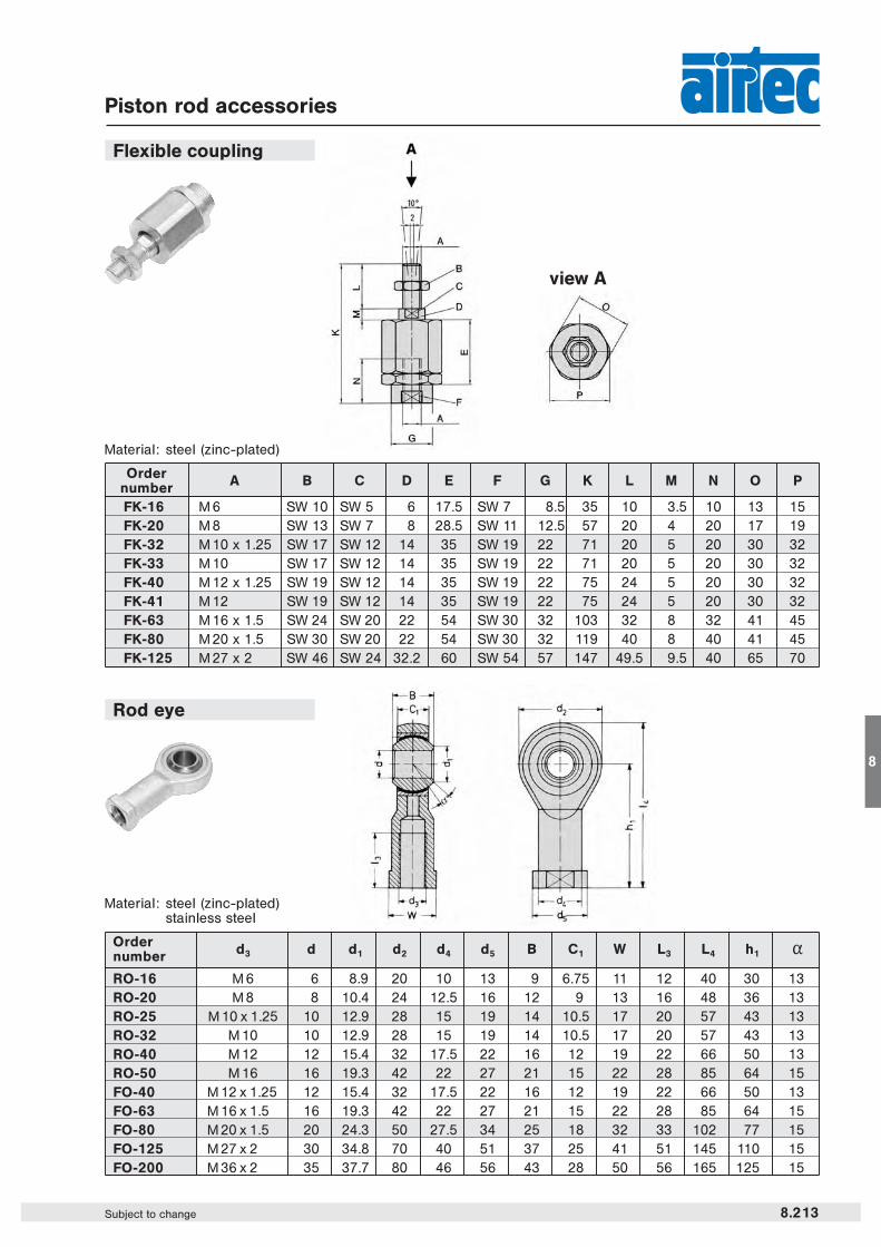
Ordernumber d3 d d1 d2 d4 d5 B C1 W L3 L4 h1 “
RO-16 M 6 6 8.9 20 10 13 9 6.75 11 12 40 30 13RO-20 M 8 8 10.4 24 12.5 16 12 9 13 16 48 36 13RO-25 M 10 x 1.25 10 12.9 28 15 19 14 10.5 17 20 57 43 13RO-32 M 10 10 12.9 28 15 19 14 10.5 17 20 57 43 13RO-40 M 12 12 15.4 32 17.5 22 16 12 19 22 66 50 13RO-50 M 16 16 19.3 42 22 27 21 15 22 28 85 64 15FO-40 M 12 x 1.25 12 15.4 32 17.5 22 16 12 19 22 66 50 13FO-63 M 16 x 1.5 16 19.3 42 22 27 21 15 22 28 85 64 15FO-80 M 20 x 1.5 20 24.3 50 27.5 34 25 18 32 33 102 77 15FO-125 M 27 x 2 30 34.8 70 40 51 37 25 41 51 145 110 15FO-200 M 36 x 2 35 37.7 80 46 56 43 28 50 56 165 125 15
Ordernumber A B C D E F G K L M N O P
FK-16 M 6 SW 10 SW 5 6 17.5 SW 7 8.5 35 10 3.5 10 13 15FK-20 M 8 SW 13 SW 7 8 28.5 SW 11 12.5 57 20 4 20 17 19FK-32 M 10 x 1.25 SW 17 SW 12 14 35 SW 19 22 71 20 5 20 30 32FK-33 M 10 SW 17 SW 12 14 35 SW 19 22 71 20 5 20 30 32FK-40 M 12 x 1.25 SW 19 SW 12 14 35 SW 19 22 75 24 5 20 30 32FK-41 M 12 SW 19 SW 12 14 35 SW 19 22 75 24 5 20 30 32FK-63 M 16 x 1.5 SW 24 SW 20 22 54 SW 30 32 103 32 8 32 41 45FK-80 M 20 x 1.5 SW 30 SW 20 22 54 SW 30 32 119 40 8 40 41 45FK-125 M 27 x 2 SW 46 SW 24 32.2 60 SW 54 57 147 49.5 9.5 40 65 70
Piston rod accessories
Flexible coupling
Rod eye
Material: steel (zinc-plated)stainless steel
Material: steel (zinc-plated)
view A
8.213Subject to change
8

Order number ZS-5600 ZS-5601 ZS-5700 ZS-5700-10 ZS-5701Design 2-pole Reed sensor 3-pole Reed sensor*
(non-polarized) normally open normally openCable l 2.8, PURCable cross section n/aCable length 3 m 0,3 m 5 m 10 m 0,3 mCable plug – M 8 – – M 8Overtravel speed n/aMax. absolute hysteresis n/aTemperature drift n/aMin. absolute repeat accuracy n/aOperating temperature – 10 °C … + 70 °CDegree of protection IP 68Housing material PlasticSwitching status indication LED red LED yellowRated operational voltage 5 … 240 V AC/DC / 5 … 60 V AC/DC 5 … 30 V DCRated operational DC ≤ 100 mA ≤ 500 mAcurrent IE AC ≤ 100 mA ≤ 500 mABreaking capacity ≤ 10 WNo-load current n/a ≤ 10 mAMax. OFF-state current 0 mAMax. switching frequency ≤ 0.2 kHzRated insulation voltage n/aShort-circuit protection noMax. voltage drop at IE ≤ 2.5 V ≤ 0.1 VWire breakage noReverse polarity protection yesVibration resistance 9 g (1,5 mm, 10 – 55 Hz – 10 Hz)Shock resistance 30 g (11 ms)Explosion proof –
Proximity sensors
8.220 Subject to change
ZS-5600 ZS-5601
Function principlesMagnetic field sensors are actuated by magnetic fields and are especially suited for piston position detection inpneumatic cylinders. Based on the fact that magnetic fields can permeate non-magnetizable metals, it is possibleto detect a permanent magnet attached to the piston through the aluminum wall of the cylinder.
Mounting tipThe sensor is firmly fixed in the groove by clockwise rotation of the screw.
* Useable as 2-wire contact, voltage 0 … 30 V AC / 0 … 30 V DC, LED has no function.
ZS-5700, ZS-5700-10 ZS-5701
ZS-6700, ZS-7300 ZS-6701, ZS-7301
DimensionsWiring diagram
ZS-5600, ZS-6700, ZS-7300; A = 3.000 ± 20
ZS-5700-10; A = 10.000 ± 20
ZS-5700, ZS-7300; A = 5.000 ± 20
ZS-5601, ZS-5701, ZS-6701, ZS-7301
Dimensions
1
4
3
Proximity sensors Reed contact

Order number ZS-6700 ZS-6701 ZS-7300 ZS-7301Design electronic, magnet-induktive sensor,
normally open PNP outputCable l 2.8, PUR l 3, LifYY-11Y, PURCable cross section n/a 3 x 0.14 mm2
Cable lengths 3 m 0.3 m 3 m 0.3 mCable plug – M 8 – M 8Overtravel speed n/a ≤ 10 m/sMax. absolute hysteresis n/a ≤ 1 mmTemperature drift n/a ≤ 0.1 mmMin. absolute repeat accuracy n/a ≤ ± 0.1 mmOperating temperature – 10 °C … + 70 °C – 25 °C … + 70 °CDegree of protection IP 68 IP 67Housing material Plastic Plastic, PA 12Switching status indication LED green LED yellowRated operational voltage 5 … 30 V DC 10 … 30 V DC, max. ripple ≤ 10 % Upp
Rated operational DC ≤ 200 mA ≤ 200 mAcurrent IE AC – –Breaking capacity 6 W 6 WNo-load current ≤ 10 mA ≤ 15 mAMax. OFF-state current n/a ≤ 0.1 mAMax. switching frequency ≤ 1 kHz ≤ 1 kHzRated insulation voltage n/a ≤ 0.5 kVShort-circuit protection yes yes, cyclicMax. voltage drop at IE ≤ 1.0 V ≤ 1.8 VWire breakage yes yesReverse polarity protection yes yes /completeVibration resistance 9 g (1.5 mm, 10 – 55 Hz – 10 Hz) 55 Hz (1 mm)Shock resistance 50 g (11 ms) 30 g (11 ms)Explosion proof – II 3 GD EEx nA II T4 X IP 67 T 110 °C
Proximity sensors
8.221Subject to change
8
Order number Length of cable Connection
KA-30 3 m 8 mm sensor snap-in, straight
KA-50 5 m 8 mm sensor snap-in, straight
KA-51 5 m 8 mm sensor snap-in, 90°
KA-100 10 m 8 mm sensor snap-in, straight
KA-101 10 m 8 mm sensor snap-in, 90°
Mounting bracket for round cylinder Ø 8 – 63 mm
Connecting cable for ZS-5601, ZS-5701, ZS-6701 and ZS-7301
BU 3
4 BK
1 BN
Proximity sensors electronic
Cable: PUR, black, 3 x 0.25 mm2, l 3.9, high flexibleOperating voltage 0 … 48 V AC/ DC
Order number Piston-Ø
NT-250 8 – 25 mm
NT-500 32 – 63 mm
Material: metal, plastic PA GI/6T
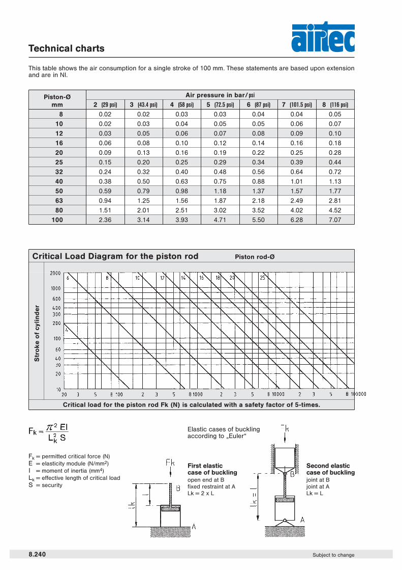
Technical charts
8.240 Subject to change
Piston-Ø Air pressure in bar/ psi
mm 2 (29 psi) 3 (43.4 psi) 4 (58 psi) 5 (72.5 psi) 6 (87 psi) 7 (101.5 psi) 8 (116 psi)
8 0.02 0.02 0.03 0.03 0.04 0.04 0.05
10 0.02 0.03 0.04 0.05 0.05 0.06 0.07
12 0.03 0.05 0.06 0.07 0.08 0.09 0.10
16 0.06 0.08 0.10 0.12 0.14 0.16 0.18
20 0.09 0.13 0.16 0.19 0.22 0.25 0.28
25 0.15 0.20 0.25 0.29 0.34 0.39 0.44
32 0.24 0.32 0.40 0.48 0.56 0.64 0.72
40 0.38 0.50 0.63 0.75 0.88 1.01 1.13
50 0.59 0.79 0.98 1.18 1.37 1.57 1.77
63 0.94 1.25 1.56 1.87 2.18 2.49 2.81
80 1.51 2.01 2.51 3.02 3.52 4.02 4.52
100 2.36 3.14 3.93 4.71 5.50 6.28 7.07
Critical Load Diagram for the piston rod Piston rod-Ø
This table shows the air consumption for a single stroke of 100 mm. These statements are based upon extensionand are in Nl.
Elastic cases of bucklingaccording to „Euler“
First elasticcase of bucklingopen end at Bfixed restraint at ALk = 2 x L
Second elasticcase of bucklingjoint at Bjoint at ALk = L
Critical load for the piston rod Fk (N) is calculated with a safety factor of 5-times.
Fk = permitted critical force (N)E = elasticity module (N/mm2)l = moment of inertia (mm4)Lk = effective length of critical loadS = security
Str
ok
e o
f cy
lin
de
r