Embed Size (px)
Citation preview

R
Virtex-5 FXT PowerPC 440 and MicroBlaze [Guide Subtitle] [optional]
UG511 (v1.2.1) July 30, 2009 [optional]
Virtex-5 FXT PowerPC 440 and MicroBlaze Edition Kit Reference SystemsUG511 (v1.2.1) July 30, 2009

Virtex-5 FXT Kit Reference Systems www.xilinx.com UG511 (v1.2.1) July 30, 2009
Xilinx is disclosing this user guide, manual, release note, and/or specification (the "Documentation") to you solely for use in the development of designs to operate with Xilinx hardware devices. You may not reproduce, distribute, republish, download, display, post, or transmit the Documentation in any form or by any means including, but not limited to, electronic, mechanical, photocopying, recording, or otherwise, without the prior written consent of Xilinx. Xilinx expressly disclaims any liability arising out of your use of the Documentation. Xilinx reserves the right, at its sole discretion, to change the Documentation without notice at any time. Xilinx assumes no obligation to correct any errors contained in the Documentation, or to advise you of any corrections or updates. Xilinx expressly disclaims any liability in connection with technical support or assistance that may be provided to you in connection with the Information.
THE DOCUMENTATION IS DISCLOSED TO YOU “AS-IS” WITH NO WARRANTY OF ANY KIND. XILINX MAKES NO OTHER WARRANTIES, WHETHER EXPRESS, IMPLIED, OR STATUTORY, REGARDING THE DOCUMENTATION, INCLUDING ANY WARRANTIES OF MERCHANTABILITY, FITNESS FOR A PARTICULAR PURPOSE, OR NONINFRINGEMENT OF THIRD-PARTY RIGHTS. IN NO EVENT WILL XILINX BE LIABLE FOR ANY CONSEQUENTIAL, INDIRECT, EXEMPLARY, SPECIAL, OR INCIDENTAL DAMAGES, INCLUDING ANY LOSS OF DATA OR LOST PROFITS, ARISING FROM YOUR USE OF THE DOCUMENTATION.
© 2008-2009 Xilinx, Inc. All rights reserved.
XILINX, the Xilinx logo, the Brand Window, and other designated brands included herein are trademarks of Xilinx, Inc. The PowerPC name and logo are registered trademarks of IBM Corp. and are used under license. All other trademarks are the property of their respective owners.
R
UG511 (v1.2.1) July 30, 2009 www.xilinx.com Virtex-5 FXT Kit Reference Systems
Revision HistoryThe following table shows the revision history for this document.
Date Version Revision
7/29/08 1.0 Initial Xilinx release.
12/19/08 1.1Updated to 10.1.3. Added content on Flash file system. Updated steps on programming parallel Flash. Added chapter on software application to read, write, and erase Flash.
1/26/09 1.1.1 Updated reference system links.
5/21/09 1.2Updated to 11.1. Added steps for applying the xlltemac patch. Updated section on the MLD file set to use the 11.1 file set included in the project.
7/30/09 1.2.1 Updated ref system CID numbers; updated to current date.

Virtex-5 FXT Kit Reference Systems www.xilinx.com UG511 (v1.2.1) July 30, 2009

Virtex-5 FXT Kit Reference Systems www.xilinx.com 5UG511 (v1.2.1) July 30, 2009
Preface: About This GuideGuide Contents . . . . . . . . . . . . . . . . . . . . . . . . . . . . . . . . . . . . . . . . . . . . . . . . . . . . . . . . . . . . . . 7Hardware and Software Requirements . . . . . . . . . . . . . . . . . . . . . . . . . . . . . . . . . . . . . . . 7References . . . . . . . . . . . . . . . . . . . . . . . . . . . . . . . . . . . . . . . . . . . . . . . . . . . . . . . . . . . . . . . . . . . 8Additional Resources . . . . . . . . . . . . . . . . . . . . . . . . . . . . . . . . . . . . . . . . . . . . . . . . . . . . . . . . 8Conventions . . . . . . . . . . . . . . . . . . . . . . . . . . . . . . . . . . . . . . . . . . . . . . . . . . . . . . . . . . . . . . . . . 8
Typographical . . . . . . . . . . . . . . . . . . . . . . . . . . . . . . . . . . . . . . . . . . . . . . . . . . . . . . . . . . . . . 8Online Document . . . . . . . . . . . . . . . . . . . . . . . . . . . . . . . . . . . . . . . . . . . . . . . . . . . . . . . . . . 9
Chapter 1: Hardware PlatformIntroduction . . . . . . . . . . . . . . . . . . . . . . . . . . . . . . . . . . . . . . . . . . . . . . . . . . . . . . . . . . . . . . . . 11PowerPC 440 Processor Reference System . . . . . . . . . . . . . . . . . . . . . . . . . . . . . . . . . . . 11
Block Diagram . . . . . . . . . . . . . . . . . . . . . . . . . . . . . . . . . . . . . . . . . . . . . . . . . . . . . . . . . . . 11Address Map . . . . . . . . . . . . . . . . . . . . . . . . . . . . . . . . . . . . . . . . . . . . . . . . . . . . . . . . . . . . 12System Configuration . . . . . . . . . . . . . . . . . . . . . . . . . . . . . . . . . . . . . . . . . . . . . . . . . . . . . 12
MicroBlaze Processor Reference System . . . . . . . . . . . . . . . . . . . . . . . . . . . . . . . . . . . . . 13Block Diagram . . . . . . . . . . . . . . . . . . . . . . . . . . . . . . . . . . . . . . . . . . . . . . . . . . . . . . . . . . . 13Address Map . . . . . . . . . . . . . . . . . . . . . . . . . . . . . . . . . . . . . . . . . . . . . . . . . . . . . . . . . . . . 13System Configuration . . . . . . . . . . . . . . . . . . . . . . . . . . . . . . . . . . . . . . . . . . . . . . . . . . . . . 14
Chapter 2: HelloWorld Software ApplicationIntroduction . . . . . . . . . . . . . . . . . . . . . . . . . . . . . . . . . . . . . . . . . . . . . . . . . . . . . . . . . . . . . . . . 15Executing the HelloWorld Software Application . . . . . . . . . . . . . . . . . . . . . . . . . . . . . 15
Executing the HelloWorld Application Using the Pre-Built Bitstream . . . . . . . . . . . . 15Executing the HelloWorld Software Application from XPS . . . . . . . . . . . . . . . . . . . . . 18
Commands in the HelloWorld Software Application. . . . . . . . . . . . . . . . . . . . . . . . . 19Booting the HelloWorld Application from Serial Flash. . . . . . . . . . . . . . . . . . . . . . . 20
Chapter 3: LynuxWorks BlueCat LinuxIntroduction . . . . . . . . . . . . . . . . . . . . . . . . . . . . . . . . . . . . . . . . . . . . . . . . . . . . . . . . . . . . . . . . 23Executing the BlueCat Linux Images . . . . . . . . . . . . . . . . . . . . . . . . . . . . . . . . . . . . . . . . . 23
Executing the BlueCat Linux Image with a Ramdisk File System . . . . . . . . . . . . . . . . 23Executing the BlueCat Linux Image Using the Pre-Built Bitstream . . . . . . . . . . . . . . . . 24Executing the BlueCat Linux Image from XPS . . . . . . . . . . . . . . . . . . . . . . . . . . . . . . . . 26
Executing the BlueCat Linux Image with a JFFS2 File System . . . . . . . . . . . . . . . . . . . 26Executing the BlueCat Linux Image Using the Pre-Built Bitstream . . . . . . . . . . . . . . . . 27Executing the BlueCat Linux Image from XPS . . . . . . . . . . . . . . . . . . . . . . . . . . . . . . . . 32
Executing BlueCat Linux Commands . . . . . . . . . . . . . . . . . . . . . . . . . . . . . . . . . . . . . . . . 35Web Server Demonstration . . . . . . . . . . . . . . . . . . . . . . . . . . . . . . . . . . . . . . . . . . . . . . . . . . 36Building the BlueCat Linux Kernel Image . . . . . . . . . . . . . . . . . . . . . . . . . . . . . . . . . . . 37
Installing the BlueCat Linux Distribution . . . . . . . . . . . . . . . . . . . . . . . . . . . . . . . . . . . . 37Using the Provided Demo Directories . . . . . . . . . . . . . . . . . . . . . . . . . . . . . . . . . . . . . . . 37
Table of Contents

6 www.xilinx.com Virtex-5 FXT Kit Reference SystemsUG511 (v1.2.1) July 30, 2009
R
Getting the MLD File Set . . . . . . . . . . . . . . . . . . . . . . . . . . . . . . . . . . . . . . . . . . . . . . . . . . . 38Generating the BSP . . . . . . . . . . . . . . . . . . . . . . . . . . . . . . . . . . . . . . . . . . . . . . . . . . . . . . . 38Rebuilding the Kernel Image . . . . . . . . . . . . . . . . . . . . . . . . . . . . . . . . . . . . . . . . . . . . . . . 39
Booting the BlueCat Linux Image from Parallel Flash . . . . . . . . . . . . . . . . . . . . . . . . 41Programming the Flash with the Provided Files . . . . . . . . . . . . . . . . . . . . . . . . . . . . . . . 41
Programming the KDI File . . . . . . . . . . . . . . . . . . . . . . . . . . . . . . . . . . . . . . . . . . . . . . . 41Programming the BIN File . . . . . . . . . . . . . . . . . . . . . . . . . . . . . . . . . . . . . . . . . . . . . . . 43Programming the Root File System . . . . . . . . . . . . . . . . . . . . . . . . . . . . . . . . . . . . . . . . 44Running the Design . . . . . . . . . . . . . . . . . . . . . . . . . . . . . . . . . . . . . . . . . . . . . . . . . . . . 45
Generating New Flash Files and Programming the Flash . . . . . . . . . . . . . . . . . . . . . . . 46Programming the KDI File and Creating the Bootloader . . . . . . . . . . . . . . . . . . . . . . . . 46Creating and Programming the BIN File . . . . . . . . . . . . . . . . . . . . . . . . . . . . . . . . . . . . 49Programming the Root File System . . . . . . . . . . . . . . . . . . . . . . . . . . . . . . . . . . . . . . . . 50Running the Design . . . . . . . . . . . . . . . . . . . . . . . . . . . . . . . . . . . . . . . . . . . . . . . . . . . . 52
Chapter 4: FlashRWE Software ApplicationIntroduction . . . . . . . . . . . . . . . . . . . . . . . . . . . . . . . . . . . . . . . . . . . . . . . . . . . . . . . . . . . . . . . . 53Executing the FlashRWE Software Application . . . . . . . . . . . . . . . . . . . . . . . . . . . . . . 53
Executing the FlashRWE Application Using the Pre-Built Bitstream . . . . . . . . . . . . . 53Executing the FlashRWE Software Application from XPS . . . . . . . . . . . . . . . . . . . . . . 55
Functions in the FlashRWE Software Application . . . . . . . . . . . . . . . . . . . . . . . . . . . . 55Flash Read Menu . . . . . . . . . . . . . . . . . . . . . . . . . . . . . . . . . . . . . . . . . . . . . . . . . . . . . . . . . 57
Read Bytes of Flash . . . . . . . . . . . . . . . . . . . . . . . . . . . . . . . . . . . . . . . . . . . . . . . . . . . . . 57Check if Flash is Empty. . . . . . . . . . . . . . . . . . . . . . . . . . . . . . . . . . . . . . . . . . . . . . . . . . 57
Flash Write Menu . . . . . . . . . . . . . . . . . . . . . . . . . . . . . . . . . . . . . . . . . . . . . . . . . . . . . . . . . 59Write Incrementing Numbers to Flash . . . . . . . . . . . . . . . . . . . . . . . . . . . . . . . . . . . . . . 59Write Bytes to Flash . . . . . . . . . . . . . . . . . . . . . . . . . . . . . . . . . . . . . . . . . . . . . . . . . . . . 60
Flash Erase Menu . . . . . . . . . . . . . . . . . . . . . . . . . . . . . . . . . . . . . . . . . . . . . . . . . . . . . . . . . 61Erase Bytes of Flash . . . . . . . . . . . . . . . . . . . . . . . . . . . . . . . . . . . . . . . . . . . . . . . . . . . . 61Erase Blocks of Flash. . . . . . . . . . . . . . . . . . . . . . . . . . . . . . . . . . . . . . . . . . . . . . . . . . . . 62Erase the Entire Flash . . . . . . . . . . . . . . . . . . . . . . . . . . . . . . . . . . . . . . . . . . . . . . . . . . . 63

Virtex-5 FXT Kit Reference Systems www.xilinx.com 7UG511 (v1.2.1) July 30, 2009
R
Preface
About This Guide
The Embedded Development HW/SW Kit - Virtex®-5 FXT PowerPC® 440 and MicroBlaze™ Processor Edition showcases various features of the Virtex-5 FXT ML507 development board. This kit includes two hardware systems with a HelloWorld software application, bootable BlueCat Linux image, and a Flash reading, writing, and erasing application. This document describes the hardware platform, the HelloWorld software application, the BlueCat Linux images, and the Flash software application.
The reference systems are available at:
MicroBlaze system:
https://secure.xilinx.com/webreg/clickthrough.do?cid=135330
PowerPC 440 system:
https://secure.xilinx.com/webreg/clickthrough.do?cid=135331
Guide ContentsThis manual contains the following chapters:
• Chapter 1, “Hardware Platform,” provides an overview of the IP cores in the reference system. This chapter includes the reference system block diagram and address map.
• Chapter 2, “HelloWorld Software Application,” describes the board tests in the application, how to execute the application, and how to boot the application from SPI Flash.
• Chapter 3, “LynuxWorks BlueCat Linux,” includes information on how to execute the provided BlueCat Linux images and how to build a similar image using the BlueCat Linux development tools.
• Chapter 4, “FlashRWE Software Application” describes the available functions in the application and how to execute the application.
Hardware and Software RequirementsThe hardware and software requirements are:
• Xilinx ML507 Development Board
• Xilinx Platform USB Download Cable or Parallel IV Download Cable
• RS232 Serial Cable
• Ethernet Cable
• Serial Communications Utility Program (e.g. HyperTerminal)

8 www.xilinx.com Virtex-5 FXT Kit Reference SystemsUG511 (v1.2.1) July 30, 2009
Preface: About This GuideR
• Xilinx Platform Studio (XPS) 11.1
• ISE® 11.1
ReferencesReferences used throughout this user guide are listed below.
1. BlueCat Linux User’s Guide
2. BlueCat Linux Board Support Guide for Xilinx Spartan®-3E 1600E Boards
3. UG083 Getting Started Tutorial for ML401/ML402/ML403/ML405 Evaluation Platforms
4. UG200 Embedded Processor Block in Virtex-5 FPGAs
Additional ResourcesTo find additional documentation, see the Xilinx website at:
http://www.xilinx.com/literature.
To search the Answer Database of silicon, software, and IP questions and answers, or to create a technical support WebCase, see the Xilinx website at:
http://www.xilinx.com/support.
ConventionsThis document uses the following conventions. An example illustrates each convention.
TypographicalThe following typographical conventions are used in this document:
Convention Meaning or Use Example
Courier fontMessages, prompts, and program files that the system displays
speed grade: - 100
Courier boldLiteral commands that you enter in a syntactical statement
ngdbuild design_name
Helvetica bold
Commands that you select from a menu
File → Open
Keyboard shortcuts Ctrl+C
Italic font
Variables in a syntax statement for which you must supply values
ngdbuild design_name
References to other manualsSee the Development System Reference Guide for more information.
Emphasis in textIf a wire is drawn so that it overlaps the pin of a symbol, the two nets are not connected.

Virtex-5 FXT Kit Reference Systems www.xilinx.com 9UG511 (v1.2.1) July 30, 2009
ConventionsR
Online DocumentThe following conventions are used in this document:
Square brackets [ ]
An optional entry or parameter. However, in bus specifications, such as bus[7:0], they are required.
ngdbuild [option_name] design_name
Braces { }A list of items from which you must choose one or more
lowpwr ={on|off}
Vertical bar |Separates items in a list of choices
lowpwr ={on|off}
Vertical ellipsis...
Repetitive material that has been omitted
IOB #1: Name = QOUT’ IOB #2: Name = CLKIN’...
Horizontal ellipsis . . .Repetitive material that has been omitted
allow block block_name loc1 loc2 ... locn;
Convention Meaning or Use Example
Convention Meaning or Use Example
Blue text Cross-reference link to a location in the current document
See the section “Additional Resources” for details.
Refer to “Title Formats” in Chapter 1 for details.
Red textCross-reference link to a location in another document
See Figure 2-5 in the Virtex-II Platform FPGA User Guide.
Blue, underlined text Hyperlink to a website (URL)Go to http://www.xilinx.com for the latest speed files.

10 www.xilinx.com Virtex-5 FXT Kit Reference SystemsUG511 (v1.2.1) July 30, 2009
Preface: About This GuideR

Virtex-5 FXT Kit Reference Systems www.xilinx.com 11UG511 (v1.2.1) July 30, 2009
R
Chapter 1
Hardware Platform
IntroductionThe Virtex-5 FXT Development Kit includes two reference systems that target the ML507 development board. One reference system is based on the PowerPC 440 (PPC440) processor and the other reference system is based on the MicroBlaze processor. Both the PPC440 processor reference system and the MicroBlaze processor reference system are created to run BlueCat Linux. The BlueCat Linux images are described in Chapter 3, “LynuxWorks BlueCat Linux”. The HelloWorld software application described in Chapter 2, “HelloWorld Software Application,” and the FlashRWE software application described in Chapter 4, “FlashRWE Software Application” can be run on either the MicroBlaze processor reference system or the PPC440 processor reference system. Both the PowerPC and MicroBlaze processor systems are described in this chapter.
PowerPC 440 Processor Reference System
Block DiagramThe block diagram for the PowerPC 440 processor reference system is shown in Figure 1-1.X-Ref Target - Figure 1-1
Figure 1-1: PowerPC 440 Processor System Block Diagram
PPC440 Virtex-5APU FPU
XPS MCHEMC
XPS LLTEMAC
MFCB
XPSGPIO
XPSINTC
XPSSysACE
XPSGPIO
XPSIIC
XPS Timer
XPSGPIO
XPS UART16550
XPSBRAM
XPSGPIO
XPSTimebase
WDT
PPC440MCDDR2
UG511_01_01_070108
LLDMA
PPC440MC
MPLB

12 www.xilinx.com Virtex-5 FXT Kit Reference SystemsUG511 (v1.2.1) July 30, 2009
Chapter 1: Hardware PlatformR
Address MapThe address map for the IP cores in the PowerPC 440 processor reference system is given in Table 1-1.
System ConfigurationThe PPC440 reference system uses the PowerPC 440 processor block with a processor frequency of 400 MHz. The Memory Interface Block of the processor block is connected to the PPC440MC DDR2 memory controller and is set to operate at a frequency of 200 MHz. The PLB v4.6 bus is connected to the MPLB port of the processor block, which allows the XPS peripherals to be connected as slaves on the bus. The PLB v4.6 bus frequency is 100 MHz.
More information about the PowerPC 440 processer and the embedded processor block can be found in UG200, Embedded Processor Block in Virtex-5 FPGAs.
The LocalLink connection of the XPS LL TEMAC core is connected to the Hard DMA device on the processor block. In the BlueCat Linux demonstration, the Ethernet MAC can run at 10 Mb/s, 100 Mb/s, or 1000 Mb/s, depending on the attached network.
Table 1-1: PowerPC 440 Processor Reference System Address Map
Instance Peripheral Base Address High Address
xps_bram_if_cntlr_1 xps_bram 0xFFFF0000 0xFFFFFFFF
LEDs_8Bit xps_gpio 0x81400000 0x8140FFFF
LEDs_Positions xps_gpio 0x81420000 0x8142FFFF
Push_Buttons_5Bit xps_gpio 0x81440000 0x8144FFFF
DIP_Switches_8Bit xps_gpio 0x81460000 0x8146FFFF
xps_timebase_wdt_1 xps_timebase_wdt 0x83A00000 0x83A0FFFF
xps_intc_0 xps_intc 0x81800000 0x8180FFFF
IIC_EEPROM xps_iic 0x81600000 0x8160FFFF
Hard_Ethernet_MAC xps_ll_temac 0x81C00000 0x81C0FFFF
SysACE_CompactFlash xps_sysace 0x83600000 0x8360FFFF
xps_timer_1 xps_timer 0x83C00000 0x83C0FFFF
RS232_Uart_1 xps_uart16550 0x83E00000 0x83E0FFFF
DDR2_SDRAM ppc440mc_ddr2 0x00000000 0x0FFFFFFF
FLASH xps_mch_emc 0xFC000000 0xFDFFFFFF

Virtex-5 FXT Kit Reference Systems www.xilinx.com 13UG511 (v1.2.1) July 30, 2009
MicroBlaze Processor Reference SystemR
MicroBlaze Processor Reference System
Block DiagramThe block diagram for the MicroBlaze processor reference system is shown in Figure 1-2.
Address MapThe address map for the IP cores in the MicroBlaze processor reference system is given in Table 1-2.
X-Ref Target - Figure 1-2
Figure 1-2: MicroBlaze Processor System Block Diagram
MicroBlazeProcessor
XPSBRAM
XPSGPIO
XPSGPIO
XPSINTC
XPSGPIO
XPS LLTEMAC
XPS MCHEMC
XPS SysACE
XPS UART16550
XPS TimerMPMC
XPSGPIO
XPSIIC
XPSTimebase
WDT
UG511_01_02_070108
DXCLIXCL
Table 1-2: MicroBlaze Processor Reference System Address Map
Instance Peripheral Base Address High Address
dlmb_cntlr lmb_bram_if_cntlr 0x00000000 0x00001FFF
ilmb_cntlr lmb_bram_if_cntlr 0x00000000 0x00001FFF
debug_module mdm 0x84400000 0x8440FFFF
xps_bram_if_cntlr_1 xps_bram 0x88310000 0x8831FFFF
LEDs_8Bit xps_gpio 0x81400000 0x8140FFFF
LEDs_Positions xps_gpio 0x81420000 0x8142FFFF
Push_Buttons_5Bit xps_gpio 0x81440000 0x8144FFFF
DIP_Switches_8Bit xps_gpio 0x81460000 0x8146FFFF
xps_timebase_wdt_1 xps_timebase_wdt 0x83A00000 0x83A0FFFF
xps_intc_0 xps_intc 0x81800000 0x8180FFFF
IIC_EEPROM xps_iic 0x81600000 0x8160FFFF
Hard_Ethernet_MAC xps_ll_temac 0x81C00000 0x81C0FFFF
SysACE_CompactFlash xps_sysace 0x83600000 0x8360FFFF
xps_timer_1 xps_timer 0x83C00000 0x83C0FFFF
RS232_Uart_1 xps_uart16550 0x83E00000 0x83E0FFFF
FLASH xps_mch_emc 0x8C000000 0x8DFFFFFF
DDR2_SDRAM mpmc 0x90000000 0x9FFFFFFF
DDR2_SDRAM(SDMA) mpmc 0x84600000 0x8460FFFF

14 www.xilinx.com Virtex-5 FXT Kit Reference SystemsUG511 (v1.2.1) July 30, 2009
Chapter 1: Hardware PlatformR
System ConfigurationThe MicroBlaze processor reference system runs off a reference clock frequency of 100 MHz from the oscillator on the board. The PLBv46 bus and the MicroBlaze processor run at a frequency of 100 MHz and the DDR2 runs at 200 MHz in this system.
The MicroBlaze processor is configured with the Memory Management Unit (MMU) enabled. The MMU is enabled and is implemented in Virtual mode by setting the MicroBlaze processor parameter C_USE_MMU to 3. In Virtual mode, the MMU controls effective-address to physical-address mapping and supports memory protection. Virtual mode provides greater control over memory protection. Protection and relocation enable system software to support multitasking. This capability gives the appearance of simultaneous or near-simultaneous execution of multiple programs.
The instruction cache and data cache of the MicroBlaze processor are both enabled. The cacheable block of main memory is accessed via the XCL Port Interface Modules (PIM) of the Multi-Port Memory Controller (MPMC).
The MicroBlaze processor system uses the XPS LL TEMAC FPGA with the Virtex-5 Hard TEMAC FPGA to provide Ethernet functionality. The Ethernet MAC can run at 10 Mb/s, 100 Mb/s, or 1000 Mb/s, depending on the attached network.
The XPS MCH EMC memory controller is connected to an external Xilinx Parallel Flash device, which is used to store the hardware configuration bitstream and bootloader application, as well as the BlueCat Linux kernel image.

Virtex-5 FX70T Kit Reference Systems www.xilinx.com 15UG511 (v1.2.1) July 30, 2009
R
Chapter 2
HelloWorld Software Application
IntroductionThe HelloWorld software application is a simple application that exercises a few of the board features. When the application is run, it will first flash the LEDs and read the DIP and push button switches. The user can then select from a list of menu options, including options to select a target memory and read/write an address with necessary data. The HelloWorld software application can run on either the MicroBlaze or the PowerPC 440 processor reference system.
Two methods for downloading and running the HelloWorld software application are listed below:
• Use a debugger, such as XMD (provided as part of the EDK tools), to download the executable file directly into BRAM. This method is described in the section “Executing the HelloWorld Software Application”.
• Program Flash memory with the HelloWorld software application. This method is described in the section “Booting the HelloWorld Application from Serial Flash”. Once Flash memory is programmed, the HelloWorld software application can be run by setting the FPGA configuration mode pins to SPI mode and either powering up the development board or depressing the PROG button on the board.
Note: A warning box will appear during some of the steps in this chapter. The warning box states that “Software development features in XPS are deprecated, and will be removed in the next major release”. Click OK to safely ignore this warning. To turn off this warning completely, navigate to Edit→Preferences in XPS. Select Application Preferences and check the box that states “Do not show “Software Features Deprecated” dialog box”.
Executing the HelloWorld Software ApplicationTo execute the HelloWorld software application, program the hardware bitstream to the Virtex-5 FX device and load the HelloWorld software application into BRAM. Program the bitstream by downloading the pre-built bitstream from the ready_for_download directory or generate and download it from XPS. Similarly, the HelloWorld executable can be downloaded from the ready_for_download directory or built and downloaded through XPS.
Executing the HelloWorld Application Using the Pre-Built BitstreamTo execute the application using the files inside the ready_for_download directory in the project root directory, follow these steps:
1. Connect the Platform USB cable or the Parallel IV JTAG cable between the host computer and the Virtex-5 FX70T ML507 development board.

16 www.xilinx.com Virtex-5 FX70T Kit Reference SystemsUG511 (v1.2.1) July 30, 2009
Chapter 2: HelloWorld Software ApplicationR
2. Connect the serial cable between the host computer and the RS232 port on the Virtex-5 FX70T ML507 development board.
3. Apply power to the Virtex-5 FX70T ML507 development board.
4. Start a HyperTerminal (or similar) session on the host computer with the settings shown in Figure 2-1. Select the COM port corresponding to the connected serial port on the host computer. Set the Baud Rate to 115200, Data bits to 8 bits, Parity to None, Stop bits to 1 bit, and Flow control to None.
5. Through XPS, launch an EDK shell by selecting Project → Launch EDK Shell.
6. In the EDK shell, change directories to the ready_for_download directory in either the MicroBlaze or PowerPC processor reference system.
7. Use iMPACT to download the bitstream by using the following command:
$ impact -batch ug511.cmd
8. Invoke XMD and connect to the processor by the following command:
$ xmd -opt ug511.opt
9. Download the HelloWorld software application into BRAM using the following command:
XMD% dow helloworld_executable.elf
X-Ref Target - Figure 2-1
Figure 2-1: HyperTerminal Settings
UG511_02_01_121208

Virtex-5 FX70T Kit Reference Systems www.xilinx.com 17UG511 (v1.2.1) July 30, 2009
Executing the HelloWorld Software ApplicationR
10. To start the HelloWorld software application running, use the following XMD command:
XMD% run
a. After the HelloWorld software application runs, the HyperTerminal output will be as shown in Figure 2-2.
b. For an explanation of the available tests in the application, see the section “Commands in the HelloWorld Software Application”.
Executing the HelloWorld Software Application from XPSTo execute the reference system using XPS, follow these steps:
1. Perform steps 1-4 in the “Executing the HelloWorld Application Using the Pre-Built Bitstream” section.
2. Open either the MicroBlaze or PowerPC 440 processor reference system project in XPS.
3. Implement the hardware design and create the hardware bitstream by selecting Hardware → Generate Bitstream in XPS.
4. In the Applications tab, build the helloworld project by right-clicking on the project and selecting Build Project. This will create the software executable for the application.
5. Download the bitstream to the board by selecting Device Configuration → Download Bitstream in XPS.
6. After the bitstream has downloaded, launch the XMD by selecting Debug → Launch XMD... in XPS.
X-Ref Target - Figure 2-2
Figure 2-2: HelloWorld Output
UG511_02_02_121208

18 www.xilinx.com Virtex-5 FX70T Kit Reference SystemsUG511 (v1.2.1) July 30, 2009
Chapter 2: HelloWorld Software ApplicationR
7. Download the HelloWorld application executable using the following command in XMD:
dow helloworld/executable.elf
8. To run the software application, use the run command in XMD.
a. After the HelloWorld software application runs, the HyperTerminal output will be as shown in Figure 2-2.
b. For an explanation of the available commands in the application, see the section “Commands in the HelloWorld Software Application”.
Commands in the HelloWorld Software ApplicationAfter the HelloWorld application is executed, type Menu into the terminal console to bring up the HelloWorld menu of tests, which is shown in Figure 2-3.
Note: The Menu command options are case sensitive.
Table 2-1 lists and describes the commands that are available in the HelloWorld application.
X-Ref Target - Figure 2-3
Figure 2-3: HelloWorld Menu
Table 2-1: Description of the HelloWorld Commands
Command Description
Mem The Mem test performs a destructive 32-bit wide memory test on a 132K byte block of the DDR2 SDRAM memory. This test erases, writes, reads, and verifies the DDR2 memory in the Virtex-5 FX70T ML507 development board. The results of the test will be displayed in the HyperTerminal.
Led The Led test flashes each LED with a delay so that it is visible. Once all the LEDs are flashed, it sends the test pass message to the HyperTerminal.
PBT The PBT test instructs the user to push the West, South, East, North, and Center buttons and see the specified LEDs glow.
UG511_02_03_121208

Virtex-5 FX70T Kit Reference Systems www.xilinx.com 19UG511 (v1.2.1) July 30, 2009
Booting the HelloWorld Application from Serial FlashR
Booting the HelloWorld Application from Serial FlashThis section includes steps on how to program the HelloWorld application into the serial Flash. These steps includes details on how to use, create, and boot serial Flash files for the Virtex-5 FX70T ML507 Development Kit.
Flash files that have already been generated and are ready to use can be found in the <project root directory>/ready_for_download/Flash_files/ directory.
1. Open the reference system project in XPS.
2. Disconnect the cable attached to header J1 (the header on the left side of the board) from the Xilinx download cable.
3. Connect JTAG flying wires from the Xilinx download cable to the J2 header using the pin labels as a guide on how to make the connections. The 7-pin J2 header is located to the right of the FPGA and just above the LCD panel.
4. Set the configuration address DIP switches to 00010101 (bits 4, 6, and 8 ON).
5. Remove the inserted ML507 CF card if present, and press the Prog button to erase the FPGA.
6. In XPS, compile a bitstream, download.bit, that includes the system configuration and the HelloWorld application. Compile the bitstream by marking the HelloWorld application to Initialize BRAMs, then selecting Device Configuration → Update Bitstream in XPS.
7. Copy the hardware bitstream from <project root directory>/implementation/download.bit to the <project root directory>/ready_for_download/Flash_files/ directory and rename it helloworld.bit to replace the current helloworld.bit file in the directory.
8. Format the BIT file to an MCS file using the cmd file impact -batch convert_bits_to_mcs.cmd from the ready_for_download/flash_files directory.
Flash This test unlocks, erases, writes, reads, and verifies the Parallel Flash memory in the Virtex-5 FX70T ML507 development board. The results of the test will be displayed in the HyperTerminal.
Test This performs all the factory tests mentioned above for the Virtex-5 FX70T ML507 development board and displays the results to the HyperTerminal.
mwr <addr><# bytes><data> This test writes the given data to the DDR2 memory locations specified. The address range should be within the DDR2 base address and high address.
mrd <addr><# bytes> This test reads the number of bytes specified from the DDR2 memory location given. The address range should be within the DDR2 base address and high address.
Menu This command lists the menu options for the user.
cls This command clears the HyperTerminal screen.
Table 2-1: Description of the HelloWorld Commands (Cont’d)
Command Description

20 www.xilinx.com Virtex-5 FX70T Kit Reference SystemsUG511 (v1.2.1) July 30, 2009
Chapter 2: HelloWorld Software ApplicationR
9. Launch iMPACT, then double- click Direct SPI Configuration in the iMPACT Flows window to program the SPI Flash device.
10. Right-click the Direct SPI Configuration tab, then select Add SPI Device...
11. Navigate to the <project root directory>/ready_for_download/flash_files/helloworld.mcs created above, then click Open.
12. In the Select Device Part Name drop-down dialog box, select M25P32, then click OK.
13. Click OK in the Device Programming Properties box.
14. The Direct SPI Configuration tabbed window displays a diagram of a single SPI PROM. Right-click on the SPI PROM, then select Program.
15. On the board, change the configuration address / mode DIP switches to 00000101 (bits 6 and 8 ON).
16. Press the Prog button. The design takes about 10 seconds to finish loading and begin to run. The serial output is shown in Figure 2-3.

Virtex-5 FXT Kit Reference Systems www.xilinx.com 23UG511 (v1.2.1) July 30, 2009
R
Chapter 3
LynuxWorks BlueCat Linux
IntroductionBlueCat Linux can be targeted to run on the PowerPC 440 processor or the MicroBlaze soft processor with the MMU enabled. Example BlueCat Linux images are provided that are tailored to the Virtex-5 FXT ML507 development board and the hardware systems that are described in Chapter 1, “Hardware Platform.”. Two BlueCat Linux images are provided with each hardware system, one that boots with a ramdisk root file system and one that uses a Journalling Flash File System, version 2 (JFFS2). The Virtex-5 FXT Development Kit also includes example demo directories, which allow the user to rebuild the example kernel images with the LynuxWorks BlueCat Linux development tools.
The methods for downloading and running the BlueCat Linux kernel demonstrations are listed below.
• Use a debugger, such as XMD (provided as part of the EDK tools), to download the image file directly into DDR2. This method is described in the section “Executing the BlueCat Linux Images”.
• Program Flash memory with the BlueCat Linux image. This method is described in the section “Booting the BlueCat Linux Image from Parallel Flash”. Once Flash memory is programmed, the BlueCat Linux demonstration can be run by setting the configuration mode switches to Platform Flash and either powering up the development board or depressing the PROG button on the board.
Note: A warning box will appear during some of the steps in this chapter. The warning box states that “Software development features in XPS are deprecated, and will be removed in the next major release”. Click OK to safely ignore this warning. To turn off this warning completely, navigate to Edit→Preferences in XPS. Select Application Preferences and check the box that states “Do not show “Software Features Deprecated” dialog box”.
Executing the BlueCat Linux ImagesTwo BlueCat Linux images are provided with each hardware system. One BlueCat Linux image uses a ramdisk root file system. The root file system is included in the image so it is a self contained image that can be booted quickly. One image uses a JFFS2 root file system. The JFFS2 file system must be written to the Flash memory before the Linux image can be booted, but it allows for persistent storage. This section details how to execute the different BlueCat Linux images.
Executing the BlueCat Linux Image with a Ramdisk File SystemTo boot the BlueCat Linux image, the hardware bitstream must be programmed to the Virtex-5 FXT device and the BlueCat Linux kernel image must be downloaded to the DDR2 memory. Programming the bitstream can be done by either downloading the pre-built

24 www.xilinx.com Virtex-5 FXT Kit Reference SystemsUG511 (v1.2.1) July 30, 2009
Chapter 3: LynuxWorks BlueCat LinuxR
bitstream from the ready_for_download directory or generating and downloading it from XPS. The BlueCat Linux kernel image is downloaded from the bclinux_images directory.
Executing the BlueCat Linux Image Using the Pre-Built Bitstream
To execute the reference system using the files inside the ready_for_download directory in the system root directory, follow these steps:
1. Connect the Platform USB cable or the Parallel IV JTAG cable between the host computer and the Virtex-5 FXT ML507 development board.
2. Connect the serial cable between the host computer and the RS232 port on the Virtex-5 FXT ML507 development board.
3. Apply power to the Virtex-5 FXT ML507 development board.
4. Start a HyperTerminal (or similar) session on the host computer. Select the COM port corresponding to the connected serial port on the host computer. Set the Baud Rate to 115200, Data bits to 8 bits, Parity to None, Stop bits to 1 bit, and Flow control to None.
5. Through XPS, launch an EDK shell by selecting Project → Launch EDK Shell.
6. In the EDK shell, change directories to the ready_for_download directory.
7. Use iMPACT to download the bitstream by using the following command:
$ impact -batch ug511.cmd
8. Invoke XMD and connect to the processor by the following command:
$ xmd -opt ug511.opt
9. Download the BlueCat Linux kernel image into DDR2 memory using one of the following commands, depending on the system.
PPC440 System:
XMD% dow -data ../bclinux_images/v5fxt_devl_kit_demo.kdi 0x03000000
MicroBlaze System:
XMD% dow -data ../bclinux_images/v5fxt_devl_kit_demo.kdi 0x90000000
Note: This step may take several minutes to download the BlueCat Linux image into memory.
10. To start the kernel image running and boot BlueCat Linux, use one of the following XMD commands, depending on the system.
PPC440 System:
XMD% con 0x03007000
MicroBlaze System:
XMD% con 0x90000000

Virtex-5 FXT Kit Reference Systems www.xilinx.com 25UG511 (v1.2.1) July 30, 2009
Executing the BlueCat Linux ImagesR
a. After BlueCat Linux boots, the HyperTerminal output will be similar to the output shown in Figure 3-1.
b. Log into BlueCat Linux by using the username root.
c. For example commands to run in BlueCat Linux, see the section “Executing BlueCat Linux Commands”.
X-Ref Target - Figure 3-1
Figure 3-1: BlueCat Linux Boot Output - Ramdisk
UG511_03_01_052109

26 www.xilinx.com Virtex-5 FXT Kit Reference SystemsUG511 (v1.2.1) July 30, 2009
Chapter 3: LynuxWorks BlueCat LinuxR
Executing the BlueCat Linux Image from XPS
To execute the reference system using XPS, follow these steps:
1. Connect the Platform USB cable or the Parallel IV JTAG cable between the host computer and the Virtex-5 FXT ML507 development board.
2. Connect the serial cable between the host computer and the RS232 port on the Virtex-5 FXT ML507 development board.
3. Apply power to the Virtex-5 FXT ML507 development board.
4. Start a HyperTerminal (or similar) session on the host computer. Select the COM port corresponding to the connected serial port on the host computer. Set the Baud Rate to 115200, Data bits to 8 bits, Parity to None, Stop bits to 1 bit, and Flow control to None.
5. Open the reference system project in XPS.
6. Implement the hardware design and create the hardware bitstream by selecting Hardware → Generate Bitstream in XPS.
7. Download the bitstream to the board by selecting Device Configuration → Download Bitstream in XPS.
8. Select Debug → Launch XMD... to launch an XMD command window.
9. In XMD, download the BlueCat Linux kernel image into DDR2 memory using one of the following commands, depending on the system.
PPC440 System:
XMD% dow -data bclinux_images/v5fxt_devl_kit_demo.kdi 0x03000000
MicroBlaze System:
XMD% dow -data bclinux_images/v5fxt_devl_kit_demo.kdi 0x90000000
Note: This step may take several minutes to download the BlueCat Linux image into memory.
10. To start the kernel image running and boot BlueCat Linux, use one of the following XMD commands, depending on the system.
PPC440 System:
XMD% con 0x03007000
MicroBlaze System:
XMD% con 0x90000000
a. After BlueCat Linux boots, the HyperTerminal output will be as shown in Figure 3-1.
b. Log into BlueCat Linux by using the username root.
c. For example commands to run in BlueCat Linux, see the section “Executing BlueCat Linux Commands”.
Executing the BlueCat Linux Image with a JFFS2 File SystemTo boot the BlueCat Linux image, the hardware bitstream must be programmed to the Virtex-5 FXT device, the BlueCat Linux kernel image must be downloaded to the DDR2 memory, and the root file system must be written to the parallel Flash. Programming the bitstream can be done by either downloading the pre-built bitstream from the ready_for_download directory or generating and downloading it from XPS. The

Virtex-5 FXT Kit Reference Systems www.xilinx.com 27UG511 (v1.2.1) July 30, 2009
Executing the BlueCat Linux ImagesR
BlueCat Linux kernel image is downloaded from the bclinux_images directory. The root file system is found in the bclinux_images directory and can be programmed to the Flash device in XPS after the blocks of Flash that hold the file system have been erased.
Executing the BlueCat Linux Image Using the Pre-Built Bitstream
To execute the reference system using the files inside the ready_for_download directory in the system root directory, follow these steps:
1. Connect the Platform USB cable or the Parallel IV JTAG cable between the host computer and the Virtex-5 FXT ML507 development board.
2. Connect the serial cable between the host computer and the RS232 port on the Virtex-5 FXT ML507 development board.
3. Apply power to the Virtex-5 FXT ML507 development board.
4. Start a HyperTerminal (or similar) session on the host computer. Select the COM port corresponding to the connected serial port on the host computer. Set the Baud Rate to 115200, Data bits to 8 bits, Parity to None, Stop bits to 1 bit, and Flow control to None.
5. Through XPS, launch an EDK shell by selecting Project → Launch EDK Shell.
6. In the EDK shell, change directories to the ready_for_download directory.
7. Use iMPACT to download the bitstream by using the following command:
$ impact -batch ug511.cmd
8. Invoke XMD and connect to the processor by the following command:
$ xmd -opt ug511.opt
9. Download the FlashRWE software application into BRAM using the following command:
XMD% dow flashrwe_executable.elf
10. To start the FlashRWE software application running, use the following XMD command:
XMD% run
After the FlashRWE software application runs, the HyperTerminal will display the Main Menu.
11. With the FlashRWE program, erase blocks 46-125 of Flash. These blocks are the location that the BlueCat Linux kernel image will expect the JFFS2 root file system. To erase the blocks, perform the following steps, as shown in Figure 3-2.
a. Enter 3 at the Main Menu.
b. In the Flash Erase Menu, enter 2.
c. Enter 46 as the starting block.

28 www.xilinx.com Virtex-5 FXT Kit Reference SystemsUG511 (v1.2.1) July 30, 2009
Chapter 3: LynuxWorks BlueCat LinuxR
d. Enter 125 as the ending block.
12. In XMD, stop and reset the processor. Then, exit XMD.
XMD% stop
XMD% rst
XMD% exit
13. In XPS, select Device Configuration → Program Flash Memory.
14. In the Program Flash Memory dialog box, choose the file to program to be /bclinux_images/v5fxt_devl_kit_demo_flash.jffs2. Enter the offset to be
X-Ref Target - Figure 3-2
Figure 3-2: Erase Blocks 46-125 of the FlashUG511_03_11_121208

Virtex-5 FXT Kit Reference Systems www.xilinx.com 29UG511 (v1.2.1) July 30, 2009
Executing the BlueCat Linux ImagesR
0x005C0000. The external DDR2 memory is set as the Scratch Memory. The Program Flash Memory settings are shown in Figure 3-3.
X-Ref Target - Figure 3-3
Figure 3-3: Program Flash Memory Box for the JFFS2 File System
UG511_03_12_121208

30 www.xilinx.com Virtex-5 FXT Kit Reference SystemsUG511 (v1.2.1) July 30, 2009
Chapter 3: LynuxWorks BlueCat LinuxR
15. In an EDK shell in the ready_for_download directory, invoke XMD and connect to the processor by the following command:
$ xmd -opt ug511.opt
16. Download the BlueCat Linux kernel image that uses the JFFS2 filesystem into DDR2 memory using one of the following commands, depending on the system.
PPC440 System:
XMD% dow -data ../bclinux_images/v5fxt_devl_kit_demo_flash.kdi 0x03000000
MicroBlaze System:
XMD% dow -data ../bclinux_images/v5fxt_devl_kit_demo_flash.kdi 0x90000000
Note: This step may take several minutes to download the BlueCat Linux image into memory.
17. To start the kernel image running and boot BlueCat Linux, use one of the following XMD commands, depending on the system.
PPC440 System:
XMD% con 0x03007000
MicroBlaze System:
XMD% con 0x90000000

Virtex-5 FXT Kit Reference Systems www.xilinx.com 31UG511 (v1.2.1) July 30, 2009
Executing the BlueCat Linux ImagesR
a. After BlueCat Linux boots, the HyperTerminal output will be similar to the output shown in Figure 3-4.
b. Log into BlueCat Linux by using the username root.
c. For example commands to run in BlueCat Linux, see the section “Executing BlueCat Linux Commands”.
X-Ref Target - Figure 3-4
Figure 3-4: BlueCat Linux Boot Output - JFFS2
UG511_03_13_052109

32 www.xilinx.com Virtex-5 FXT Kit Reference SystemsUG511 (v1.2.1) July 30, 2009
Chapter 3: LynuxWorks BlueCat LinuxR
Executing the BlueCat Linux Image from XPS
To execute the reference system using XPS, follow these steps:
1. Connect the Platform USB cable or the Parallel IV JTAG cable between the host computer and the Virtex-5 FXT ML507 development board.
2. Connect the serial cable between the host computer and the RS232 port on the Virtex-5 FXT ML507 development board.
3. Apply power to the Virtex-5 FXT ML507 development board.
4. Start a HyperTerminal (or similar) session on the host computer. Select the COM port corresponding to the connected serial port on the host computer. Set the Baud Rate to 115200, Data bits to 8 bits, Parity to None, Stop bits to 1 bit, and Flow control to None.
5. Open the reference system project in XPS.
6. Implement the hardware design and create the hardware bitstream by selecting Hardware → Generate Bitstream in XPS.
7. Download the bitstream to the board by selecting Device Configuration → Download Bitstream in XPS.
8. Right click the FlashRWE software application project and select Build Project to create the executable file.
9. Select Debug → Launch XMD... to launch an XMD command window.
10. Download the FlashRWE software application into BRAM using the following command:
XMD% dow FlashRWE/executable.elf
11. To start the FlashRWE software application running, use the following XMD command:
XMD% run
After the FlashRWE software application runs, the HyperTerminal will display the Main Menu.

Virtex-5 FXT Kit Reference Systems www.xilinx.com 33UG511 (v1.2.1) July 30, 2009
Executing the BlueCat Linux ImagesR
12. With the FlashRWE program, erase blocks 46-125 of Flash. These blocks are the location that the BlueCat Linux kernel image will expect the JFFS2 root file system. To erase the blocks, perform the following steps, as shown in Figure 3-5.
a. Enter 3 at the Main Menu.
b. In the Flash Erase Menu, enter 2.
c. Enter 46 as the starting block.
d. Enter 125 as the ending block.
13. In XMD, stop and reset the processor. Then, exit XMD.
XMD% stop
XMD% rst
XMD% exit
14. In XPS, select Device Configuration → Program Flash Memory.
15. In the Program Flash Memory dialog box, choose the file to program to be /bclinux_images/v5fxt_devl_kit_demo_flash.jffs2. Enter the offset to be
X-Ref Target - Figure 3-5
Figure 3-5: Erase Blocks 46-125 of the Flash
UG511_03_14_121208

34 www.xilinx.com Virtex-5 FXT Kit Reference SystemsUG511 (v1.2.1) July 30, 2009
Chapter 3: LynuxWorks BlueCat LinuxR
0x005C0000. The external DDR2 memory is set as the Scratch Memory. The Program Flash Memory settings are shown in Figure 3-6.
16. Select Debug → Launch XMD... to launch an XMD command window.
17. Download the BlueCat Linux kernel image that uses the JFFS2 filesystem into DDR2 memory using one of the following commands, depending on the system.
PPC440 System:
XMD% dow -data ../bclinux_images/v5fxt_devl_kit_demo_flash.kdi 0x03000000
MicroBlaze System:
XMD% dow -data ../bclinux_images/v5fxt_devl_kit_demo_flash.kdi 0x90000000
X-Ref Target - Figure 3-6
Figure 3-6: Program Flash Memory Box for the JFFS2 File System
UG511_03_15_121208
Virtex-5 FXT Kit Reference Systems www.xilinx.com 35UG511 (v1.2.1) July 30, 2009
Executing BlueCat Linux CommandsR
Note: This step may take several minutes to download the BlueCat Linux image into memory.
18. To start the kernel image running and boot BlueCat Linux, use one of the following XMD commands, depending on the system.
PPC440 Processor System:
XMD% con 0x03007000
MicroBlaze Processor System:
XMD% con 0x90000000
a. After BlueCat Linux boots, the HyperTerminal output will be as shown in Figure 3-4.
b. Log into BlueCat Linux by using the username root.
c. For example commands to run in BlueCat Linux, see the section “Executing BlueCat Linux Commands”.
Executing BlueCat Linux CommandsThe BlueCat Linux images provided with the development kit support many basic Linux commands. The list of commands and tools available to be run are found under the /bin directory.
The BlueCat Linux kernel images were built with networking support enabled, therefore the images support several network utilities when connected to a live network or connected directly to a remote computer.
The provided BlueCat Linux images include DHCP client support, and will try to retrieve an IP address during boot up. If unable to retrieve an IP address, the DHCP client will timeout and an IP address will need to be set manually to use the networking features.
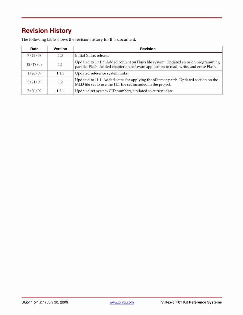
To view the Ethernet configuration settings, use the command ifconfig. Example results of using this command for the eth0 (Ethernet) and lo (Local Loopback) ports are shown in Figure 3-7. In the figure, the board IP address is 192.168.0.126. The board IP address can be manually set or changed by issuing the command ifconfig eth0 IP_address.
To ping a remote computer from the development board, the command string, ping -c 4 remote_computer_IP_address, is used to ping the remote computer 4 times.
X-Ref Target - Figure 3-7
Figure 3-7: Ethernet Configuration Settings
UG511_03_02_070108
36 www.xilinx.com Virtex-5 FXT Kit Reference SystemsUG511 (v1.2.1) July 30, 2009
Chapter 3: LynuxWorks BlueCat LinuxR
To FTP from a networked computer to the board, issue the command ftp board_IP_address. Files can now be transferred back and forth via FTP.
To telnet from a networked computer to the board, issue the command telnet board_IP_address. All of the Linux commands can now be performed remotely as if the user was logged into the console on a HyperTerminal.
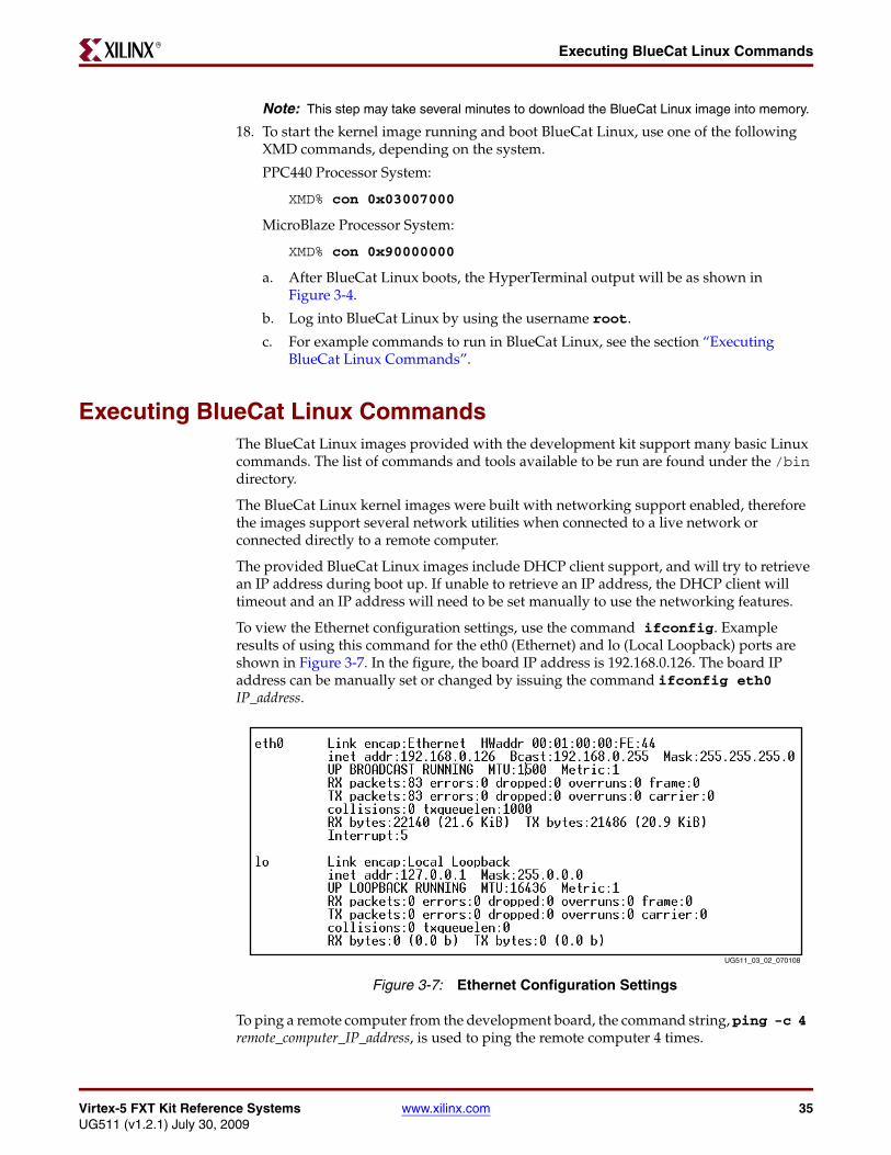
Web Server DemonstrationThe kernel images provided with the kit include the ability to run the Apache Web server. During boot up, the Web server will begin to run. The user can view the Web page from the Web server by going to http://<board_ip_address>. The Web page that is served is shown in Figure 3-8. On the Web page, the user can interact with the LEDs and the switches on the board. To set the LEDs, enter in a one or two digit hexadecimal number, then press SetLEDs. This will display the binary equivalent of the number on the LEDs. The Web page will also display the value of the DIP switches. Change the DIP switches on the board, then press the ReadSwitches button to update the Web page with the new switches value in binary.X-Ref Target - Figure 3-8
Figure 3-8: Web Page Displayed by the Web Server
UG511_03_03_070108

Virtex-5 FXT Kit Reference Systems www.xilinx.com 37UG511 (v1.2.1) July 30, 2009
Building the BlueCat Linux Kernel ImageR
Building the BlueCat Linux Kernel ImageThis section briefly describes the process for rebuilding the kernel image that is included with this reference system. To rebuild the kernel, the BlueCat Linux distribution must be obtained from LynuxWorks. For more information on the LynuxWorks BlueCat Linux distribution, see the BlueCat Linux User’s Guide for Release 5.4.
Building the BlueCat Linux kernel image for the PowerPC 440 processor system requires the BlueCat Linux core components for the PPC and the ML507 Board Support Package (BSP). For more information on the ML507 BSP, see the BlueCat Linux Board Support Guide for Xilinx ML507 Virtex-5 FXT Boards.
Building the BlueCat Linux kernel image for the MicroBlaze processor system requires the BlueCat Linux core components for the MicroBlaze processor and the Spartan-3E BSP. For more information on the Spartan-3E BSP, see the BlueCat Linux Board Support Guide for Xilinx Spartan-3E 1600E Boards.
The BlueCat Linux User’s Guide, the BlueCat Linux Board Support Guide for Xilinx ML507 Virtex-5 FXT Boards, and the BlueCat Linux Board Support Guide for Xilinx Spartan-3E 1600E Boards can be obtained from LynuxWorks at: http://www.lynuxworks.com/support/bluecat/docs.php3
These steps assume the kernel is being built on a host system running Red Hat Enterprise Linux 4.0. All of the Linux commands must be run using a bash shell.
Installing the BlueCat Linux DistributionThese steps describe how to install the BlueCat Linux core components and the BSP. For more information on the directory structures of the LynuxWorks BlueCat Linux distribution and the installation procedures, see the BlueCat Linux User’s Guide referenced above.
1. To install the BlueCat Linux core components on the host machine, follow the steps outlined in the “Installing the Default Configuration” section in the Introduction and Installation chapter of the BlueCat Linux User’s Guide.
2. To install the BSP on the host machine, follow the steps outlined in the “Installing Target Board Support” section in the Introduction and Installation chapter of the BlueCat Linux User’s Guide.
Note: When running the commands in these steps, bsp = ml507 for the PPC440 processor system or bsp = sp3e for the MicroBlaze processor system.
3. After the BSP is installed, support for it must be activated in the bash shell. To activate the BSP, follow the steps in the “Activating Support for a Target Board” section in the Introduction and Installation chapter of the BlueCat Linux User’s Guide.
Using the Provided Demo DirectoriesBlueCat Linux demo directories are provided with the reference systems which will allow the user to rebuild the BlueCat Linux images that are included. These demo directories can be found in <project root directory>/bclinux_demo/. These directories should be unzipped and placed in the BlueCat Linux distribution in $BLUECAT_PREFIX/demo/. The provided demo directories can be built similar to the LynuxWorks BlueCat Linux demos in the BlueCat Linux development environment. In each EDK project, there are two zipped demo directories. The v5fxt_devl_kit_demo.zip file is the demo directory to recreate the BlueCat Linux image that boots with a ramdisk file system. The

38 www.xilinx.com Virtex-5 FXT Kit Reference SystemsUG511 (v1.2.1) July 30, 2009
Chapter 3: LynuxWorks BlueCat LinuxR
v5fxt_devl_kit_demo_flash.zip file is the demo directory to recreate the BlueCat Linux image that boots with a JFFS2 file system.
Getting the MLD File SetThe MLD file set is included in the project directory at <project root directory/bsp/linux_bc54_v1_00_a/. This MLD file set is for building BlueCat Linux images on a Linux host computer.
Generating the BSPWith the use of the BlueCat Linux MLD, XPS can update the BlueCat Linux kernel source tree to match a specific hardware configuration. Follow these steps to generate the BSP and update the BlueCat Linux kernel source tree.
1. Open the reference system in XPS.
2. Select Software → Software Platform Settings... under XPS.
3. In the Software Platform Settings window, select linux_bc54 in the OS field, as shown in Figure 3-9.
4. Select the OS and Libraries option on the left of the Software Platform Settings window. Fill in the fields as follows:
BLUECAT_PREFIX:
<BlueCat_Linux_install_point>/usr/src/linux
KERNEL_CONFIG:
Ramdisk file system:
X-Ref Target - Figure 3-9
Figure 3-9: Select BlueCat Linux for the OS
UG511_03_04_070108

Virtex-5 FXT Kit Reference Systems www.xilinx.com 39UG511 (v1.2.1) July 30, 2009
Building the BlueCat Linux Kernel ImageR
<BlueCat_Linux_install_point>/demo/v5fxt_devl_kit_demo/v5fxt_devl_kit_demo.config
Flash file system:
<BlueCat_Linux_install_point>/demo/v5fxt_devl_kit_demo_flash/v5fxt_devl_kit_demo_flash.config
An example showing these fields for the ramdisk file system is in Figure 3-10.
5. Click OK to save the changes and close the Software Platform Settings window.
6. In XPS, select Software → Generate Libraries and BSPs. This will update the BlueCat Linux kernel source tree.
Rebuilding the Kernel ImageThis is the final step to create a bootable BlueCat Linux kernel image. To recreate the image provided with this reference system, follow these steps:
1. Two patches are provided with the reference systems. The cfi_patch allows the Flash memory to be used to hold a file system without chip errors. The xlltemac_patch makes the xlltemac driver compatible with v2.00.a of the XPS LL TEMAC core. The patches are located in the /bclinux_demo directory in the project. The patch files must be copied to the BlueCat Linux installation location, $BLUECAT_PREFIX, then the patches can be applied.
BlueCat:$ cd $BLUECAT_PREFIX
BlueCat:$ cp <project root directory/bclinux_demo/cfi_patch .
X-Ref Target - Figure 3-10
Figure 3-10: Set the BlueCat Linux Paths
UG511_03_05_070108

40 www.xilinx.com Virtex-5 FXT Kit Reference SystemsUG511 (v1.2.1) July 30, 2009
Chapter 3: LynuxWorks BlueCat LinuxR
BlueCat:$ cp <project root directory/bclinux_demo/xlltemac_patch .
BlueCat:$ patch -p0 < cfi_patch
BlueCat:$ patch -p0 < xlltemac_patch
2. To force all kernel components to rebuild, clean the kernel tree using the following commands:
BlueCat:$ cd $BLUECAT_PREFIX/usr/src/linux
BlueCat:$ make mrproper
3. Navigate to the appropriate demo directory.
Ramdisk file system:
BlueCat:$ cd $BLUECAT_PREFIX/demo/v5fxt_devl_kit_demo
Flash file system:
BlueCat:$ cd $BLUECAT_PREFIX/demo/v5fxt_devl_kit_demo_flash
4. Run the following command to see the menu for the Linux kernel configuration:
BlueCat:$ make menuconfig
5. To rebuild the Linux image that uses the JFFS2 Flash file system, ensure that the kernel configuration has enabled support for JFFS2. Navigate the menu to File Systems → Miscellaneous filesystems. Select the menu item to include Journalling Flash File System v2 (JFFS2) support. Under the main menu, navigate to Device Drivers → Memory Technology Devices (MTD). Select the menu item to include Memory Technology Device (MTD) support. Under MTD support, select the menu item to include MTD partitioning support.
6. Under the Linux kernel configuration menu, make sure that support is enabled for General setup → System V IPC. The Apache Web server requires this support.
7. Exit the Linux kernel configuration menu, saving the new configuration if changes were made.
8. Clean any prebuilt image files.
BlueCat:$ make clean
9. Build the kernel, root filesystem, and bootable image file.
BlueCat:$ make all
This command produces a .kdi file which is the BlueCat Linux image and is composed of a compressed kernel image and a compressed RAM disk root file system. The image will be stored in one of the following locations, depending on which demo was built.
Ramdisk file system:
$BLUECAT_PREFIX/demo/v5fxt_devl_kit_demo/v5fxt_devl_kit_demo.kdi
Flash file system:
$BLUECAT_PREFIX/demo/v5fxt_devl_kit_demo_flash/v5fxt_devl_kit_demo_flash.kdi
10. To run the newly created kernel image, refer to the steps in the section “Executing the BlueCat Linux Images”. When downloading the kernel image through XMD into DDR
Virtex-5 FXT Kit Reference Systems www.xilinx.com 41UG511 (v1.2.1) July 30, 2009
Booting the BlueCat Linux Image from Parallel FlashR
memory, put in the path to the new kernel image instead of the path to the pre-built kernel image in the bclinux_images directory.
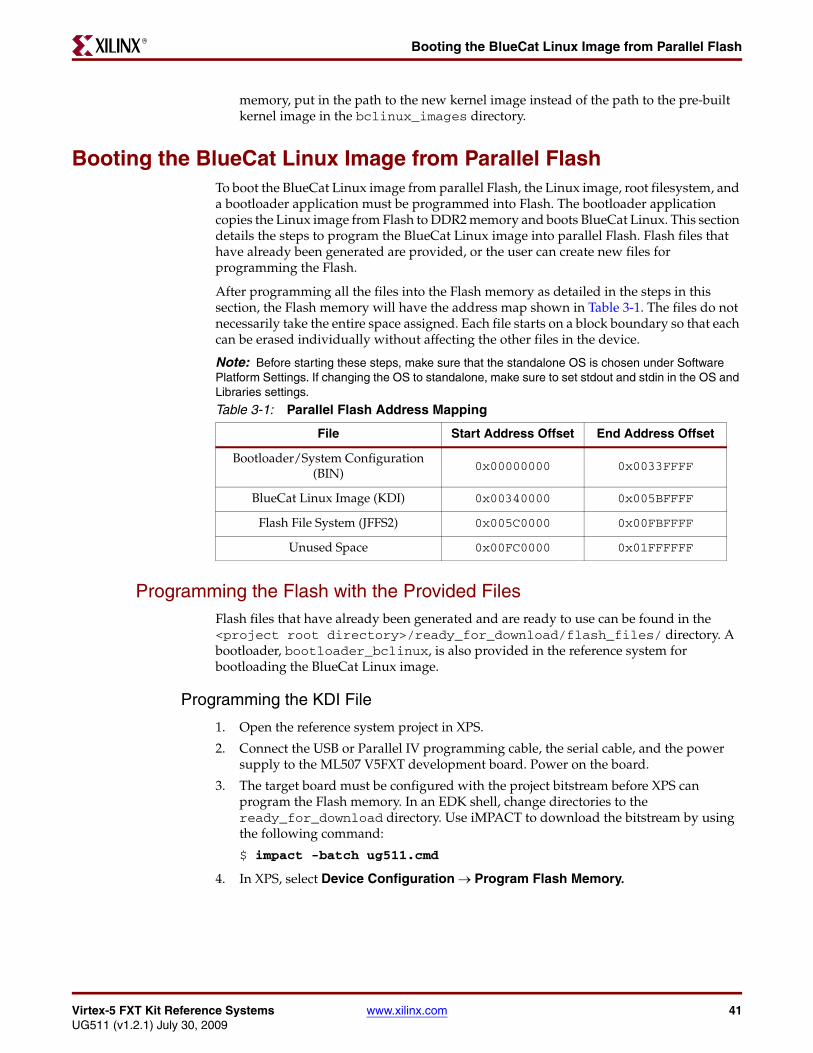
Booting the BlueCat Linux Image from Parallel FlashTo boot the BlueCat Linux image from parallel Flash, the Linux image, root filesystem, and a bootloader application must be programmed into Flash. The bootloader application copies the Linux image from Flash to DDR2 memory and boots BlueCat Linux. This section details the steps to program the BlueCat Linux image into parallel Flash. Flash files that have already been generated are provided, or the user can create new files for programming the Flash.
After programming all the files into the Flash memory as detailed in the steps in this section, the Flash memory will have the address map shown in Table 3-1. The files do not necessarily take the entire space assigned. Each file starts on a block boundary so that each can be erased individually without affecting the other files in the device.
Note: Before starting these steps, make sure that the standalone OS is chosen under Software Platform Settings. If changing the OS to standalone, make sure to set stdout and stdin in the OS and Libraries settings.
Programming the Flash with the Provided FilesFlash files that have already been generated and are ready to use can be found in the <project root directory>/ready_for_download/flash_files/ directory. A bootloader, bootloader_bclinux, is also provided in the reference system for bootloading the BlueCat Linux image.
Programming the KDI File
1. Open the reference system project in XPS.
2. Connect the USB or Parallel IV programming cable, the serial cable, and the power supply to the ML507 V5FXT development board. Power on the board.
3. The target board must be configured with the project bitstream before XPS can program the Flash memory. In an EDK shell, change directories to the ready_for_download directory. Use iMPACT to download the bitstream by using the following command:
$ impact -batch ug511.cmd
4. In XPS, select Device Configuration → Program Flash Memory.
Table 3-1: Parallel Flash Address Mapping
File Start Address Offset End Address Offset
Bootloader/System Configuration (BIN)
0x00000000 0x0033FFFF
BlueCat Linux Image (KDI) 0x00340000 0x005BFFFF
Flash File System (JFFS2) 0x005C0000 0x00FBFFFF
Unused Space 0x00FC0000 0x01FFFFFF

42 www.xilinx.com Virtex-5 FXT Kit Reference SystemsUG511 (v1.2.1) July 30, 2009
Chapter 3: LynuxWorks BlueCat LinuxR
5. In the Program Flash Memory dialog box, choose the file to program to be /bclinux_images/v5fxt_devl_kit_demo_flash.kdi under the project root directory. Change the program offset to 0x00340000, which will allow enough room for the bootloader and will not overwrite the location that BlueCat Linux expects the Flash file system. The external DDR2 memory is set as the Scratch Memory. The Program Flash Memory settings are shown in Figure 3-11.
Note: The bootloader provided in the bootloader_bclinux directory assumes the image has been programmed at an offset of 0x00340000.
6. Click the OK button. This will program the flash memory with the BlueCat Linux image.
Note: The Program Flash Memory application will take a long time as the application must program the image of size approximately 2 MB.
X-Ref Target - Figure 3-11
Figure 3-11: Program Flash Memory Dialog Box for BlueCat Linux Image
UG511_03_16_121208

Virtex-5 FXT Kit Reference Systems www.xilinx.com 43UG511 (v1.2.1) July 30, 2009
Booting the BlueCat Linux Image from Parallel FlashR
Programming the BIN File
The next step is to program the BIN file for the system. The BIN file is used to program the Flash with the system bitstream and bootloader loaded in the bitstream.
1. From the XPS menu, select Device Configuration → Program Flash Memory.
2. In the Program Flash Memory dialog box, choose the file to program to be bootloader_bclinux.bin under the ready_for_download/flash_files directory of the project. Change the program offset to 0x00000000. The external DDR2 memory is set as the Scratch Memory. The Program Flash Memory settings are shown in Figure 3-12..
3. Click the OK button. This will program the flash memory with the bitstream and bootloader loaded in the bitstream.
X-Ref Target - Figure 3-12
Figure 3-12: Program Flash Memory Box for the Bootloader and Bitstream BIN File
UG511_03_17_121208

44 www.xilinx.com Virtex-5 FXT Kit Reference SystemsUG511 (v1.2.1) July 30, 2009
Chapter 3: LynuxWorks BlueCat LinuxR
Note: The Program Flash Memory application will take a long time as the application must program the BIN file of size approximately 3 MB.
Programming the Root File System
1. In an EDK shell, change directories to the ready_for_download directory.
2. Invoke XMD and connect to the processor by the following command:
$ xmd -opt ug511.opt
3. Download the FlashRWE software application into BRAM using the following command:
XMD% dow flashrwe_executable.elf
4. To start the FlashRWE software application running, use the following XMD command:
XMD% run
After the FlashRWE software application runs, the HyperTerminal will display the Main Menu.
5. With the FlashRWE program, erase blocks 46-125 of Flash. These blocks are the location that the BlueCat Linux kernel image will expect the JFFS2 root file system. To erase the blocks, perform the following steps, as shown in Figure 3-13.
a. Enter 3 at the Main Menu.
b. In the Flash Erase Menu, enter 2.
c. Enter 46 as the starting block.
d. Enter 125 as the ending block.
6. In XMD, stop and reset the processor. Then, exit XMD.
XMD% stop
XMD% rst
XMD% exit
X-Ref Target - Figure 3-13
Figure 3-13: Erase Blocks 46-125 of the Flash
UG511_03_14_121208

Virtex-5 FXT Kit Reference Systems www.xilinx.com 45UG511 (v1.2.1) July 30, 2009
Booting the BlueCat Linux Image from Parallel FlashR
7. In XPS, select Device Configuration → Program Flash Memory.
8. In the Program Flash Memory dialog box, choose the file to program to be <project root directory>/bclinux_images/v5fxt_devl_kit_demo_flash.jffs2. Enter the offset to be 0x005C0000. The external DDR2 memory is set as the Scratch Memory. The Program Flash Memory settings are shown in Figure 3-14.
9. Click the OK button. This will program the flash memory with the JFFS2 file.
Note: The Program Flash Memory application will take a long time as the application must program the JFFS2 file of size approximately 7 MB.
Running the Design
1. Once the Flash is programmed with all the files documented in the previous steps, change the configuration address / mode DIP switches to 00001001.
X-Ref Target - Figure 3-14
Figure 3-14: Program Flash Memory Box for the JFFS2 File System
UG511_03_15_121208

46 www.xilinx.com Virtex-5 FXT Kit Reference SystemsUG511 (v1.2.1) July 30, 2009
Chapter 3: LynuxWorks BlueCat LinuxR
2. Press the Prog button. The design takes about 10 seconds to finish loading and begin to run.
Generating New Flash Files and Programming the FlashInstead of using the pregenerated files, the user can generate new files for programming the Flash device. This section details the steps for creating new Flash files and programming them into the Flash device.
Programming the KDI File and Creating the Bootloader
1. Open the reference system project in XPS.
2. Connect the USB or Parallel IV programming cable, the serial cable, and the power supply to the ML507 V5FXT development board. Power on the board.
3. The target board must be configured with the project bitstream before XPS can program the SREC file into the flash memory. Select Device Configuration → Download Bitstream in XPS.
4. In XPS, select Device Configuration → Program Flash Memory.
In the Program Flash Memory dialog box, choose the file to program to be /bclinux_images/v5fxt_devl_kit_demo_flash.kdi under the project root directory. Change the program offset to 0x00340000, which will allow enough room for the bootloader and will not overwrite the location that BlueCat Linux expects the Flash file system.

Virtex-5 FXT Kit Reference Systems www.xilinx.com 47UG511 (v1.2.1) July 30, 2009
Booting the BlueCat Linux Image from Parallel FlashR
The external DDR2 memory is set as the Scratch Memory. A bootloader is created by clicking the Create Flash Bootloader Application check box in the Program Flash Memory dialog box. The Program Flash Memory settings are shown in Figure 3-15.
Note: The bootloader provided in the bootloader_bclinux directory assumes the image has been programmed at an offset of 0x00340000.
5. Click the OK button. This will program the flash memory with the BlueCat Linux image and will create a bootloader software application project.
Note: The Program Flash Memory application will take a long time as the application must program the image of size approximately 2 MB.
6. After creating the bootloader files, add the following lines, shown in Figure 3-16, in the bootloader.c file:
#include "xparameters.h"#include "xuartns550_l.h"
X-Ref Target - Figure 3-15
Figure 3-15: Program Flash Memory Dialog Box for BlueCat Linux Image
UG511_03_18_121208

48 www.xilinx.com Virtex-5 FXT Kit Reference SystemsUG511 (v1.2.1) July 30, 2009
Chapter 3: LynuxWorks BlueCat LinuxR
7. It is strongly suggested to disable the bootloader from displaying its progress. This is done by commenting out the following line in the bootloader.c generated file:
#define VERBOSE
The line to comment out to allow non-verbose bootloading is shown inFigure 3-16.
8. The bootloader must be modified to copy the KDI image from Flash into DDR2 for the BlueCat Linux demonstration to fully operate. This is done by adding lines of code to the bootloader.c file that the EDK generates. To modify the newly created bootloader, add the following pieces of code:
a. Code is required to define the location in Flash where the KDI image resides and the location in DDR to put the KDI image. This code is shown in Figure 3-17. The KDI_FLASH_LOC parameter should be set to the location in Flash memory of where the KDI image will be placed.The KDI_DDR_LOC parameter should be set to the location in DDR2 memory where the KDI image is to be copied. The KDI_LENGTH parameter should be set to the length of the KDI image in bytes.
Note: Figure 3-17 shows the code for the PPC440 system. Some of the parameters have different values for the MicroBlaze processor system and can be seen in the example code provided for the MicroBlaze processor system.
b. Comment the SREC function load_exec in the source file as the KDI image is loaded as it is to the FLASH memory and so these functions are not required. Code is also required for the bootloader to copy the KDI image from flash into DDR2 when the bootloader runs. This code is shown in Figure 3-18. After modifying the C file, be sure to recompile the software application.
Note: Figure 3-18 shows the code for the PPC440 system. The MicroBlaze processor system has a different address to execute from and therefore the code is slightly different. The
X-Ref Target - Figure 3-16
Figure 3-16: Code to Select Non-Verbose Bootloading
X-Ref Target - Figure 3-17
Figure 3-17: BlueCat Linux Bootloader Code Definitions and Declarations
UG511_03_19_121208
UG511_03_20_121208

Virtex-5 FXT Kit Reference Systems www.xilinx.com 49UG511 (v1.2.1) July 30, 2009
Booting the BlueCat Linux Image from Parallel FlashR
bootloader code for the MicroBlaze processor can be found in the MicroBlaze processor reference system.
9. In XPS, compile a bitstream download.bit, that includes the system configuration and the bootloader_bclinux application. This is done by marking the bootloader application to Initialize BRAM’s, then selecting Device Configuration → Update Bitstream in XPS.
Creating and Programming the BIN File
Once the bootloader application is created, the next step is to create the BIN file for the system. The BIN file is used to program the Flash with the system bitstream and bootloader loaded in the bitstream.
1. In XPS, open an EDK shell.
2. Create a BIN file to program the Flash device by issuing the following command in the project root directory:
$ promgen -w -p bin -o bootloader_bclinux.bin -u 0 implementation/download.bit
3. From the XPS menu, select Device Configuration → Program Flash Memory.
X-Ref Target - Figure 3-18
Figure 3-18: BlueCat Linux Bootloader Code to Copy the KDI Image
UG511_03_09_070108

50 www.xilinx.com Virtex-5 FXT Kit Reference SystemsUG511 (v1.2.1) July 30, 2009
Chapter 3: LynuxWorks BlueCat LinuxR
4. In the Program Flash Memory dialog box, choose the file to program to be <project root directory>/bootloader_bclinux.bin. Change the program offset to 0x00000000. The external DDR2 memory is set as the Scratch Memory. The Program Flash Memory settings are shown in Figure 3-19.
5. Click the OK button. This will program the flash memory with the bitstream and bootloader loaded in the bitstream.
Note: The Program Flash Memory application will take a long time as the application must program the BIN file of size approximately 3 MB.
Programming the Root File System
1. In an EDK shell, change directories to the ready_for_download directory.
2. Invoke XMD and connect to the processor by the following command:
X-Ref Target - Figure 3-19
Figure 3-19: Program Flash Memory Box for the Bootloader and Bitstream BIN File
UG511_03_21_121208

Virtex-5 FXT Kit Reference Systems www.xilinx.com 51UG511 (v1.2.1) July 30, 2009
Booting the BlueCat Linux Image from Parallel FlashR
$ xmd -opt ug511.opt
3. Download the FlashRWE software application into BRAM using the following command:
XMD% dow flashrwe_executable.elf
4. To start the FlashRWE software application running, use the following XMD command:
XMD% run
After the FlashRWE software application runs, the HyperTerminal will display the Main Menu.
5. With the FlashRWE program, erase blocks 46-125 of Flash. These blocks are the location that the BlueCat Linux kernel image will expect the JFFS2 root file system. To erase the blocks, perform the following steps, as shown in Figure 3-20.
a. Enter 3 at the Main Menu.
b. In the Flash Erase Menu, enter 2.
c. Enter 46 as the starting block.
d. Enter 125 as the ending block.
6. In XMD, stop and reset the processor. Then, exit XMD.
XMD% stop
XMD% rst
XMD% exit
7. In XPS, select Device Configuration → Program Flash Memory.
8. In the Program Flash Memory dialog box, choose the file to program to be /bclinux_images/v5fxt_devl_kit_demo_flash.jffs2. Enter the offset to be
X-Ref Target - Figure 3-20
Figure 3-20: Erase Blocks 46-125 of the Flash
UG511_03_22_121208

52 www.xilinx.com Virtex-5 FXT Kit Reference SystemsUG511 (v1.2.1) July 30, 2009
Chapter 3: LynuxWorks BlueCat LinuxR
0x005C0000. The external DDR2 memory is set as the Scratch Memory. The Program Flash Memory settings are shown in Figure 3-21.
9. Click the OK button. This will program the flash memory with the JFFS2 file.
Note: The Program Flash Memory application will take a long time as the application must program the JFFS2 file of size approximately 7 MB.
Running the Design
1. Once the Flash is programmed with all the files documented in the previous steps, change the configuration address / mode DIP switches to 00001001.
2. Press the Prog button. The design takes about 10 seconds to finish loading and begin to run.
X-Ref Target - Figure 3-21
Figure 3-21: Program Flash Memory Box for the JFFS2 File System
UG511_03_23_121208
Virtex-5 FX70T Kit Reference Systems www.xilinx.com 53UG511 (v1.2.1) July 30, 2009
R
Chapter 4
FlashRWE Software Application
IntroductionThe FlashRWE software application provides functions to read, write, and erase, the parallel Flash device. When the application is run, it will print a menu with options to enter the read, write, or erase menus. The FlashRWE application uses the xilflash library. The FlashRWE software application can run on either the MicroBlaze processor or the PowerPC 440 processor reference system.
To download and run the FlashRWE software application:
• Download the executable file directly into BRAM using a debugger, such as XMD, which is provided as part of the EDK tools. The proces is described in the section “Executing the FlashRWE Software Application”.
Note: A warning box will appear during some of the steps in this chapter. The warning box states that “Software development features in XPS are deprecated, and will be removed in the next major release”. Click OK to safely ignore this warning. To turn off this warning completely, navigate to Edit→Preferences in XPS. Select Application Preferences and check the box that states “Do not show “Software Features Deprecated” dialog box”.
Executing the FlashRWE Software ApplicationTo execute the FlashRWE software application, program the hardware bitstream to the Virtex-5 FX device and load the FlashRWE software application into BRAM. Program the bitstream by downloading the pre-built bitstream from the ready_for_download directory or generate and download it from XPS. Similarly, the FlashRWE executable can be downloaded from the ready_for_download directory or built and downloaded through XPS.
Executing the FlashRWE Application Using the Pre-Built BitstreamTo execute the application using the files in the ready_for_download directory in the project root directory, follow these steps:
1. Connect the Platform USB cable or the Parallel IV JTAG cable between the host computer and the Virtex-5 FX70T ML507 development board.
2. Connect the serial cable between the host computer and the RS232 port on the Virtex-5 FX70T ML507 development board.
3. Apply power to the Virtex-5 FX70T ML507 development board.

54 www.xilinx.com Virtex-5 FX70T Kit Reference SystemsUG511 (v1.2.1) July 30, 2009
Chapter 4: FlashRWE Software ApplicationR
4. Start a HyperTerminal (or similar) session on the host computer with the settings shown in Figure 4-1. Select the COM port corresponding to the connected serial port on the host computer. Set the Baud Rate to 115200, Data bits to 8 bits, Parity to None, Stop bits to 1 bit, and Flow control to None.
5. Through XPS, launch an EDK shell by selecting Project → Launch EDK Shell.
6. In the EDK shell, change directories to the ready_for_download directory in either the MicroBlaze processor or the PowerPC processor reference system.
7. Use iMPACT to download the bitstream by using the following command:
$ impact -batch ug511.cmd
8. Invoke XMD and connect to the processor by using the following command:
$ xmd -opt ug511.opt
9. Download the FlashRWE software application into BRAM by using the following command:
XMD% dow flashrwe_executable.elf
X-Ref Target - Figure 4-1
Figure 4-1: HyperTerminal Settings
UG511_04_01_121208

Virtex-5 FX70T Kit Reference Systems www.xilinx.com 55UG511 (v1.2.1) July 30, 2009
Functions in the FlashRWE Software ApplicationR
10. Start the FlashRWE software application running by using the following XMD command:
XMD% run
a. After the FlashRWE software application runs, the HyperTerminal will display the Main Menu, as shown in Figure 4-2, page 55.
b. For an explanation of the available functionality in the application, see the section “Functions in the FlashRWE Software Application”.
Executing the FlashRWE Software Application from XPSTo execute the reference system using XPS, follow these steps:
1. Perform steps 1-4 in the “Executing the FlashRWE Application Using the Pre-Built Bitstream” section.
2. Open either the MicroBlaze processor or the PowerPC 440 processor reference system project in XPS.
3. Implement the hardware design and create the hardware bitstream by selecting Hardware → Generate Bitstream in XPS.
4. In the Applications tab, build the FlashRWE project by right-clicking on the project and selecting Build Project. This will create the software executable for the application.
5. Download the bitstream to the board by selecting Device Configuration → Download Bitstream in XPS.
6. After the bitstream has downloaded, launch the XMD by selecting Debug → Launch XMD... in XPS.
7. Download the FlashRWE application executable file using the following command in XMD:
XMD% dow FlashRWE/executable.elf
8. To run the software application, use the run command in XMD.
a. After the FlashRWE software application runs, the HyperTerminal will display the Main Menu, as shown in Figure 4-2, page 55.
b. For an explanation of the available commands in the application, see the section “Functions in the FlashRWE Software Application”.
Functions in the FlashRWE Software ApplicationAfter the FlashRWE application is executed, the Main Menu will be printed out to the terminal application. The Main Menu is shown in Figure 4-2. The Main Menu allows the options to enter into the read, write, and erase submenus.X-Ref Target - Figure 4-2
Figure 4-2: Main Menu
UG511_04_02_121208

56 www.xilinx.com Virtex-5 FX70T Kit Reference SystemsUG511 (v1.2.1) July 30, 2009
Chapter 4: FlashRWE Software ApplicationR
Table 4-1 lists and describes the functions that are available in the FlashRWE application.
Table 4-1: Summary of the Available Functions in the FlashRWE Application
Submenu Function DescriptionParameters Entered by
UserDocument Link
Flash Read
Read Bytes of Flash
Read and print out individual bytes of data from the parallel Flash device.
Address offset, Number of bytes
“Read Bytes of Flash,” page 57
Check if Flash is Empty
Checks all bytes of data in the parallel Flash device and determines if the Flash device is fully erased.
None“Check if Flash is Empty,” page 57
Exit to Main Menu
Exit the submenu and return to the main menu
None N/A
Flash Write
Write Incrementing Numbers to
Flash
Write incrementing numbers, 0x0-0xFF to
bytes in the Flash.
Address offset, Number of
bytes
“Write Incrementing Numbers to
Flash,” page 59
Write Bytes to Flash
Write bytes of data to Flash
Address offset, Bytes of data,
Number of times to write
the data
“Write Bytes to Flash,” page 60
Exit to Main Menu
Exit the submenu and return to the main
menuNone N/A
Flash Erase
Erase Bytes of Flash
Erases the block(s) of Flash that the specified
bytes reside in
Address offset, Number of
bytes
“Erase Bytes of Flash,” page 61
Erase Blocks of Flash
Erases a single block or a range of consecutive
blocks of Flash
Starting block, Ending block
“Erase Blocks of Flash,” page 62
Erase the Entire Flash
Erases the entire Flash device
None“Erase the Entire Flash,” page 63
Exit to Main Menu
Exit the submenu and return to the main
menuNone N/A
None (Main menu)
Exit the Flash Program
Quits the FlashRWE program
None N/A
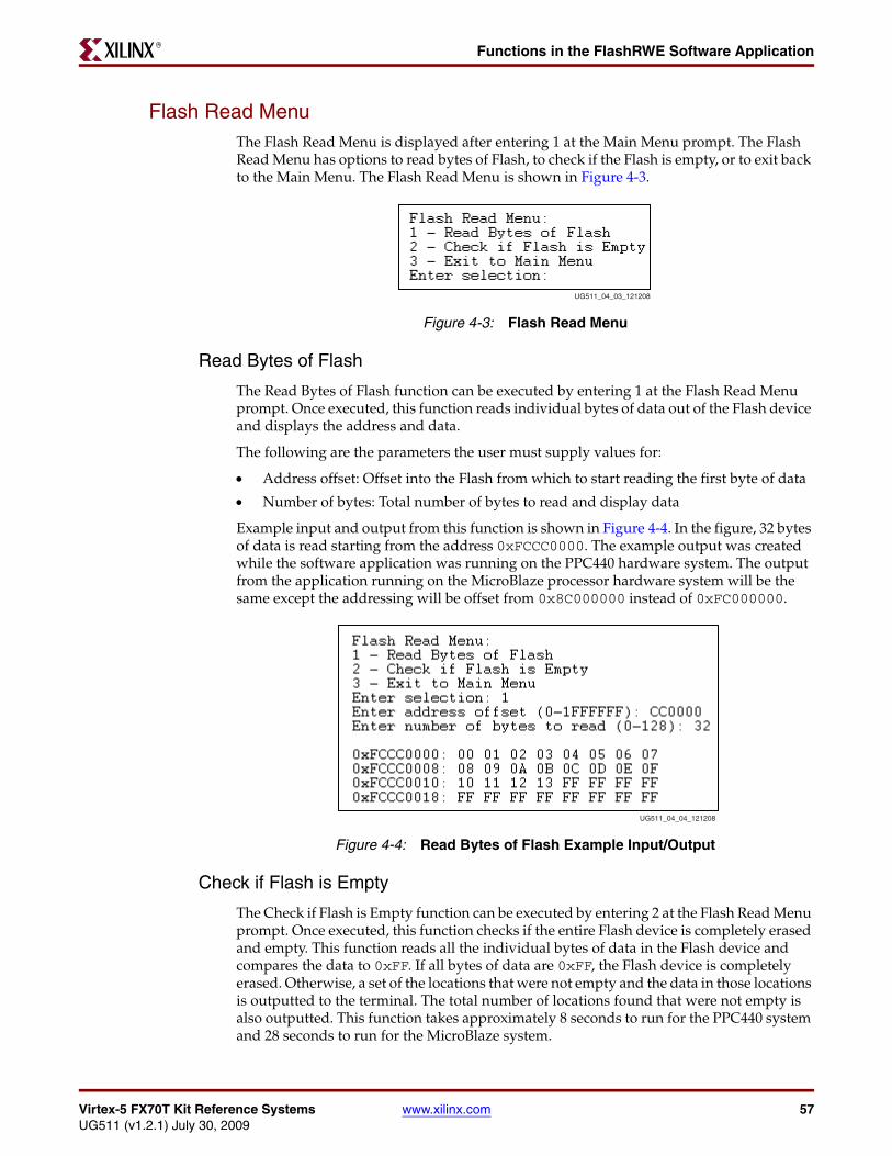
Virtex-5 FX70T Kit Reference Systems www.xilinx.com 57UG511 (v1.2.1) July 30, 2009
Functions in the FlashRWE Software ApplicationR
Flash Read MenuThe Flash Read Menu is displayed after entering 1 at the Main Menu prompt. The Flash Read Menu has options to read bytes of Flash, to check if the Flash is empty, or to exit back to the Main Menu. The Flash Read Menu is shown in Figure 4-3.
Read Bytes of Flash
The Read Bytes of Flash function can be executed by entering 1 at the Flash Read Menu prompt. Once executed, this function reads individual bytes of data out of the Flash device and displays the address and data.
The following are the parameters the user must supply values for:
• Address offset: Offset into the Flash from which to start reading the first byte of data
• Number of bytes: Total number of bytes to read and display data
Example input and output from this function is shown in Figure 4-4. In the figure, 32 bytes of data is read starting from the address 0xFCCC0000. The example output was created while the software application was running on the PPC440 hardware system. The output from the application running on the MicroBlaze processor hardware system will be the same except the addressing will be offset from 0x8C000000 instead of 0xFC000000.
Check if Flash is Empty
The Check if Flash is Empty function can be executed by entering 2 at the Flash Read Menu prompt. Once executed, this function checks if the entire Flash device is completely erased and empty. This function reads all the individual bytes of data in the Flash device and compares the data to 0xFF. If all bytes of data are 0xFF, the Flash device is completely erased. Otherwise, a set of the locations that were not empty and the data in those locations is outputted to the terminal. The total number of locations found that were not empty is also outputted. This function takes approximately 8 seconds to run for the PPC440 system and 28 seconds to run for the MicroBlaze system.
X-Ref Target - Figure 4-3
Figure 4-3: Flash Read Menu
UG511_04_03_121208
X-Ref Target - Figure 4-4
Figure 4-4: Read Bytes of Flash Example Input/Output
UG511_04_04_121208

58 www.xilinx.com Virtex-5 FX70T Kit Reference SystemsUG511 (v1.2.1) July 30, 2009
Chapter 4: FlashRWE Software ApplicationR
Figure 4-5 shows example output from the function when the Flash is empty. Figure 4-6 shows example output from the function when the Flash is not empty. The example output was created while the software application was running on the PPC440 hardware system. The output from the application running on the MicroBlaze processor hardware system will be the same except the addressing will be offset from 0x8C000000 instead of 0xFC000000.X-Ref Target - Figure 4-5
Figure 4-5: Check if Flash is Empty Example Output - Flash is Empty
X-Ref Target - Figure 4-6
Figure 4-6: Check if Flash is Empty Example Output - Flash is not Empty
UG511_04_05_121208
UG511_04_06_121208

Virtex-5 FX70T Kit Reference Systems www.xilinx.com 59UG511 (v1.2.1) July 30, 2009
Functions in the FlashRWE Software ApplicationR
Flash Write MenuThe Flash Write Menu is displayed after entering 2 at the Main Menu prompt. The Flash Write Menu has options to write incrementing numbers to Flash, write bytes to Flash, or exit back to the Main Menu. The Flash Write Menu is shown in Figure 4-7.
Write Incrementing Numbers to Flash
The Write Incrementing Numbers to Flash function can be executed by entering 1 at the Flash Write Menu prompt. Once executed, this function writes incrementing numbers (0x0-0xFF) to bytes in the Flash. After reaching 0xFF, the function wraps back to 0x0 and continues writing incrementing numbers to bytes in the Flash. If there is data found in the Flash at the bytes specified for writing, the function will prompt the user to either erase the block(s) of Flash where the bytes reside or to cancel the write request.
The following are the parameters for which the user must supply values:
• Address offset: Offset into the Flash from which to start writing the first byte of data
• Number of bytes: Total number of bytes to write incrementing numbers
Figure 4-8 shows an example output from the function when the bytes to write are already empty. In Figure 4-8, 64 bytes of data is being written to address 0xFC100000. Figure 4-9 shows an example output from the function when the bytes to write have previously stored data. In Figure 4-9, 20 bytes of data were inputted to be written to address 0xFDA00000, but 6 bytes of Flash were found to have previous data. To proceed with the write, the user must allow the entire block (0xFDA00000-0xFDA1FFFF) to be erased. The example output was created while the software application was running on the PowerPC 440 processor hardware system. The output from the application running on the MicroBlaze processor hardware system will be the same, except that the addressing will be offset from 0x8C000000 instead of 0xFC000000
X-Ref Target - Figure 4-7
Figure 4-7: Flash Write Menu
UG511_04_07_121208
X-Ref Target - Figure 4-8
Figure 4-8: Write Incrementing Numbers Example Input and Output - Empty Bytes
UG511_04_08_121208

60 www.xilinx.com Virtex-5 FX70T Kit Reference SystemsUG511 (v1.2.1) July 30, 2009
Chapter 4: FlashRWE Software ApplicationR
Write Bytes to Flash
The Write Bytes to Flash function can be executed by entering 2 at the Flash Write Menu prompt. Once executed, this function writes bytes of data to Flash. If there is data found in the Flash at the bytes specified for writing, the function will prompt the user to either erase the block(s) of Flash where the bytes reside or to cancel the write request.
The following are the parameters for which the user must supply values:
• Address offset: Offset into the Flash from which to start writing the first byte of data
• Bytes of data: The actual data to write to bytes in Flash
• Number of times: The number of times to write the specified bytes of data
Figure 4-10 shows example input and output from the function when the bytes to write are already empty. In Figure 4-10, the data string 0x21436587 is being written 3 times starting at address 0xFDA00000. Figure 4-11 shows example input and output from the function when the bytes to write have previously stored data. In Figure 4-11, the data string 0xFEDCBA was input to be written 2 times to the address 0xFC100000, but 6 bytes of Flash were found to have previous data. To proceed with the write, the user must allow the entire block (0xFC100000-0xFC11FFFF) to be erased. The example output was created while the software application was running on the PowerPC 440 processor hardware system. The output from the application running on the MicroBlaze processor hardware system will be the same except that the addressing will be offset from 0x8C000000 instead of 0xFC000000.
X-Ref Target - Figure 4-9
Figure 4-9: Write Incrementing Numbers Example Input and Output - Full Bytes
UG511_04_09_121208
X-Ref Target - Figure 4-10
Figure 4-10: Write Bytes Example Input and Output - Empty Bytes
UG511_04_10_121208

Virtex-5 FX70T Kit Reference Systems www.xilinx.com 61UG511 (v1.2.1) July 30, 2009
Functions in the FlashRWE Software ApplicationR
Flash Erase MenuThe Flash Erase Menu is displayed after entering 3 at the Main Menu prompt. The Flash Erase Menu has options to erase bytes of Flash, erase blocks of Flash, erase the entire Flash, or exit back to the Main Menu. The Flash Erase Menu is shown in Figure 4-12.
Erase Bytes of Flash
The Erase Bytes of Flash function can be executed by entering 1 at the Flash Erase Menu prompt. Once executed, this function erases the block(s) of Flash in which the specified bytes reside.
The following are the parameters for which the user must supply values:
• Address offset: Offset into the Flash to the first byte desired to be erased
• Number of bytes: Total number of bytes to erase
Caution! Because Flash memory must be erased in blocks, the number of bytes actually erased may be larger than the inputted number of bytes to erase, depending on the address offset and number of bytes specified.
X-Ref Target - Figure 4-11
Figure 4-11: Write Bytes Example Input and Output - Full Bytes
UG511_04_11_121208
X-Ref Target - Figure 4-12
Figure 4-12: Flash Erase Menu
UG511_04_12_121208

62 www.xilinx.com Virtex-5 FX70T Kit Reference SystemsUG511 (v1.2.1) July 30, 2009
Chapter 4: FlashRWE Software ApplicationR
An example input and output from this function is shown in Figure 4-13. In the figure, it is specified to erase 2048 bytes at address 0xFC010000. However, because of Flash memory characteristics, the entire block in which these bytes reside, will be erased, namely the address range 0xFC000000-0xFC01FFFF. The example output was created while the software application was running on the PPC440 hardware system. The output from the application running on the MicroBlaze processor hardware system will be the same except that the addressing will be offset from 0x8C000000 instead of from 0xFC000000.
Erase Blocks of Flash
The Erase Blocks of Flash function can be executed by entering 2 at the Flash Erase Menu prompt. Once executed, this function erases the specified range of block(s) of Flash. If the maximum number of blocks (256 blocks) is specified to be erased, this function will take approximately 4 minutes to complete.
The following are the parameters for which the user must supply values:
• Starting block: First block in the range of blocks to be erased
• Ending block: Last block in the range of blocks to be erased
An example input and output from this function is shown in Figure 4-14. In the figure, blocks 35-104 have been erased, which corresponds to the address range 0xFC46000000-0xFCD1FFFF. The example output was created while the software application was running on the PowerPC 440 processor hardware system. The output from the application running on the MicroBlaze processor hardware system will be the same except the addressing will be offset from 0x8C000000 instead of 0xFC000000.
X-Ref Target - Figure 4-13
Figure 4-13: Erase Bytes of Flash Example Input and Output
UG511_04_13_121308
X-Ref Target - Figure 4-14
Figure 4-14: Erase Blocks of Flash Example Input and Output
UG511_04_14_121208

Virtex-5 FX70T Kit Reference Systems www.xilinx.com 63UG511 (v1.2.1) July 30, 2009
Functions in the FlashRWE Software ApplicationR
Erase the Entire Flash
The Erase the Entire Flash function can be executed by entering 3 at the Flash Erase Menu prompt. Once executed, this function erases the entire Flash device. The function will take approximately 4 minutes to complete.
Example output from this function is shown in Figure 4-15.X-Ref Target - Figure 4-15
Figure 4-15: Erase the Entire Flash Example Output
UG511_04_15_121208

64 www.xilinx.com Virtex-5 FX70T Kit Reference SystemsUG511 (v1.2.1) July 30, 2009
Chapter 4: FlashRWE Software ApplicationR