Embed Size (px)
Citation preview
Page 1 of 18
CANopen DIGITAL SERVOAMPLIFIERfor BRUSHLESS or BRUSH MOTORSXenus ™
LEDOM cI pI CAV
81-032-LSX 6 81
042~00163-032-LSX 21 63
04-032-LSX 02 04
••••• CANopen FeaturesNo motion-control card neededHigh Performance/Cost RatioSimplified CablingChange parameters on the fly
••••• Operates as a stand-aloneamplifier with motion controller
Position modePulse & directionCW/CCW inputsQuadrature encoder for electronic gearing
Torque or Velocity mode±10 Vdc AnalogPWM & Polarity50% PWM
••••• ProtectionsMotor
Over-TemperatureI2T Current Limiting
AmplifierCommunication errorsFeedback Power LossOver/under VoltageAmplifier Over-temperatureOutput short circuits
••••• CE Compliance:
89/336/EEC ElectromagneticEN 55011 CompatibilityEN 50082-1
98/37/EC Safety of MachineryEN 60204-1UL 508C
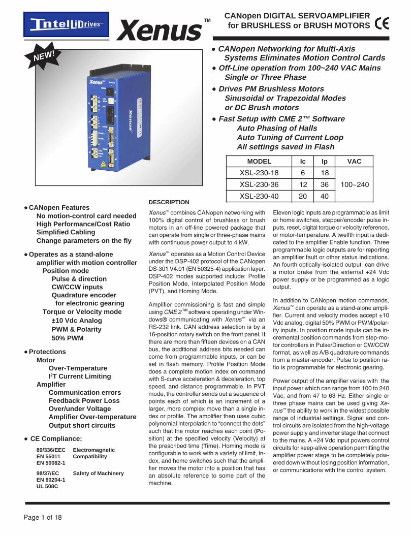
••••• CANopen Networking for Multi-AxisSystems Eliminates Motion Control Cards
••••• Off-Line operation from 100~240 VAC MainsSingle or Three Phase
••••• Drives PM Brushless MotorsSinusoidal or Trapezoidal Modesor DC Brush motors
DESCRIPTION
Xenus™ combines CANopen networking with100% digital control of brushless or brushmotors in an off-line powered package thatcan operate from single or three-phase mainswith continuous power output to 4 kW.
Xenus™ operates as a Motion Control Deviceunder the DSP-402 protocol of the CANopenDS-301 V4.01 (EN 50325-4) application layer.DSP-402 modes supported include: ProfilePosition Mode, Interpolated Position Mode(PVT), and Homing Mode.
Amplifier commissioning is fast and simpleusing CME 2™ software operating under Win-dows® communicating with Xenus™ via anRS-232 link. CAN address selection is by a16-position rotary switch on the front panel. Ifthere are more than fifteen devices on a CANbus, the additional address bits needed cancome from programmable inputs, or can beset in flash memory. Profile Position Modedoes a complete motion index on commandwith S-curve acceleration & deceleration, topspeed, and distance programmable. In PVTmode, the controller sends out a sequence ofpoints each of which is an increment of alarger, more complex move than a single in-dex or profile. The amplifier then uses cubicpolynomial interpolation to “connect the dots”such that the motor reaches each point (Po-sition) at the specified velocity (Velocity) atthe prescribed time (Time). Homing mode isconfigurable to work with a variety of limit, in-dex, and home switches such that the ampli-fier moves the motor into a position that hasan absolute reference to some part of themachine.
Eleven logic inputs are programmable as limitor home switches, stepper/encoder pulse in-puts, reset, digital torque or velocity reference,or motor-temperature. A twelfth input is dedi-cated to the amplifier Enable function. Threeprogrammable logic outputs are for reportingan amplifier fault or other status indications.An fourth optically-isolated output can drivea motor brake from the external +24 Vdcpower supply or be programmed as a logicoutput.
In addition to CANopen motion commands,Xenus™ can operate as a stand-alone ampli-fier. Current and velocity modes accept ±10Vdc analog, digital 50% PWM or PWM/polar-ity inputs. In position mode inputs can be in-cremental position commands from step-mo-tor controllers in Pulse/Direction or CW/CCWformat, as well as A/B quadrature commandsfrom a master-encoder. Pulse to position ra-tio is programmable for electronic gearing.
Power output of the amplifier varies with theinput power which can range from 100 to 240Vac, and from 47 to 63 Hz. Either single orthree phase mains can be used giving Xe-nus™ the ability to work in the widest possiblerange of industrial settings. Signal and con-trol circuits are isolated from the high-voltagepower supply and inverter stage that connectto the mains. A +24 Vdc input powers controlcircuits for keep-alive operation permitting theamplifier power stage to be completely pow-ered down without losing position information,or communications with the control system.
NEW!
••••• Fast Setup with CME 2™ SoftwareAuto Phasing of HallsAuto Tuning of Current LoopAll settings saved in Flash

Page 2 of 18
Xenus™CANopen DIGITAL SERVOAMPLIFIERfor BRUSHLESS or BRUSH MOTORS
GENERAL SPECIFICATIONSTest conditions: Wye connected load: 2 mH line-line. Ambient temperature = 25 °C. Power input = 230 Vac, 60 Hz, 1 Ø
MODEL XSL-230-18 XSL-230-36 XSL-230-40
OUTPUT CURRENTPeak Current 18 (12.7) 36 (25.5) 40 (28.3) Adc (Arms, sinusoidal)Peak time 1 1 1 sContinuous current (Note 1) 6 (4.24) 12 (8.5) 20 (14.1) Adc (Arms, sinusoidal)
INPUT POWERMains voltage 100 to 240 Vac, ±10%, 1 Ø or 3 Ø, 47-63 HzMains current 20 20 20 Arms+24 Vdc Control power +20 to +32 Vdc, 500 mA max Required for operation
DIGITAL CONTROLDigital Control Loops Current, velocity, position. 100% digital loop controlSampling rate (time) Current loop: 15 kHz ( 67 µs ), Velocity & position loops: 3 kHz ( 333 µs )Bus voltage compensation Changes in bus or mains voltage do not affect bandwidthMinimum load inductance 200 µH line-line
REFERENCE INPUTS (Note: Digital input functions are programmable)As CAN node
CANopen bus Position Mode commands Homing, Profile, and Interpolated profile modesStand-alone mode
Analog torque & velocity reference ±10 Vdc, 12 bit resolution Dedicated differential analog input Input impedance 66 kΩ Between Ref(+), Ref(-)Digital position reference Pulse/Dir, CW/CCW Stepper commands (2 MHz maximum rate)
Quad A/B Encoder 2 M line/sec, 8 Mcount/sec (after quadrature)Digital torque & velocity reference PWM , Polarity PWM = 0% - 100%, Polarity = 1/0
PWM 50% PWM = 50% +/-50%, no polarity signal requiredPWM frequency range 1 kHz minimum, 100 kHz maximumPWM minimum pulse width 220 ns
DIGITAL INPUTSAll inputs 74HC14 Schmitt trigger operating from 5.0 Vdc with RC filter on input, 10 kΩ to +5 Vdc or ground (selectable)Logic levels Vin-LO < 1.35 Vdc, Vin-HI >3.65 Vdc, Maximum input voltage = +30 VdcPull-up, pull-down control Inputs are divided into four groups with selectable connection of input pull-up/down resistor to
+5 Vdc or ground for each group: [IN1,2,3], [IN4,5], [IN6,7,8], [IN9,10,11,12]Enable [IN1] 1 dedicated input with 330 µs RC filter for amplifier enable. Active level programmableGP [IN2,3,4,5,11,12] 6 General Purpose inputs with 330 µs RC filter, programmable functions, and active level selectHS [IN6,7,8,9,10] 5 High-Speed Inputs inputs with 100 ns RC filter, programmable functions, and active level select
DIGITAL OUTPUTS (NOTE 2)[OUT1], [OUT2], [OUT3] Current-sinking MOSFET with 1kΩ pullup to +5 Vdc through diodeCurrent rating 1 Adc max, 40 Vdc max. Functions programmable
External flyback diode required if driving inductive loads
BUFFERED ENCODER OUTPUTSOperation Motor encoder signals are buffered and appear on J7 for feedback to control systemSignals A, /A, B, /B, X, /XDriver 26LS31 differential line driver
RS-232 PORTSignals RxD, TxD, Gnd in 6-position, 4-contact RJ-11 style modular connectorMode Full-duplex, serial communication port for amplifier setup and control, 9,600 to 115,200 baudProtocol Binary format
CAN PORTSSignals CANH, CANL, Gnd in 8-position RJ-45 style modular connector, wired as per CAN Cia DR-303-1, V1.1Format CAN V2.0b physical layer for high-speed connections compliantData CANopen Device Profile DSP-402Address selection 16 position rotary switch on front panel with 3 additional address bits available as
digital inputs or programmable to flash memory
MOTOR CONNECTIONSPhase U, V, W PWM outputs to 3-phase ungrounded Wye or delta connected brushless motorsHall U, V, W Digital Hall signals, single-endedEncoder A, /A, B, /B, (X,/X) Quadrature encoder signals, differential (X or Index signal not required)
5 MHz maximum line frequency (20 Mcount/sec)26LS32 differential line receiver with 120 Ω terminating resistor between complementary inputs
Encoder Sin(±), Cos(±) Analog sinusoidal signals in quadrature, 1 Vdc differential peak-peak, 120 Ω input resistanceHall & encoder power +5 Vdc ±2% @ 250 mA max, current limited to 750 mA @ 1 Vdc if output overloadedMotemp [IN5] Motor overtemperature sensor input. Active level programmable. 10 kΩ to +5 Vdc or ground
Disables amplifier when motor over-temperature condition occursSame input circuit as GP digital inputs
Brake [OUT4] Optically-isolated current-sinking open-drain output MOSFET with flyback diode to +24 VdcReferenced to +24 Vdc return. On-state sink current 1 Adc max
STATUS INDICATORSAmp Status Bicolor LED, amplifier status indicated by color, and blinking or non-blinking conditionCAN Status Bicolor LED, status of CAN bus indicated by color and blink codes to CAN Indicator Specification 303-3
NOTES:1. Heatsinking and/or forced-air cooling is required for continuous output power rating2. Brake[OUT4] is programmable as motor brake, or as general purpose digital output

Page 3 of 18
CANopen DIGITAL SERVOAMPLIFIERfor BRUSHLESS or BRUSH MOTORSXenus ™
RS-232 COMMUNICATIONXenus™ is configured via a three-wire, full-duplex RS-232 port that operates from 9,600to 115,200 Baud. CME 2™ software com-municates with the amplifier over this link forcommissioning and adjustments.When operating as a stand-alone amplifierthat takes command inputs from an externalcontroller, CME 2™ is used for configura-tion. When operated as a CAN node, CME2™ can be used for programming before andafter installation in a CAN network. Xenus™can also be controlled via CME 2™ while itis in place as a CAN node. During this pro-cess, amplifier operation as a CAN node issuspended. When adjustments are com-plete, CME 2™ relinquishes control of theamplifier and returns it to the CAN node state.
CANopen COMMUNICATIONXenus™ uses the CAN physical layer sig-nals CANH, CANL, and GND for connection,and CANopen protocol for communication.Before installing the amplifier in a CAN sys-tem, it must be assigned a CAN address.
CANopen NETWORKINGBased on the CAN V2.0b physical layer, arobust, two-wire communication bus origi-nally designed for automotive use where low-cost and noise-immunity are essential,CANopen adds support for motion-controldevices and command synchronization. Theresult is a highly effective combination ofdata-rate and low cost for multi-axis motioncontrol systems. Device synchronization en-ables multiple axes to coordinate moves asif they were driven from a single control card.
REGENERATIONCut-In Voltage +HV > 390 Vdc Regen output is on, regen resistor is dissipating energyDrop-Out Voltage +HV < 380 Vdc Regen output is off, regen resistor not dissipating energyTolerance ±2 Vdc For either Cut-In or Drop-Out voltageHysteresis 10 ±0.5 Vdc Differential between Cut-In & Drop-Out voltage
PROTECTIONSHV Overvoltage +HV > 400 Vdc Amplifier PWM outputs turn off until +HV is less than overvoltageHV Undervoltage +HV < 60 Vdc Amplifier PWM outputs turn off until +HV is greater than undervoltageAmplifier over temperature IGBT > 80 ±3 °C. Amplifier PWM outputs turn off until IGBT temperature is below thresholdShort circuits Output to output, output to ground, internal PWM bridge faultsI2T Current limiting Programmable: continuous current, peak current, peak timeMotor over temperature Amplifier shuts down when motor over-temperature switch changes to high-resistance state, or opensFeedback power loss Fault occurs if feedback +5 Vdc output is < 85% of nominal value
MECHANICAL & ENVIRONMENTALSize 7.55 in (191,8 mm) X 5.57 in (141,5 mm) X 2.57 in (65,3 mm)Weight 3.0 lb (1.36 kg) for amplifier without heatsink (see page 13 for heatsink details)Ambient temperature 0 to +45 °C operating, -40 to +85 °C storageHumidity 0% to 95%, non-condensingContaminants Pollution degree 2Environment IEC68-2: 1990Cooling Heat sink and/or forced air cooling required for continuous power output
CME 2™ SOFTWAREAmplifier setup is fast and easy using CME2™ software. All of the operations neededto configure the amplifier are accessiblethrough this powerful and intuitive program.Auto-phasing of brushless motor Hall sen-sors and phase wires eliminates “wire andtry”. Connections are made once andCME 2™ does the rest thereafter. Encoderwire swapping to establish the direction ofpositive motion is eliminated.Motor data can be saved as .ccm files. Am-plifier data is saved as .ccx files that containall amplifier settings plus motor data. Thiseases system management as files can becross-referenced to ampifiers. Once an am-plifier configuration has been completed sys-tems can be replicated easily with the samesetup and performance.
A maximum of 127 CAN nodes are allowedon a single CAN bus. The rotary switch onthe front panel controls the four lower bits ofthe seven-bit CAN address. When the num-ber of nodes on a bus is less than sixteen,the CAN address can be set using only theswitch.For installations with sixteen or more CANnodes on a network CME 2™ can be usedto configure Xenus™ to use the rotary switch,or combinations of digital inputs and pro-grammed offset in flash memory to config-ure the amplifier with a higher CAN node ad-dress.
AMPLIFIER STATE
Pre-operational
Operational
Stopped
Warning Limit Reached
Error Control Event
Sync Error
Bus-off
1 s
CAN Status LED
red
greenoff
red
greenoff
red
greenoff
red
greenoff
LED ON-OFF CONDITION
1 s
1 s
red
greenoff
red
greenoff
red
greenoff
Note: Red & green led on-times do not overlap.LED color may be red, green, off, or flashing of either color.
Page 4 of 18
Xenus™CANopen DIGITAL SERVOAMPLIFIERfor BRUSHLESS or BRUSH MOTORS
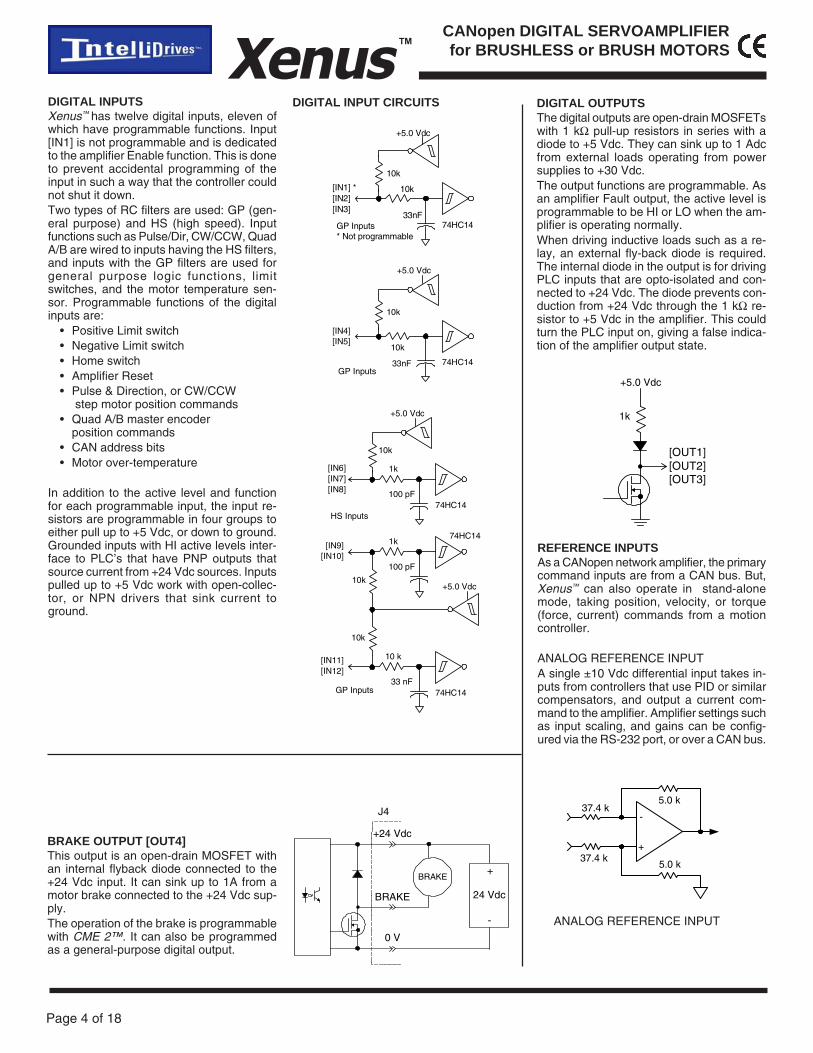
REFERENCE INPUTSAs a CANopen network amplifier, the primarycommand inputs are from a CAN bus. But,Xenus™ can also operate in stand-alonemode, taking position, velocity, or torque(force, current) commands from a motioncontroller.
ANALOG REFERENCE INPUTA single ±10 Vdc differential input takes in-puts from controllers that use PID or similarcompensators, and output a current com-mand to the amplifier. Amplifier settings suchas input scaling, and gains can be config-ured via the RS-232 port, or over a CAN bus.
DIGITAL OUTPUTSThe digital outputs are open-drain MOSFETswith 1 kΩ pull-up resistors in series with adiode to +5 Vdc. They can sink up to 1 Adcfrom external loads operating from powersupplies to +30 Vdc.The output functions are programmable. Asan amplifier Fault output, the active level isprogrammable to be HI or LO when the am-plifier is operating normally.When driving inductive loads such as a re-lay, an external fly-back diode is required.The internal diode in the output is for drivingPLC inputs that are opto-isolated and con-nected to +24 Vdc. The diode prevents con-duction from +24 Vdc through the 1 kΩ re-sistor to +5 Vdc in the amplifier. This couldturn the PLC input on, giving a false indica-tion of the amplifier output state.
DIGITAL INPUTSXenus™ has twelve digital inputs, eleven ofwhich have programmable functions. Input[IN1] is not programmable and is dedicatedto the amplifier Enable function. This is doneto prevent accidental programming of theinput in such a way that the controller couldnot shut it down.Two types of RC filters are used: GP (gen-eral purpose) and HS (high speed). Inputfunctions such as Pulse/Dir, CW/CCW, QuadA/B are wired to inputs having the HS filters,and inputs with the GP filters are used forgeneral purpose logic functions, limitswitches, and the motor temperature sen-sor. Programmable functions of the digitalinputs are:
• Positive Limit switch• Negative Limit switch• Home switch• Amplifier Reset• Pulse & Direction, or CW/CCW
step motor position commands• Quad A/B master encoder
position commands• CAN address bits• Motor over-temperature
In addition to the active level and functionfor each programmable input, the input re-sistors are programmable in four groups toeither pull up to +5 Vdc, or down to ground.Grounded inputs with HI active levels inter-face to PLC’s that have PNP outputs thatsource current from +24 Vdc sources. Inputspulled up to +5 Vdc work with open-collec-tor, or NPN drivers that sink current toground.
BRAKE OUTPUT [OUT4]This output is an open-drain MOSFET withan internal flyback diode connected to the+24 Vdc input. It can sink up to 1A from amotor brake connected to the +24 Vdc sup-ply.The operation of the brake is programmablewith CME 2™. It can also be programmedas a general-purpose digital output.
0 V
BRAKE
+24 Vdc
BRAKE
24 Vdc
+
-
J4 -
+
37.4 k
37.4 k
5.0 k
5.0 k
ANALOG REFERENCE INPUT
33nF
10k
10k
74HC14
[IN1] *[IN2][IN3]
GP Inputs* Not programmable
+5.0 Vdc
33nF
10k
10k
74HC14
[IN4][IN5]
GP Inputs
+5.0 Vdc
DIGITAL INPUT CIRCUITS
+5.0 Vdc
[OUT1][OUT2][OUT3]
1k
100 pF
1k
10k
74HC14
[IN6][IN7][IN8]
HS Inputs
+5.0 Vdc
100 pF
1k74HC14
[IN9][IN10]
10k
33 nF
10 k
74HC14
[IN11][IN12]
10k
+5.0 Vdc
GP Inputs

Page 5 of 18
CANopen DIGITAL SERVOAMPLIFIERfor BRUSHLESS or BRUSH MOTORSXenus ™
DIGITAL REFERENCE INPUTSIn stand-alone mode, digital reference inputs control amplifier current or velocity in thesame fashion as the analog reference input, but do it using digital signals.Digital inputs [IN9] and [IN10] have high-speed input filters and can be programmed forsignals in several formats.Current (torque, force) or velocity commands can be in one or two-wire format. In the one-wire format (50% PWM), a single input takes a square waveform that has a 50% duty cyclewhen the amplifier output should be zero. Thereafter, increasing the duty cycle toward100% will command a maximum positive output, and decreasing the duty cycle toward 0%will produce a maximum negative output.In two-wire format (PWM/Direction), one input takes a PWM waveform of fixed frequencyand variable duty cycle, and the other input takes a DC level that controls the polarity of theoutput current. A 0% duty cycle will command zero current, and a 100% will produce amaximum. The direction of the force or torque produced will depend on the polarity of theDC signal on the direction input. In either mode, inputs are programmable to treat 0% or100% inputs as faults as a safety measure should a cable break.
Current
Polarity
[IN9]
[IN10]
Duty = 0% to 100%
Current
Not used
[IN9]
[IN10]
Duty = 50% ±50%
<no connection>
MOTOR CONNECTIONSThere are five types of motor connections: Phase, digital Halls, analog encoder, digitalencoder, and temperature sensor. The phase connections carry the amplifier output cur-rents that drive the motor to produce force or torque. The digital Hall signals give absoluteposition feedback in six steps per electrical cycle. Analog encoder inputs work with encod-ers that output 1.0 Vpeak-peak analog Sin/Cos signals. Digital encoders are A/B quadra-ture types plus an index. Both types of encoders give incremental position feedback andare used for velocity and position modes. Finally, a motor temperature sensor providesmotor protection by signalling the amplifier to shut-down if the motor is overheating.
DIGITAL ENCODER SIGNALSThe motor encoder interface is a differentialline-receiver with R-C filtering on the inputs.The circuit is shown below. Encoders withdifferential outputs are required because theyare less susceptible to noise that can bedegrade single-ended outputs. Encodercables should use twisted-pairs for each sig-nal pair: A & /A, B & /B, Index & /Index. Anoverall shield should be used, and for longercables, shields for individual pairs may benecessary to guarantee signal integrity.The encoder signals are made available tothe controller via the signal connector J7,where they are re-transmitted by differentialline-drivers. This eliminates split cables thatwould have to route the motor encoder sig-nals to both amplifier and controller, as wellas providing a good signal quality termina-tion of the encoder signals at the amplifier.
DIGITALENCODER
-
+1k
1k
22 pF
22 pF
26LS32
/A, /B, /X
A, B, X
120
DIGITAL HALL SIGNALSHall signals are single-ended signals thatprovide absolute feedback within one elec-trical cycle of the motor. There are three ofthem (U, V, & W) and they may be sourcedby magnetic sensors in the motor, or by en-coders that have Hall tracks as part of theencoder disc. They typically operate at muchlower frequencies than the motor encodersignals, and in Xenus™ they are used forcommutation-initialization after startup, andfor checking the motor phasing after theamplifer has switched to sinusoidal commu-tation.
HALL U, V, W 10 k
3.3 nF
74HC14
+5 Vdc
10 k
UV
W
PWM/Direction Format 50% PWM Format
Motor HALL Inputs
Note: Active level of PWM inputs is programmable
ANALOG ENCODER SIGNALSXenus™ supports analog encoder signals forposition feedback.The Sin and Cos inputsare differential with 121 Ω terminating resis-tors and accept 1.0 Vp-p signals in the A/Bformat used by encoders with analog out-puts such as Heidenhain, Stegman, andRenishaw.
Sin(+)
120
120
ANALOGENCODER
-
+
-
+Cos(+)
Cos(-)
Sin
Cos
Sin(-)

Page 6 of 18
Xenus™CANopen DIGITAL SERVOAMPLIFIERfor BRUSHLESS or BRUSH MOTORS
+24VDC
LOGIC&
SIGNALPOWER
RTN
PWMINVERTER
L1
CONTROLLOGIC
MAINSL3
SIGNAL GND
+5 Vdc
U
V
W
MOTOR
HALLS
ENCODER
CASE
ISOLATION BARRIER
+5 Vdc
DC BUSS(+)
DC BUSS(-)
L2
AMPLIFIERCHASSIS
CONTROLSYSTEM
ENABLE [IN1]
SIGNAL GND
SIGNAL GND
SHIELD
J8J7
J1
J2
FRAME(SAFETY)GROUND
CONTROLSIGNAL
GROUND
~
~ -
+
~+
REGEN(-) REGEN(+)
SHIELD
BRAKE
+24 Vdc
+24 VdcGROUND
J3
J4
1760 µF
DC/DCCntrl
DC/DCConverter
+5 Vdc @250mA
PWMSTAGE
CONTROLPOWER
+5 Vdc
BRAKE
Chassis ground
GROUNDING A grounding system has three primary func-tions: safety, voltage-reference, and shield-ing. As a safety measure, the primary groundat J1-3 will carry fault-currents from the mainsin the case of an internal failure or short-cir-cuit of electronic components. Wiring to thisis typically done with the green conductorwith yellow stripe using the same gauge wireas that used for the mains. The pin on theamplifier at J1-3 is longer than the other pinson J1 giving it a first-make, last-break actionso that the amplifier chassis is never un-grounded when the mains power is con-nected. This wire is a ‘bonding’ conductorthat should connect to an earthed ground
point and must not pass through any circuitinterrupting devices. All of the other circuitson J1, J2, and J3 are mains-connected andmust never be grounded. The ground termi-nals at J1-3, J2-1, and J3-1 all connect tothe amplifier chassis and are isolated fromall amplifier internal circuits.Signal grounding references the amplifiercontrol circuits to those of the control sys-tem. These controls circuits typically havetheir own earth connection at some point.To eliminate ground-loops it is recommendedthat the amplifier signal ground be connectedto the control system circuit ground. Whenthis is done the amplifier signal voltages willbe referenced to the same 0 V level as thecircuits in the control system. Small currentsflow between controller and amplifier wheninputs and outputs interract. The signalground is the path for these currents to re-turn to their power sources in both controllerand amplifier.Shields on cables reduce emissions fromthe amplifier for CE compliance and protectinternal circuits from interference due to ex-ternal sources of electrical noise. Becauseof their smaller wire gauge, these should notbe used as part of a safety-ground system.Motor cases can be safety-grounded eitherat the motor, by earthing the frame, or by agrounding conductor in the motor cable thatconnects to J2-1. This cable should be ofthe same gauge as the other motor phasecables.For CE compliance and operator safety, theamplifier should be earthed by using exter-nal tooth lockwashers under the mountingscrews. These will make contact with the alu-minum chassis through the anodized finishto connect the chassis to the equipmentframe ground.
AMPLIFIER POWER SOURCESAn external +24 Vdc power supply is re-quired, and powers an internal DC/DC con-verter that supplies all the control voltagesfor amplifier operation. Use of an externalsupply enables CAN communication with theamplifier when the mains power has beenremoved.Power distribution in Xenus™ is divided intothree sections: +24 Vdc, signal, and high-voltage. Each is isolated from the other andall are isolated from the chassis.EXTERNAL +24 VdcThe primary side of the DC/DC converteroperates directly from the external +24 Vdcsupply and is isolated from other amplifierpower sections. The Brake output [OUT4]operates in this section and is referenced tothe +24 Vdc return (0V). It sinks current froman external load connected to the external+24 Vdc power source.INTERNAL SIGNAL POWERThe signal power section supplies power forthe DSP controller as well as logic inputs andoutputs. Motor feedback signals such asHalls, encoder, and temperature sensor op-erate from this power source. All signal cir-cuits are referenced to signal ground. Thisground should connect to the control sys-tem circuit ground or common so that ampli-fier and controller inputs and output voltagelevels work properly with each other.
MAINS POWERMains power drives the high-voltage section.It is rectified and capacitor-filtered to produce+HV, the DC ‘link’ power that drives the PWMinverter where is converted into the voltagesthat drives a three phase brushless, or DCbrush motor. An internal solid-state switchtogether with an external power resistor pro-vides dissipation during regeneration whenthe mechanical energy of the motor is con-verted back into electrical energy that mustbe dissipated before it charges the internalcapacitors to an overvoltage condition. Allthe circuits in this section are “hot”, that is,they connect directly to the mains and mustbe considered high-voltages and a shockhazard requiring proper insulation techniquesduring installation.
REGENERATIONThe chart below shows the energy absorp-tion in W·s for a Xenus™ amplifier operatingat some typical mains voltages. When theload mechanical energy is greater than thesevalues an external resistor is available as anaccessory.

Page 7 of 18
CANopen DIGITAL SERVOAMPLIFIERfor BRUSHLESS or BRUSH MOTORSXenus ™
DANGER: HIGH VOLTAGECIRCUITS ON J1, J2, & J3ARE CONNECTED TOMAINS POWER
14Motemp [IN5]
10
3
13Hall W
12Hall V
9
8
7
6
5
15
DIGITALHALLS
U
V
W
DIGITALENCODER
B
/B
+5 &
Gnd
for Encoder +
Hall
6
5
4
9
8
3
11
2
3
10
1-HV
J8
21
20
19
16
18
17
1
4
20
1
/A
A
11Hall U
Enc A
Enc /A
Enc B
Enc /B
Enc X
Enc /X
22
2
25
+5 Vdc @ 250 mA
Signal Ground
Ref(-)
BufferedEncoderOutputs
A
/A
B
/B
X
/X
Frame Ground
+24V
BRAKE
RTN J4
Earth
Fuse
J1
4L3
1∅
3∅
AC MAINS:100 to 240 Vac1Ø or 3Ø47 to 63 Hz
H
*
5
2
1
J3REGEN
REGEN
Frame Ground
4
3
J2
U
V
W
BRUSHLESSMOTOR
Fuse
Fuse
4
3
2
1
Mot U
Mot V
Mot W
Frame Ground
3
L2 N*2
1L1
* L3
L2
L1
[IN7] HS
[IN8] HS
[IN9] HS
[IN10] HS
7
[IN1] Enable
[IN4] GP
[IN2] GP
[IN3] GP
24 Ref(+) J7±10 VdcAnalog
Reference
[IN6] HS
26 [IN12] GP
12 [IN11] GP
14 [OUT2]
13 [OUT1]
15 [OUT3]
2Gnd
Gnd
16
17
18
19
Sin(+)
Sin(-)
Cos(+)
Cos(-)
+5 Vdc@ 250 mA
BRAKE
X
/X
Sin(+)
Sin(-)
Cos(+)
Cos(-)
+24 Vdc0.5 Adc
+
-
LIN
EF
ILT
ER
ANALOGENCODER
Fuse
Fuse
Control Power SupplyRequired for
Amplifier Operation
Amplifier mounting screw
Notes:1. The total output current from the +5 Vdc supply to J7-22 and J8-3 cannot exceed 250 mAdc.
Page 8 of 18
Xenus™CANopen DIGITAL SERVOAMPLIFIERfor BRUSHLESS or BRUSH MOTORS
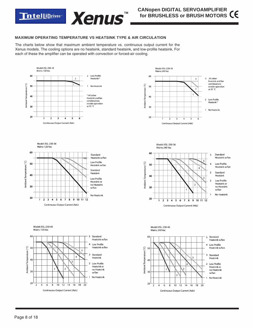
MAXIMUM OPERATING TEMPERATURE VS HEATSINK TYPE & AIR CIRCULATION
The charts below show that maximum ambient temperature vs. continuous output current for theXenus models. The cooling options are no heatsink, standard heatsink, and low-profile heatsink. Foreach of these the amplifier can be operated with convection or forced-air cooling.

Page 9 of 18
CANopen DIGITAL SERVOAMPLIFIERfor BRUSHLESS or BRUSH MOTORSXenus ™
4.25 inFan
4.25 inFan
4.25 inFan
HEATSINK & FAN CONFIGURATIONS
NO HEATSINKNO FAN
NO HEATSINKWITH FAN
LOW-PROFILEHEATSINKNO FAN
LOW PROFILE HEATSINKWITH FAN
STANDARDHEATSINKNO FAN
STANDARD HEATSINKWITH FAN
HEATSINK MOUNTING
Phase change material (PSM) is used in place of ther-mal grease. This material comes in sheet form andchanges from solid to liquid form as the amplifierwarms up. This forms an excellent thermal path fromamplifier heatplate to heatsink for optimum heat trans-fer.
STEPS TO INSTALL
1. Remove the PSM (Phase Change Material) fromthe clear plastic carrier.
2. Place the PSM on the amplifier taking care to cen-ter the PSM holes over the heatsink mounting holes.
3. Mount the heatsink onto the amplifier taking care tosee that the holes in the heatsink, PSM, and ampli-fier all line up.
4. Torque the #6-32 mounting screws to 8~10 lb-in(0.9~1.13 N·m).
Heatsink
#6-32 Mounting Screws
Phase Change Material
Xenus Amplifier
Transparent Carrier(Discard)
Page 10 of 18
Xenus™CANopen DIGITAL SERVOAMPLIFIERfor BRUSHLESS or BRUSH MOTORS
langiS niP
3LtupnIsniaM 4
dnuorGevitcetorP 3
2LtupnIsniaM 2
1LtupnIsniaM 1
J1 Mains Connections
langiS niP
UesahProtoM 4
VesahProtoM 3
WesahProtoM 2
dleihSelbaC 1
J2 Motor Outputs
langiS niP
rotsiseRnegeR 5
noitcennoCoN 4
rotsiseRnegeR 3
noitcennoCoN 2
dleihSelbaC 1
J3 Regen Resistor
langiS niP
rewoPlortnoCcdV42+ 3
tuptuOekarB 2
)nruteRcdV42+(V0 1
J4 +24 VDC & Brake
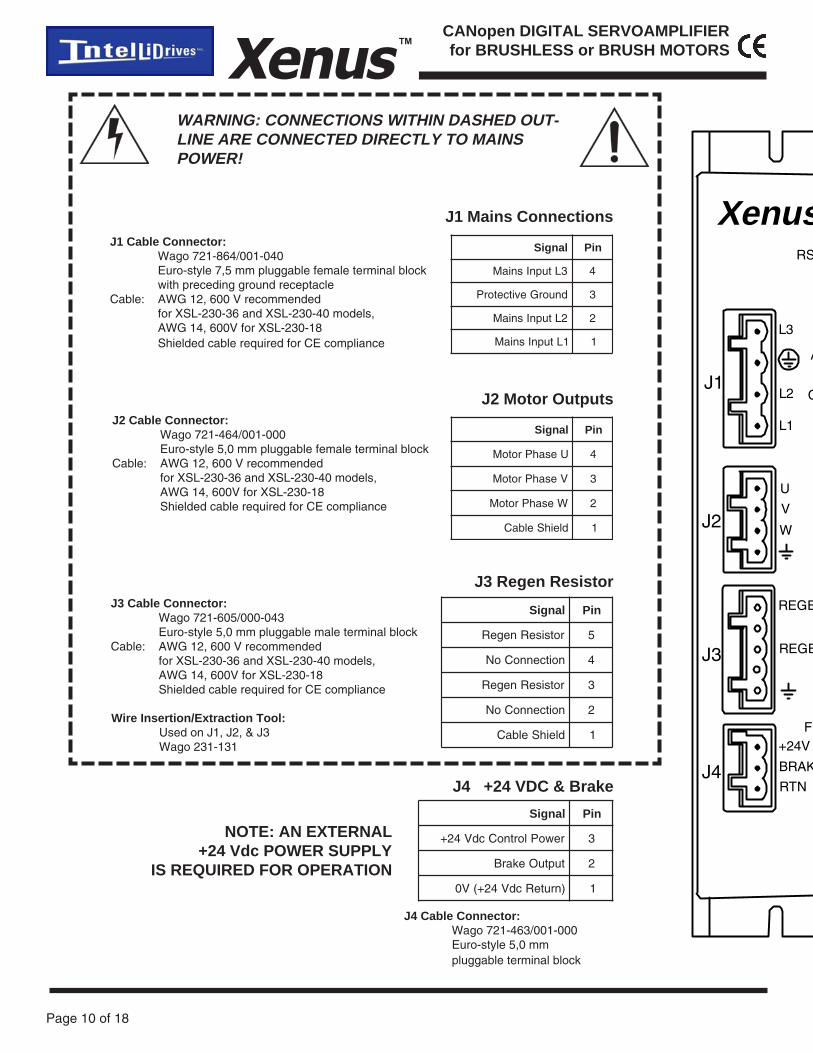
J1 Cable Connector:Wago 721-864/001-040Euro-style 7,5 mm pluggable female terminal blockwith preceding ground receptacle
Cable: AWG 12, 600 V recommendedfor XSL-230-36 and XSL-230-40 models,AWG 14, 600V for XSL-230-18Shielded cable required for CE compliance
J2 Cable Connector:Wago 721-464/001-000Euro-style 5,0 mm pluggable female terminal block
Cable: AWG 12, 600 V recommendedfor XSL-230-36 and XSL-230-40 models,AWG 14, 600V for XSL-230-18Shielded cable required for CE compliance
J3 Cable Connector:Wago 721-605/000-043Euro-style 5,0 mm pluggable male terminal block
Cable: AWG 12, 600 V recommendedfor XSL-230-36 and XSL-230-40 models,AWG 14, 600V for XSL-230-18Shielded cable required for CE compliance
J4 Cable Connector:Wago 721-463/001-000Euro-style 5,0 mmpluggable terminal block
WARNING: CONNECTIONS WITHIN DASHED OUT-LINE ARE CONNECTED DIRECTLY TO MAINSPOWER!
J4
J3
J2
J1
RS
A
FD+24V
BRAK
RTN
REGE
U
V
W
L1
L2
L3
C
Xenus
REGE
Wire Insertion/Extraction Tool:Used on J1, J2, & J3Wago 231-131
NOTE: AN EXTERNAL+24 Vdc POWER SUPPLY
IS REQUIRED FOR OPERATION
Page 11 of 18
CANopen DIGITAL SERVOAMPLIFIERfor BRUSHLESS or BRUSH MOTORSXenus ™
langiS niP langiS
dnuorGemarF 1 11 UllaHlatigiD
dnuorGlangiS 2 21 VllaHlatigiD
Am052@cdV5+ 3 31 WllaHlatigiD
AredocnE tupnI 4 41 rosneSpmeT]5NI[
A/redocnE tupnI 5 51 dnuorGlangiS
BredocnE tupnI 6 61 tupnI)+(niSredocnE
B/redocnE tupnI 7 71 tupnI)-(niSredocnE
XredocnE tupnI 8 81 tupnI)+(soCredocnE
X/redocnE tupnI 9 91 tupnI)-(soCredocnE
dnuorGlangiS 01 02 dnuorGlangiS
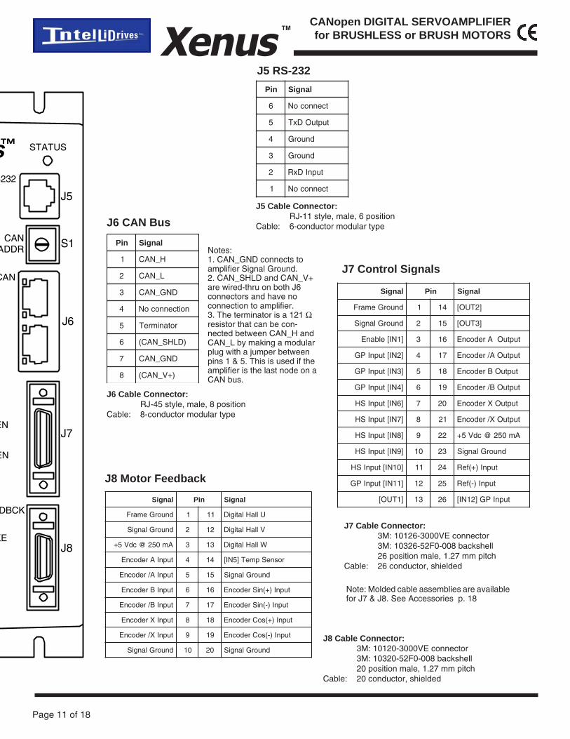
J8 Motor Feedback
langiS niP langiS
dnuorGemarF 1 41 ]2TUO[
dnuorGlangiS 2 51 ]3TUO[
]1NI[elbanE 3 61 tuptuOAredocnE
]2NI[tupnIPG 4 71 tuptuOA/redocnE
]3NI[tupnIPG 5 81 tuptuOBredocnE
]4NI[tupnIPG 6 91 tuptuOB/redocnE
]6NI[tupnISH 7 02 tuptuOXredocnE
]7NI[tupnISH 8 12 tuptuOX/redocnE
]8NI[tupnISH 9 22 Am052@cdV5+
]9NI[tupnISH 01 32 dnuorGlangiS
]01NI[tupnISH 11 42 tupnI)+(feR
]11NI[tupnIPG 21 52 tupnI)-(feR
]1TUO[ 31 62 tupnIPG]21NI[
J7 Control Signals
niP langiS
1 H_NAC
2 L_NAC
3 DNG_NAC
4 noitcennocoN
5 rotanimreT
6 )DLHS_NAC(
7 DNG_NAC
8 )+V_NAC(
J6 CAN Bus
niP langiS
6 tcennocoN
5 tuptuODxT
4 dnuorG
3 dnuorG
2 tupnIDxR
1 tcennocoN
J5 RS-232
J5 Cable Connector:RJ-11 style, male, 6 position
Cable: 6-conductor modular type
J6 Cable Connector:RJ-45 style, male, 8 position
Cable: 8-conductor modular type
J7 Cable Connector:3M: 10126-3000VE connector3M: 10326-52F0-008 backshell26 position male, 1.27 mm pitch
Cable: 26 conductor, shielded
J8 Cable Connector:3M: 10120-3000VE connector3M: 10320-52F0-008 backshell20 position male, 1.27 mm pitch
Cable: 20 conductor, shielded
Note: Molded cable assemblies are availablefor J7 & J8. See Accessories p. 18
Notes:1. CAN_GND connects toamplifier Signal Ground.2. CAN_SHLD and CAN_V+are wired-thru on both J6connectors and have noconnection to amplifier.3. The terminator is a 121 Ωresistor that can be con-nected between CAN_H andCAN_L by making a modularplug with a jumper betweenpins 1 & 5. This is used if theamplifier is the last node on aCAN bus.
STATUS
S232
CANADDR
J5
S1
J6
J7
J8
DBCK
KE
EN
CAN
s™
EN

Page 12 of 18
Xenus™CANopen DIGITAL SERVOAMPLIFIERfor BRUSHLESS or BRUSH MOTORS
ACCESSORY CABLE CONNECTIONS
110
1120
Amplifier J8
113
1426
Amplifier J7
FEEDBACK CABLE ( XSL-FC-10 )
SIGNAL CABLE ( XSL-CC-10 )
langiS niP )epirtS/ydoB(roloC riaP )epirtS/ydoB(roloC niP langiS
dleihS 1 naT/etihW a1 a8 teloiV/etihW 41 ]2TUO[
dnuorGlangiS 2 etihW/naT b1 b8 etihW/teloiV 51 ]3TUO[
]1NI[elbanE 3 nworB/etihW a2 a9 yarG/etihW 61 tuptuOAredocnE
]2NI[tupnIPG 4 etihW/nworB b2 b9 etihW/yarG 71 tuptuOA/redocnE
]3NI[tupnIPG 5 kniP/etihW a3 a01 nworB/naT 81 tuptuOBredocnE
]4NI[tupnIPG 6 etihW/kniP b3 b01 naT/nworB 91 tuptuOB/redocnE
]6NI[tupnISH 7 egnarO/etihW a4 a11 kniP/naT 02 tuptuOXredocnE
]7NI[tupnISH 8 etihW/egnarO b4 b11 naT/kniP 12 tuptuOX/redocnE
]8NI[tupnISH 9 wolleY/etihW a5 a21 egnarO/naT 22 Am052@cdV5+
]9NI[tupnISH 01 etihW/wolleY b5 b21 naT/egnarO 32 dnuorGlangiS
]01NI[tupnISH 11 neerG/etihW a6 a31 wolleY/naT 42 )+(nIfeRgolanA
]11NI[tupnIPG 21 etihW/neerG b6 b31 naT/wolleY 52 )-(nIfeRgolanA
]1TUO[ 31 eulB/etihW a7 b7 etihW/eulB 62 ]21NI[ tupnIPG
langiS niP )epirtS/ydoB(roloC riaP )epirtS/ydoB(roloC niP langiS
dnuorGemarF 1 naT/etihW a1 b1 etihW/naT 11 UllaHlatigiD
dnuorGlangiS 2 nworB/etihW a2 a7 eulB/etihW 21 VllaHlatigiD
Am052@cdV5+ 3 etihW/nworB b2 b7 etihW/eulB 31 WllaHlatigiD
tupnIAtredocnE 4 kniP/etihW a3 a8 teloiV/etihW 41 rosneSpmeT]5NI[
tupnIA/tredocnE 5 etihW/kniP b3 b8 etihW/teloiV 51 dnuorGlangiS
tupnIBredocnE 6 egnarO/etihW a4 a9 yarG/etihW 61 tupnI)+(niSredocnE
tupnIB/tredocnE 7 etihW/egnarO b4 b9 etihW/yarG 71 tupnI)-(niSredocnE
tupnIXredocnE 8 wolleY/etihW a5 a01 nworB/naT 81 tupnI)+(soCredocnE
tupnIX/redocnE 9 etihW/wolleY b5 b01 naT/nworB 91 tupnI)-(soCredocnE
dnuorGlangiS 01 neerG/etihW a6 b6 etihW/neerG 02 dnuorGlangiS
Plug assembly: Molex 52316-2611Boot cover: Molex 52370-2610Molded connector mates with amplifier J7 and has flying-lead terminations with colors shown in chart below.
Note: Wires are solid-color with astripe of an alternate color.E.g. “Black / Orange” is a black wirewith an orange stripe.
Plug assembly: Molex 52316-2011Boot cover: Molex 52370-2010Molded connector mates with amplifier J8 and has flying-lead terminations with colors shown in chart below.

Page 13 of 18
CANopen DIGITAL SERVOAMPLIFIERfor BRUSHLESS or BRUSH MOTORSXenus ™
Weights:Amplifier: 3.0 lb (1.36 kg)Small Heatsink: 1.31 lb (0.59 kg)Large Heatsink: 1.84 lb (0.83 kg)
Inches (mm)
DIMENSIONS
7.55(191,7)
3.00(76,2)
1.5(38,1)
8 x0.160(4,1)
7.15(181,6)
1.00(25,4)
0.88(22,4)
5.54(140,7)
LOW-PROFILEHEATSINK OPTION (-HL)
6.75(171,5
)
2.55(64,8)
1.99(50,5)
STANDARDHEATSINK OPTION (-HS)
0.925(23,5)
Note:Use external tooth lockwashers betweenmounting screw head and amplifier chas-sis for safety and CE compliance.Recommended screws are #6-32 (M3.5)torqued to 8~10 lb·in (0.79~1.02 N·m).
Page 14 of 18
Xenus™CANopen DIGITAL SERVOAMPLIFIERfor BRUSHLESS or BRUSH MOTORS
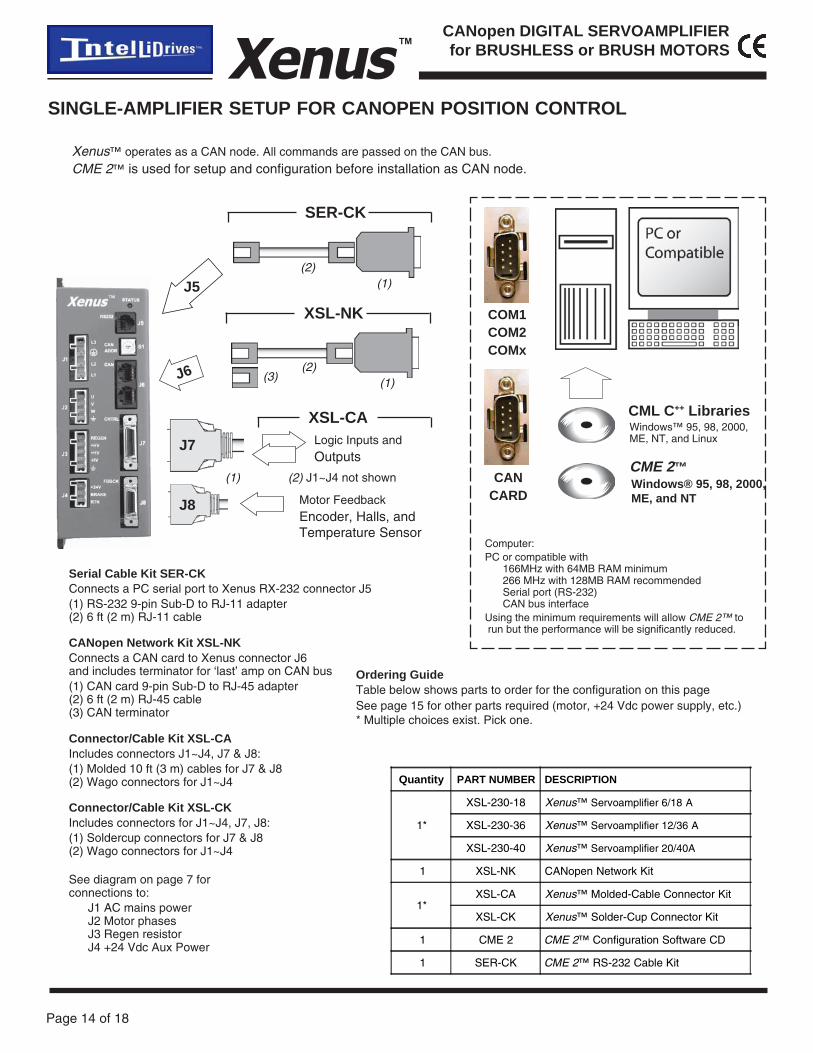
SINGLE-AMPLIFIER SETUP FOR CANOPEN POSITION CONTROL
XSL-NK
CML C++ Libraries
CANCARD
See diagram on page 7 forconnections to:
J1 AC mains powerJ2 Motor phasesJ3 Regen resistorJ4 +24 Vdc Aux Power
J6
CANopen Network Kit XSL-NKConnects a CAN card to Xenus connector J6and includes terminator for ‘last’ amp on CAN bus(1) CAN card 9-pin Sub-D to RJ-45 adapter(2) 6 ft (2 m) RJ-45 cable(3) CAN terminator
Connector/Cable Kit XSL-CAIncludes connectors J1~J4, J7 & J8:(1) Molded 10 ft (3 m) cables for J7 & J8(2) Wago connectors for J1~J4
J8
J7
XSL-CALogic Inputs andOutputs
Motor FeedbackEncoder, Halls, andTemperature Sensor
Xenus™ operates as a CAN node. All commands are passed on the CAN bus.
CME 2™ is used for setup and configuration before installation as CAN node.
Quantity PART NUMBER DESCRIPTION
1*
XSL-230-18 Xenus™ Servoamplifier 6/18 A
XSL-230-36 Xenus™ Servoamplifier 12/36 A
XSL-230-40 Xenus™ Servoamplifier 20/40A
1 XSL-NK CANopen Network Kit
1*XSL-CA Xenus™ Molded-Cable Connector Kit
XSL-CK Xenus™ Solder-Cup Connector Kit
1 CME 2 CME 2™ Configuration Software CD
1 SER-CK CME 2™ RS-232 Cable Kit
COM1COM2COMx
SER-CK
J5
Serial Cable Kit SER-CKConnects a PC serial port to Xenus RX-232 connector J5(1) RS-232 9-pin Sub-D to RJ-11 adapter(2) 6 ft (2 m) RJ-11 cable
Ordering GuideTable below shows parts to order for the configuration on this pageSee page 15 for other parts required (motor, +24 Vdc power supply, etc.)* Multiple choices exist. Pick one.
(1)(2)
Connector/Cable Kit XSL-CKIncludes connectors for J1~J4, J7, J8:(1) Soldercup connectors for J7 & J8(2) Wago connectors for J1~J4
(1)(2)
(3)
(1) (2) J1~J4 not shownCME 2™
Windows™ 95, 98, 2000,ME, NT, and Linux
Windows® 95, 98, 2000,ME, and NT
Computer:PC or compatible with
166MHz with 64MB RAM minimum266 MHz with 128MB RAM recommendedSerial port (RS-232)CAN bus interface
Using the minimum requirements will allow CME 2™ to run but the performance will be significantly reduced.

Page 15 of 18
CANopen DIGITAL SERVOAMPLIFIERfor BRUSHLESS or BRUSH MOTORSXenus ™
XSL-NK
J6
CAN Terminator(Part of XSL-NK)
J6
J6
XSL-NC-10orXSL-NC-01
XSL-NC-10orXSL-NC-01
MULTIPLE-AMPLIFIER SETUP FOR CANOPEN POSITION CONTROL
For multiple-amplierinstallations, use the orderingguide on this page. Computerequipment is the same as forsingle-amplifier installations.And Serial Cable Kit SER-CKis used when CME 2™ is inuse for amplifier set up andconfiguration.
Ordering GuideTable below shows parts to order for the configuration on this pageSee page 15 for other parts required (motor, +24V power supply, etc.)For “n” in the Quantity column, substitute the number of amplifiersused.* Multiple choices exist. Pick one.
For side-by-side amplifiermounting, use XSL-NC-01cables that are 1 ft long.Use XSL-NC-10 cables(length is 10 ft) wheredistances betweenamplifiers is greater.
SER-CK
REBMUNTRAP NOITPIRCSED
81-032-LSX suneX ™ vreS 81/6reifilpmao A
63-032-LSX suneX ™ vreS 63/21reifilpmao A
04-032-LSX suneX ™ vreS A04/02reifilpmao
KN-LSX tiKkrowteNnepoNAC
01-CN-LSX )m3(tf01,elbackrowtenNAC
10-CN-LSX )m3.0(tf1,elbackrowtenNAC
KC-LSX suneX tiKrotcennoCpuC-redloS™
AC-LSX suneX tiKrotcennoCelbaC-dedloM™
2EMC 2EMC DCerawtfoSnoitarugifnoC™
KC-RES 2EMC tiKelbaC232-SR™
SH-LSX )lanoitpO(dradnatS,knistaeH
LH-LSX )lanoitpO(eliforPwoL,knistaeH
10-AR-LSX 03,rotsiseRnoitarenegeR Ω )lanoitpO(
20-AR-LSX 51,rotsiseRnoitarenegeR Ω )lanoitpO(

Page 16 of 18
Xenus™CANopen DIGITAL SERVOAMPLIFIERfor BRUSHLESS or BRUSH MOTORS
SER-CK
J5
STAND-ALONE OPERATION
COM1COM2COMx
CME 2™Windows® 95, 98, 2000,ME, and NT
Computer:PC or compatible with
166MHz with 64MB RAM minimum266 MHz with 128MB RAM recommendedSerial port (RS-232)Motion controller card
Using the minimum requirements will allow CME 2™ to run but the performance will be significantly reduced.
Xenus™ takes digital position commands in Pulse/Direction, or CW/CCWformat from an external controller or quadrature encoder signalsfrom a master-encoder for electronic gearing .CME 2™ used for setup and configuration.
J8
J7
XSL-CA
Digital reference signals,Logic Inputs and Outputs
Motor FeedbackEncoder, Halls, andTemperature Sensor
MotionController
REBMUNTRAP NOITPIRCSED
81-032-LSX suneX ™ vreS 81/6reifilpmao A
63-032-LSX suneX ™ vreS 63/21reifilpmao A
04-032-LSX suneX ™ vreS A04/02reifilpmao
AC-LSX suneX tiKrotcennoCelbaC-dedloM™
KC-LSX suneX tiKrotcennoCpuC-redloS™
2EMC 2EMC DCerawtfoSnoitarugifnoC™
KC-RES 2EMC tiKelbaC232-SR™
SH-LSX )lanoitpO(dradnatS,knistaeH
LH-LSX )lanoitpO(eliforPwoL,knistaeH
10-AR-LSX 03,rotsiseRnoitarenegeR Ω )lanoitpO(
20-AR-LSX 51,rotsiseRnoitarenegeR Ω )lanoitpO(
Ordering GuideTable below shows parts to order for the configuration on this pageSee page 15 for other parts required (motor, +24 Vdc power supply, etc.)

Page 17 of 18
CANopen DIGITAL SERVOAMPLIFIERfor BRUSHLESS or BRUSH MOTORSXenus ™
PARTS USED IN ALL CONFIGURATIONS
AC LineFilter
Fuses
RegenResistor
XSL-RA-01XSL-RA-02
BrushlessServo Motor withDigital HallsDigital Encoder orAnalog EncoderThermal sensor (optional)
DC BrushServo MotorEncoder feedbackThermal sensor
+24 VdcPower Supply
Heat-sink
Each component is labeled Required, Optional, or CE.Required components are necessary for operation of Xenus in all cases.Optional components depend on the particular application.CE after Required indicates that these parts are necessary for CE compliance.
REQUIRED
Optional
Optional
Required, CERequired, CE
Required
Required
One motor is always required.It may be brushless or brush.
Page 18 of 18
Xenus™CANopen DIGITAL SERVOAMPLIFIERfor BRUSHLESS or BRUSH MOTORS
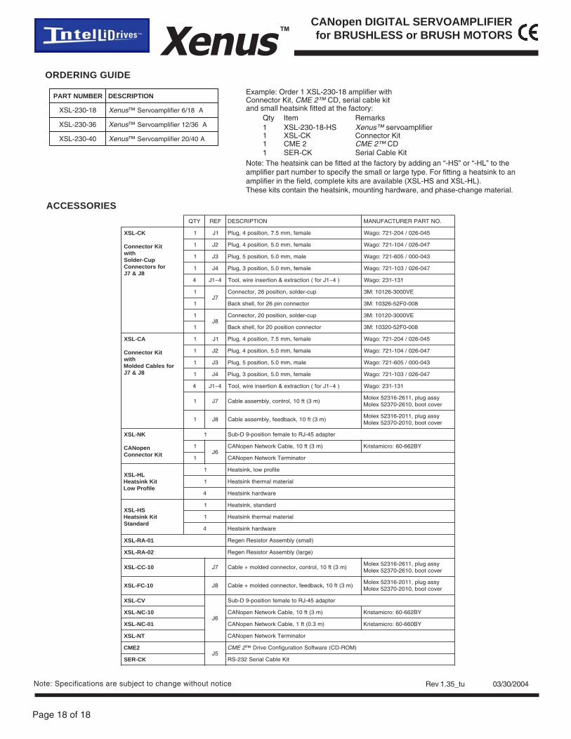
ORDERING GUIDE
Example: Order 1 XSL-230-18 amplifier withConnector Kit, CME 2™ CD, serial cable kitand small heatsink fitted at the factory:
Qty Item Remarks1 XSL-230-18-HS Xenus™ servoamplifier1 XSL-CK Connector Kit1 CME 2 CME 2™ CD1 SER-CK Serial Cable Kit
Note: The heatsink can be fitted at the factory by adding an “-HS” or “-HL” to theamplifier part number to specify the small or large type. For fitting a heatsink to anamplifier in the field, complete kits are available (XSL-HS and XSL-HL).These kits contain the heatsink, mounting hardware, and phase-change material.
ACCESSORIES
REBMUNTRAP NOITPIRCSED
81-032-LSX suneX ™ vreS 81/6reifilpmao A
63-032-LSX suneX ™ vreS 63/21reifilpmao A
04-032-LSX suneX ™ vreS 04/02reifilpmao A
Rev 1.35_tu 03/30/2004
YTQ FER NOITPIRCSED .ONTRAPRERUTCAFUNAM
KC-LSX
tiKrotcennoChtiw
puC-redloSrofsrotcennoC
8J&7J
1 1J elamef,mm5.7,noitisop4,gulP 540-620/402-127:ogaW
1 2J elamef,mm0.5,noitisop4,gulP 740-620/401-127:ogaW
1 3J elam,mm0.5,noitisop5,gulP 340-000/506-127:ogaW
1 4J elamef,mm0.5,noitisop3,gulP 740-620/301-127:ogaW
4 4~1J )4~1Jrof(noitcartxe&noitresnieriw,looT 131-132:ogaW
17J
puc-redlos,noitisop62,rotcennoC EV0003-62101:M3
1 rotcennocnip62rof,llehskcaB 800-0F25-62301:M3
18J
puc-redlos,noitisop02,rotcennoC EV0003-02101:M3
1 rotcennocnoitisop02rof,llehskcaB 800-0F25-02301:M3
AC-LSX
tiKrotcennoChtiw
rofselbaCdedloM8J&7J
1 1J elamef,mm5.7,noitisop4,gulP 540-620/402-127:ogaW
1 2J elamef,mm0.5,noitisop4,gulP 740-620/401-127:ogaW
1 3J elam,mm0.5,noitisop5,gulP 340-000/506-127:ogaW
1 4J elamef,mm0.5,noitisop3,gulP 740-620/301-127:ogaW
4 4~1J )4~1Jrof(noitcartxe&noitresnieriw,looT 131-132:ogaW
1 7J )m3(tf01,lortnoc,ylbmessaelbaCyssagulp,1162-61325xeloM
revoctoob,0162-07325xeloM
1 8J )m3(tf01,kcabdeef,ylbmessaelbaCyssagulp,1102-61325xeloM
revoctoob,0102-07325xeloM
KN-LSX
nepoNACtiKrotcennoC
1 retpada54-JRotelamefnoitisop-9D-buS
16J
)m3(tf01,elbaCkrowteNnepoNAC YB266-06:orcimatsirK
1 rotanimreTkrowteNnepoNAC
LH-LSXtiKknistaeH
eliforPwoL
1 eliforpwol,knistaeH
1 lairetamlamrehtknistaeH
4 erawdrahknistaeH
SH-LSXtiKknistaeH
dradnatS
1 dradnats,knistaeH
1 lairetamlamrehtknistaeH
4 erawdrahknistaeH
10-AR-LSX )llams(ylbmessArotsiseRnegeR
20-AR-LSX )egral(ylbmessArotsiseRnegeR
01-CC-LSX 7J )m3(tf01,lortnoc,rotcennocdedlom+elbaCyssagulp,1162-61325xeloM
revoctoob,0162-07325xeloM
01-CF-LSX 8J )m3(tf01,kcabdeef,rotcennocdedlom+elbaCyssagulp,1102-61325xeloM
revoctoob,0102-07325xeloM
VC-LSX
6J
retpada54-JRotelamefnoitisop-9D-buS
01-CN-LSX )m3(tf01,elbaCkrowteNnepoNAC YB266-06:orcimatsirK
10-CN-LSX )m3.0(tf1,elbaCkrowteNnepoNAC YB066-06:orcimatsirK
TN-LSX rotanimreTkrowteNnepoNAC
2EMC5J
2EMC )MOR-DC(erawtfoSnoitarugifnoCevirD™
KC-RES tiKelbaClaireS232-SR
Note: Specifications are subject to change without notice