Embed Size (px)
Citation preview

Vertical Load-BearingWall Panels
Technical Sheet and Installation Guide

Index
1 Technical Sheet1.1 Vertical Load Bearing Wall Panel
2 Design Considerations2.1 General considerations
3 Installation Guide3.1 General installation guidelines
3.2 Preparation
3.3 Wall Panel Installation
3.4 Panel Cutting
4 Renders and Finishes4.1 Products
2

3
1 Technical Sheet1.1 Vertical Load-BearingWall Panel
General Features
Hebel AAC (Autoclaved Aerated Concrete) Wall Panels are lightweight, fire resistant, fast and easy to install. Hebel AAC Vertical Load-Bearing Wall Panel is a reinforced (Grade 70 steel) element spanning a full story height. The Hebel Panel system is based on a standard two feet wide module. The thickness and panel length (height) vary depending on the design requirements and constraints of the project.
Uses
Hebel AAC Vertical Wall Panels are used to build load-bearing and non load-bearing exterior and interior walls for hotels, commercial and industrial buildings.
Dimensions[1][5] Length: Up to 20 ft.
[2][3] Thickness: 6, 7, 8, 10 and 12 in.[4] Width: 24 in.
[1] [2][4] [3] [5]Tolerance ± 3/16”, Tolerance ± 1/8”, Nominal, Height.
Manufactured according to ASTM C1452
Properties
CharacteristicHebel Wall Panel
AAC-6
Nominal Density
Design Waight [1]
Minimum Conpressive Strength (f’c)
Module of Elasticity
Drying Shrinkage
Thermal Expansion Coefficient
[1]Values consider material´s moisture content.
Table 1: Physical and design properties.
337 lb/ft
345 lb/ft
2870 lb/in
2377,000 lb/in
0.0024 in/ft
-68 x 10 1/°K
[1]Thickness
in
6
7
8
10
12
Designs WeightAAC-6
in*
5.906
6.889
7.874
9.843
11.811
2lb/ft
22.12
25.81
29.49
36.87
44.24
lb/ft**
44.27
51.65
59.03
73.78
88.54
in
3
3
3
4
4
GrooveDiam
[1] Nominal dimension, *Exact dimension, **2 ft. wide panel.
Table 2: Hebel wall panel design weight.
Hebel Wall PanelsAAC-6
0.9811 BTU- in/ 2ft h°F
Units: BTU = british thermal unit, 2 ft = square feet, h = hour, Fahrenheit.
in = inches,°F =
Table 3: Hebel wall panel Thermal Conductivity
Thermal Properties
Fire Performance
Material
Hebel Wall
Panel AAC-46 4 U920
Thickness
in
Fire Rating
Hour
UL DesignNumber
UL Fire ResistanceDirectory 1998
Note: Testing performed at Underwriters Laboratories, Inc.under ASTM E119 (UL/ANSI 263) “Fire Test of BuildingConstructions and Materials.
Table 4: Hebel wall panel fire rating.
Acoustic Performance
Hebel Wall Panel AAC-6
Hebel 8” Panel AAC-6/600 Unfinished
Note: Testing performed at Acoustic Systems, Inc., Austin. TX in accordance
with ASTM E 90 “Standard Method for Laboratory Measurement of Airbome
Soung Transmission Loss of Building Partitions”.
Table 5: Hebel wall panel acoustic performance.
50
STC
Fig. 1: Hebel wall panels packaging.
>_
Thermal Conductivity

4
The components listed herein represent a typical panel installation. However, other items might be needed during a Hebel Vertical Load-Bearing Wall Panel Installation. Due to design or installation requirements, lintel panels may be used in conjunction with or substituted by steel headers, precast concrete lintels or cast-in-place concrete. In situations where small in-fill is required, Hebel AAC Block may be specified. All Hebel components are identified on shop drawings for every project.
3.1 General Installation Guidelines
Before Installation of Hebel Wall Panels
Check foundation
– Foundation must be designed according to Local Building Codes. Verify the levelness of slab or foundation.
– Before concrete is poured, check foundation dimensions and wall vertical reinforcement (spacing) to comply with shop drawings. Ensure the pipes, drains and other utilities installations have been placed properly.
Clear the unloading and provisional storage area
– Unload panels using forklift, nylon straps, slings or pallet fork on a crane cable. Consult your OSHA safety manual for “rigging” or other safety considerations.
– Insure adherence to OSHA Guidelines - Leading Edge Subpart M (Fall Protection).
– Panels should always be stored away from other construction activities, and on a flat-grade area that is not susceptible to standing water, erosion or settling.
– Place panels over wood blocks (panels must not be in contact with ground) and keep the material covered and banded until ready for installation.
Check material and installation logistics
– Verify dimensions, positions and quantity of the panels according to shop drawings.
– Define sequence of panel installation.
– Define type of installation equipment (crane or similar).
– Evaluate quantity of personnel required.
2.1 General considerations
– The Hebel AAC Vertical Load-Bearing Wall Panel system includes the following components: Full height load-bearing wall panels (2 ft. wide), Jamb Panels (adjacent to a window, door or mechanical opening which supports a lintel panel), Lintels Panels (load bearing or non-load bearing panel over window or door openings) and Sill Panels (located below a window or mechanical opening) -see Fig. 2-.
– Hebel Wall Panels can be used as structural load-bearing and shear walls and shall be designed in compliance with safety and serviceability requirements as specified by ACI 318-95 and guidelines of ACI 523.2/R-96 and ACI 530-05.
– The design of Hebel Wall Panels should consider wind loads according to Local Building Codes.
Rebars
Sill Panel
CornerPanel
Fig. 2: Hebel wall panels system elements.
Hebel Lintel
Jamb Panel
Rebars
Full HeightPanel
Foundation
– Slenderness ratio must be revised as follows: Hebel wall in vertical arrangement: Panel slenderness ratio: l/t 30 where l = Panel length and t = Panel thickness.
– Vertical grooved joints between panels requires reinforcement according to structural design (5/8 in. rebars minimum).
– Fitting panels should not be less than 16 in. wide. If more than one fitting panel is required on a wall, at least two normal (non-fitting) panels shall be installed between them.
2 DesignConsiderations
3 InstallationGuide
<_

5
Lifting EquipmentHebel Lifting ClampType WKV (Manufactured by Van de Blij B.V.)
The WKV clamp is designed specifically for vertical and horizontal (lintels) installation of
3.2 Preparation
Shop Drawings
Shop Drawings include the following information: Wall panel layout, wall elevations, sections and details, general notes, revision date and number, panel schedule indicating panel number (see Fig. 3), quantity of panels and dimensional information (length, width and thickness). Review shop drawings and ensure that everyone is using the latest
Check for material, tools and equipment
Available for purchase from Xella– Hebel Thin-bed Mortar– Hebel Repair Mortar– Corrugated Nails– Hebel Nails (4” or 6”)– WKV Lifting Clamp[For Rent]– Helifix Anchors (8mm)– Mortar Trowel
Provided by the Contractor / Owner– Temporary Bracing– Crane and Accessories– Fine Grout Mortar.– Nails, threaded rod, nut, couples, washers, etc.– 6 ft. Carpenter’s Level– ½”Ø A370 Thru-bolts– Choker & Shackle– Mixing Tub / Paddles– Wood Guide Templates– Reinforcing Bars– Rebar Bender– Tape measure, chalk-line– Trubolt wedge anchors– Wakai Hit Nails [6 x 110 mm]
Table 6: WKV Lifting Clamp Specifications.
Clamp Type
Fixed Internal Height
Clamp Lenght
Clamp Range
Max. Load Bearing Capacity
Weight
[2]Pressure
WKV 15-20 WKV 20-25
260 mm
200 mm
6” to 8”
(15-20 cm)
8” to 10”
(20-25 cm)
1,540 lb (700 kg) 1,650 lb (750 kg)
220 lb (100 kg)
110 bar < Clamp Pressure < 140 bar
[1] Supplied stan dard with manometer to check clamp press ure.
[2] Clamp pressure must be within the acceptable range.
Concept[1]
Clamp
Specifications
Fig. 3: Hebel Wall Panel Identification.
Project Number5 Digits
Groove
Position Number (Item)See Panel schedule
Type / AreaV = Vertical Installation
Groove
HUD MR 1300b
P08V0282031
Hebel wall panels. The clamp has a constant clamp force lock (torque wrench principle).
Every day, before using the clamp, check the clamp pressure using the pressure cylinder (manometer) and record the reading in the log. Important: Each manometer is
dedicated to a specific lifting clamp type. Verify the lifting and manometer shipped has the same identification numbers. Test the lifting clamp pressure at least twice every day prior to start of panel installation (start of the day and at
the mid-day). The clamp pressure should be as follows:
110 bar < Clamp Pressure < 140 bar
If the pressure is either lower or higher than the values in the range, the clamp must be checked by an authorized service representative. If the manometer shows the correct pressure, you may use the clamp. Record the details in the log and keep the log with the manometer and the clamp. The pressure must be recorded in the log daily.
– Set delivery schedule to match the erection sequence. Excessive handling of AAC panels may damage the element.
– Chips and spalls can be repaired. If any panel reinforcing is visible, contact an autorized AAC representative.
– All damaged surface areas may be repaired using a compatible AAC patching compound.
– AAC panels that have surface or minor cracks are usable. Contact an authorized AAC representative when cracks extend completely through the panel.
version (see revision number). Drawings must be approved for construction in order to begin panel installation.
Panel Identification
Every panel can be easily identified by a reference number (project number) and panel information printed on one end-side of the panel. See panel schedule and drawings to corroborate dimensions and to determine its final position.
Fig. 4: Hebel load bearing wall panels.
Fig. 5: WKV Lifting Clamp and Manometer.

6
Template Layout
The purpose of the template is to establish a true and square plan within the building perimeter and to determine control points around the building in order to assess the accuracy of panel placement as installation progresses.
Suggested Material and Equipment (Included but not limited)
• 2” x 4” high grade lumber for use as a panel template guide.• Level or Transit-Level.• Masonry screws (Hilti KWIK-CON II or ITW Tapcon)• 2” x 4” wood cleats.• Chalk-line, tape measure, etc.• Metal square.
Note: All surfaces which are intendedto remain exposed at the completion ofthe project must be protected with feltpaper (30# min) to prevent staining frommortar droppings.
Template Installation
Fig. 6: Check the levelness of the slab prior to installing
the template.
Fig. 7: Trace building wall lines. Check alignment and square.Snap chalk-line on slab along the inside face of the wall panels.
Fig. 8: Place cleats every 4 ft. and perpendicular towall lines. (secure cleats with masonry screwsHilti, ITW Tapcon or similiar).
Fig. 9: Place template (elevated) on cleats to allowuniform distribution of mortar bed. Align templeateto building wall lines.
Fig. 10: Identify openings on tamplate.
Fig. 11: Indicate panel number, door & windowsopenings, mechanical opening, etc.

7
Temporary Bracing
The temporary bracing used for the installation of Hebel VerticalLoad Bearing Wall Panels may be accomplished is accordance with the following schedules:
_<Fig. 12: Bracing type spacification for wall height 12 ft.
Fig. 13: Bracing type spacification for wall height > 12 ft.
Note:
Temporary bracing shall remain in
place until shear key grouting (vertical
joints), floor or roof system and concrete
bond beams have been completed and
at least 24 hours old.
2/3 PANEL HEIGHT
1
1
E3
E2
E1
E1
E2
Table 9: Bracing type spacification for wall height > 12 ft.
Wall Height > 12’-0”See Fig. 13
Fasten top of Pipe-Bracing
@ 6 ft OC with (1) 1/2” Ø A307 Thru-Boilt
Use a 1/4”x5”x 5” plate washer on
the outside wall surface.
E4
Ele
me
nt
Schedule “A”
Fasten bottom of Pipe-Bracing to concrete slab with
(1) 1/2” Ø ITW Trubolt wedge anchor w/ (1) 2 1/4” embed.
Fasten to Hebel floor panels w/(1) 1/2” Ø A307 Thru-Bolt
Use a 1/4”x5”x5” plate washer on the bottom floor surface.
2”x4” lumber continuos with Hebel AAC nails @ 8 in.
Design Pipe-Bracing for
a Maximum Load = 700 lb
(Tension/Compression)
Design Pipe-Bracing for
a Maximum Load = 1000 lb
(Tension/Compression)
Temporary bracing shall remain in place until shear key grouting
(vertical joints), floor or roof system and concrete bond beams have
been completed and at least 24 hours old.
E5
E3
Schedule “B”
_<Wall Height 12’-0”
2”x4” - “T-Brace” with 10d
common nails @ 12 in OC and
installed @ 6 ft OC (walls &
openings < 6 ft wide). For
openings > 6 ft wide, provide
bracing @ each side.
See Fig. 12
2”x4” - “T-Brace” with 10d
common nails @ 12 in OC and
installed @ 4 ft OC (walls &
openings < 4 ft wide). For
openings > 4 ft wide, provide
bracing @ each side.
2”x4”x12” Cleat fasten to concrete slab with (2) 1/4” Ø x 3 1/4” tapcons.
Fasten to Hebel wall/floor panels with (3) 6x1 10
Wakai Hit nails or (2) Hebel AAC nails (4” or 6” long.)
(Note: Pre-drill 1/4” holes through wood cleats for
Wakai Hit nails or Hebel AAC Nails)
Fasten “T-Brace” to cleat with (3) 16d sommon nails.
2”x 4” lumber continuos with 12d common nails @ 5 in.or Hebel AAC nails @ 10 in.
Note: All bracing material shall be Southern Pine (construction grace).
Temporary bracing shall remain in place unitl shear key grouting
(vertical joints), floor or roof system and concrete bond beams have
been completed and at least 24 hours old.
Schedule “A” Schedule “B”
E1
Ele
me
nt
E2
E3
_<Table 8: Bracing type spacification for wall height 12 ft.
Table 7: Bracing specifications (wind load).
Schedule “A”
Wind Speed: 40 mph
[1] 2Wind Load (w) = 0.00256V
Wind Pressure (w): 4.1 psf
[1] The wind load criteria is in accordance with the “Standard Practice for
Bracing Masonry Walls under Construction”.
Schedule “B”
Wind Speed: 50 mph
[1] 2Wind Load (w) = 0.00256V
Wind Pressure (w): 6.4 psf
Note:
Temporary bracing shall remain in
place until shear key grouting (vertical
joints), floor or roof system and concrete
bond beams have been completed and
at least 24 hours old.
1
2
2’-0”
E5
E4
E3

8
3.3 Wall Panel Installation
Vertical Lifting and Installation
1. Identify the panel that will be laid according to previous logistics and template layout (see section 3.2).
2. Unpack panels. Verify panels are in a stable position prior to cutting the banding (see Fig. 14).
3. Check spacing of vertical reinforcement between panels.
4. Prepare thin bed mortar to be used on setting the fist row of panels and on joints between panels.
5. Attach clamp to crane hook.
6. Move the clamp to the end of the wall panel to be lifted.
7. Open the clamp sufficiently, depending on the thickness of the wall panel, by turning the hand wheel counterclockwise.
8. Rotate the clamp 90° on the handle so that tha jaws of the clamp point toward the wall panel. The jaws of the clamp must be placed in the center of the wall panel.
9. Set the clamp with the inner side of the clamp fully against the wall panel (see Fig. 15).
10. Apply pressure to the clamp by turning the hand wheel of the clamp clockwise until you feel a “click” and the green windows (on clamp wheel face) are visible (do not turn it any further after this).
17. Procede to pour fine grout mortar into cells (joints between panels) to complete instalation. Allow the escape of trapped air by drilling a hole (½”) at the bottom of cells (6” above slab).
11. First panel: Prior to lifting a vertical panel with the clamp, apply Hebel thin bed mortar on slab for installing the first row of panels and 10 minutes (maximum) from final setting of panel (see Fig. 16).Subsequent panels: Apply Hebel thin bed mortar on slab for installing the first row of panels and on vertical joint between panels (width of panels) 10 minutes (max) from final setting of panel (see Fig. 16 & 17).
Use Hebel mortar trowel to ensure an even and consistent application of thin bed mortar (see Fig. 17).
12. Carefully hoist the wall panel up and maneuver it into position. Panel rotates to vertical position for panel installation (see Fig. 18).
13. The panel is lowered at the final position, stabilized and guided into place by installer. Always plumb the panel with a 6 ft level prior to being “nailed off” with (2) corrugated nails on top of flat joints between panels and bracing installation (see Fig. 19 to 22). Use shim plates if necessary.
14. Install temporary bracing according to section 3.2. Temporary bracing shall remain in place until concrete bond beam and shear key grouting is complete and floor slabs or roof panels are already installed (see Fig. 12, 13, 24 & 25).
15. When the wall panel has been positioned correctly, the clamp can be removed from the panel by opening the clamp sufficiently. Do this by turning the hand wheel counterclockwise (see Fig. 23)
16. Clamp is released and returning to lift next panel from staging area (steps 6 to 15 -subsequent panels-).
Fig. 14 Fig. 16
Fig. 15
Fig. 17
Fig. 18

9
18. Approximately 30 minutes after panels are set in place, scrap the excess mortar from all the joints. Clean up the excess mortar and dispose of properly or use it for patching.
19. Patching of minor chips and spalls should occur inmediately following scrapping of the excess mortar from the walls. All interior wall joints should be skim coated with Hebel thin-bed mortar as part of the surface preparation for the interior finishes.
20. Remove all wall templates from the slab the day after the panels have been installed and bond beams completed. Scrap away and remove all excess mortar at bed joints.
Fig. 19
Fig. 20
Fig. 21
Fig. 22
Fig. 23
Fig. 24
Fig. 25
10
IMPORTANT• Check the clamp pressure with the special test-cylinder every day before using.• Tampering with the clamp is not permitted. The clamp has been calibrated in the
factory.• It is strictly forbidden at any time for people to be under the load during lifting.• The maximum load-bearing capacity of the clamp may never be exceeded.• Never put hands, arms, feet, head or legs under the load, or between the jaws of
the clamp.• The load must always be hoisted; it may not be dragged along the ground.• Avoid sudden movement to prevent accidental release of the load.• In freezing weather, do not attempt to lift panels on which ice has formed.
3.4 Panels Cutting
According to shop drawings, identify Hebel Load-bearing Wall Panels to be cut. Hebel panels can be cut to length to fit openings (jamb panels, sill panels, etc.) or frame heights. Permissible cutting lengths are a function of the project dimension. Along its length, Hebel wall panels can be cut 1/3 the width:
Horizontal Lifting and Installation
21. Attach the supplied straps with hooks to one side of the clamp and with triangles to the other side.
22. Mark the center of the wall panel (lintel) to be lifted.
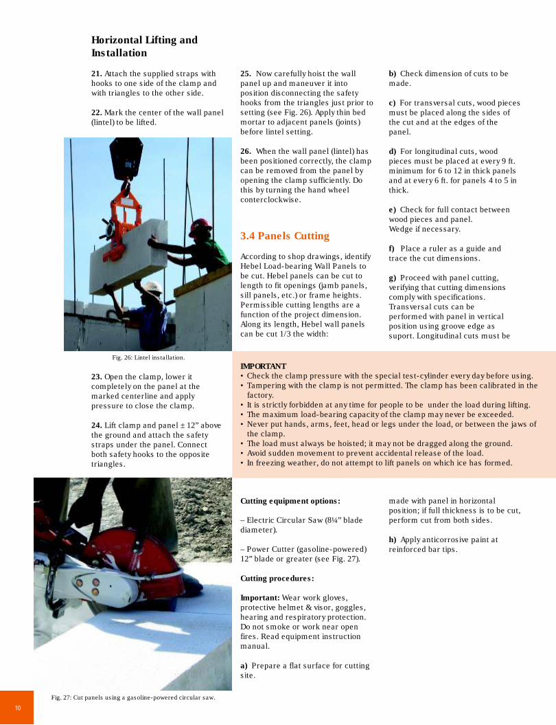
Cutting equipment options:
– Electric Circular Saw (8¼” blade diameter).
– Power Cutter (gasoline-powered) 12” blade or greater (see Fig. 27).
Cutting procedures:
Important: Wear work gloves, protective helmet & visor, goggles, hearing and respiratory protection. Do not smoke or work near open fires. Read equipment instruction manual.
a) Prepare a flat surface for cutting site.
b) Check dimension of cuts to be made.
c) For transversal cuts, wood pieces must be placed along the sides of the cut and at the edges of the panel.
d) For longitudinal cuts, wood pieces must be placed at every 9 ft. minimum for 6 to 12 in thick panels and at every 6 ft. for panels 4 to 5 in thick.
e) Check for full contact between wood pieces and panel. Wedge if necessary.
f) Place a ruler as a guide and trace the cut dimensions.
g) Proceed with panel cutting, verifying that cutting dimensions comply with specifications. Transversal cuts can be performed with panel in vertical position using groove edge as suport. Longitudinal cuts must be
made with panel in horizontal position; if full thickness is to be cut, perform cut from both sides.
h) Apply anticorrosive paint at reinforced bar tips.
23. Open the clamp, lower it completely on the panel at the marked centerline and apply pressure to close the clamp.
24. Lift clamp and panel ± 12” above the ground and attach the safety straps under the panel. Connect both safety hooks to the opposite triangles.
25. Now carefully hoist the wall panel up and maneuver it into position disconnecting the safety hooks from the triangles just prior to setting (see Fig. 26). Apply thin bed mortar to adjacent panels (joints) before lintel setting.
26. When the wall panel (lintel) has been positioned correctly, the clamp can be removed from the panel by opening the clamp sufficiently. Do this by turning the hand wheel conterclockwise.
Fig. 26: Lintel installation.
Fig. 27: Cut panels using a gasoline-powered circular saw.

11
Vertical Reinforcementaccording to design
Thin Bed Adhesive intojoint between panels
(wall thickness)
Slab/Roof RIng Beam
Rebars
Top Ring Beam
Gypsum Board(screwed directly
to Wall Panel)
Openings(windows, doors)
Base-CoatOptions:Acrylic StuccoAcrylic Base-CoatStucco Cement-based
Glass Fiber Mesh(embedded intobase-coat)
Finish Coat(Acrylic Paste)
EXTERIORFINISH
Thin Bed AdhesiveBase-Coat and MeshAAC Mouldings
ExteriorInterior3/8” gap betweengypsum board and slab
Finish Coat(Acrylic Paste, Paint,
Wall Paper, etc.)INTERIOR
FINISH
4.1 Products
Most finish systems for exterior AAC (Autoclaved Aerated Concrete) load bearing walls panels consist of three main components: base coat, reinforcing mesh, and a finish coat.
Surface preparation: Rasp joints and other areas where the AAC surface is out of plane to a smooth in-plane surface. Surface must be clean, free of dirt, oil and any other foreing matter. Loose or damaged material must be removed. Apply a tinted primer (acrylic based) in case of acrylic base-coats.
Base-Coat: Apply a layer (¼” thickness minimum) of stucco (cement-based or acrylic) or acrylic base-coats (Hebel, Sto AAC products or similar), according to manufacturer instructions. Reinforce base-coat using Fiber-glass mesh embedded in 100% of the surface area (see Fig. 28).
Finish Coat: Apply ready-mix acrylic based products as decorative and protective finish coat -top-coat- (Sto AAC products or similar). Apply finish directly over the primed wall
4 Renders andFinishes
Fig. 29: Five-story hotel built with AAC load bearing Wall Panels.
Fig. 28: Exterior and interior finish options on load bearing wall panels.
surface. Apply finish by spraying or troweling with a stainless steel trowel, depending on the finish specified (see Fig. 28 and 29).

Printed and Made in Mexico, November 2009. Xella and Hebel are registered trademarks of Xella Group.
Xella Mexicana, S.A. de C.V.
Río Amacuzac 1201 Ote.Col. Valle OrienteGarza García, NL MéxicoC.P. 66269
T: +52 (81) 8399 2424, 64 y 62F: +52 (81) 8399 2420 y 30
01 800 00 XELLA (93552)
E-mail: [email protected]
Manufacturing Facility:Carretera a Dulces Nombres Km 9.1Pesquería, NL MéxicoC.P. 66650
T: +52 (81) 8369 1515F: +52 (81) 8369 1520
Xella AAC Texas, Inc.
San Antonio Office:900 Schneider Dr.Cibolo, TX USA 78108
T: (210) 402 3223F: (210) 402 6390
1 888 SA XELLA (72 93552)
E-mail: [email protected]
Río Grande Valley Office:700 East Expressway 83San Juan, TX USA 78589
T: (956) 782 9065F: (956) 782 9068
Email: [email protected]
www.hebel.mxwww.xellamexicana.comwww.xellatexas.com