Embed Size (px)
Citation preview

XC INSTRUMENTATION SYSTEM OWNER’S MANUAL 1
XC Instrumentation System Owner’s Manual
Revision 3.0 07/05/06
XC INSTRUMENTATION SYSTEM OWNER’S MANUAL 2
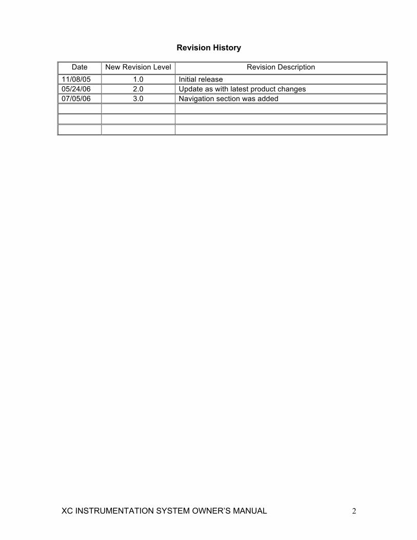
Revision History
Date New Revision Level Revision Description
11/08/05 1.0 Initial release 05/24/06 2.0 Update as with latest product changes 07/05/06 3.0 Navigation section was added
XC INSTRUMENTATION SYSTEM OWNER’S MANUAL 3
INSTRUMENTATION OPERATORS GUIDE INTRODUCTION
This operator's guide provides the information needed to operate and understand the Stoneridge LBCU installed on Freightliner X-Line Chassis. Although Freightliner chassis is equipped with many different types and styles of gauges, the system configuration for all X-Line chassis is the same and the data presented in this guide is applicable to all X-Line chassis equipped with the Stoneridge Instrumentation System. The instrument cluster is a full featured individual gauge cluster with a LBCU. The individual gauges will be sealed stepper motor movements with Light Emitting Diode (LED) backlighting. To decrease the size of the light bar height, some of the gauges may contain LED telltales. The LBCU will receive inputs from SAE J1587 and J1939, sensor and discrete inputs for driving the various gauges and telltales. The LBCU will also use LED backlighting and LED telltales for low heat and high reliability. The vehicle odometer will be displayed in the light bar. A collection of LBCU controlled, stand alone mechanical and stand alone electrical gauges will complete the total LBCU instrument package. IMPORTANT: The LBCU is capable of determining when input information is lost. The loss of input data will be noticeable to the operator by movement of the gauge to zero. The odometer value will not be driven to zero if total loss of vehicle distance data occurs. When data input is lost, hyphens (-) will replace the digits in the data field on the display screen.

XC INSTRUMENTATION SYSTEM OWNER’S MANUAL 4
WARNING AND INDICATOR LIGHTS The LBCU contains the following warning and indicator lights:
• Green Right and Left Turn Signal Indicators, which flash on and off when the outside turn signals are flashing. • Yellow CHECK TRANS Warning Light that will come on during vehicle operation if the Transmission ECU (electronic control unit) has broadcast a diagnostic fault code. Diagnostic codes indicate malfunctions in transmission operation. If this light stays on continuously during operation, have the transmission serviced as soon as possible. • Yellow ABS Warning Light. The ABS Warning Light illuminates when the vehicle is started as a self-test. If an ABS fault has been cleared, the vehicle speed must exceed 7 mph (10 km/h), for the light to go off if the ABS system is functioning normally.
WARNING If the ABS warning light does not work as described above or comes on while driving, repair the ABS system immediately to ensure full antilock braking capability. Operating the vehicle when the ABS needs to be serviced could cause an accident, possibly resulting in property damage, personal injury or death. • Blue High-Beam Indicator that illuminates when the headlights are on high beam. • Red LOW AIR Warning Light that comes on when the air pressure in the air tanks falls below 65 PSI. The warning light will normally come on when you first start the engine, but will go off when the air pressure in the air tanks reaches approximately 65 to 76 PSI. • Red PARK BRAKE Indicator light, that illuminates when the parking brakes are engaged and the ignition switch is in the ON position. • Yellow WAIT TO START Indicator. Warning Light. • Green ENGINE BRAKE Indicator that illuminates when the Engine Brake is applied.
XC INSTRUMENTATION SYSTEM OWNER’S MANUAL 5
• Green CRUISE ON Indicator, which illuminates when the Cruise Control is on. • Yellow SHIFT INHIBIT Warning light that illuminates when the Transmission ECU (electronic control unit) is prohibiting shifting. The LBCU may also include the following lights: CHECK ENGINE, STOP ENGINE, and engine protection (ENG PROT). See the Caterpillar or the Cummins Operation and Maintenance Manual for more information. IMPORTANT: When the ignition is turned on all of the Indicator Lights will illuminate for approximately 3 seconds to allow the operator to perform a bulb check.
XC INSTRUMENTATION SYSTEM OWNER’S MANUAL 6
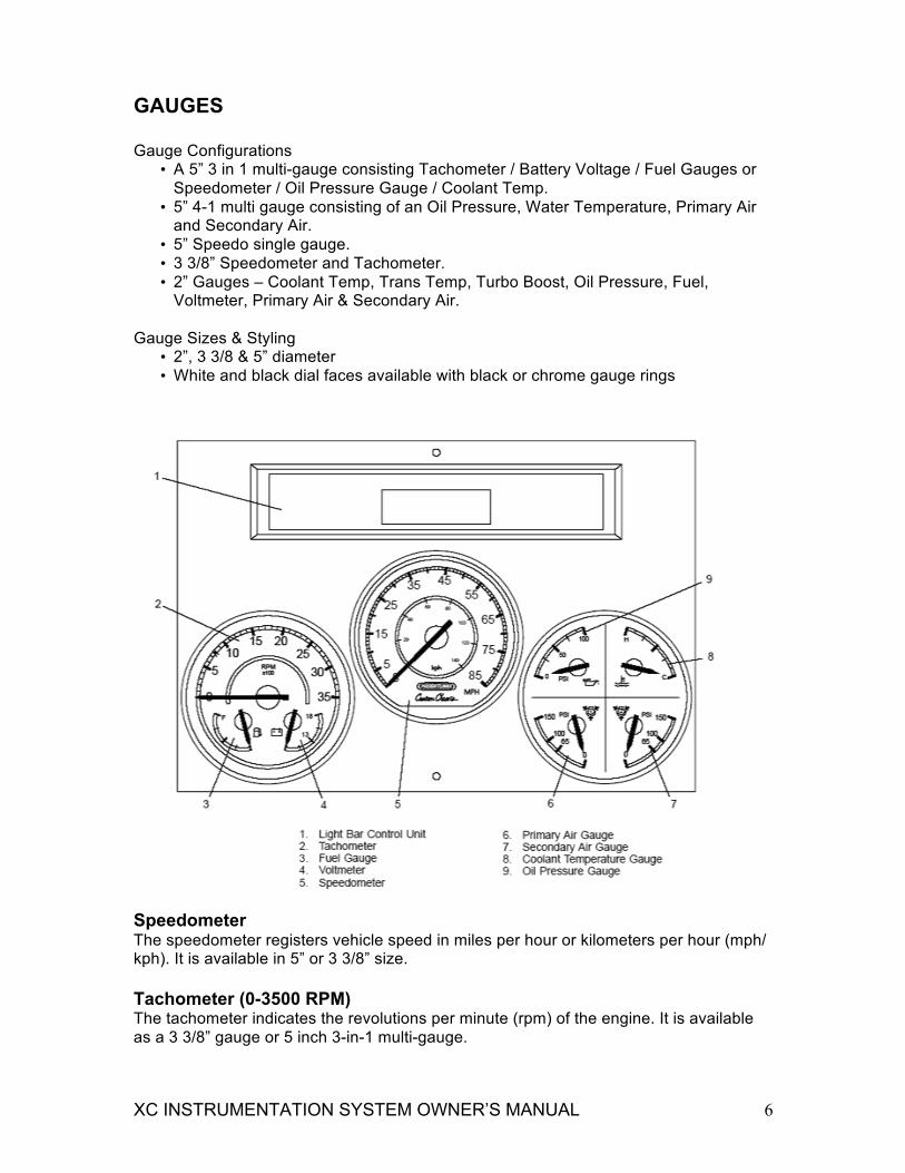
GAUGES Gauge Configurations
• A 5” 3 in 1 multi-gauge consisting Tachometer / Battery Voltage / Fuel Gauges or Speedometer / Oil Pressure Gauge / Coolant Temp.
• 5” 4-1 multi gauge consisting of an Oil Pressure, Water Temperature, Primary Air and Secondary Air.
• 5” Speedo single gauge. • 3 3/8” Speedometer and Tachometer. • 2” Gauges – Coolant Temp, Trans Temp, Turbo Boost, Oil Pressure, Fuel,
Voltmeter, Primary Air & Secondary Air. Gauge Sizes & Styling
• 2”, 3 3/8 & 5” diameter • White and black dial faces available with black or chrome gauge rings
Speedometer The speedometer registers vehicle speed in miles per hour or kilometers per hour (mph/ kph). It is available in 5” or 3 3/8” size. Tachometer (0-3500 RPM) The tachometer indicates the revolutions per minute (rpm) of the engine. It is available as a 3 3/8” gauge or 5 inch 3-in-1 multi-gauge.

XC INSTRUMENTATION SYSTEM OWNER’S MANUAL 7
Engine Coolant Temperature Gauge During normal engine operation, the coolant temperature gauge should read in the normal range. If the temperature remains below or exceeds the normal range, inspect the cooling system to determine the cause. See the Engine Operation and Maintenance Manual for normal range of operation. It is available as a standalone gauge with 2” diameter, and integrated in the multi-gauge. Fuel Level Gauge The fuel gauge indicates the amount of fuel in the fuel tank. It is available in 2” stand alone gauge or integrated in the multi-gauge. Turbo Boost Air Pressure Gauge The turbo boost gauge indicates the boost pressure at the turbo. See the engine Operation and Maintenance Manual for normal range of operation. It is available as a stand alone 2” gauge. Engine Oil Pressure Gauge The oil pressure gauge should read in the normal range. It is available as a 2” standalone gauge, and integrated in the multi-gauge. See the engine Operation and Maintenance Manual for normal range of operation.
WARNING A sudden decrease or absence of engine oil pressure may indicate mechanical failure. Bring the vehicle to a safe stop and turn off the engine. Do not operate the engine until the cause has been determined and corrected. Voltmeter The voltmeter indicates the vehicle charging system voltage when the engine is running and the engine starting battery voltage when the engine is stopped. By monitoring the voltmeter, the driver can detect potential charging system problems and have them repaired before the batteries discharge enough to create starting difficulties. The voltmeter will indicate lower voltage as the vehicle is being started or when electrical devices in the vehicle are being used. If the voltmeter shows an undercharged or overcharged condition for an extended period, have the charging system and batteries checked at a repair facility. NOTE: Some vehicles may be equipped with a battery isolator system and a gel cell battery by the body builder. On these vehicles, the voltmeter measures the average voltage of all of the batteries when the engine is running. When the engine is stopped, the voltmeter indicates only the engine starting batteries.
XC INSTRUMENTATION SYSTEM OWNER’S MANUAL 8
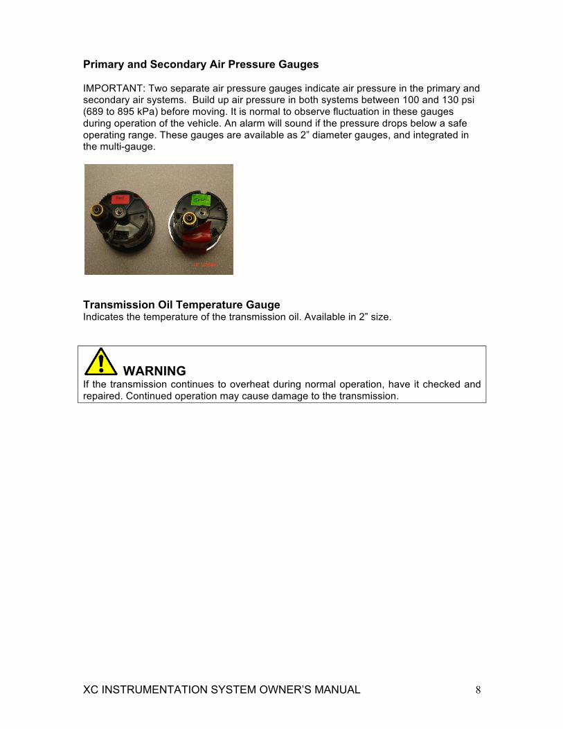
Primary and Secondary Air Pressure Gauges IMPORTANT: Two separate air pressure gauges indicate air pressure in the primary and secondary air systems. Build up air pressure in both systems between 100 and 130 psi (689 to 895 kPa) before moving. It is normal to observe fluctuation in these gauges during operation of the vehicle. An alarm will sound if the pressure drops below a safe operating range. These gauges are available as 2” diameter gauges, and integrated in the multi-gauge.
Transmission Oil Temperature Gauge Indicates the temperature of the transmission oil. Available in 2” size.
WARNING If the transmission continues to overheat during normal operation, have it checked and repaired. Continued operation may cause damage to the transmission.
XC INSTRUMENTATION SYSTEM OWNER’S MANUAL 9
4-11 AUDIBLE ALARMS During start-up, the LBCU will perform a self-test and an audible alarm will sound until the self-test is completed. If any faults are found during the self-test, ERROR will appear on the display screen. Acknowledge any alarms before proceeding to the pretrip checklist. The alarm will also sound if any of the following conditions occur. • Air pressure falls below 65 psi (448 kPa). • An audible alarm sounds anytime the low air warning light is activated. On the air
system, the low air light/audible alarm will normally come on when the engine is first started, but will go off when the air pressure in the air tanks reaches approximately 65 to 76 psi (448 to 524 kPa). The parking brake will not disengage until the air pressure has reached 65 psi (448 kPa).
• Emergency engine shutdown is activated. • The parking brake is applied and the transmission is not in neutral. • The transmission is in neutral or the ignition is off, and the parking brake is not set
and the service brake is not depressed. • The turn indicator is active. • The audible alarm will sound continuously anytime the ignition is turned off when the
panel lamps are still illuminated.
4-12 EMERGENCY SHUTDOWN The LBCU will shut down if the voltage supply is not within the normal operating range of 9 to 16 volts for more than 10 milliseconds (msec). During emergency shutdown, the gauge pointers will freeze, the display will go blank, and the lamps will turn off. When the power is restored to within the normal operating range following an emergency shutdown, the needles will resynchronize to zero, and the self-test will be performed before resuming normal operation.
XC INSTRUMENTATION SYSTEM OWNER’S MANUAL 10
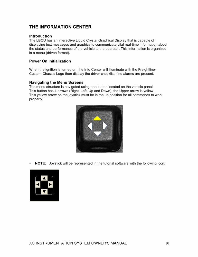
THE INFORMATION CENTER Introduction The LBCU has an interactive Liquid Crystal Graphical Display that is capable of displaying text messages and graphics to communicate vital real-time information about the status and performance of the vehicle to the operator. This information is organized in a menu (driven format). Power On Initialization When the ignition is turned on, the Info Center will illuminate with the Freightliner Custom Chassis Logo then display the driver checklist if no alarms are present. Navigating the Menu Screens The menu structure is navigated using one button located on the vehicle panel. This button has 4 arrows (Right, Left, Up and Down), the Upper arrow is yellow. This yellow arrow on the joystick must be in the up position for all commands to work properly.
• NOTE: Joystick will be represented in the tutorial software with the following icon:
XC INSTRUMENTATION SYSTEM OWNER’S MANUAL 11
Menu Structure The menu structure is organized around Top level menus, the Ignition Off Screens, Home Screen Overview Screen, and the Setup Main and Diagnostics menus. The following options are found in the menu and sub-menus of the home screen.
• A pretrip inspection checklist that includes 19 items and 10 driver-entered options. Once each item has been reviewed, use the toggle switch and click the right arrow to place a check by the item. Click the left arrow to exit the checklist
• Driver’s Favorite Categories – There are nine categories that the driver can select from: three can be viewed at one time. Select the category desired by using the up/down toggle switch. Then use the toggle switch and click the right arrow for three seconds to access the submenus within each category. Finally use the toggle switch and click the left arrow to exit.
• Setup / Maintenance / Diagnostics screen is actually three different categories for the driver to use. They are as follows: 1. Setup- Includes set time and date, configure checklist, select metric / english,
set LCD properties 2. Maintenance – Includes engine oil, engine air filter, engine fuel filter,
transmission oil, generator oil, generator fuel filter, generator use time. There is a service reminder which tells you when to provide service to the engine (configurable, can be set from 1,000mi to 100,000mi).
3. Diagnostics – Includes check gauges, check icons, check inputs, check outputs, engine diagnostics, ABS diagnostics, and hardware / software version.
The following steps are used to make changes within the various categories.
1. From the Driver’s Favorite Category menu use the toggle switch and hold the right arrow down for five seconds to select the setup / maintenance / diagnostics screen
2. Press the down arrow on the toggle switch to select setup, maintenance or diagnostics.
3. Press the right arrow on the toggle switch to select the subcategory; “Set Time and Date” for example.
4. Use the left / right arrows on the toggle switch to change the information, ad the up / down arrows to move within the subcategory.
5. Once all changes have been made, hold the right arrow on the toggle switch Ignition Off Screens
• Headlights ON displays odometer. • Generator ON displays generator hours. • Park brake not set. Icon will be on when park brake is set.
Home Screen Overview • Alarms: Alarm messages have priority over other display screens. If no alarms are
present or all alarms have been acknowledged the driver checklist will be displayed. • Driver checklist which includes:

XC INSTRUMENTATION SYSTEM OWNER’S MANUAL 12
Favorite Display: 9 lines, 3 viewed at a time. The driver can select which item to view
with left arrow. Time, Odometer, Trip, Today, Leg, Road speed, Trans, Generator Hours.
Setup Main and Diagnostic • Select Diagnose Category: Includes Check gauges, Check icons, Check inputs,
Check outputs, Engine diagnostics, ABS diagnostics, SW HW version, Odometer diagnostics, and Input override.
• Select Maintenance Category: Includes Engine Maintenance, Transmission Maintenance, and Generator Maintenance.
• Select Setup Category: Includes Set time and date, Configure check list, Select English/metric and Set LCM properties.
Setting Time and Date 1 From favorite menu, hold right button 3 sec to Select SMD Category 2 Press right to Select Setup Category 3 Right to Highlight Set Time and Date 4 Left and right to select, up and down to change 5 Right to save and exit 6 Left to exit without saving Changing from English/Metric
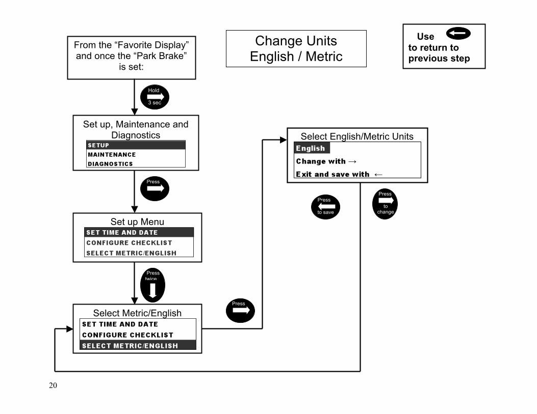
1 From favorite menu, hold right button 3 sec to Select SMD Category 2 Press right to Select Setup Category 3 Right to highlight Select English/Metric 4 Right to change 5 Left to save and exit
Menu Structure Roadmap The menu structure road map is provided below that illustrates the screens that are available in the Info Center, the path to specific screens, and the details of each individual screen. Comments are included where necessary for added clarification.
13
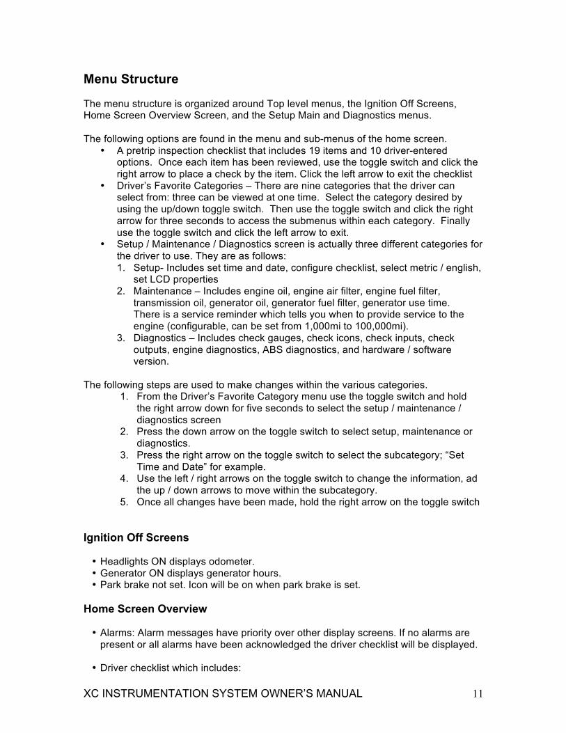
CHECKLIST MENU Here you have to verify every item on the checklist and check it with the Right Key. You can move up/down on the checklist with the Up/Down Key, or you can skip it by holding the Right Key 3 seconds. Once you have acknowledged all the items, the Control will take you to the next display.
FAVORITE DISPLAY Here you can configure it to see what you want by selecting a line with the Up/Down Key, reset a value, change the Line Format/Information, or change the information on the selected line. To simulate the Alarm messages on the display, set it to the number of desired alarms using the control under the text 'Number of Alarms'. To access the Setup Maintenance and Diagnose Menus hold the Right Key for 3 seconds. Park Brake must be set and no line selected in the menu. You can turn On/Off the Ignition and the Headlights switches whenever you want to see what happens.

14
Favorite Display
Set up maintenance and diagnose
Checklist Menu
Check an option
Use to return to previous step
Change format/Information
Favorite Display
Press
Hold
3 sec Press Press
Press Skip checklist menu
Press Press Reset value
Reset value option is only applicable to today dist, leg dist,
trip dist
No
Press
Format Options • Gen hrs • Date & time (mo/day/yr hr:min:sec;
month. Day hr:min:sec; hr:min:sec) • Odometer • Today: dist; time; fuel, fuel econ,
AVSPD, idle time • Leg: dist; time; fuel, fuel econ, AVSPD,
idle time • Trip: dist; time; fuel, fuel econ, AVSPD,
idle time • Road SPD; eng RPM; oil press; inst
fuel econ; fuel used; eng hrs; eng temp; trbo press; volt)
• Trans temp; gear.
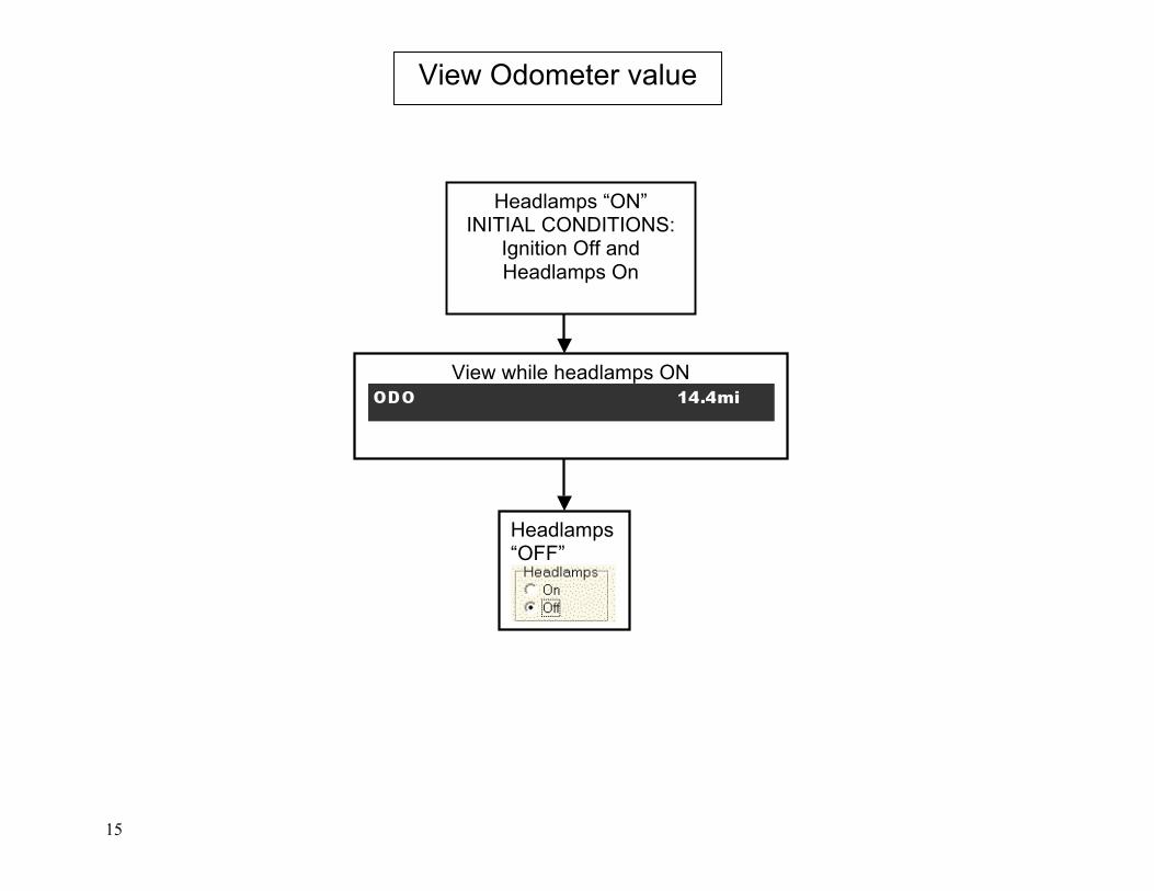
15
View Odometer value
Headlamps “ON” INITIAL CONDITIONS:
Ignition Off and Headlamps On
Headlamps “OFF”
View while headlamps ON
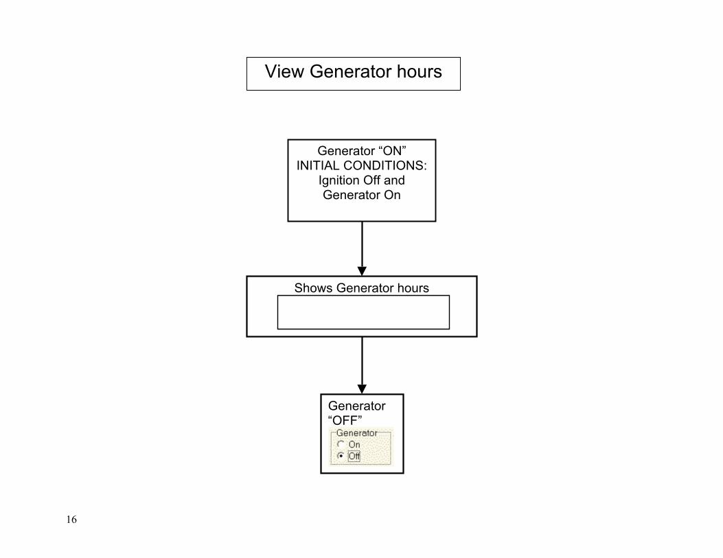
16
Generator “ON” INITIAL CONDITIONS:
Ignition Off and Generator On
Generator “OFF”
Shows Generator hours
View Generator hours

17
From the “Favorite Display” and once the “Park Brake” is set:
Set up, Maintenance and Diagnostics
Set up Menu
Set Up Menu
Use to return to previous step
Hold
3 sec
Press
Press
to exit
SETUP MAINTENANCE AND DIAGNOSTICS
This menu allows you to access technical and
diagnostics information in the product. On this
menu you will be able to read inputs, read sensor
data, change information and test output signals.
Select an option moving with the Up/Down Key
and then press the Right Key. If you want to Exit
this menu press the Left Key.

18
Press to change
Hr (0 – 23)
Set Time and Date
Month (1 –12)
Day (1 –31)
Year (00-99)
Min (0 – 59)
Format (AM/PM/24)
Set up, Maintenance and Diagnostics
Set up Menu
From the “Favorite Display” and once the “Park Brake” is set:
Set time and date
Use to return to previous step
Press
Press
Press
Press
Press
Press
Press
Press to change
Press to change
Press to change
Press to change
Press to change
Press to change
Press
To save
Press
to cancel
Hold
3 sec
To save, the cursor must be all the way to the right
Must be left To exit, the cursor must be all
the way to the left
19
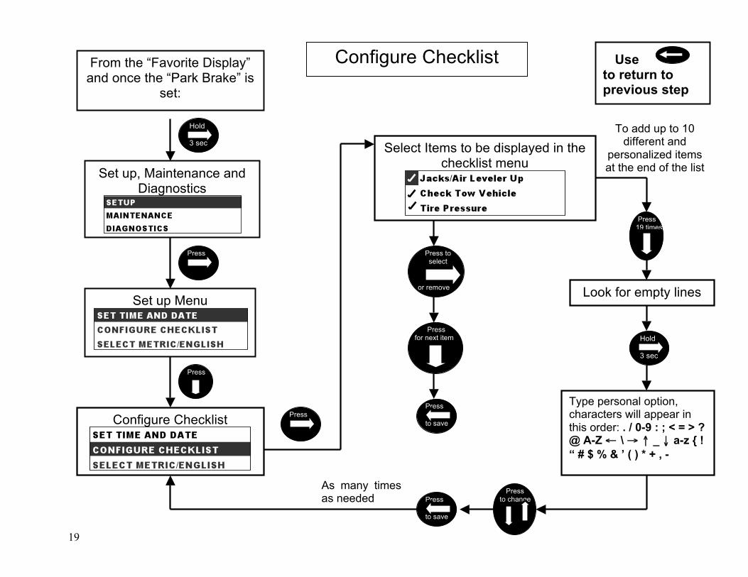
Use to return to previous step
Set up, Maintenance and Diagnostics
Set up Menu
From the “Favorite Display” and once the “Park Brake” is
set:
Press
Press
Configure Checklist
Press
Select Items to be displayed in the checklist menu
Press to select
or remove
Press for next item
Press
to save
Hold
3 sec
Configure Checklist
To add up to 10 different and
personalized items at the end of the list
Press 19 times
Hold
3 sec
Look for empty lines
Press to change Press
to save
As many times as needed
Type personal option, characters will appear in this order: . / 0-9 : ; < = > ? @ A-Z ← \ → ↑ _ ↓ a-z { ! “ # $ % & ’ ( ) * + , -
20
Set up, Maintenance and Diagnostics
Change Units English / Metric
T Set up Menu
Select Metric/English
From the “Favorite Display” and once the “Park Brake”
is set:
Use to return to previous step
Press
Press
Press twice
Select English/Metric Units
Press
to save
Press
to change
Hold
3 sec

21
Factory Settings
Dimm w hdlghts off
Dimm w hdlghts on
Set Display Properties Menu Use to return to previous step
Press
Press
Set up, Maintenance and Diagnostics
Set up Menu
Set Display Properties line
From the “Favorite Display” and once the “Park Brake” is
set:
Press
Hold
3 sec
Press 3 times
Press
to change
Press
to change
Increments of 5% from 0% to 95%
Press
to save & exit
Press
Factory settings cannot be changed; they will always be 25% for Hdlghts Off and On
DISPLAY PROPERTIES Here you can set the dimming level for the Headlights or select the default values for it. To select the default values choose Yes on the Factory Settings line, otherwise select the dimming level you want. Press the Right Key to change the values and the Up/Down Key to move. Press the Left Key to save and Exit.
22
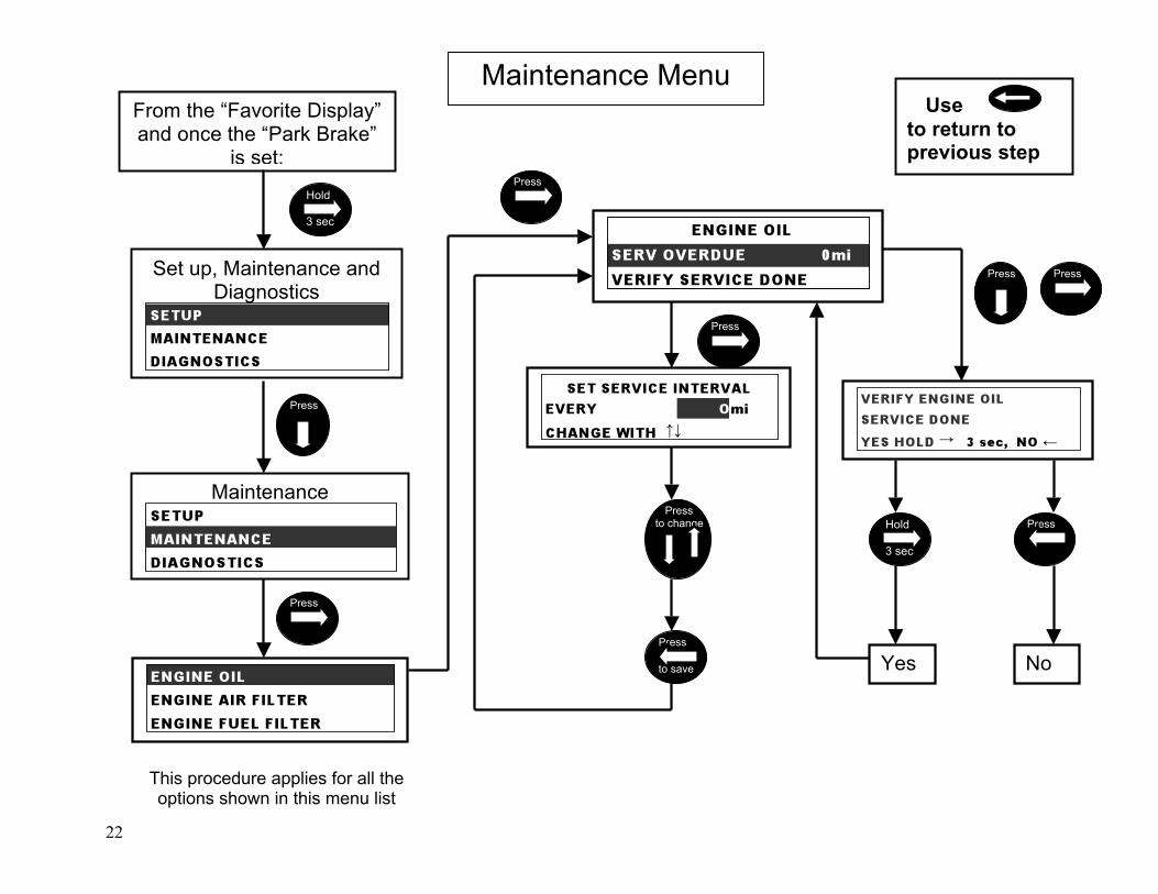
Maintenance Menu Use
to return to previous step
Maintenance
From the “Favorite Display” and once the “Park Brake”
is set:
Set up, Maintenance and Diagnostics
Hold
3 sec
Press
Press
Press
This procedure applies for all the options shown in this menu list
Press
Press to change
Press
to save
Press Press
Hold
3 sec
Yes No
Press

23
Check Check Engine ABS SW debug Odometer
Diagnostics Menu Use
to return to previous step
Diagnostics menu
From the “Favorite Display” and once the
“Park Brake” is set:
Set up, Maintenance and Diagnostics
Press
Hold
3 sec
Press twice
24
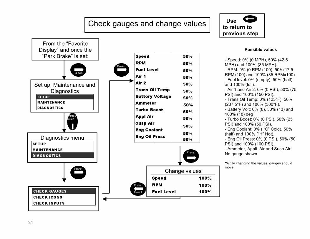
Check gauges and change values Use to return to previous step
Diagnostics menu
From the “Favorite Display” and once the
“Park Brake” is set:
Set up, Maintenance and Diagnostics
Change values
Hold 3 sec
Press
Press
Press
Press twice
Press
to exit
Possible values - Speed: 0% (0 MPH), 50% (42.5 MPH) and 100% (85 MPH). - RPM: 0% (0 RPMx100), 50%(17.5 RPMx100) and 100% (35 RPMx100) - Fuel level: 0% (empty), 50% (half) and 100% (full). - Air 1 and Air 2: 0% (0 PSI), 50% (75 PSI) and 100% (150 PSI). - Trans Oil Temp: 0% (125°F), 50% (237.5°F) and 100% (300°F). - Battery Volt: 0% (8), 50% (13) and 100% (18) deg - Turbo Boost: 0% (0 PSI), 50% (25 PSI) and 100% (50 PSI). - Eng Coolant: 0% ( “C” Cold), 50% (half) and 100% (“H” Hot). - Eng Oil Press: 0% (0 PSI), 50% (50 PSI) and 100% (100 PSI). - Ammeter, Appli. Air and Susp Air: No gauge shown *While changing the values, gauges should move

25
Check icons and change values Use to return to previous step
Diagnostics menu
From the “Favorite Display” and once the “Park Brake”
is set:
Set up, Maintenance and Diagnostics
Turn On and Off
Hold
3 sec
Press
Press Press
Press
Press
Press twice
Press
to exit
Use “Welcome Screen” to locate icons as they
are being lighted
To select next option
Press

26
From the “Favorite Display” and once the
“Park Brake” is set:
Set up, Maintenance and Diagnostics
Diagnostics menu
Check inputs
Check inputs
Use to return to previous step
Hold
3 sec
Press
Press
Press twice
Press twice
Press
to exit
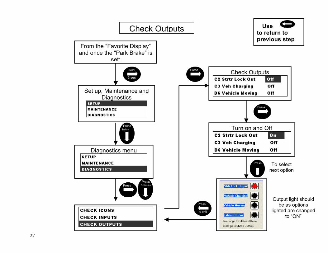
27
Check Outputs
Turn on and Off
Check Outputs Use to return to previous step
From the “Favorite Display” and once the “Park Brake” is
set:
Set up, Maintenance and Diagnostics
Diagnostics menu
Hold
3 sec
Press twice
Press Press 3 times
Press
Press
Press
to exit
To select next option
Press
Output light should be as options
lighted are changed to “ON”
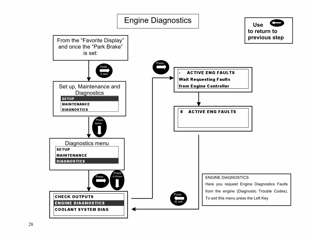
28
From the “Favorite Display” and once the “Park Brake”
is set:
Set up, Maintenance and Diagnostics
Diagnostics menu
Hold
3 sec
Press twice
Press Press 4 times
Press
Press
to exit
Use to return to previous step
Engine Diagnostics
ENGINE DIAGNOSTICS
Here you request Engine Diagnostics Faults
from the engine (Diagnostic Trouble Codes).
To exit this menu press the Left Key
29
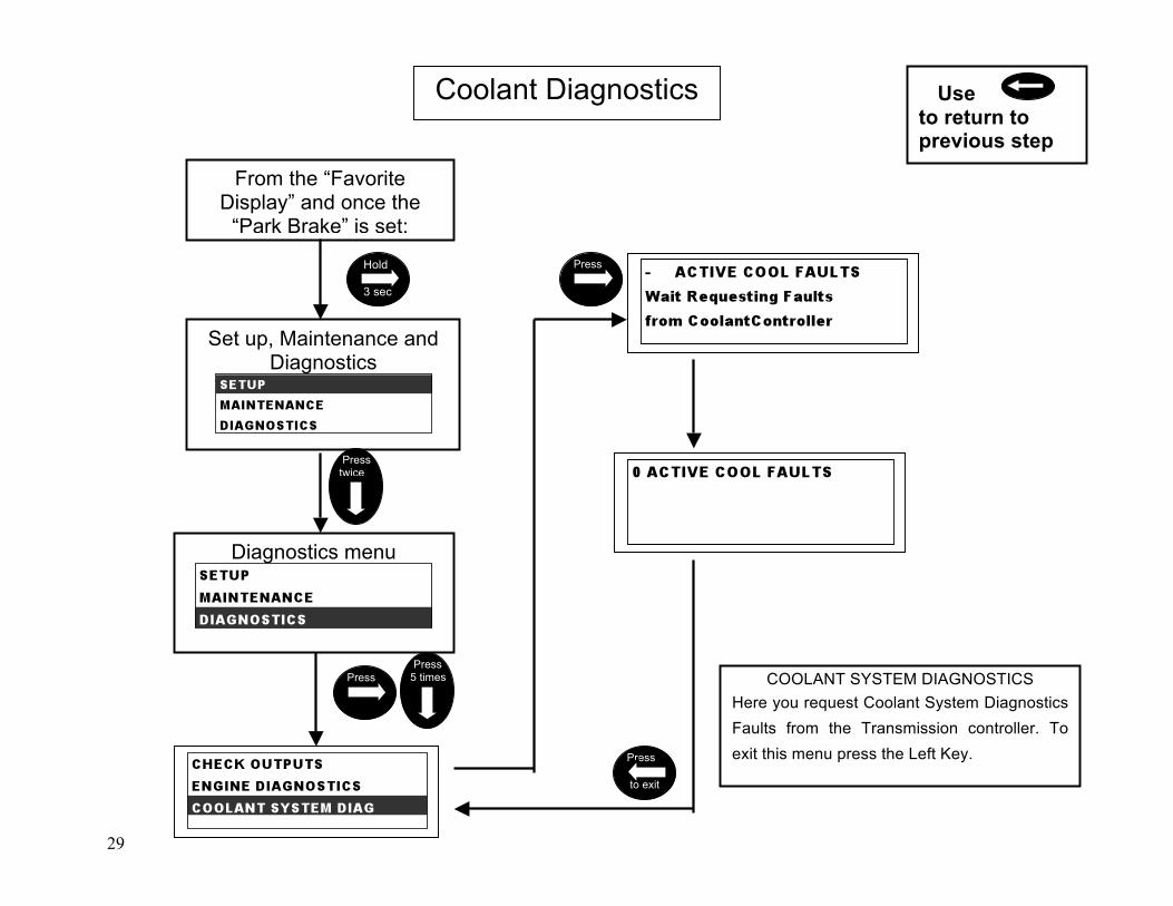
From the “Favorite Display” and once the
“Park Brake” is set:
Set up, Maintenance and Diagnostics
Diagnostics menu
Hold
3 sec
Press twice
Press Press 5 times
Press
Press
to exit
Coolant Diagnostics Use to return to previous step
COOLANT SYSTEM DIAGNOSTICS Here you request Coolant System Diagnostics Faults from the Transmission controller. To exit this menu press the Left Key.
30
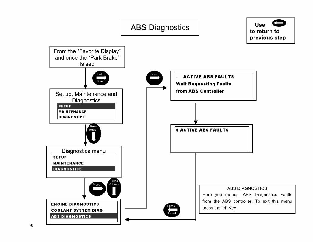
ABS Diagnostics Use to return to previous step
From the “Favorite Display” and once the “Park Brake”
is set:
Set up, Maintenance and Diagnostics
Diagnostics menu
Hold
3 sec
Press twice
Press Press 6 times
Press
Press
to exit
ABS DIAGNOSTICS Here you request ABS Diagnostics Faults from the ABS controller. To exit this menu press the left Key
31
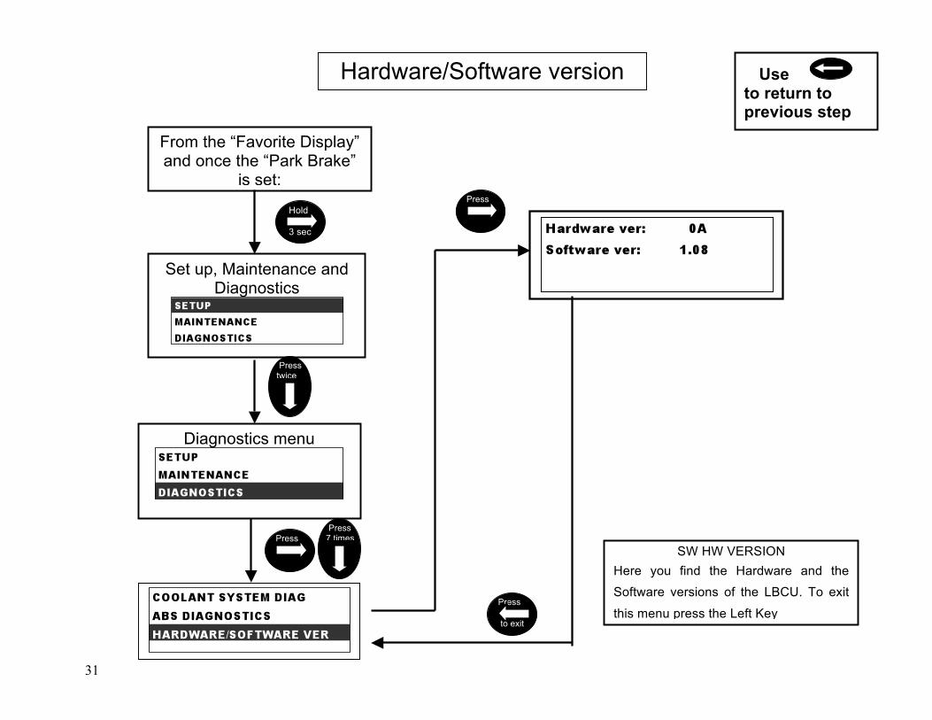
Hardware/Software version Use to return to previous step
From the “Favorite Display” and once the “Park Brake”
is set:
Set up, Maintenance and Diagnostics
Diagnostics menu
Hold
3 sec
Press twice
Press Press 7 times
Press
Press
to exit
SW HW VERSION Here you find the Hardware and the
Software versions of the LBCU. To exit
this menu press the Left Key

32
Check Internal Data Use to return to previous step
From the “Favorite Display” and once the
“Park Brake” is set:
Set up, Maintenance and Diagnostics
Diagnostics menu
Check Internal Data
Hold
3 sec
Press twice
Press Press 9 times
Press
Press
to exit
CHECK INTERNAL DATA
Here you can find the values of
the Internal Data Move Up/Down
with the Up/Down Key. To exit
this menu press the Left Key

33
From the “Favorite Display” and once the “Park Brake”
is set:
Odometer diagnostics Use to return to previous step
Set up, Maintenance and Diagnostics
Diagnostics menu
Hold
3 sec
Press twice
Press Press 9 times
Press
Press
to exit

34
Check Input Override Use to return to previous step
From the “Favorite Display” and once the “Park Brake”
is set:
Set up, Maintenance and Diagnostics
Diagnostics menu
Check Input Override
Hold
3 sec
Press twice
Press Press 10 times
Press
Press
to exit
INPUT OVERRIDE
Here you can override the Inputs values for testing periodic message transmission functions. Move Up/Down with the Up/Down Key and once selected modify the values with the Right Key. To exit this menu press the Left Key
Press to
change